experimental radio indoor positioning systems …cdn.intechweb.org/pdfs/9941.pdfexperimental radio...
TRANSCRIPT

Experimental Radio Indoor Positioning Systems Based on Round-Trip Time measurement 195
Experimental Radio Indoor Positioning Systems Based on Round-Trip Time measurement
Alessio De Angelis, Antonio Moschitta, Peter Händel and Paolo Carbone
X Experimental Radio Indoor Positioning Systems
Based on Round-Trip Time Measurement
Alessio De Angelis1, Antonio Moschitta1, Peter Händel2 and Paolo Carbone1 1Department of Electronic and Information Engineering (DIEI), University of Perugia,
Italy 2Signal Processing Lab, ACCESS Linnaeus Centre, Royal Institute of Technology,
Stockholm, Sweden
1. Introduction
This chapter presents the design issues and performance characterization results of two experimental systems for radio distance measurement and positioning. The main envisioned application area for these systems is the indoor environment, characterized by an insufficient coverage of global navigation satellite systems and by issues related to the indoor radio propagation channel. In particular, such issues include multipath propagation and the absence of line-of-sight. Furthermore, the applications for indoor positioning systems usually require a high degree of accuracy, which can be of the order of a centimetre, in the position estimation. Recently, this research area experienced a considerable growth and the state of the art is characterized by a wide array of solutions. In this context, the systems described in the present chapter are based on two different approaches: an Ultra-Wideband (UWB) pulse-based solution (De Angelis et al., 2008a), (De Angelis et al., 2009a), (De Angelis et al., 2009c) and a platform developed using commercial devices complying with the ZigBee standard (Santinelli et al., 2009). However, both approaches share the same principle of operation: the measurement of signal Time-Of-Flight. In particular, the systems are capable of measuring the Round-Trip-Time (RTT), eliminating the need for accurate synchronization between transmitters and receivers. The time interval measurement function is performed in both systems by a commercial Time-to-Digital Converter (TDC) with 50 ps rms resolution. The first approach involves the complete design process of the pulse-UWB radio interface, that is the circuitry necessary to properly generate and detect a sub-nanosecond pulse. These blocks have been designed and built from scratch using off-the-shelf components where possible. Furthermore, other relevant blocks are the timing and control logic, the interface with the TDC and the communication with a PC for data processing. The overall architecture has been developed using a master-slave approach, in which several slaves (pulse repeaters) are placed in fixed and known positions and thus constitute the infrastructure of the system. The master device is capable of measuring its distance with respect to the slaves and of estimating its position by means of triangulation algorithms. A
8
www.intechopen.com

Advances in Measurement Systems196
basic on-off pulse-keying protocol has been implemented in order to enable the communication of the master with multiple slaves. The second approach uses commercial ZigBee radio interface devices and is based on the RTT measurement of communication packets. The main feature is the introduction of a self-calibration method, aiming at removing the bias introduced by the latencies of the fixed-position nodes. Detailed descriptions of the architectures as well as experimental test results are presented in this chapter, together with a comparison and discussion of the advantages and disadvantages of each approach.
2. State of the art in the field of indoor positioning
Indoor positioning is the object of a considerable research interest. Accurate geolocation, in fact, represents an enabling technology for indoor location-aware sensor networks (Gezici et al., 2005) (Wymeersch et al., 2009). Some of the real-life applications for research in this field are related to the industry and logistic areas, e.g. for efficient asset tracking (Fontana, 2004). Another application area of interest is the location and tracking of emergency personnel and incident first responders (Rantakokko et al., 2007). In this context, both ad-hoc systems and architectures based on pre-existing communication infrastructures have been developed in the literature. Comprehensive surveys of the fundamental positioning strategies, as well as the main research and commercial systems in the indoor positioning area can be found in (Pahlavan et al., 2002) (Liu et al., 2007). In the following subsections, some aspects of the state of the art are presented, related to the research activity described in the rest of this chapter.
2.1 UWB indoor positioning In the specific field of UWB systems for indoor positioning, there is also a large number of research activities. In fact, such systems are considered good candidates for accurate ranging, mainly due to their fine time resolution, which is a consequence of the very large bandwidth (Di Benedetto et al., 2006). Other advantages include robustness to multipath propagation, low-power operation, immunity to communication interception and possible penetration through various types of materials (Fontana, 2004), (Molisch, 2005), (Gezici et al., 2005). In the following subsections, the UWB indoor positioning field is presented by first describing the regulatory context of the technology, then by describing some of the main approaches and systems in the literature.
www.intechopen.com
Experimental Radio Indoor Positioning Systems Based on Round-Trip Time measurement 197
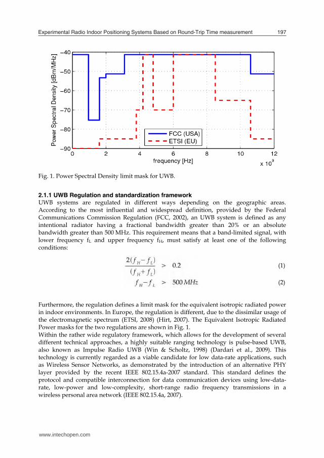
Fig. 1. Power Spectral Density limit mask for UWB.
2.1.1 UWB Regulation and standardization framework UWB systems are regulated in different ways depending on the geographic areas. According to the most influential and widespread definition, provided by the Federal Communications Commission Regulation (FCC, 2002), an UWB system is defined as any intentional radiator having a fractional bandwidth greater than 20% or an absolute bandwidth greater than 500 MHz. This requirement means that a band-limited signal, with lower frequency fL and upper frequency fH, must satisfy at least one of the following conditions:
Furthermore, the regulation defines a limit mask for the equivalent isotropic radiated power in indoor environments. In Europe, the regulation is different, due to the dissimilar usage of the electromagnetic spectrum (ETSI, 2008) (Hirt, 2007). The Equivalent Isotropic Radiated Power masks for the two regulations are shown in Fig. 1. Within the rather wide regulatory framework, which allows for the development of several different technical approaches, a highly suitable ranging technology is pulse-based UWB, also known as Impulse Radio UWB (Win & Scholtz, 1998) (Dardari et al., 2009). This technology is currently regarded as a viable candidate for low data-rate applications, such as Wireless Sensor Networks, as demonstrated by the introduction of an alternative PHY layer provided by the recent IEEE 802.15.4a-2007 standard. This standard defines the protocol and compatible interconnection for data communication devices using low-data-rate, low-power and low-complexity, short-range radio frequency transmissions in a wireless personal area network (IEEE 802.15.4a, 2007).
(2)
(1)
www.intechopen.com
Advances in Measurement Systems198
However, it is important to mention that another variant of UWB signals, namely Multi-Band Orthogonal Frequency Division Multiplexing, is also currently under development and it is mostly intended for high data-rate short-range wireless communications (Wireless USB, 2007), (WiMedia Alliance, 2009), (Kumar & Buehrer, 2008).
2.1.2 Overview of approaches for UWB indoor geolocation In the scientific literature, the state of the art in UWB indoor geolocation includes works based on different approaches, methodologies and objectives. In particular, it is possible to find works based on experimental testbeds realized using general-purpose instrumentation (Low et al., 2005). Furthermore, a considerable number of papers deal with the development of integrated circuits. Inside this category, of particular relevance are the System–on-Chip UWB pulse generator implementations (Sim et al., 2009) (Phan et al., 2007), and transceiver prototypes (Terada et al., 2006). Other works are aimed at presenting complete architecture solutions and associated challenges (Chandrakasan et al., 2009) (Mahfouz et al., 2008) (Stoica et al., 2005). Also, the results of additional research activities consist of experimental characterizations of full-featured positioning systems (Oh, 2009), (Fontana, 2004). Moreover, it is possible to mention several commercially-available UWB geolocation systems, mainly intended for industrial and logistics applications (Zebra Enterprise Solutions, 2009), (UbiSense, 2009), (TimeDomain, 2009). These systems provide positioning accuracies in the order of magnitude of 10 cm, with communication ranges of several tens of metres. Such commercial solutions typically include an infrastructure which is flexible and customizable to the user needs. Some of the additional features provided by such solutions include centralized localization algorithms, robust multiple access schemes, alternative channels for network coordination, and cell-based structures for network scalability.
2.2 ZigBee indoor positioning Apart from UWB ad-hoc positioning solutions, other approaches for geolocation are designed to exploit a pre-existing wireless communication infrastructure. Among these, the systems based on the ZigBee technology (ZigBee Alliance, 2007) represent an emerging research area. ZigBee is considered as an interesting choice for indoor geolocation thanks to several features such as low power consumption, good range, low cost and wide commercial diffusion. Furthermore, by using this technology, the positioning functions can be easily integrated with other communication services in a wireless sensor network.
www.intechopen.com

Experimental Radio Indoor Positioning Systems Based on Round-Trip Time measurement 199
Fig. 2. Principle of operation of the RTT distance-measurement approach. The most common strategy for geolocation using ZigBee signals is based on the Received Signal Strength (RSS) of communication signals (Blumenthal et al., 2007) (Cho et al., 2007). Using this approach, an estimate of the distance between a transmitter and a receiver is obtained by means of the received power level, given an appropriate model for the power loss of the transmission channel. Such a measure may be provided by some commercial ZigBee hardware as a RSS Indicator (RSSI). However, the achievable accuracy of RSS-based ZigBee positioning systems is usually in the order of magnitude of 1 m. Better results can potentially be obtained with Time-Of-Arrival methods, as demonstrated by some works found in the literature (Santinelli et al., 2009) (Corral et al., 2008) (Schwarzer et al., 2008).
2.3 Indoor Radio Propagation Channel One of the fundamental issues associated to radio geolocation is represented by the propagation channel. In fact, especially in indoor scenarios, the channel is strongly affected by multipath fading, a phenomenon which is of key relevance in both the approaches considered in this work. In particular, for the UWB case, due to the high bandwidth and fine time resolution of the pulses, the system is intrinsically able to discriminate a large number of paths (Lee & Scholtz, 2002). In this field, channel modeling research activities have been published in the literature, see (Molisch, 2005) (Molisch et al., 2005). Furthermore, the ZigBee solution requires an essentially different approach to the multipath problem, since it can be basically considered as a narrowband system. In particular, as a ZigBee receiver relies on correlation techniques to synchronize itself with an incoming packet, RTT measurements may be affected by increased correlation times when input signal power is reduced by multipath. The goal of research activity in this field is to properly model and compensate this phenomenon, in order to accurately estimate its effect on the measured signal time-of-flight (Hirschler-Marchand & Hatke, 2002).
www.intechopen.com

Advances in Measurement Systems200
Fig. 3. Architecture of the realized master device prototype (De Angelis et al., 2008a).
3. UWB pulse-based ranging and positioning system
The basic principle of operation of the developed UWB ranging system involves the accurate measurement of the RTT of a pulse propagating between two transceivers, schematized in Fig. 2. In order to implement this accurate measurement in a compact, low-power and portable platform, an approach based on a TDC has been employed. In particular, the commercial integrated TDC-GP2 by Acam Messelectronic Gmbh, has been used, having a rms resolution of 50 ps (Acam GmbH, 2008). This order of magnitude is appropriate for accurate distance measurement in a typical indoor application, since it implies a 0,75 cm theoretical resolution when a RTT approach is used. Apart from the time-interval measuring unit, a significant challenge in the development of the system has been the design from scratch of all the main building blocks, such as the radio front-end (pulse generation and pulse detection), timing, control and results processing.
www.intechopen.com

Experimental Radio Indoor Positioning Systems Based on Round-Trip Time measurement 201
RX antenna
TX antenna
Q1
GND
Pulse Generator
P1.5
60 ns
100 nsEN
P1.7
TX Delay
Three State Buffer
ResetDelay
P1.4
P1.6
MSP430F2013
EN
EN
Three State Buffer
Three State Buffer
100 ns
Pulse Detector
Timing and Reset Logic
IN OUT
RESET
Fig. 4. Architecture of the slave device (De Angelis et al., 2008a).
(a) (b) Fig. 5. Block diagram of the two receiver architectures: a) Constant-current biased tunnel-diode threshold detector. b) Energy detection receiver.
3.1 Ranging system architecture The system is based on a master-slave architecture, where the master is a transceiver with the capability of measuring the time interval between transmission and reception of a pulse. On the other hand, the slave device has a simpler architecture, lacks the time-interval measuring capability and is designed as a pulse repeater. The block diagram of the master device is shown in Fig. 3. As mentioned above, the RTT of a pulse propagating between the master and the slave is measured by the TDC, while the low-power microcontroller (Texas Instruments MSP430) is used to program it and read measurement results through a Serial Peripheral Interface (SPI). The data are also transmitted by the microcontroller to a Personal Computer for subsequent processing, in order to estimate the master-slave distance.
www.intechopen.com

Advances in Measurement Systems202
371.5 372 372.5 3730
500
1000
1500
measured time interval [ns]
histogram
Fig. 6. Experimental results, raw RTT data, obtained using the tunnel-diode threshold detector. Normalized histogram, 7500 RTT measurement results at a distance of 140 cm. Furthermore, an important block is represented by the timing and reset logic network, entirely realized with commercial off-the-shelf CMOS circuits. Its purpose is to provide proper timing for the reset path of the pulse detector. Using this network, the self-detection condition, that is the detection of a pulse transmitted by the same device, is avoided. The block diagram of the slave device is shown in Fig. 4. It can be noticed that its architecture is similar to that of the master. The main difference is that this device doesn't implement the time-interval measurement hardware. There are also differences in the timing and reset logic. A relevant section of the research activity has been dedicated to the comparison of several different UWB pulse generation strategies that exist in literature. The nature of this comparison has been mainly experimental with requirements of architectural simplicity and of the use of commercial off-the-shelf components, where possible. The results of this experimental comparison activity are presented in (De Angelis et al., 2008b). The various strategies investigated were based on logic gates, step recovery diodes and avalanche transistors. At the end of the comparison it was established that the step recovery diode pulse generator approach is the one that provides the best trade-off between transition time, amplitude and power consumption. In particular, it provides a negative pulse with an amplitude of about -8.2 V and a measured fall time of about 690 ps. Furthermore a -10 dB bandwidth of about 500 MHz has been observed, thus satisfying both the requirements in equations (1)-(2). This generator has been chosen for use in the complete UWB geolocation system experimental prototype. Another fundamental building block for the system is the pulse detector. In this regard two strategies have been analysed: a signal-threshold detector and an energy detector. For details on the design and implementation of these devices, the reader can refer to (De Angelis et al., 2008a). Fig. 5a shows the diagram of the threshold detector, which is based on a constant-current biased tunnel diode.
www.intechopen.com

Experimental Radio Indoor Positioning Systems Based on Round-Trip Time measurement 203
40 60 80 100 120 140 160 180 200 220 24050
100
150
200
250
actual distance [cm](a)
measured
distance [cm]
measured distanceactual distance
40 60 80 100 120 140 160 180 200 220 2400
5
10
15
actual distance [cm](b)
absolute
difference [cm]
Fig. 7. Experimental results obtained with the tunnel-diode threshold detector, with the application of the calibration factor. (a) Measured distance vs actual distance. (b) Absolute difference between the measured and actual distances. The bars along the absolute difference curve represent the standard deviation in centimetres. The block diagram of the energy detector, which has been implemented by means of a commercial RF circuit with an integrated comparator (Linear Technologies LTC5536), is shown in Fig. 5b. As evidenced by the experimental results shown in the next section, the energy‐detection approach leads to better results in terms of operating range, even with a slight deterioration of the accuracy. Considering this trade‐off, however, in the following research activity the energy detection receiver was selected. Furthermore, the employed antenna consists in a disc‐cone with an height of about 12 cm. This antenna design is widely used in wideband applications, in particular in the UWB field, and its introduction can be dated to a 1945 patent (Kandoian, 1945). This design has been chosen for its relative simplicity of construction, wide bandwidth and omnidirectional pattern in the horizontal plane, particularly interesting for positioning applications.
www.intechopen.com

Advances in Measurement Systems204
200 300 400 500 600 700 800 900200
400
600
800
1000
actual distance [cm](a)
measured
distance [cm]
measured distanceactual distance
200 300 400 500 600 700 800 900‐10
0
10
20
30
actual distance [cm](b)
absolute
difference [cm]
Fig. 8. Experimental results obtained with the energy detector, with application of the calibration factor. (a) Measured distance vs actual distance. (b) Absolute difference between the measured and actual distances. The bars along the absolute difference curve represent the standard deviation in centimetres.
3.2 Distance-measurement experimental results The two transceivers have been placed at known distances in line-of-sight conditions in order to characterize their performance. For each distance, multiple RTT measurements have been performed. An histogram for a single distance is shown in Fig. 6, and the mean measured distance values with respect to test distance are plotted in Fig. 7 and 8, together with the related standard deviations. This procedure has been executed in a typical laboratory environment, in the presence of multipath fading and interference from other commonly-used electronic and radio systems. Prior to the actual measurement phase, a calibration procedure has been carried out, consisting in the calculation of the linear regression of experimental data. This makes it possible to obtain a calibration factor to compensate for the effects of systematic errors in the RTT measurement procedure.
www.intechopen.com

Experimental Radio Indoor Positioning Systems Based on Round-Trip Time measurement 205
Fig. 9. Star network topology. For the tunnel-diode threshold detector, Fig. 7 shows the obtained plot for all distances. At each distance, apart from the last one, a standard deviation of about 0.2 ns has been observed, which implies an accuracy of about 3 cm in the distance estimation. The maximum range achievable by the system using this receiver is about 2.5 m. Moreover, Fig. 8 shows the results obtained with the energy-detection approach. It can be noticed that the measurement accuracy is worse (maximum deviation from the reference distance is about 10 to 30 cm), but the communication range is considerably extended (up to about 9 m). However, by averaging repeated measurement results, assuming that the RTT measurement results are uncorrelated, it could be possible to improve the accuracy when using the energy detector. Therefore, depending on the application, a trade-off between accuracy and processing time can be taken into account.
3.2.1 Metrological Characterization Following the approach described in the ISO “Guide to the expression of Uncertainty in Measurement” (GUM), it is possible to perform a “Type A” analysis to evaluate the uncertainty associated with the estimated distance (ISO GUM, 1995). Using this approach the uncertainty is estimated by statistical methods. In particular, the sample standard deviation obtained from the experimental data provides an estimate of the standard deviation of the underlying distribution, which is identified with the standard uncertainty. Therefore it can be noticed that it grows with distance. However an upper limit for distances up to 9 m can be quantified at 30 cm, while for distances up to 4 m the standard uncertainty is less than 10 cm. Furthermore, it must be emphasized that these results are relative to a single RTT measurement. As explained above, by averaging multiple results, it is possible to improve accuracy, since we can assume that the measurement results are uncorrelated. Particular considerations could also be done on the systematic deviations. It can be noticed that these effects may be greatly reduced by performing a proper calibration of the system.
www.intechopen.com

Advances in Measurement Systems206
Fig. 10. On-Off Keying addressing scheme using UWB pulses
3.3 Complete positioning system and experimental tests The distance-measuring scheme described in the previous paragraphs can be exploited to implement a full positioning system. In order to do so, however, a number of design choices and trade-offs have to be considered. This section aims at highlighting some of the main decisions made in the design phase for our positioning project, and how they affected the prototype features. A detailed presentation of the system-level architecture and the prototype specifications can be found in (De Angelis et al., 2009b).
3.3.1 Extension of the UWB ranging system with multiple slaves Using the terminology associated to the sensor networks field (Zhang et al., 2009), a fundamental aspect of a location system is the network topology. From this point of view the realized system is characterized by a star configuration with a centralized access scheme, as shown in Fig. 9. Following this approach, only one of the nodes (the mobile node) is responsible for the timing and multiple access of the network. The reason for the choice of this topology is that it is suitable for small geographical extension networks, and it reduces the complexity and overhead of channel access. Regarding the access scheme, a simple protocol based on Time-Division Multiple Access (TDMA) was adopted. The devices can only communicate, for distance-measuring purposes, during a predefined time period, which is assigned by the master node. This time slot assignment procedure is performed by means of an addressing phase, during which the master sends a unique slave identifier code, using binary on-off keying with UWB pulses. Basically, this coding scheme consists in a subdivision of the temporal axis in sequential intervals. In each interval, the presence of a UWB pulse represents the “1” bit, while its absence represents the “0” bit, as illustrated in Fig. 10. If the microcontroller in a particular slave recognizes the transmitted sequence as its own identification sequence, it drives the timing and reset logic in a proper way, thus putting the slave in the measurement mode. In this mode, the slave acts as a pulse repeater for a predefined period of time (measurement period), activating an automatic signal path. Through this path it generates an answer pulse after a known delay following each received pulse from the master. If the transmitted sequence is not recognized as the slave's own identification sequence, the microcontroller disables pulse transmission for the measurement period. The motivation for the use of this technique is that it represents a low-complexity scheme allowing the master device to unequivocally identify the slave with which it is communicating, thus avoiding collisions that could result in incorrect position determination.
www.intechopen.com

Experimental Radio Indoor Positioning Systems Based on Round-Trip Time measurement 207
Fig. 11. Example of a situation where the INS supports the positioning system by tracking the position in an obstructed area.
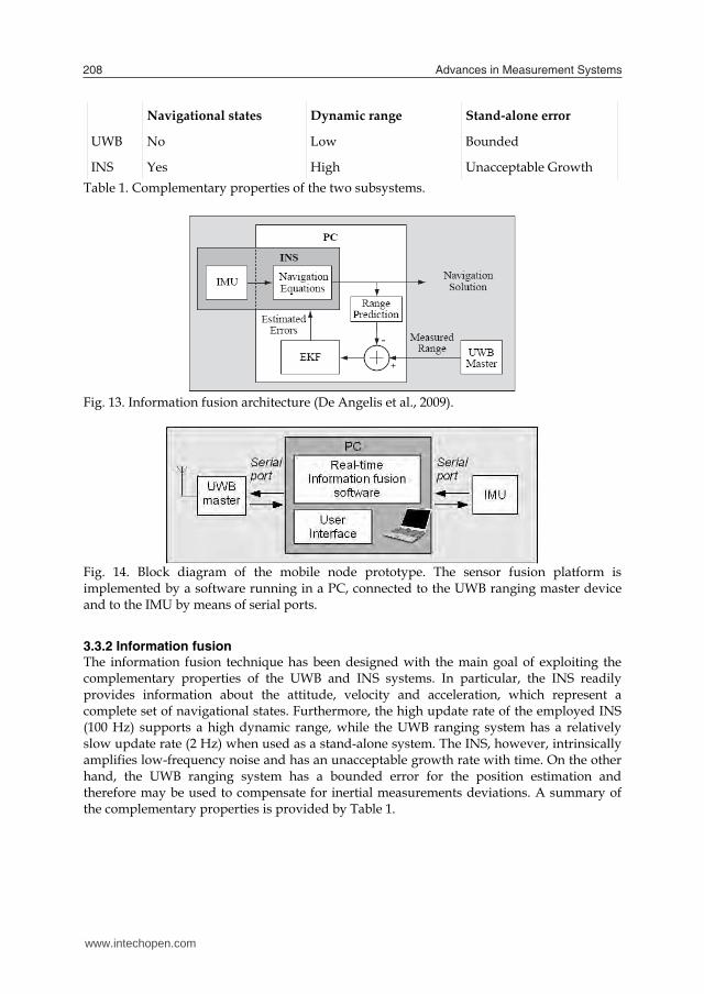
Fig. 12. Inertial Navigation Subsystem architecture (De Angelis et al., 2009b).
3.3.2 Inertial Measurement System The main motivation for integrating an inertial navigation system (INS) with the UWB ranging and positioning devices described in the above sections is to obtain a complete and robust system. In fact, the INS adds information about the attitude of the mobile device, that is the orientation with respect to a reference frame. Furthermore, it provides the knowledge of the velocity and acceleration, thus enabling a complete characterization of the navigation states. Regarding the contribution of the INS to the system's robustness, it can be useful to support the ranging system in those areas where there is insufficient coverage, e.g. there is line-of-sight connection with less than three slaves. In such situations the INS can track the mobile node's position for a limited period of time, as shown in Fig. 11. The INS is composed of two sections: the Inertial Measurement Unit (IMU), an hardware device that houses accelerometers and gyroscopes, and the software component which implements the navigation equations. A detailed illustration of the INS architecture is shown in Fig. 12.
www.intechopen.com
Advances in Measurement Systems208
Table 1. Complementary properties of the two subsystems.
Fig. 13. Information fusion architecture (De Angelis et al., 2009).
Fig. 14. Block diagram of the mobile node prototype. The sensor fusion platform is implemented by a software running in a PC, connected to the UWB ranging master device and to the IMU by means of serial ports.
3.3.2 Information fusion The information fusion technique has been designed with the main goal of exploiting the complementary properties of the UWB and INS systems. In particular, the INS readily provides information about the attitude, velocity and acceleration, which represent a complete set of navigational states. Furthermore, the high update rate of the employed INS (100 Hz) supports a high dynamic range, while the UWB ranging system has a relatively slow update rate (2 Hz) when used as a stand-alone system. The INS, however, intrinsically amplifies low-frequency noise and has an unacceptable growth rate with time. On the other hand, the UWB ranging system has a bounded error for the position estimation and therefore may be used to compensate for inertial measurements deviations. A summary of the complementary properties is provided by Table 1.
Navigational states Dynamic range Stand‐alone error
UWB No Low Bounded
INS Yes High Unacceptable Growth
www.intechopen.com

Experimental Radio Indoor Positioning Systems Based on Round-Trip Time measurement 209
(a) (b) Fig. 15. Histogram of the estimated positions. (a) Reference position: (150 cm, 150 cm), coinciding with the centre of the measurement area. (b) Reference position: (100 cm, 100 cm). Fig. 13 shows a block diagram of the information fusion approach used in the system. The basic principle is a UWB-radio range aided INS architecture, which is developed in a similar manner as a widely adopted solution in outdoor GPS-aided INS. Following such an approach, the INS provides the main navigation solution and when a UWB-radio range measurement is available a range prediction is calculated based upon the current position estimate of the INS. The difference between the measured and predicted range is used as an observation for an Extended Kalman Filter (EKF), implementing a model for how the errors in the INS develop with time and how they relate to errors in the range predictions. The errors are estimated and fed back to the INS. For an exhaustive description of the signal processing algorithm, together with the main issues addressed and the solutions implemented in the system, the reader can refer to (Nilsson et al., 2009). The complete information fusion architecture has been implemented in a prototype, as shown in Fig. 14. In the prototype, the two information sources, namely the UWB ranging system and the INS, are connected to the sensor fusion platform implemented via software in a PC by means of serial ports.
3.3.2 Experimental Characterization In order to experimentally investigate the behaviour of the system and the achievable performance, three kinds of tests have been performed. All the tests have been executed in an indoor environment with line-of-sight signal propagation conditions. Furthermore, as a preliminary phase, all the slave devices were calibrated by performing a series of RTT measurements at known distances, thus obtaining the calibration parameters. Following the preliminary phase, a static position-measuring procedure has been implemented, in which four slave nodes were placed in fixed and known positions at the corners of a 3×3 meter square and a master node was placed in the centre of the same square. During this test, only the UWB ranging system was used, without the fusion with the INS. Repeated individual master-slave distance measurements were collected and the position was estimated following a least squares approach. The results obtained from this measurement set are shown in the histograms of Fig. 15a and 15b. Each of the figures is relative to a different master position, and it can be noticed that the second image shows a larger histogram
www.intechopen.com

Advances in Measurement Systems210
Fig. 16. Low-dynamic test, stand-alone UWB-positioning system. A good agreement between the estimated and the actual trajectory can be observed (De Angelis et al., 2009b). dispersion. This behaviour is consistent with what was expected, since the positioning accuracy is dependent on the geometrical configuration of the master with respect to the slaves and their relative distance. From this point of view, the geometric centre position is the most favourable. By analysing these experiments, it is possible to evaluate the uncertainty associated with the measurement result. Such an evaluation, similarly to the one provided in Section 3.2.1, can be performed using statistical methods, according to the GUM (ISO GUM, 1995). The sample mean and the sample covariance of the experimental estimated positions for the geometrical configuration in Fig. 15a are given by:
157
148sample mean cm
2 10.2 0.5
0.5 11.2sample covariance cm
Therefore, referring to the sample covariance matrix, the “Type A” standard uncertainty can be quantified as 3.3 cm for each spatial coordinate. Subsequently, in order to investigate the position-tracking capability of the UWB ranging platform as a stand-alone system, a second set of measurements have been performed. In this case the master device was moved slowly, at about 0.1 m/s, along a predefined 1×1 m square trajectory. The tracking function has been implemented by means of an algorithm based on the EKF approach. The results of this experiment are shown in Fig. 16, demonstrating a good tracking capability with a maximum deviation of the measured trajectory from the reference path of about 10 cm.
www.intechopen.com

Experimental Radio Indoor Positioning Systems Based on Round-Trip Time measurement 211
(a) (b) Fig. 17. High-dynamic tests, (a) UWB-positioning stand-alone: it can be noticed that overshoot is present, and poor tracking performance is observed. (b) information fusion with INS: no overshoot and better tracking performance has been observed (De Angelis et al., 2009b). The last set of tests consisted in high-dynamic experiments involving the complete system, including the INS and information fusion platform. The experiment was executed on the same trajectory as that of the previous set, but in this case the master was moved quickly, at approximately 1 m/s. Initially the test was performed using the UWB system alone. This test allowed to demonstrate some of the limits of the UWB stand-alone system, mainly caused by the slow update rate, as shown by the overshoot and by the low tracking performance in Fig. 17a. Subsequently, another test using the full system with INS measurement integration was executed in the same experimental conditions. The resulting data is shown in Fig. 17b, demonstrating the considerable performance improvement obtained. In particular, the trajectory overshoot has been eliminated and an overall better tracking behaviour can be observed.
3.4 Future developments Some of the research activities expected in the future involve the improvement of the hardware ranging platform realized so far. In particular, a modification of the baseband pulse generator is currently being studied, with the goal of realizing a system which is fully compliant with both the current European and USA regulations. The step recovery diode generator described in Section 3.1, in fact, provides an output spectrum roughly from DC to 500 MHz. By means of a pulse amplitude‐modulation approach, it is possible to shift this spectrum around the frequency of a carrier signal in the 6 GHz region, therefore operating inside the UWB regulation masks shown in Fig. 1. Furthermore, such a solution could potentially reduce problems associated with the interference from other radio systems, since there is a lower number of narrowband users in the 6 GHz band. Other future developments are aimed at increasing the communication range, coverage and update rate of the system, also considering advances in the information fusion technique and signal processing algorithms.
www.intechopen.com

Advances in Measurement Systems212
(a) (b) Fig. 18. Block diagram of the ZigBee positioning system: (a) Mobile node, (b) Calibrator node. 4. ZigBee ranging system
The principle of operation of the ZigBee system is based on the RTT measurement of Direct Sequence Spread Spectrum (DSSS) modulated pulses, propagating between several transceiver devices. The system-level design, presented in detail in (Santinelli et al., 2009), has been focused on a trade-off between accuracy, cost and synchronization hardware. In particular, it is a low-cost solution, realized by applying some modifications to an existing communication network, without the need for external synchronization hardware, but characterized by a good accuracy for the majority of the applications. Moreover, the implemented system is capable of planar positioning and can easily be extended to 3-D positioning or combined with other ZigBee based applications. A key feature of the realized prototype is its self-calibration capability, designed to remove the bias introduced by the fixed beacons latencies. In fact, in order to properly implement a RTT distance measurement system, it is necessary to estimate and compensate for the responder node latency, as already seen in the previous sections for the UWB device.
4.1 Architecture The ZigBee transceivers used as a basis for the system prototypes are the CC2431 by Chipcon, while the time-interval measuring hardware is the same TDC, the TDC-GP2 by Acam Messelectronic GmbH, used for the UWB system described in the previous sections. The system is comprised of three kinds of devices: the mobile node, the fixed node and the calibrator node. Diagrams for the mobile and calibrator are shown in Fig. 18a and 18b respectively.
www.intechopen.com

Experimental Radio Indoor Positioning Systems Based on Round-Trip Time measurement 213
Fig. 19. Flow-chart of the operation of the ZigBee positioning system. In the mobile node the Chipcon CC2431 device is connected via a Serial Peripheral Interface (SPI) with a DSP (Texas Instrument TMS320C6713) and a TDC. The Chipcon device is used as an RF interface, while the time interval measurement function is performed by the TDC. The DSP is used to program the TDC, to read measurement data through the SPI and to triangulate the mobile node position by properly combining the various RTT measurement results. In particular, the DSP coordinates the communications with slave nodes, by polling them one at a time. The calibrator node has a simpler architecture, without the use of the DSP. By placing this node in a known position, the bias introduced by the fixed nodes can be evaluated by polling them with the calibration node to perform RTT measurements. Finally, each fixed and known position node is a Chipcon CC2431 device, used as pulse repeater. The operation of the system is described in the flow‐chart of Fig. 19. Initially the mobile node programs and initializes its TDC. Then it transmits a packet to a given fixed node, which is received and retransmitted after a certain delay. The master then receives the retransmitted packet, and the TDC determines the signal RTT by measuring the time interval occurring between the transitions of its Start and Stop input signals. By repeating this procedure for a set of fixed nodes, and using calibration data, the mobile node DSP may determine the unknown position using data fusion techniques.
4.2 Experimental Results The ZigBee positioning system has been experimental validated by implementing two configurations in a LOS environment scarcely affected by multipath. The first one consisted of a network of 6 fixed nodes (beacons), without the self-calibration capability. The second one, having fewer nodes, consisted of the mobile node, the calibration node, and a cell of 3 beacons. Experimental results obtained using the first setup are reported in Fig. 20. The white square represents the actual node, the 6 black squares are the fixed beacons, and the points represent the estimated positions. Each position measurement has been obtained by averaging 500 RTT measurements for each fixed position node. The latency of a single beacon was manually evaluated, and the obtained result was used to compensate all of the RTT measurements. Subsequently, the triangulation was achieved by applying a Least Mean Square (LMS) fitting approach on a linearised model (Santinelli et al., 2009). By analysing the obtained results, a bias of -0.74 m on the x coordinate and of -0.59 m on the y coordinate have been observed, while the standard deviation is about 0.41 m for both coordinates.
www.intechopen.com

Advances in Measurement Systems214
Fig. 20. Experimental results for the first configuration, without self-calibration feature. (Santinelli et al., 2009). Following this experiment, the second setup was implemented and tested. As a first step, the calibration procedure was performed for each beacon, in order to estimate and compensate for the corresponding latencies. In particular, the average of 500 RTT calibration measurements performed at increasing distances between the calibration node and one of the beacons was calculated. Then, the calibration line was obtained by applying numerical fitting to the measurement results, as shown in Fig. 21a. It can be observed that the RTT increases linearly in the considered range, with a slope of approximately 22.5 ns/m. A possible cause of this behaviour may be the reduced signal-to-noise ratio at the receiver input, inducing increased correlation latencies. Consequently, as the signal propagation contributes to the RTT with a slope of 6.6 ns/m, we may infer that also the detection time varies linearly, with a slope of about 15.9 ns/m. Moreover, the time required to retransmit a detected pulse, which is not dependent on the distance d, is the line intercept point, which is about 888 μs. Measurement results for the second setup are reported in Fig. 21b, where the positions of the various nodes and estimated positions are shown. Similarly to Fig. 20, the white square represents the mobile node, located in (3,3), the 3 filled squares are the fixed beacons, located in (2,1), (4,1), and (1,6) respectively, the white circle is the calibration node, located in (3,6), and the points are measurement results. Again, each position measurement has been performed by averaging 500 RTT measurements per fixed position node. Then, bias removal and range estimation have been performed, using the calibration results obtained for each beacon. Finally, as only 3 fixed beacons were present, a simplified triangulation algorithm was used, obtained by modifying the algorithm which calculates the intersection of 3 circumferences. The measurement results correspond to a standard deviation of 0.2 m and a bias of 0.14 m for the x coordinate, and a standard deviation of 0.16 m and a bias of 0.01 m for the y coordinate. Consequently the results obtained show that, by using self calibration, a system based on a reduced number of beacons may achieve better location accuracy than a larger system without self-calibration capabilities.
www.intechopen.com

Experimental Radio Indoor Positioning Systems Based on Round-Trip Time measurement 215
(a)
(b)
Fig. 21. Experimental results for the second configuration, with self-calibration. (a) Node calibration line. The circles are measurement results, while the straight line has been obtained by fitting. (b) Positioning results, the white square is the actual node position, the black squares are the reference nodes, the white circle is the calibration node and the points are estimated positions. (Santinelli et al., 2009).
4.3 Future developments Some possible developments of this research activity involve the theoretical and experimental study of the performance of RTT-based ranging and positioning techniques for ZigBee systems. Of particular interest is the performance evaluation in multipath and non-line-of-sight channels. A further development is represented by the study and implementation of methods aimed at increasing system immunity to multipath, such as those presented in (Schwarzer et al., 2008). An alternative approach involves the information fusion between the
www.intechopen.com
Advances in Measurement Systems216
RTT and readily-available signal-strength data, in order to identify measurements affected by strong multipath and weight their contribution to LMS fitting. Additionally, multipath components may possibly be identified by performing ZigBee transmissions at different frequencies and by analysing the variations when measuring both the RSS and the RTT.
5. Conclusion
Two indoor positioning systems based on RTT measurement have been presented in this chapter, focusing on a description of the basic principle of operation, main building blocks and experimental evaluations. Regarding the technical performance aspects, as shown by the experimental test results described in the previous sections, the UWB system has the advantage of a higher positioning accuracy. This system, in fact, is capable of measuring position with a standard uncertainty of about 3 cm under favourable conditions, while the ZigBee platform is characterized by an accuracy of about 20 cm. The latter solution, instead, provides an higher communication range, up to the order of magnitude of 100 m, as opposed to the 10 m order provided by the UWB prototypes. Apart from the purely performance-related analysis, it is also possible to perform a more general comparison, considering other aspects. In this regard, the ZigBee system has the advantage of exploiting a pre-existent communication platform. This feature could be of relevance from the point of view of a planning strategy, depending on the specific application. Using this feature, in fact, a fast, robust and convenient data transfer in the wireless sensor network could be provided in addition to the position evaluation. On the other hand, the UWB system, being a non-commercial solution, allows for a greater control of the design aspects and specifications. The additional bandwidth-related benefits associated to the UWB approach must also be taken into account, as discussed in the state of the art section of this chapter.
6. Acknowledgements
This research activity has been partially funded by the research grant COTR09SS provided by “Consorzio per lo Sviluppo Universitario della Provincia di Terni”, whose support the authors gratefully acknowledge.
7. References
Acam messelectronic GmbH, (2007) TDC-GP2 Universal 2 Channel Time-to-Digital Converter Data Sheet. [Online]. Available: http://www.acam.de/fileadmin/ Download/pdf/English/DB_GP2_e.pdf
Blumenthal, J.; Grossmann, R.; Golatowski, F. & Timmermann, D. (2007) Weighted Centroid Localization in ZigBee-based Sensor Networks, IEEE International Symposium Intelligent Signal Processing, WISP, Alcala de Henares, Oct.3-5, 2007, ISBN: 978-1-4244-0829-0
Corral, P.; Pena, E.; Garcia, R.; Almenar, V.; de C. Lima, A.C. (2008) Distance Estimation System based on ZigBee, Proceedings of 11th IEEE International Conference on Computational Science and Engineering Workshops, CSEWORKSHOPS '08, San Paulo, 16-18 July 2008, pp.405–411, ISBN: 978-0-7695-3257-8
www.intechopen.com

Experimental Radio Indoor Positioning Systems Based on Round-Trip Time measurement 217
Chandrakasan, A.P.; Lee, F.S.; Wentzloff, D.D.; Sze, V.; Ginsburg, B.P.; Mercier, P.P.; Daly, D.C. & Blazquez, R. (2009) Low-Power Impulse UWB Architectures and Circuits, Proceedings of the IEEE , Vol. 97, No. 2 (Feb. 2009), pp. 332–352, ISSN: 0018-9219
Cho, H.; Kang, M.; Park, J.; Park, B. & Kim, H. (2007) Performance Analysis of Location Estimation Algorithm in ZigBee Networks using Received Signal Strength, Proceeding of 21st IEEE International Conference on Advanced Information Networking and Applications Workshops AINAW'07. Niagara Falls, Ont., CA. ISBN: 978-0-7695-2847-2
Dardari, D.; Conti, A.; Ferner, U.; Giorgetti, A.; Win, M.Z. (2009) Ranging With Ultrawide Bandwidth Signals in Multipath Environments, Proceedings of the IEEE , Vol. 97, No. 2, (Feb. 2009), pp. 404-426, ISSN: 0018-9219
De Angelis, A.; Dionigi, M.; Moschitta, A.; Giglietti, R. & Carbone, P. (2008a) An experimental UWB distance measurement system, Proceedings of the IEEE International Instrumentation and Measurement Technology Conference, I2MTC, pp. 1016-1020, ISBN: 1-4244-1541-1, Victoria, BC, Canada, 12-15 May 2008, IEEE, Piscataway, NJ, USA
De Angelis, A.; Dionigi, M.; Moschitta, A.; Giglietti, R. & Carbone, P. (2009a). Characterization and Modeling of an Experimental UWB Pulse-Based Distance Measurement System,” IEEE Transactions on Instrumentation and Measurement, Vol. 58, No. 5, (May 2009), pp. 1479–1486, ISSN: 0018-9456
De Angelis, A.; Nilsson, J.O.; Skog, I.; Händel, P. & Carbone, P. (2009b) Indoor positioning by ultra wide band radio aided inertial navigation, Proceedings of the XIX IMEKO World Congress, Lisbon, Portugal, Sept. 6-11 2009
De Angelis, A.; Dionigi, M.; Moschitta, A. & Carbone, P. (2009c) A Low-Cost Ultra-Wideband Indoor Ranging System, IEEE Transactions on Instrumentation and Measurement, Vol. 58, No. 12 (December 2009), pp. 3935-3942, ISSN: 0018-9456.
Di Benedetto, M.G.; Kaiser, T.; Molisch, A.F.; Oppermann, I.; Politano, C. & Porcino, D. (2006) UWB Communication Systems: A Comprehensive Overview. EURASIP book series on signal processing and communications, Volume 5. Hindawi Publishing Corporation, ISBN 977-5945-10-0
ETSI, European Telecommunications Standards Institute (2008) Electromagnetic compatibility and radio spectrum matters (ERM); ultra wideband (UWB) technologies for communication purposes; ETSI EN 302 065, Feb. 2008
Federal Communications Commission, FCC (2002) Revision of part 15 of the commission’s rules regarding ultra-wideband transmission systems. Report and order, FCC 02 48, Apr. 2002
Fontana, R.J. (2004) Recent system applications of short-pulse ultra-wideband (UWB) technology, IEEE Transactions on Microwave Theory and Techniques, vol.52, no.9, (Sept. 2004), pp. 2087-2104, ISSN: 0018-9480
Gezici, S.; Tian, Z.; Giannakis, G.B.; Kobayashi, H.; Molisch, A.F.; Poor, H.V. & Sahinoglu, Z. (2005) Localization via ultra-wideband radios: a look at positioning aspects for future sensor networks, IEEE Signal Processing Magazine, Vol. 22, No. 4, (July 2005) pp. 70-84, ISSN: 1053-5888
www.intechopen.com
Advances in Measurement Systems218
Hirschler-Marchand, P.R.; Hatke, G.F. (2002) Superresolution techniques in time of arrival estimation for precise geolocation, Conference Record of the Thirty-Sixth Asilomar Conference on Signals, Systems and Computers, pp. 1272-1277, ISBN: 0-7803-7576-9, Asilomar, CA, USA, 3-6 Nov. 2002, IEEE, Piscataway, NJ, USA
Hirt, W. (2007) The european UWB radio regulatory and standards framework: Overview and implications, Proc. IEEE International Conference on Ultra-Wideband (ICUWB), pp. 733–738, 24–26 Sept. 2007, Singapore, ISBN: 978-1-4244-0521-3
IEEE 802.15.4a-2007, IEEE Standard for Information Technology - Telecommunications and information exchange between systems - Local and metropolitan area networks - specific requirement Part 15.4: Wireless Medium Access Control (MAC) and Physical Layer (PHY) Specifications for Low-Rate Wireless Personal Area Networks (WPANs), ISBN: 978-0-7381-5538-8
ISO GUM (1995), Guide to the expression of uncertainty in measurement, International Organization for Standardization, Genève, Switzerland, 1995.
Kandoian, A. G. (1945) Broad Band Antenna, U.S. Patent n. 2368663, February 1945. Kumar, N. & Buehrer, R. M. (2008) The ultra wideband WiMedia standard [standards in a
nutshell], IEEE Signal Processing Magazine, vol. 25, No. 5 (Sept. 2008), pp. 115–119, ISSN: 1053-5888
Lee, J.Y. & Scholtz, R.A. (2002) Ranging in a dense multipath environment using an UWB radio link, IEEE Journal on Selected Areas in Communications, vol. 20, No. 5, pp. 1677-1683, ISSN: 0733-8716
Liu, H.; Darabi, H.; Banerjee, P.; Liu, J. (2007) Survey of Wireless Indoor Positioning Techniques and Systems, IEEE Transactions on Systems, Man, and Cybernetics, Part C: Applications and Reviews, , Vol. 37, No. 6, (Nov. 2007), pp.1067-1080, ISSN: 1058-6393
Low, Z. N.; Cheong, J. H.; Law, C. L.; Ng, W. T. & Lee, Y. J. (2005) Pulse detection algorithm for line-of-sight (LOS) UWB ranging applications, IEEE Antennas and Wireless Propagation Letters, vol. 4, pp. 63–67, ISSN: 1536-1225
Mahfouz, M. R.; Zhang, C.; Merkl, B. C.; Kuhn, M. J. & Fathy, A. E. (2008) Investigation of High-Accuracy Indoor 3-D Positioning Using UWB Technology, IEEE Transactions on Microwave Theory and Techniques, vol. 56, No. 6 (June 2008), pp. 1316–1330, ISSN: 0018-9480
Molisch, A.F. (2005) Ultrawideband propagation channels-theory, measurement, and modeling, IEEE Transactions on Vehicular Technology, Vol. 54, No. 5, (Sept. 2005), pp. 1528-1545, ISSN: 0018-9545
Molisch, A.; Balakrishnan, K.; Chong, C.; Emami, S.; Fort, A.; Karedal, J.; Kunisch, J.; Schantz, H.; Schuster, U. & Siwiak, K. (2005) IEEE 802.15.4a channel model - final report,” tech. rep., IEEE 802.15.04-0662-02-004a.
Nilsson, J.O.; De Angelis, A.; Skog, I.; Carbone, P. & Händel, P. (2009) Signal processing issues in indoor positioning by ultra wide band radio aided inertial navigation, Proceedings of the 17th European Signal Processing Conference, EUSIPCO, August 24-28, Glasgow, Scotland
Oh, M.K.; Park, J.H. & Kim, J.Y. (2009) IR-UWB packet-based precise ranging system for u-Home networks, IEEE Transactions on Consumer Electronics, vol. 55, no. 1 (Feb. 2009), pp. 119-125, ISSN: 0098-3063
Pahlavan, K.; Li, X. & Makela, J.P. (2002) Indoor geolocation science and technology, IEEE Communications Magazine, Vol. 40, No. 2 (Feb. 2002), pp. 112 – 118, ISSN: 0163-6804
www.intechopen.com

Experimental Radio Indoor Positioning Systems Based on Round-Trip Time measurement 219
Phan, T.A; Lee, J.; Krizhanovskii, V.; Han, S.K. & Lee, S.G. (2007) A 18-pJ/Pulse OOK CMOS Transmitter for Multiband UWB Impulse Radio, IEEE Microwave and Wireless Components Letters, Vol. 17, No. 9 (Sept. 2007), pp. 688-690, ISSN: 1531-1309
Rantakokko, J.; Händel, P.; Eklöf, F.; Boberg, B.; Junered, M.; Akos, D.; Skog, I.; Bohlin, H.; Neregård, F.; Hoffmann, F.; Andersson, D.; Jansson, M.; Stenumgaard, P. (2007) Positioning of emergency personnel in rescue operations - possibilities and vulnerabilities with existing techniques and identification of needs for future R&D, Technical Report TRITA-EE 2007:037, Royal Institute of Technology, Stockholm, Sweden, July 2007. [Online]. Available: http://www.ee.kth.se.
Santinelli, G.; Giglietti, R. & Moschitta, A. (2009) Self-calibrating indoor positioning system based on ZigBee Devices, Proceedings of the IEEE International Instrumentation and Measurement Technology Conference, I2MTC, pp. 1205 – 1210, ISBN: 978-1-4244-3352-0 Singapore, 5-7 May 2009, IEEE, Piscataway, NJ, USA
Schwarzer, S.; Vossiek, M.; Pichler, M. & Stelzer, A. (2008) Precise distance measurement with IEEE 802.15.4 (ZigBee) devices, IEEE Radio and Wireless Symposium, Orlando, FL, 22-24 Jan. 2008, pp. 779 – 782, ISBN: 978-1-4244-1463-5
Sim, S.; Kim, D.W.; Hong, S. (2009) A CMOS UWB Pulse Generator for 6–10 GHz Applications, IEEE Microwave and Wireless Components Letters, Vol. 19, No. 2 (Feb. 2009), pp. 83-85, ISSN: 1531-1309
Stoica, L.; Rabbachin, A.; Repo, H.O.; Tiuraniemi, T.S. & Oppermann, I. (2005) An ultrawideband system architecture for tag based wireless sensor networks, IEEE Transactions on Vehicular Technology, vol. 54, no. 5 (Sept. 2005), pp. 1632–1645, ISSN: 0018-9545
Terada, T.; Yoshizumi, S.; Muqsith, M.; Sanada, Y. & Kuroda, T. (2006) A CMOS ultra-wideband impulse radio transceiver for 1-mb/s data communications and ±2.5-cm range finding, IEEE Journal of Solid-State Circuits, Vol. 41, No. 4 (April 2006), pp. 891-898, ISSN: 0018-9200
Time Domain Corporation (2009) PulsON P220 Reference Design. [Online]. Available: http://www.timedomain.com/products/P220aRD.pdf
UbiSense (2009), UWB location system Fact Sheet. [Online]. Available: http://www.ubisense.net/pdf/fact-sheets/products/software/Precise-Location-
EN090624.pdf WiMedia Alliance (2009) [Online], Available: http://www.wimedia.org Win, M.Z. & Scholtz, R.A. (1998) Impulse radio: How it works, IEEE Communication Letters,
Vol. 2, No. 2 (Feb. 1998). IEEE, Piscataway, NJ, USA Wireless USB (2007) USB Implementers Forum, “Wireless USB Specification Revision 1.0.”
[Online]. Available: http://www.usb.org/developers/wusb Wymeersch, H.; Lien, J. & Win, M.Z. (2009) Cooperative Localization in Wireless Networks,
Proceedings of the IEEE, Vol. 97, No. 2 (Feb. 2009), pp. 427-450, ISSN: 0018-9219 Zebra Enterprise Solutions, Multispectral Solutions, (2009), Sapphire DART Real-Time
Location System data sheet [Online], Available: http://zes.zebra.com/pdf/ products-datasheets/ds_sapp_tech.pdf
Zhang, J.; Orlik, P.V.; Sahinoglu, Z.; Molisch, A.F. & Kinney, P. (2009) UWB Systems for Wireless Sensor Networks, Proceedings of the IEEE, Vol. 97, No. 2 (Feb. 2009), pp. 313–331, ISSN: 0018-9219
ZigBee Alliance (2007) ZigBee Specification r17, October 19th, 2007. [Online]. Available: http://www.zigbee.org
www.intechopen.com

Advances in Measurement Systems220
www.intechopen.com

Advances in Measurement SystemsEdited by Milind Kr Sharma
ISBN 978-953-307-061-2Hard cover, 592 pagesPublisher InTechPublished online 01, April, 2010Published in print edition April, 2010
InTech EuropeUniversity Campus STeP Ri Slavka Krautzeka 83/A 51000 Rijeka, Croatia Phone: +385 (51) 770 447 Fax: +385 (51) 686 166www.intechopen.com
InTech ChinaUnit 405, Office Block, Hotel Equatorial Shanghai No.65, Yan An Road (West), Shanghai, 200040, China
Phone: +86-21-62489820 Fax: +86-21-62489821
How to referenceIn order to correctly reference this scholarly work, feel free to copy and paste the following:
Alessio De Angelis, Antonio Moschitta, Peter Handel and Paolo Carbone (2010). Experimental Radio IndoorPositioning Systems Based on Round-Trip Time Measurement, Advances in Measurement Systems, Milind KrSharma (Ed.), ISBN: 978-953-307-061-2, InTech, Available from: http://www.intechopen.com/books/advances-in-measurement-systems/experimental-radio-indoor-positioning-systems-based-on-round-trip-time-measurement