experimental investigation on a controllable colloidal
TRANSCRIPT

J-STAGE Advance Publication date : 21 April, 2015Paper No.14-00512
© 2015 The Japan Society of Mechanical Engineers[DOI: 10.1299/mej.14-00512]
Vol.2, No.3, 2015Bulletin of the JSME
Mechanical Engineering Journal
0123456789
Experimental investigation on a controllable colloidal damper for vehicle suspension
Barenten SUCIU* *Department of Intelligent Mechanical Engineering, Fukuoka Institute of Technology
3-30-1 Wajiro-Higashi, Higashi-ku, Fukuoka 811-0295, Japan E-mail: [email protected]
Abstract In this paper, a controllable colloidal damper designed to work as a vehicle suspension is experimentally investigated. In order to control the damping properties (dissipated energy and damping coefficient) as well as the elastic characteristic (spring constant) of a colloidal damper, the pressurization level inside the cylinder has to be dynamically adjusted by using a pressure controlling device. Concretely, a pumping device in communication with the cylinder, able to force the working liquid to flow into and to flow out from the cylinder is employed. In this way, a controllable parameter, called initial pressure, is adjusted to achieve ideal comfort conditions for the vehicle’s passengers. First, the working principle, the main components, the model of vibration and the control system of a controllable colloidal damper are explained. Using some illustrative hysteresis change diagrams, variation of the dissipated energy, damping coefficient and spring constant versus the initial pressure is phenomenologically interpreted. Experimentally obtained results are used to validate the phenomenological model, and then to evaluate the sensitivity of the proposed system. Since the experimentally obtained damping ratio fluctuation (up to 153 %), is larger than the required change of damping ratio for Kelvin-Voigt and Maxwell suspensions (133 % and 100 %, respectively), one concludes that the proposed controllable colloidal damper has the ability to accommodate real application.
Key words : Vehicle suspension, Nano-damping, Control, Hydraulic system, Dynamic pressurization
1. Introduction
The usually employed vehicle suspension is consisted of a helical compression spring and a hydro-pneumatic
damper. When such suspension receives an impact, the helical spring is firstly compressed, and thereby absorbs the mechanical energy of impact. Then, during spring extension, the absorbed energy is transferred to the hydro-pneumatic damper, which, through the well-known mechanism of fluid friction, “dissipates” the shock energy by converting it into heat that is finally transferred to the surrounding environment. Thus, the helical compression spring is an indispensable element that provides for the necessary restoring force.
Recently, colloidal dampers were proposed as oil-free absorbers for vehicle suspension (Suciu and Tobiishi, 2012; Suciu and Buma, 2012). Thus, oil is replaced by a colloid, i.e., a mixture of water and water-repellent nanoporous particles of silica (artificial sand with controlled architecture), to obtain an ecological hydraulic absorber with high dissipative performances. In the case of a colloidal suspension, since water naturally exudes from the water-repellent silica matrix at decompression, the restoring force is intrinsically achieved, and the compression helical spring can be omitted (Suciu and Tobiishi, 2012). In this way, structural simplification, accompanied by a compact and lighter design can be achieved for the suspension of a certain vehicle (Suciu and Buma, 2012).
Conventional colloidal damper is a passive device, i.e., it is designed to have constant damping and elastic characteristics. However, in order to efficiently dissipate the energy of shock and/or vibration caused by an external excitation, for instance, the displacement excitation caused by the road roughness in the case of a vehicle suspension or the excitation force of an earthquake in the case of an anti-seismic system, it is necessary to adjust the damping and elastic characteristics of a colloidal damper, and in this way to achieve ideal comfort conditions for the passengers of a
1
Received 4 December 2014

2
Suciu, Mechanical Engineering Journal, Vol.2, No.3 (2015)
© 2015 The Japan Society of Mechanical Engineers[DOI: 10.1299/mej.14-00512]
vehicle, or maximal safety conditions for a building, structure, etc. In order to eliminate the drawbacks of passive colloidal dampers, recently controllable colloidal dampers were
proposed (Suciu, 2008, 2010a and 2010b). Thus, in order to control the damping and elastic characteristics of a colloidal damper, the pressurization level inside the cylinder has to be dynamically adjusted by using a pressure controlling device. Various systems able to control the dynamic pressure inside the cylinder were proposed, as follows: a pumping device in communication with the cylinder, able to force the working liquid to flow into, and to flow out from the cylinder; an oscillator able to produce elastic waves and in this way to control the acoustic pressure applied to the porous body, to the working liquid, or to the cylinder; a surface tension controlling device able to adjust the surface tension of at least one of the porous body and the working liquid, and in this way to control the capillary pressure inside the cylinder; a diameter controlling device able to adjust the inner diameter of the pores of the porous body, and in this way to control the capillary pressure inside the cylinder, etc. (Suciu, 2008, 2010a and 2010b; Suciu et al., 2009, 2010).
In this paper, a controllable colloidal damper designed to work as a vehicle suspension is experimentally investigated. In order to control the damping and elastic characteristic, a pumping device in communication with the cylinder, able to force the working liquid to flow into and to flow out from the cylinder is employed. In this way, a controllable parameter, called initial pressure, is adjusted to achieve ideal comfort conditions for the vehicle’s passengers. First, the working principle, the main components, the model of vibration and the control system of a controllable colloidal damper are explained. Using some illustrative hysteresis change diagrams, variation of the dissipated energy, damping coefficient and spring constant versus the initial pressure is phenomenologically interpreted. Experimentally obtained results are used to validate the phenomenological model, and then to evaluate the sensitivity of the proposed system. Based on such theoretical and experimental approach, the necessary magnitude of the dynamic pressure fluctuation to achieve a controllable colloidal damper with practical applications is clarified.
2. Nomenclature
C Damping coefficient, )/( 2
VSE [Ns/m]
E Dissipated energy through colloidal effect, dSSpD )(25.0 2 [J]
f Frequency, [Hz] F Force, pD225.0 [N] K Spring constant, [N/m] m Sprung mass, [kg]
bM Mass of the vehicle’s body, [kg]
wM Wheel mass, [kg] p Pressure, [Pa]
0p Initial pressure, [Pa]
cp Pressurization (compression) pressure, [Pa]
mp Mean pressure, [Pa]
rp Depressurization (decompression) pressure, [Pa] S Stroke, [m]
0S Start position, [m]
VS Amplitude of the displacement excitation, [m] t Time, [s]
prT , Transmissibility of a parallel Kelvin-Voigt vehicle suspension at resonance, [-]
srT , Transmissibility of a serial Maxwell vehicle suspension at resonance, [-] V Vehicle’s travel velocity, [m/s] Wavelength of the road roughness, [m] Circular frequency, /22 Vf [rad/s] Damping ratio, mKC /5.0 [-]
, Sensitivity of the proposed controllable colloidal damper, [J/MPa], [-]
2.1 Subscripts max Maximum
2

2
Suciu, Mechanical Engineering Journal, Vol.2, No.3 (2015)
© 2015 The Japan Society of Mechanical Engineers[DOI: 10.1299/mej.14-00512]
t Tire 61 Subscripts connected to Figs. 3.a-3.f
3. Working principle of the proposed controllable colloidal damper
Figure 1 illustrates the schematic view and the vibration model of a controllable colloidal damper, and Fig. 2 shows
a photograph of the constructed colloidal damper and its associated pressure controlling system. As presented in Fig. 1, the proposed controllable colloidal damper is designed to work as a vehicle suspension and
it is consisted of a cylinder, a piston guided and supported by the cylinder during its reciprocating movement, and defining a closed space in association with the cylinder, a porous body (silica particles) having a large number of pores, and being housed in the closed space, and a working liquid (water, solutions of water and antifreeze agent, etc.) contained in the closed space together with the porous body, the working liquid flowing into the pores of the porous body during pressurization, and flowing out from the pores of the porous body during depressurization, and a pressure controlling device to adjust the pressure in the closed space.
Inside the cylinder, a filter is provided as a partition wall that divides the closed space into two closed spaces, in the upper and lower part of the filter. While the upper closed space contains only the working liquid, the porous particles of silica are housed only in the lower closed space, which is situated in the opposite side of the piston. Such filter has a large number of pores each having a diameter, ranging from about 0.1 micrometer to about 10 micrometers, smaller than the average outer diameter of the porous particles of silica. In this way, the porous bodies are not allowed to pass through, but only the working liquid is allowed to pass through the filter’s pores. Consequently, the pores of the filter prevent the porous particles to penetrate into a frictional region that occurs at the relative movement between the piston and the cylinder, but allow the working liquid to freely move between the upper and lower closed spaces. Note that the presence of the filter is not required for the dynamic control of the initial pressure, but to insure a sufficiently long lifetime for the proposed controllable colloidal damper (Suciu and Yaguchi, 2009).
Fig.1 Schematic view and vibration model Fig.2 Photograph of the colloidal damper and associated of the controllable colloidal damper. pressure controlling system.
Concretely, the pressure controlling device is a pumping device (hydro-pneumatic pump) in communication with
the cylinder, and it is able to force the working liquid to flow into and to flow out from the cylinder. In this way, a controllable parameter, called initial pressure ( 0p ), is adjusted to achieve ideal comfort conditions for the vehicle’s passengers. Such hydro-pneumatic pump is a high-pressure piston-type pump for water as working liquid, which is pneumatically driven. For this reason also a low-pressure air compressor, not shown in Fig. 1 but presented on Fig. 2, is necessary to drive the water pump. The servo-valve shown schematically in Fig. 1 is achieved as a relatively complex hydraulic system (see Fig. 2), and it is used to control the volume or the pressure of the working liquid flowing into and flowing out from the cylinder, and consequently, it is a valve which dynamically controls the initial pressure.
Proposed controllable colloidal damper further includes a pressure sensor to measure the pressure inside the cylinder, and three accelerometers to measure the acceleration at three distinct locations: cylinder, piston, and driver’s
Colloidal damper
Road
Driver seat
Con
trol
ler
Feed-back
Servo-valve
Hyd
ro-p
neum
atic
pum
p
Accelerometer
Pressuresensor
Laptop
Hydraulic system
Generator
Measurement equipment
Interface
Aircompressor
Voltagestabilizer
Colloidal damper (Frontal suspension)
Rough road
wM
tKtC
bM
C
K
Body
Tire
Colloidal damper
Road
Driver seat
Con
trol
ler
Feed-back
Servo-valve
Hyd
ro-p
neum
atic
pum
p
Accelerometer
Pressuresensor
Road
Driver seat
Con
trol
ler
Feed-back
Servo-valve
Hyd
ro-p
neum
atic
pum
p
Accelerometer
Pressuresensor
Laptop
Hydraulic system
Generator
Measurement equipment
Interface
Aircompressor
Voltagestabilizer
Colloidal damper (Frontal suspension)
Rough road
wM
tKtC
bM
C
K
Body
Tire
3

2
Suciu, Mechanical Engineering Journal, Vol.2, No.3 (2015)
© 2015 The Japan Society of Mechanical Engineers[DOI: 10.1299/mej.14-00512]
seat of the vehicle. In this way, pressure inside the damper’s cylinder and accelerations necessary to evaluate the level of comfort of the tested vehicle are continuously monitored, they representing INPUT signals for the associated controller (see Fig. 1). Thus, the controller is able to control the operation of the servo-valve and the pumping device in accordance with the received values of the pressure and accelerations.
When a conventional passive colloidal damper is used for a vehicle suspension, spring constant and damping coefficient cannot be adjusted according to the displacement excitation produced by the actual road surface. Since it is not possible to efficiently dissipate the energy of vibration, the ride comfort might become poor, and accordingly, over long travel distances the passengers might suffer some discomfort sensation. However, the proposed controllable colloidal damper includes a controller used to adjust the initial pressure inside the cylinder, and thereby the damping and elastic characteristics are dynamically adjusted in such a way that the ride comfort of the vehicle is maintained in a comfortable range, regardless the quality of the road. Such controller is consisted of a computer executing several programs, such as the module for processing the measured data, the module for computing the damping coefficient and spring constant, the module for computing the ride comfort, the feedback control module, etc. Thus, based on the INPUT values of the measured pressure and accelerations, the controller calculates in real time the appropriate values of the damping coefficient and the spring constant necessary to assure an ideal ride comfort level of the vehicle. Then, the control program calculates the initial pressure 0p necessary to achieve the desired damping coefficient and spring constant. Next, the feedback control module produces an OUTPUT signal which is the difference between the initial pressure measured by the pressure gauge and the initial pressure calculated by the control program, and this signal transmitted from the controller becomes an INPUT signal for the high-pressure pump and servo-valve. Thus, it becomes possible to automatically control the discharge of the pump and to automatically control the open/close action of the servo-valve, and in this way it is possible to adjust the initial pressure to a desired initial pressure.
4. Required change of damping ratio for a controllable suspension
4.1 Required change of damping ratio for a controllable Kelvin-Voigt suspension
Designer of a passive Kelvin-Voigt suspension (dashpot C and elastic element K connected in parallel) has to
compromise between two opposite requirements: on one hand, to provide large enough damping at lower excitation frequencies, in order to reduce the resonant peak, and, on the other hand, to provide low enough damping at higher excitation frequencies, in order to minimize the vibration transmissibility from the rough road to the vehicle’s body (Suciu and Tobiishi, 2012). Since the vibration transmissibility at the resonant peak prT , is depending only on the damping ratio ( 2
, /25.01 prT ), such compromise is usually achieved by selecting 15.0 (see Table 1). It is important to note that, for a Kelvin-Voigt suspension the following design range of 10 should be
satisfied for the damping ratio. Traditional way to reduce the damping at higher frequencies in a passive manner is to replace the dashpot by a
Maxwell unit consisted of a spring and dashpot connected in series (Suciu et al., 2012). Another traditional way is to increase the damping at the resonant peak in an active manner. Since the effect on transmissibility reduction is quite modest for damping augmentation in the range of 0.35-0.5 (see Table 1), one concludes that a reasonable damping change requirement for an actively controlled damper is as follows: damping ratio change from 0.15 (usual passive suspension) to 0.35 (see Table 1). Under such damping ratio change of / 133 % the resonant peak reduces to half. For the above-mentioned reasons, in this work, for an actively controlled colloidal damper, modeled as a Kelvin-Voigt suspension, the required change of damping ratio is considered as: / 133 %.
Table 1 Variation of the vibration transmissibility at the resonant peak prT , versus the damping ratio
(Kelvin-Voigt suspension).
Damping ratio, [-] 0.10 0.15 0.20 0.25 0.30 0.35 0.40 0.45 0.50
Vibration transmissibility, prT , [-] 5.1 3.5 2.7 2.2 1.9 1.7 1.6 1.5 1.4
4.2 Required change of damping ratio for a controllable Maxwell suspension
As illustrated in Fig. 1, the so-called Maxwell model, consisted of a dashpot C and an elastic element
4

2
Suciu, Mechanical Engineering Journal, Vol.2, No.3 (2015)
© 2015 The Japan Society of Mechanical Engineers[DOI: 10.1299/mej.14-00512]
K connected in series (Suciu et al., 2012), is more-likely to be an appropriate model of vibration for the proposed colloidal damper. Similar to Kelvin-Voigt suspension, also in this case, the vibration transmissibility at the resonant peak srT , is depending only on the damping ratio ( 2, srT ), but it is important to note that for a Maxwell suspension a different design range of 25.0 should be satisfied for the damping ratio. However, in order to maintain the vibration transmissibility to values comparable to those corresponding to Kelvin-Voigt suspension (see Table 1), the damping ratio of Maxwell suspension is usually limited by selecting 5.2 and more frequently by selecting 75.1 (see Table 2).
In the case of a Maxwell suspension, in order to reduce the damping ratio at the resonant peak in an active manner, similar to the case of a Kelvin-Voigt suspension, a reasonable damping ratio change requirement can be considered as follows: damping ratio change from 1.75 (usual passive suspension) to 0.875 (see Table 2). Under such damping ratio change of / 100 % the resonant peak reduces to half. For the above-mentioned reasons, in this work, for a controllable colloidal damper modeled as a Maxwell suspension, the required change of damping ratio is considered as: / 100 %.
Table 2 Variation of the vibration transmissibility at the resonant peak srT , versus the damping ratio
(Maxwell suspension).
Damping ratio, [-] 2.5 1.75 1.25 1.00 0.875 0.75 0.50 0.25
Vibration transmissibility, srT , [-] 5.0 3.5 2.5 2.0 1.75 1.5 1.0 0.5
5. Phenomenological interpretation for the change of damping and elastic characteristics
In this Section using some illustrative hysteresis change diagrams, variation of the dissipated energy, damping
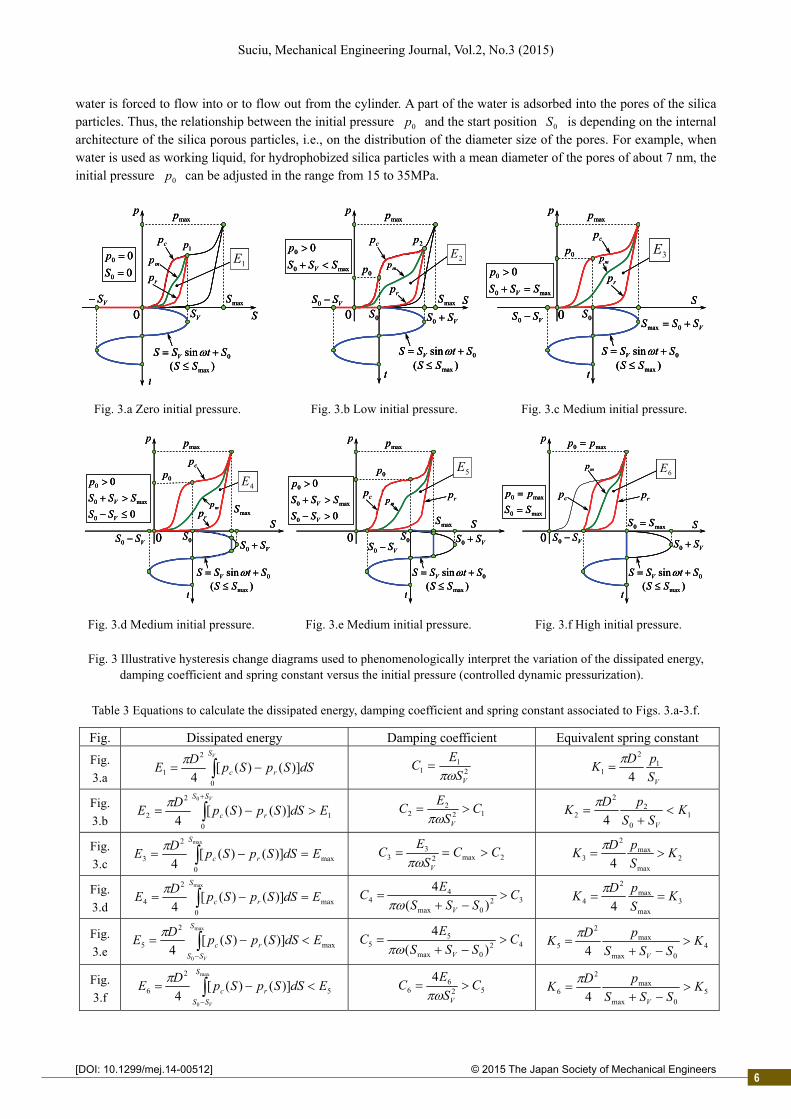
coefficient and spring constant versus the initial pressure is phenomenologically interpreted (see Fig. 3 and Table 3). Neglecting the frictional effects, which are depending on the contact conditions between the piston and the
packing, between the piston and the cylinder, as well as between the piston and the packing cover, the maximum dissipated energy maxE and the maximum damping coefficient maxC produced through colloidal effect (see for instance the black hysteresis corresponding to maxp and maxS in Fig. 3.a) can be calculated as:
2max
max
0
2
max ;)]()([4
max
V
S
rc S
ECdSSpSp
DE
(1)
Here S is the piston stroke or the displacement excitation, VS is the amplitude of the displacement excitation, is the circular frequency, D is the piston diameter, and cp ( rp ) is the internal pressure during pressurization (depressurization). Since VS usually equals the amplitude of the road roughness, it occurs as an uncontrollable parameter. Since the circular frequency /2 V is depending on the travel velocity V of the vehicle and on the wavelength of the road roughness, it is also an uncontrollable parameter.
Even a colloidal damper has large damping ability, when subjected to the rough road excitation tSS V sin without dynamic pressurization (zero initial pressure 00 p in Fig. 3.a), if the amplitude of the displacement excitation is smaller than the maximum stroke ( maxSSV ), only a small part of the vibration energy will be dissipated, as illustrated by the red small hysteresis in Fig. 3.a. However, considering the initial pressure 0p or the corresponding start position 0S as a controllable parameter, under dynamic pressurization ( 00 p in Figs. 3.b-3.f), the rough road excitation 0sin StSS V occurs as displaced over the distance 0S and a large part of the vibration energy will be dissipated if 0p is set to appropriate moderate values (see the red large hysteresis in Figs. 3.c-3.e). A change in the dissipated energy, which is proportional to the area of the hysteresis shown in Fig. 3, is accompanied by a change in the damping coefficient C and also a change in the spring constant K (slope of the green curve corresponding to the mean pressure mp in Fig. 3). Thus, by applying a dynamic pressurization, the dissipative and elastic properties of the colloidal damper can be adjusted.
Proposed controllable colloidal damper is safety designed in such a manner that, under the sinusoidal displacement excitation tSSS V sin0 the internal pressure cannot exceed an imposed maximum pressure ( maxpp ). In other words, the piston stroke cannot exceed the maximum piston stroke ( maxSS ), i.e., truncation of the stroke at maxS is also included in the controller’s program. In order to obtain the ideal computed initial pressure 0p inside the cylinder,
5
2
Suciu, Mechanical Engineering Journal, Vol.2, No.3 (2015)
© 2015 The Japan Society of Mechanical Engineers[DOI: 10.1299/mej.14-00512]
water is forced to flow into or to flow out from the cylinder. A part of the water is adsorbed into the pores of the silica particles. Thus, the relationship between the initial pressure 0p and the start position 0S is depending on the internal architecture of the silica porous particles, i.e., on the distribution of the diameter size of the pores. For example, when water is used as working liquid, for hydrophobized silica particles with a mean diameter of the pores of about 7 nm, the initial pressure 0p can be adjusted in the range from 15 to 35MPa.
Fig. 3.a Zero initial pressure. Fig. 3.b Low initial pressure. Fig. 3.c Medium initial pressure.
Fig. 3.d Medium initial pressure. Fig. 3.e Medium initial pressure. Fig. 3.f High initial pressure.
Fig. 3 Illustrative hysteresis change diagrams used to phenomenologically interpret the variation of the dissipated energy,
damping coefficient and spring constant versus the initial pressure (controlled dynamic pressurization).
Table 3 Equations to calculate the dissipated energy, damping coefficient and spring constant associated to Figs. 3.a-3.f.
Fig. Dissipated energy Damping coefficient Equivalent spring constant
Fig.
3.a VS
rc dSSpSpD
E0
2
1 )]()([4
2
11
VS
EC
VS
pDK 1
2
1 4
Fig.
3.b 1
0
2
2
0
)]()([4
EdSSpSpD
EVSS
rc
122
2 CS
EC
V
1
0
22
2 4K
SS
pDK
V
Fig.
3.c max
0
2
3
max
)]()([4
EdSSpSpD
ES
rc
2max23
3 CCS
EC
V
2max
max2
3 4K
S
pDK
Fig.
3.d max
0
2
4
max
)]()([4
EdSSpSpD
ES
rc
320max
44 )(
4C
SSS
EC
V
3
max
max2
4 4K
S
pDK
Fig.
3.e max
2
5
max
0
)]()([4
EdSSpSpD
ES
SS
rc
V
42
0max
55 )(
4C
SSS
EC
V
4
0max
max2
5 4K
SSS
pDK
V
Fig.
3.f 5
2
6
max
0
)]()([4
EdSSpSpD
ES
SS
rc
V
52
66
4C
S
EC
V
5
0max
max2
6 4K
SSS
pDK
V
0 SmaxS
pmaxp
VS
t
0sin StSS V
cp
rp
)( maxSS
0
0
0
0
S
p
VS
1Emp1p
0SmaxS
pmaxp
VSS 0
0sin StSS V
cp
rp
)( maxSS
max0
0 0
SSS
p
V
0S
t
VSS 0
0p2E
2p
mp
0S
pmaxp
VSS 0
0sin StSS V
cp
rp
)( maxSS
max0
0 0
SSS
p
V
0S
t
VSSS 0max
0p 3Emp
0 SmaxS
pmaxp
VS
t
0sin StSS V
cp
rp
)( maxSS
0
0
0
0
S
p
VS
1Emp1p
0 SmaxS
pmaxp
VS
t
0sin StSS V
cp
rp
)( maxSS
0
0
0
0
S
p
VS
1Emp1p
0SmaxS
pmaxp
VSS 0
0sin StSS V
cp
rp
)( maxSS
max0
0 0
SSS
p
V
0S
t
VSS 0
0p2E
2p
mp
0SmaxS
pmaxp
VSS 0
0sin StSS V
cp
rp
)( maxSS
max0
0 0
SSS
p
V
0S
t
VSS 0
0p2E
2p
mp
0S
pmaxp
VSS 0
0sin StSS V
cp
rp
)( maxSS
max0
0 0
SSS
p
V
0S
t
VSSS 0max
0p 3Emp
0S
pmaxp
VSS 0
0sin StSS V
cp
rp
)( maxSS
max0
0 0
SSS
p
V
0S
t
VSSS 0max
0p 3Emp
0S
pmax0 pp
VSS 0
0sin StSS V
cp rp
)( maxSS
max0
max0
SS
pp
t
VSS 0
max0 SS
6Emp
0S
pmaxp
VSS 0
0sin StSS V
cp
rp
)( maxSS
0
0
0
max0
0
V
V
SS
SSS
p
0S
t
VSS 0
0p
maxS
4E
mp
0S
pmaxp
VSS 0
0sin StSS V
cprp
)( maxSS
0
0
0
max0
0
V
V
SS
SSS
p
0S
t
VSS 0
maxS
0p
mp
5E
0S
pmax0 pp
VSS 0
0sin StSS V
cp rp
)( maxSS
max0
max0
SS
pp
t
VSS 0
max0 SS
6Emp
0S
pmax0 pp
VSS 0
0sin StSS V
cp rp
)( maxSS
max0
max0
SS
pp
t
VSS 0
max0 SS
6Emp
0S
pmaxp
VSS 0
0sin StSS V
cp
rp
)( maxSS
0
0
0
max0
0
V
V
SS
SSS
p
0S
t
VSS 0
0p
maxS
4E
mp
0S
pmaxp
VSS 0
0sin StSS V
cp
rp
)( maxSS
0
0
0
max0
0
V
V
SS
SSS
p
0S
t
VSS 0
0p
maxS
4E
mp
0S
pmaxp
VSS 0
0sin StSS V
cprp
)( maxSS
0
0
0
max0
0
V
V
SS
SSS
p
0S
t
VSS 0
maxS
0p
mp
5E
0S
pmaxp
VSS 0
0sin StSS V
cprp
)( maxSS
0
0
0
max0
0
V
V
SS
SSS
p
0S
t
VSS 0
maxS
0p
mp
5E
6

2
Suciu, Mechanical Engineering Journal, Vol.2, No.3 (2015)
© 2015 The Japan Society of Mechanical Engineers[DOI: 10.1299/mej.14-00512]
Figures from 3.a to 3.f together with the associated Table 3, illustrate variation of the damping and elastic characteristics versus the initial pressure. Thus, the initial pressure is equal to zero in Fig. 3.a ( 00 p and 00 S ), the initial pressure is low in Fig. 3.b ( 00 p and max0 SSS V ), the initial pressure is medium in Fig. 3.c ( 00 p and max0 SSS V ), the initial pressure is medium in Fig. 3.d ( 00 p and max0 SSS V as well as 00 VSS ), the initial pressure is also medium in Fig. 3.e ( 00 p and max0 SSS V as well as 00 VSS ), and the initial pressure is high in Fig. 3.f ( max0 pp and max0 SS ). Figures from 3.d to 3.f are constructed by taking into account the safety condition of restricted pressure ( maxpp ) or stroke ( maxSS ). Table 3 illustrates the equations necessary to calculate the dissipated energy, damping coefficient and spring constant associated to Figs. 3.a-3.f, and also the relative comparison between values corresponding to different cases of study (e.g., 4max321 EEEEE as well as
max456 EEEE ). Based on the results presented in Fig. 3 and Table 3, the following shapes for the diagrams expressing variation of the dissipated energy (see Fig. 4), damping coefficient (see Fig. 5) and spring constant (see Fig. 6) versus the initial pressure can be suggested for constant (fixed) excitation frequency.
One observes that the characteristics of pressure (see the largest hysteresis loop in Figs. 3.a-f) during pressurization ( cp ) and depressurization ( rp ) are very important for the estimation of the phenomenological model (see Figs. 4-5). These characteristics depend on the internal architecture of the silica porous particles, i.e., on the distribution of the diameter size of the pores, on the type of hydrophobic coating, and also on the associated liquid. Since such distributions cannot be accurately predicted by theoretical models, they are experimentally obtained through water porosimetry techniques. In principle, by appropriately designing the inner architecture of the silica particles, various shapes of the graphs shown in Figs. 4-6 can be obtained. For instance, the distribution of the pores can be altered to obtain a linear damping of the suspension system. However, in this work, the characteristics of pressure are given as obtained for the commercially available porous silicas, in which case, a strong non-linear effect of the suspension system can be observed. Since the damping coefficient and the equivalent spring constant (see Table 3) are calculated from the pressure characteristics with strong non-linearity, they appear as forcibly correlated with the discussion from Section 4, concerning the required change of damping ratio for a controllable suspension. Corrections for the strong non-linear effects and redesign of the silica particles to eventually achieve linear colloidal suspension will be addressed in the future work. On the other hand, although the vibration caused by the road roughness is unknown broadband vibration, in this work one considers only the response to sinusoidal vibration under the assumption that the amplitude and frequency are known. Further, since the damping coefficient depends both on the amplitude and frequency, these parameters should be independently varied. During tests the amplitude and frequency can be independently varied by using plastic bumps of different heights (to adjust the amplitude), placed on the smooth road at various values of the pitch distance (wavelength) (to adjust the frequency). Thus, although the control method is of limited usefulness from a practical standpoint, since roughness of the real road is at random, and although the non-linear effects are neglected, the main objective of the following experimental investigation is to validate the phenomenological model, and then to evaluate the sensitivity and the damping ratio fluctuation of the proposed controllable colloidal damper. Fig. 4 Variation of the dissipated energy Fig. 5 Variation of the damping Fig. 6 Variation of the spring constant
versus initial pressure. coefficient versus initial pressure. versus initial pressure.
6. Experimental results and discussions Vehicle used during traveling and vibration tests, the controllable colloidal damper and the experimental procedure
were extensively described in our previous works (Suciu et al., 2009; Suciu and Tobiishi, 2012; Suciu and Buma, 2013) and are not repeated here. Thus, the experimentally obtained results are directly presented and interpreted, as follows.
Spri
ng c
onst
ant,
K
0
Constant excitation frequency
Initial pressure, p0
Dam
ping
coe
ffic
ient
, C
0 Initial pressure, p0
Constant excitation frequency
Dis
sipa
ted
ener
gy, E
0 Initial pressure, p0
Constant excitation frequency
Spri
ng c
onst
ant,
K
0
Constant excitation frequency
Initial pressure, p0
Dam
ping
coe
ffic
ient
, C
0 Initial pressure, p0
Constant excitation frequency
Dis
sipa
ted
ener
gy, E
0 Initial pressure, p0
Constant excitation frequency
7
2
Suciu, Mechanical Engineering Journal, Vol.2, No.3 (2015)
© 2015 The Japan Society of Mechanical Engineers[DOI: 10.1299/mej.14-00512]
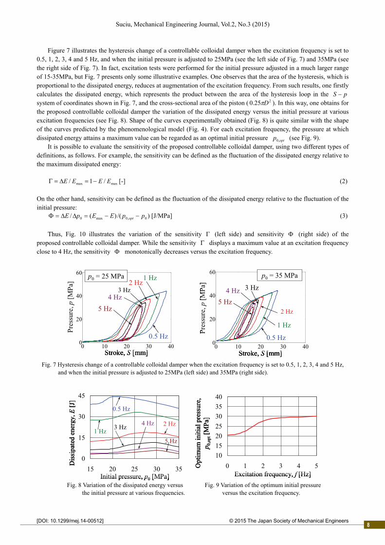
Figure 7 illustrates the hysteresis change of a controllable colloidal damper when the excitation frequency is set to 0.5, 1, 2, 3, 4 and 5 Hz, and when the initial pressure is adjusted to 25MPa (see the left side of Fig. 7) and 35MPa (see the right side of Fig. 7). In fact, excitation tests were performed for the initial pressure adjusted in a much larger range of 15-35MPa, but Fig. 7 presents only some illustrative examples. One observes that the area of the hysteresis, which is proportional to the dissipated energy, reduces at augmentation of the excitation frequency. From such results, one firstly calculates the dissipated energy, which represents the product between the area of the hysteresis loop in the pS system of coordinates shown in Fig. 7, and the cross-sectional area of the piston ( 225.0 D ). In this way, one obtains for the proposed controllable colloidal damper the variation of the dissipated energy versus the initial pressure at various excitation frequencies (see Fig. 8). Shape of the curves experimentally obtained (Fig. 8) is quite similar with the shape of the curves predicted by the phenomenological model (Fig. 4). For each excitation frequency, the pressure at which dissipated energy attains a maximum value can be regarded as an optimal initial pressure optp ,0 (see Fig. 9).
It is possible to evaluate the sensitivity of the proposed controllable colloidal damper, using two different types of definitions, as follows. For example, the sensitivity can be defined as the fluctuation of the dissipated energy relative to the maximum dissipated energy:
maxmax /1/ EEEE [-] (2)
On the other hand, sensitivity can be defined as the fluctuation of the dissipated energy relative to the fluctuation of the initial pressure:
)/()(/ 0,0max0 ppEEpE opt [J/MPa] (3)
Thus, Fig. 10 illustrates the variation of the sensitivity (left side) and sensitivity (right side) of the
proposed controllable colloidal damper. While the sensitivity displays a maximum value at an excitation frequency close to 4 Hz, the sensitivity monotonically decreases versus the excitation frequency.
Fig. 7 Hysteresis change of a controllable colloidal damper when the excitation frequency is set to 0.5, 1, 2, 3, 4 and 5 Hz, and when the initial pressure is adjusted to 25MPa (left side) and 35MPa (right side).
Fig. 8 Variation of the dissipated energy versus Fig. 9 Variation of the optimum initial pressure the initial pressure at various frequencies. versus the excitation frequency.
0 10 20 30 400
20
40
60 p0 = 35 MPa
2 Hz
3 Hz
0.5 Hz
1 Hz
4 Hz
5 Hz
Stroke, S [mm]
Pre
ssur
e, p
[MP
a]
0 10 20 30 400
20
40
60 p0 = 25 MPa2 Hz
3 Hz
0.5 Hz
1 Hz
4 Hz
5 Hz
Stroke, S [mm]
Pre
ssur
e, p
[MP
a]
0 10 20 30 400
20
40
60 p0 = 35 MPa
2 Hz
3 Hz
0.5 Hz
1 Hz
4 Hz
5 Hz
Stroke, S [mm]
Pre
ssur
e, p
[MP
a]
0 10 20 30 400
20
40
60 p0 = 35 MPa
2 Hz
3 Hz
0.5 Hz
1 Hz
4 Hz
5 Hz
Stroke, S [mm]
Pre
ssur
e, p
[MP
a]
0 10 20 30 400
20
40
60 p0 = 25 MPa2 Hz
3 Hz
0.5 Hz
1 Hz
4 Hz
5 Hz
Stroke, S [mm]
Pre
ssur
e, p
[MP
a]
0 10 20 30 400
20
40
60 p0 = 25 MPa2 Hz
3 Hz
0.5 Hz
1 Hz
4 Hz
5 Hz
Stroke, S [mm]
Pre
ssur
e, p
[MP
a]
0
15
30
45
15 20 25 30 35Initial pressure, p0 [MPa]
Dis
sipa
ted
ener
gy, E
[J]
0.5 Hz
1 Hz2 Hz3 Hz
4 Hz
5 Hz
10
15
20
25
30
35
40
0 1 2 3 4 5Excitation frequency, f [Hz]
Opt
imum
initi
al p
ress
ure,
p 0
,opt
[MP
a]
0
15
30
45
15 20 25 30 35Initial pressure, p0 [MPa]
Dis
sipa
ted
ener
gy, E
[J]
0.5 Hz
1 Hz2 Hz3 Hz
4 Hz
5 Hz
0
15
30
45
15 20 25 30 35Initial pressure, p0 [MPa]
Dis
sipa
ted
ener
gy, E
[J]
0.5 Hz
1 Hz2 Hz3 Hz
4 Hz
5 Hz
10
15
20
25
30
35
40
0 1 2 3 4 5Excitation frequency, f [Hz]
Opt
imum
initi
al p
ress
ure,
p 0
,opt
[MP
a]
10
15
20
25
30
35
40
0 1 2 3 4 5Excitation frequency, f [Hz]
Opt
imum
initi
al p
ress
ure,
p 0
,opt
[MP
a]
8

2
Suciu, Mechanical Engineering Journal, Vol.2, No.3 (2015)
© 2015 The Japan Society of Mechanical Engineers[DOI: 10.1299/mej.14-00512]
Fig. 10 Variation of the sensitivity (left side) and sensitivity (right side) of the proposed controllable damper.
Next, damping coefficient can be calculated from the results presented in Fig. 8 for the dissipated energy, by using
the relationships given at Nomenclature, Eq. (1) and Table 3. In this way, one obtains for the proposed controllable colloidal damper the variation of the damping coefficient versus the initial pressure at various excitation frequencies (see the left side of Fig. 11) and also, the variation of the damping coefficient versus the excitation frequency at various initial pressures (see the right side of Fig. 11). Shape of the curves obtained experimentally (see the left side of Fig. 11) is quite similar with the shape of the curves predicted by the phenomenological model (see Fig. 5). Since the damping coefficient considerably changes as the initial pressure is adjusted, one concludes that the damping characteristics of the proposed colloidal damper can be effectively controlled with respect to the adjustment of the initial pressure.
In order to fully understand the shape of curves shown in Fig. 11, it is important to stress that, as the excitation frequency f becomes higher, the amplitude VS of the displacement excitation becomes lower. This fact is well confirmed by the analysis of various types of rough roads surfaces. Since at augmentation of the excitation frequency, the hysteresis becomes smaller (see Fig. 7), the dissipated energy reduces (see Fig. 8), and consequently, the damping coefficient decreases as clearly illustrated by Fig. 11.
Fig. 11 Variation of the damping coefficient versus the initial pressure at various excitation frequencies (left side) and variation of the damping coefficient versus the excitation frequency at various initial pressures (right side).
For any value of the piston stroke ],0[ maxSS the spring constant )(SKK can be determined as the slope dSdF / of the graph illustrating the variation of the mean force versus the stroke (see the right side of Fig. 12). Such
mean force can be determined by multiplying the mean pressure )(Spp mm (see the red curves on the left side of Fig. 12, or the green lines on Fig. 3) by the piston cross-sectional area ( 225.0 D ). Then, the mean spring constant is calculated as:
max
0
1max )(
S
dSSKSK (4)
In this way, one obtains the variation of the spring constant for the proposed controllable colloidal damper versus
0
0.2
0.4
0.6
0.8
1
0 1 2 3 4 5
0
0.2
0.4
0.6
0.8
1
0 1 2 3 4 5
Sen
sitiv
ity,
[J
/MP
a]
Excitation frequency, f [Hz] Excitation frequency, f [Hz]
Sen
sitiv
ity,
[-
]
0
0.2
0.4
0.6
0.8
1
0 1 2 3 4 5
0
0.2
0.4
0.6
0.8
1
0 1 2 3 4 5
Sen
sitiv
ity,
[J
/MP
a]
Excitation frequency, f [Hz] Excitation frequency, f [Hz]
Sen
sitiv
ity,
[-
]
15 20 25 30 35
Dam
ping
coe
ffic
ient
, C
[Ns/
mm
]
0.5 Hz
1 Hz2 Hz
3 Hz4 Hz
5 Hz0
4
8
12
16
20
Initial pressure, p0 [MPa]0 1 2 3 4 5
15 MPa
25 MPa30 MPa
20 MPa
35 MPa
0
4
8
12
16
20
Dam
ping
coe
ffic
ient
, C
[Ns/
mm
]
Excitation frequency, f [Hz]15 20 25 30 35
Dam
ping
coe
ffic
ient
, C
[Ns/
mm
]
0.5 Hz
1 Hz2 Hz
3 Hz4 Hz
5 Hz0
4
8
12
16
20
Initial pressure, p0 [MPa]15 20 25 30 35
Dam
ping
coe
ffic
ient
, C
[Ns/
mm
]
0.5 Hz
1 Hz2 Hz
3 Hz4 Hz
5 Hz0
4
8
12
16
20
Initial pressure, p0 [MPa]0 1 2 3 4 5
15 MPa
25 MPa30 MPa
20 MPa
35 MPa
0
4
8
12
16
20
Dam
ping
coe
ffic
ient
, C
[Ns/
mm
]
Excitation frequency, f [Hz]0 1 2 3 4 5
15 MPa
25 MPa30 MPa
20 MPa
35 MPa
0
4
8
12
16
20
Dam
ping
coe
ffic
ient
, C
[Ns/
mm
]
Excitation frequency, f [Hz]
9
2
Suciu, Mechanical Engineering Journal, Vol.2, No.3 (2015)
© 2015 The Japan Society of Mechanical Engineers[DOI: 10.1299/mej.14-00512]
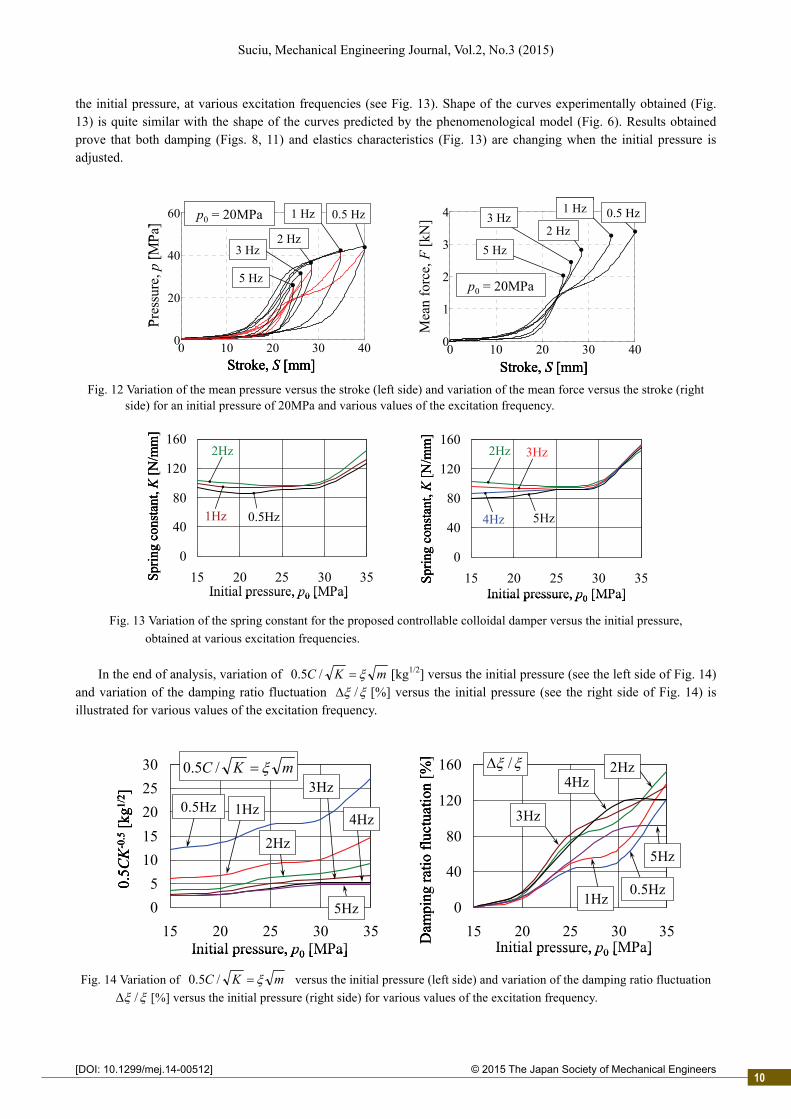
the initial pressure, at various excitation frequencies (see Fig. 13). Shape of the curves experimentally obtained (Fig. 13) is quite similar with the shape of the curves predicted by the phenomenological model (Fig. 6). Results obtained prove that both damping (Figs. 8, 11) and elastics characteristics (Fig. 13) are changing when the initial pressure is adjusted.
Fig. 12 Variation of the mean pressure versus the stroke (left side) and variation of the mean force versus the stroke (right side) for an initial pressure of 20MPa and various values of the excitation frequency.
Fig. 13 Variation of the spring constant for the proposed controllable colloidal damper versus the initial pressure,
obtained at various excitation frequencies. In the end of analysis, variation of mKC /5.0 [kg1/2] versus the initial pressure (see the left side of Fig. 14)
and variation of the damping ratio fluctuation / [%] versus the initial pressure (see the right side of Fig. 14) is illustrated for various values of the excitation frequency.
Fig. 14 Variation of mKC /5.0 versus the initial pressure (left side) and variation of the damping ratio fluctuation
/ [%] versus the initial pressure (right side) for various values of the excitation frequency.
0
40
80
120
160
15 20 25 30 35Spr
ing
cons
tant
, K[N
/mm
]
2Hz 3Hz
5Hz4Hz
Initial pressure, p0 [MPa]
0
40
80
120
160
15 20 25 30 35
1Hz
Initial pressure, p0 [MPa]
2Hz
0.5Hz
Spri
ng c
onst
ant,
K[N
/mm
]
0
40
80
120
160
15 20 25 30 35Spr
ing
cons
tant
, K[N
/mm
]
2Hz 3Hz
5Hz4Hz
Initial pressure, p0 [MPa]
0
40
80
120
160
15 20 25 30 35Spr
ing
cons
tant
, K[N
/mm
]
2Hz 3Hz
5Hz4Hz
Initial pressure, p0 [MPa]
0
40
80
120
160
15 20 25 30 35
1Hz
Initial pressure, p0 [MPa]
2Hz
0.5Hz
Spri
ng c
onst
ant,
K[N
/mm
]
0
40
80
120
160
15 20 25 30 35
1Hz
Initial pressure, p0 [MPa]
2Hz
0.5Hz
Spri
ng c
onst
ant,
K[N
/mm
]
0 10 20 30 400
20
40
60
Pre
ssur
e, p
[MP
a]
Stroke, S [mm]
0.5 Hz1 Hz
2 Hz3 Hz
5 Hz
p0 = 20MPa
0 10 20 30 400
1
2
3
4
Mea
n fo
rce,
F[k
N]
Stroke, S [mm]
p0 = 20MPa
0.5 Hz1 Hz
5 Hz
3 Hz2 Hz
0 10 20 30 400
20
40
60
Pre
ssur
e, p
[MP
a]
Stroke, S [mm]
0.5 Hz1 Hz
2 Hz3 Hz
5 Hz
p0 = 20MPa
0 10 20 30 400
20
40
60
Pre
ssur
e, p
[MP
a]
Stroke, S [mm]
0.5 Hz1 Hz
2 Hz3 Hz
5 Hz
p0 = 20MPa
0 10 20 30 400
1
2
3
4
Mea
n fo
rce,
F[k
N]
Stroke, S [mm]
p0 = 20MPa
0.5 Hz1 Hz
5 Hz
3 Hz2 Hz
0 10 20 30 400
1
2
3
4
Mea
n fo
rce,
F[k
N]
Stroke, S [mm]
p0 = 20MPa
0.5 Hz1 Hz
5 Hz
3 Hz2 Hz
0
5
10
15
20
25
30
15 20 25 30 35Initial pressure, p0 [MPa]
0.5Hz
0.5C
K-0
.5[k
g1/2 ]
1Hz
2Hz
3Hz
4Hz
5Hz
mKC /5.0
0
40
80
120
160
15 20 25 30 35Dam
ping
rat
io f
luct
uatio
n [%
]
Initial pressure, p0 [MPa]
0.5Hz1Hz
/ 2Hz4Hz
5Hz
3Hz
0
5
10
15
20
25
30
15 20 25 30 35Initial pressure, p0 [MPa]
0.5Hz
0.5C
K-0
.5[k
g1/2 ]
1Hz
2Hz
3Hz
4Hz
5Hz
mKC /5.0
0
5
10
15
20
25
30
15 20 25 30 35Initial pressure, p0 [MPa]
0.5Hz
0.5C
K-0
.5[k
g1/2 ]
1Hz
2Hz
3Hz
4Hz
5Hz
mKC /5.0
0
40
80
120
160
15 20 25 30 35Dam
ping
rat
io f
luct
uatio
n [%
]
Initial pressure, p0 [MPa]
0.5Hz1Hz
/ 2Hz4Hz
5Hz
3Hz
0
40
80
120
160
15 20 25 30 35Dam
ping
rat
io f
luct
uatio
n [%
]
Initial pressure, p0 [MPa]
0.5Hz1Hz
/ 2Hz4Hz
5Hz
3Hz
10

2
Suciu, Mechanical Engineering Journal, Vol.2, No.3 (2015)
© 2015 The Japan Society of Mechanical Engineers[DOI: 10.1299/mej.14-00512]
Since the damping and elastic characteristics of the proposed colloidal damper are not depending on the selected value of the sprung mass ( m ), in the left side of Fig. 14 the ordinate m is preferred instead the damping ratio. In this way, the generalized results presented in the left side of Fig. 14 can be then particularized for a specific value of the sprung mass. One observes that, although the spring constant is also changing against the initial pressure, shape of the curves shown in the left side of Fig. 14 is similar with the shape of the graphs illustrated for the damping coefficient in the left side of Fig. 11. Since the damping ratio largely fluctuates versus the initial pressure, Fig. 14 confirms that an efficient controllable colloidal damper can be achieved by taking the initial pressure as parameter of control. On the other hand, since the obtained damping ratio fluctuation (up to 153%), is larger than the required change of damping ratio for a Kelvin-Voigt suspension (133%, see Section 4.1) and also is larger than the required change of damping ratio for a Maxwell suspension (100%, see Section 4.2), one concludes that the proposed controllable colloidal damper has the ability to accommodate real applications. 7. Conclusions and future work
The following conclusions were inferred from the phenomenological and experimental investigation performed: 1) Even a colloidal damper has large damping ability, when subjected to the displacement excitation without
dynamic pressurization, if the amplitude of the displacement excitation is smaller than the maximum stroke, only a small part of the vibration energy will be dissipated. However, considering the initial pressure or the corresponding start position as a controllable parameter, under dynamic pressurization, the displacement excitation occurs as displaced over a certain distance and a large part of the vibration energy will be dissipated if the initial pressure is set to appropriate moderate values. A change in the dissipated energy is accompanied by a change in the damping coefficient and also by a change in the spring constant. Thus, by applying a dynamic pressurization, the dissipative and elastic properties of the colloidal damper can be adjusted.
2) While the damping coefficient of the proposed controllable colloidal damper monotonically increases at augmentation of the dynamic pressurization, the dissipated energy attains a maximum and the spring constant reaches a minimum at a certain value of the initial pressure. Although the spring constant is also changing against the initial pressure, shape of the curves illustrating the variation of the generalized damping ratio versus the initial pressure is similar with the shape of the graphs illustrating the variation of the damping coefficient versus the initial pressure.
3) Since the experimentally obtained damping ratio fluctuation (up to 153%), is larger than the required change of damping ratio for Kelvin-Voigt and Maxwell suspensions (133% and 100%, respectively), one concludes that the proposed controllable colloidal damper has the ability to accommodate real applications.
In the end, some unsolved problems and possible future works on the subject of controllable colloidal dampers can be suggested as follows:
A) Strongly non-linear effects of the suspension system were observed in this work, for the commercially available porous silicas. Damping coefficients and the equivalent spring constants, calculated in these circumstances, were forcibly correlated with the required change of damping ratio for a controllable suspension. Corrections for the strong non-linear effects and redesign of the silica particles to eventually achieve linear colloidal suspension will be addressed in the future work.
B) Although the vibration caused by the road roughness is unknown broadband vibration, in this work one considered only the response to sinusoidal vibration under the assumption that the amplitude and frequency are known and independently varied. However, the control method should be improved to prove its usefulness for a real road of random roughness.
C) Comparison of the characteristics of the semi-active colloidal damper with those provided by other types of semi-active dampers should be addressed in the future work, in order to emphasize the advantages and disadvantages of the proposed controllable colloidal suspension.
References Suciu, C.V. and Tobiishi, T., Comfortableness evaluation of an autovehicle equipped with colloidal suspensions,
Journal of System Design and Dynamics, Vol. 6, No. 5 (2012), pp. 555–567. Suciu, C.V. and Buma, S., On the structural simplification, compact and light design of a vehicle suspension, achieved
11

2
Suciu, Mechanical Engineering Journal, Vol.2, No.3 (2015)
© 2015 The Japan Society of Mechanical Engineers[DOI: 10.1299/mej.14-00512]
by using a colloidal cylinder with a dual function of absorber and compression-spring, Proceedings of the FISITA World Automotive Congress, Vol. 10 (2012), pp. 21–32.
Suciu, C.V., Actively controlled colloidal damper, Japanese patent disclosure 2008/001356 (2008, in Japanese) and US patent disclosure 2010/0193305 A1 (2010a).
Suciu, C.V., Investigations on a smart nano- energy absorption system, Trans Tech Publications, Advanced Materials Research, Vols. 123-125 (2010b), pp. 987–990.
Suciu, C.V., Fujimoto, T., Fukamatsu F. and Yamauchi, S., Experimental study on an active control colloidal damper for car suspension, Proceedings of the Dynamics and Design Conference, CD-ROM (2009), pp. 1–6 (in Japanese).
Suciu, C.V., Araki, Y. and Tobiishi, T., Investigation of the damping and elastic characteristics of an active control colloidal damper, Proceedings of the Mechanical Engineering Congress (2010), pp. 183–184 (in Japanese).
Suciu, C.V. and Yaguchi K., Endurance Tests on a Colloidal Damper Destined to Vehicle Suspension, Experimental Mechanics, Vol. 49 (2009), pp. 383–393.
Suciu, C.V., Tobiishi, T. and Mouri, R., Modeling and simulation of a vehicle suspension with variable damping versus the excitation frequency, Journal of Telecommunications and Information Technology, No. 1/2012 (2012), pp. 83–89.
12