experimental investigation of unsteady flow field - personal psu
TRANSCRIPT

Proceedings of ASME Turbo Expo 2002 June 3-6, 2002, Amsterdam, The Netherlands
EXPERIMENTAL INVESTIGATION OF UNSTEADY FLOW FIELD WITHIN A TWO STAGE AXIAL TURBOMACHINE USING PARTICLE IMAGE VELOCIMETRY
Oguz Uzol, Yi-Chih Chow, Joseph Katz, Charles Meneveau
Department of Mechanical Engineering Johns Hopkins University
Baltimore, MD 21218
Proceedings of ASME TURBO EXPO 2002
June 3-6, 2002, Amsterdam, The Netherlands
GT-2002-30664
ABSTRACT Detailed measurements of the flow field within the entire 2nd
stage of a two stage axial turbomachine are performed using Particle Image Velocimetry. The experiments are performed in a facility that allows unobstructed view on the entire flow field, facilitated using transparent rotor and stator and a fluid that has the same optical index of refraction as the blades. The entire flow field is composed of a “lattice of wakes”, and the resulting wake-wake and wake-blade interactions cause major flow and turbulence non-uniformities. The paper presents data on the phase averaged velocity and turbulent kinetic energy distributions, as well as the average-passage velocity and deterministic stresses. The phase-dependent turbulence parameters are determined from the difference between instantaneous and the phase-averaged data. The distributions of average-passage flow field over the entire stage in both the stator and rotor frames of reference are calculated by averaging the phase-averaged data. The deterministic stresses are calculated from the difference between the phase-averaged and average-passage velocity distributions. Clearly, wake-wake and wake-blade interactions are the dominant contributors to generation of high deterministic stresses and tangential non-uniformities, in the rotor-stator gap, near the blades and in the wakes behind them. The turbulent kinetic energy levels are generally higher than the deterministic kinetic energy levels, whereas the shear stress levels are comparable, both in the rotor and stator frames of references. At certain locations the deterministic shear stresses are substantially higher than the turbulent shear stresses, such as close to the stator blade in the rotor frame of reference. The non-uniformities in the lateral velocity component due to the interaction of the rotor blade with the 1st stage rotor-stator wakes, result in 13% variations in the specific work input of the rotor. Thus, in spite of the relatively large blade row spacings in the present turbomachine, the non-uniformities in flow structure have significant effects on the overall performance of the system.
1 1
NOMENCLATURE k Turbulent kinetic energy kdet Deterministic kinetic energy Ls Stage length starting from the rotor leading edge N Total number of instantaneous samples NaI Sodium Iodide t Time T Blade passing period u Instantaneous axial velocity Utip Velocity of rotor blade tip v Instantaneous lateral velocity
V Velocity magnitude
vu ′′− Reynolds shear stress W* Specific Work Input Variation x Axial direction. x=0 is the rotor leading edge y Lateral direction (almost circumferential but the laser sheet is flat) Greek symbols α Phase averaged flow angle (yaw angle) φ Rotor Phase
detijτ Deterministic shear stress tensor
Superscripts R Rotor frame of reference S Stator frame of reference Subscripts 1 not including the upstream non-uniformity 2 including the upstream non-uniformity av tangential average d downstream u upstream Overbars − Phase averaged value ∧ Average –passage value
Copyright © 2002 by ASME

INTRODUCTION The unsteadiness in a multi-stage turbomachine is generally
described in two parts: The “non-deterministic” (random) unsteadiness, referring to the fluctuations due to turbulence, associated, for example with blade wakes, and “deterministic” (periodic) unsteadiness, referring to fluctuations in the flow field correlated with the shaft frequency (or blade-rate frequency). The overall aerodynamics, vibration and acoustic characteristics of the machine are significantly affected by both forms of unsteadiness.
In the numerical simulations of turbomachinery, unsteady RANS equations have to be solved in order to determine the time (phase) dependent characteristics of the flow field. This approach is still impractical as a design tool for turbomachines with multiple blade rows and varying number of rotor and stator blades. Instead, an “averaged” flow state can be determined by solving the “average-passage” RANS equations, introduced first by Adamczyk [1]. This approach accounts for the effects of the phase-dependent unsteadiness and spatial non-uniformities associated with neighboring blade rows but does not resolve them. Three different averaging operators are being employed, the first being “ensemble averaging,” that account for the turbulence and is used also in unsteady RANS. The second operator is “time averaging” that removes the deterministic unsteady flow, covering time scales that are of the order of the shaft period, including the phase-dependent variations in flow structure. The third operator is “passage to passage averaging”, necessary for turbomachinery with varying number of rotors and stators on consecutive stages. When these operators are applied to the Navier-Stokes equations one obtains the average-passage RANS equations. In this formulation each blade row has a steady average-passage flow field, and neighboring blade rows are coupled (replaced with) through circumferencially uniform systems of body forces, energy sources and deterministic stresses (Adamczyk [1], Adamczyk et al. [2], Adamczyk et al. [3], Rhie et al. [4], LeJambre et al.[5], Busby et al.[6]). The effects of phase-dependent unsteadiness on the average-passage flow field are accounted for through the “deterministic stresses”. These stresses must be modeled in order to obtain a closed system of equations. The mixing plane approach is another simpler method for transferring the information between blade rows using boundary conditions in a plane located between the rows (e.g., Dawes [7], Denton [8]).
Previous studies have reported that deterministic stresses can be of similar or higher magnitude than the Reynolds stresses (Rhie et al. [4], Lejambre et al. [5], Sinha et al. [16]). Therefore neglecting these interactions may lead to significant errors. Different models for the deterministic stresses have already been proposed (e.g. Adamczyk [2], Van de Wall [9], Meneveau and Katz, [10]), but unlike RANS closure models, there are no widely accepted and validated modeling tools. To develop these models one requires a data-base obtained either from experiments or unsteady RANS involving multistages, the latter introducing uncertainties related to turbulence closure models. In previous experimental studies, the deterministic stresses have been obtained from single point measurements (hot-wire, hot-film, split hot-film, five hole probe, etc.) and by traversing in between the
2 2
blade rows and within blade passages (e.g. Prato et al. [11][12], Suryavamshi et al. [13][14]). Recent papers by Sinha and Katz [15] and Sinha et al. [16] provide deterministic stress distributions in a centrifugal pump obtained using 2D PIV. The present paper provides detailed data on the distributions of deterministic stresses in a multi-stage axial turbomachine.
In order to understand the physical mechanisms and cause and effect relations of the unsteadiness, which lead to improved deterministic stress models, experimental data over the entire flow fields in a multi-stage turbomachine is essential. The axial turbomachinery facility introduced by Uzol et al [17] and Chow et al [18] [21] enables us to perform 2D PIV measurements covering an entire stage of a turbomachine, from the rotor inlet to the stator exit. This facility uses transparent rotor and stator blades operating in a solution of NaI, which has the same optical index of refraction as the blades, hence allowing optical access to the entire flow field. Detailed PIV measurements performed in this facility provide the data base for detailed phase-averaged and average-passage velocity distributions, along with the deterministic stresses and turbulence parameters. These measurements cover the entire 2nd stage of a two-stage turbomachine, from the inlet to the rotor to the exit from stator. The present data-base is composed of measurements performed at 500 rpm, at mid span, close to design conditions and at ten different rotor phases relative to the stator blade (every 3°), covering an entire rotor passage. The ten phase-averaged flow fields, obtained (each) by averaging 100 instantaneous distributions, are used to calculate the average-passage flow fields both in the stator and rotor frames of references. The deterministic stresses are determined from the difference between the phase averaged and average-passage velocity distributions. The causes for the deterministic stresses are identified and compared to the distributions of Reynolds stresses. Finally, the causes of non-uniformities in the average-passage flow field and their impact on the performance of the rotor blade row are presented and discussed.
EXPERIMENTAL SETUP AND PROCEDURES Facility
The axial turbomachine test facility enables us to perform detailed and complete PIV measurements at any point within an entire stage including the rotor, stator, gap between them, inflow into the rotor and the wake structure downstream of the stator. To generate such data using optical techniques one needs unobstructed view of the entire domain at any phase angle. This unlimited optical access is facilitated using a rotor and stator made of a transparent material (acrylic) that has the same optical index of refraction as the working fluid, a concentrated solution, 62%-64% by weight, of NaI in water. This fluid has a specific gravity of 1.8 and a kinematic viscosity of 1.1x10⁻⁶ m2/s (i.e. very close to that of water). Thus, the blades become almost invisible, do not obstruct the field of view and do not alter the direction of the illuminating laser sheet required for PIV measurements. Information related to use and maintenance of the NaI solution can be found in Uzol et al. [17].
Copyright © 2002 by ASME

The two-stage axial turbomachine shown in Figure 1 has four blade rows. There are 12 rotor blades, each with a chordlength of 50 mm, span of 44.5 mm, thickness of 7.62 mm and camber varying from 2.54 mm at the hub to 1.98 mm at the tip. The resulting Reynolds number based on the tip speed and rotor chordlength is 3.7x10⁵ at 500 rpm, the speed of the present tests. The stators have 17 blades, each with a chordlength of 73.2 mm, span of 44.5 mm, thickness of 11 mm and camber of 6.22 mm. The system is driven by a 25 HP rim-driven motor, preventing the need for a long shaft, and the two rotors are connected by a common shaft, supported by precision bearings. More details about the facility can be found in Chow et al. [18] and the main geometrical parameters are listed in Table 1.
Figure 1. Test section of the axial turbomachine. The 2nd stage rotors and stators are made of transparent acrylic.
Table 1. The geometrical parameters for the axial turbomachine used in the present experiments. R2 and S2 refer to the 2nd stage rotor and stator, respectively. S1 is the 1st stage stator
No. of stages 2 R2-S2 axial gap / Rotor axial chord (mid-span)
1.92
No. of rotor blades 12 S1-R2 axial gap / Rotor axial chord (mid-span)
1.95
No. of stator blades 17 Rotor pitch-to-chord ratio (mid-span)
1.34
Hub-to-tip ratio 0.708 Stator pitch-to-chord ratio (mid-span)
0.66
PIV Setup and Experimental Procedure
The measurements cover the entire 2nd stage. Data has been obtained at 10 rotor phases, every three degrees of blade orientation, covering an entire rotor blade passage of 30°. In this paper we present data for the mid-span plane and at 500 rpm. At least one hundred instantaneous realizations are recorded for each phase and location. For selected cases we record 1000 images in order to obtain converged statistics on the turbulence. The sample area is 50x50 mm2, and as a result several data sets at different axial locations have been collected to cover the entire stage. Data analysis including image enhancement and cross-correlation analysis is performed using in-house developed software and
3 3
procedures (Roth et al. [19][20]). Adapting these procedures to the current geometry, including modifications to the image enhancement procedures, and removal of the blade trace/signature prior to velocity computations are discussed in Uzol et al. [17]. Additional details about the PIV setup, data acquisition system and uncertainty estimates can be found in Chow et al. [21].
RESULTS AND DISCUSSION Phase averaged flow fields
Using the instantaneous measurements, the phase averaged results are calculated using,
∑=
φ=φN
1ii ),x,y(u
N
1)y,(xu , ∑
=φ=φ
N
1ii ),x,y(v
N
1)y,(xv , (1)
( ) ( )[ ]∑=
φ−φ+φ−φ=φN
1i
22 y,(xv)y,x(v)y,(xu)y,x(uN
1
4
3)y,k(x, ),,,, ii
(2)
[ ][ ]∑=
φ−φφ−φ−=φ′′−N
1ii y,(xv)y,x(v)y,(xu)y,x(u
N
1),y,x(vu ),,,,i
(3)
φφ=φα −
),y,x(u),y,x(v
tan),y,x( 1 (4)
where N=100 is the number of instantaneous vector maps for each phase, u and v are the mean streamwise and lateral (almost circumferential, although the light sheet is flat) velocity components, respectively, and φ is the phase angle. The 3/4 coefficient of k, the “turbulent kinetic energy”, is selected to account for the variance of the out of plane velocity component assuming that it is an average of the available measured components.
Figure 2 shows the phase averaged velocity and turbulent kinetic energy distributions for two different rotor phases. The high momentum regions on the suction side of the stator blade, along the aft suction side the rotor blade, and in the rotor wake are clearly visible. One can observe the phase dependent variations of the velocity field, for example on the suction side of the stator blade. At t/TR=0.0 (TR is the rotor blade-passage period) a rotor wake, easily identified in the k distribution, is impinging on the stator blade and the high momentum region on the suction side is split into two separate zones (Figure 2). Conversely, at t/TR =0.6 the rotor wake is not impinging on the stator, and there is only a single high momentum zone on the blade. At this phase one rotor wake is located just upstream of the stator and a second (the one located near the leading edge at t/TR=0.0) impinges on the blade at mid chord, downstream of the high momentum region.
The distributions of turbulent kinetic energy clearly demonstrate that the flow field consists of a lattice of wakes formed both by the blades of the 1st stage, located upstream of the sample area, and by visible blades of the 2nd stage. As the almost horizontally aligned 1st stage wakes pass through the 2nd stage rotor they are chopped off, creating wake segments. An example of such a 1st stage stator wake segment is evident in the k distribution t/TR=0.0, between the rotor blade and the wake of a previous blade (x/LS=0.25, y/LS=0.1). The 1st stage stator
Copyright © 2002 by ASME

wake trajectory becomes discontinuous across the rotor wake (and blade) because of the differences in the velocity magnitude on the suction and pressure sides of the rotor blade. An example of stator wake “shearing” can be seen in the turbulent kinetic energy plot at t/TR=0.6. A little less obvious but still evident is the inclined wake of the 1st stage rotor, which is located 6.5 rotor axial chords upstream. At t/TR =0.0, it engulfs the leading edge of the 2nd stage rotor blade, and at t/TR =0.6 it is located above the emerging blade leading edge.
The 2nd stage stator blade chops off the incoming rotor wakes, and the resulting train of inclined wake segments is transported through the stator passage. At t/TR=0.0 (Figure 2) one can identify two rotor wakes inside the stator passage, a third segment is located at the exit from the passage and another one is approaching the leading edge of the stator blade. The latter is being chopped by the leading edge of the stator at t/TR=0.6. The interaction of these wake segments with the stator wake causes phase dependent oscillations of the stator wake trajectory, to a great part due to variations in flow angle within the rotor wake segment (Chow et al. [18]). The extent of the high turbulent kinetic energy zone in the core of the stator wake also expands and contracts depending on the location of the intersection with the rotor wake segment. More information can be found in Chow et al [18], [21].
Inherently, the flow field in the rotor frame of reference is also phase dependent. Unfortunately, the field of view of the current experiments (50x50 mm2, height of Figure 2) does not allow us to obtain the entire flow field around a rotor blade from a single phase measurement. For each rotor phase, we can either see the flow around the leading edge or the wake region of the blade. Nevertheless, it is possible to construct the entire flow field by matching corresponding data sets obtained in different phases - rotor orientations relative to the stator. This phase matching procedure can be explained as follows:
To begin, we recall that the experiments are performed in the stator frame of reference. For 12 rotor blades, the rotor blade passage of 30° is covered by collecting 10 independent data sets every 3° of blade orientation. Hence, assuming rotor passage-to-passage periodicity, the phase that follows phase 10 (t/TR =0.9) would be the same as phase 1 (t/TR=0.0). In the rotor frame of reference, the stator passage is covered in 21.2° of rotation since there are 17 stator blades. Therefore, a specific rotor blade is located in almost the same position with respect to the stator every 7th phase of our data sets. For example, the rotor blade in phase 3 (middle set in Figure 3) is located in phase 10 at almost the same position (0.2° difference) with respect to the following stator blade, but in phase 10 (bottom set of figure 3) that particular rotor blade and the stator blade that it is facing are out of our field of view. Thus, phases 3 and 10 represent matched conditions of rotor orientation relative to the stator, and in fact, phase 10 shows the wake of the blade in phase 3. Similarly, phase 6 can be positioned on top of phase 3 since it represents matched conditions that have occurred 21° of blade orientation before phase 3. This matching procedure allows us to reconstruct the entire flow field in the rotor
4 4
blade row (Figure 3). Of course, the inherent assumption of this procedure is that the flow field in rotor passages is periodic. Since the sample phases presented in Figure 3 are recorded independently, and the mean flow and turbulence structures/features seem to be continuous across the matched sets, the assumption of rotor passage-to-passage periodicity seems to be valid for this turbomachine. The complex flow field with the lattice structure formed by the 1st and 2nd stage rotor and stator wakes become more evident in Figure 3.
Matching all the appropriate rotor phases relative to the stator enables us to construct the entire flow field around the rotor blade in the rotor frame of reference, including its inlet and its wake. Figure 4a, b and c are the resulting sample distributions of phase-averaged velocity, phase-averaged flow angle and turbulent kinetic energy, respectively, around the rotor blade at 2 different stator phases. As expected, the flow field in the rotor frame of reference is also dominated by the interaction with the 1st stage stator and rotor wakes. In phase t/TS=0.286 (Ts is the stator passage period) a stator wake, characterized by high k and low α , is just starting to impinge on the rotor blade. The inclined region with elevated turbulent kinetic energy just above this stator wake is the 1st stage rotor wake. Another sheared/segmented wake can be identified, one part on the pressure side of the blade and the other near the trailing edge on the suction side. As noted before, the discontinuity in wake trajectory is caused by the differences in velocities on the suction and pressure sides of the blade. In the rotor frame of reference the wake segment on the suction side moves downward faster than the segment on the pressure side. At t/TS=0.858, the stator wakes are translated downward, and the stator wake located in the previous set near the leading edge is now chopped off, as it moves at different speeds on both sides of the blade. At t/TS=0.858, the rotor blade is also starting to cut through the 1st stage rotor wake.
The flow non-uniformities associated with wake-blade and wake-wake interactions are discussed in detail in Chow et al [21]. However, a few examples that have bearings on the present paper should be mentioned. For example, the phase averaged velocity contours t/TS=0.286 show that there is a low momentum zone accompanied by (mostly) high (negative) flow angle on the pressure side of the rotor blade. This region coincides with the intersection of the 1st stage stator and rotor wakes. At t/TS=0.858 the same wake intersection and associated non-uniformities can be seen interacting with the rotor wake, just downstream of the rotor trailing edge (at about 0.1<x/LS<0.2, 0.1<y/LS<0.2).
The interaction of the stator wake segments with the 2nd stage rotor wakes cause phase-dependent meandering of the rotor wake, evident for example, in the upper rotor wake at t/TS=0.286 (Figure 4). The wake intersections also involve substantial increase in the magnitude of flow angle towards axial flow in the absolute frame of reference. As demonstrated in Chow et al [21], the rotor wake is sheared by the non-uniformities in the horizontal velocity distributions (absolute frame), which are a direct result of the “discontinuities” in the
Copyright © 2002 by ASME

t/TR = 0.0
t/TR=0.6
Figure 2. Phase averaged velocity in the stator frame of reference ( SV ) and Turbulent kinetic energy (k) at 2 rotor phases covering
the entire 2nd stage. Utip = 8 m/s is the blade tip velocity at 500 rpm, LS = 203 mm is the stage length and x=0 is the rotor leading edge. Arrow shows the rotor direction.
Figure 3. Matched sets of phase averaged absolute velocity ( SV ) and turbulent kinetic energy (k) consisting of, from bottom to top,
phase 10 (t/TR=0.9), phase 3 (t/TR=0.2) and phase 6 (t/TR=0.5). Arrow shows the rotor direction.
Phase 6
Phase 3
Phase 10
SV / Utip k / U2tip x 103
SV / Utip k / U2tip x 103
trajectories of the stator wake. This shearing creates a kink in the trajectory of the rotor wake, regions with concentrated vorticity, high turbulence levels and high shear stresses, the latter with a complex structure that resembles the mean strain. Although the wakes diffuse, the regions of elevated turbulence5
5
(defined as “turbulent hot spots”) persist far downstream of their origins. In fact, every region of wake intersection has an elevated turbulence level. Two such kinks at wake intersections appear as sudden enlargements in the velocity contours at t/TS=0.286, at (0.25, 0.25) and at (0.16, 0.38) in Figure 4a. These complex flow non-uniformities associated
Copyright © 2002 by ASME

t/TS =0.286
t/TS =0.858
(a) (b) (c)
Figure 4. (a) Phase averaged velocity in the rotor frame of reference RV ; (b) Turbulent kinetic energy (c) Phase averaged flow angle
(α R ) in the rotor frame of reference around the rotor blade for 2 different stator phases.
RV / Utip k / U2tip x 103 Rα (in degrees)
with wake-wake and wake-blade interactions are advected downstream, causing phase dependent variations in flow structure over the entire passage. As demonstrated in the next sections, these phenomena generate high deterministic stresses and considerable variations in the performance of the rotor.6
6
Average-passage flow field and deterministic stresses
The measured phase averaged flow fields at ten different rotor phases, which cover the entire rotor passage every 3° of rotor orientation, enable us to calculate the average-passage flow fields and distributions of deterministic stresses both in the rotor and stator frames of references. Recall that each of the present phase-averaged flow fields are ensemble averages of 100 instantaneous realizations. The “average-passage” flow
Copyright © 2002 by ASME

fields presented in this section correspond to the “time averaging” operator applied on the “ensemble averaged” equations. We do not account for passage-to-passage variations in this study. The average-passage velocity in the stator and rotor frames of references are defined as,
∑∫=
=φ≈=
RR Nn
1nn,R
Si
R
T
0
Si
R
Si ),y,x(u
N
1dt)t,y,x(u
T
1)y,x(u (5)
∑∫=
=φ≈=
SS Nn
1nn,S
Ri
S
T
0
Ri
S
Ri ),y,x(u
N
1dt)t,y,x(u
T
1)y,x(u (6)
where N is the total number of phase averaged realizations, covering an entire passage, the subscripts S and R refer to the stator and rotor passages, respectively, and φ is the phase. The superscripts S and R refer to frames of reference, and ui, i=1,2 refers to axial and vertical velocity components, respectively. Since the measurements provide a finite number of phases, the blades do not cover each point at the same frequency, and as a result the average-passage data becomes patchy, especially within the passages. To provide a smooth transition and prevent the patchiness, we have to construct additional fields every 0.75o of rotor orientation. The process is based on linearly interpolating the experimental data in points that are circumferentially shifted according to their phase, using weighted averages based on the phase lag. The newly constructed flow field is positioned based on its phase. Since each pair of experimental data sets used for interpolation is spatially shifted, the missing information at the bottom and top edges is completed using the appropriate matched phases, as explained in the previous section (see Figure 3). Figure 5 shows a sample of measured (at t/TR =0.6 and t/TR=0.7) and interpolated axial velocity profiles within the wake of the rotor blade in the stator frame of reference. The smooth transition between the two measured distributions is clearly evident.
Figure 5. Sample comparisons between measured (t/TR=0.6 and 0.7) and interpolated (t/TR=0.625, 0.650 and 0.675) phase averaged axial velocity profiles in the rotor wake (x/Ls=0.161).
In determining the average-passage flow fields, the points
that fall inside the blades are assigned a zero fluid velocity to account for the mass balance of the fluid. This procedure is consistent with the gating function used in the derivation of average-passage equations (Adamczyk [1]), and is similar to the
7 7
procedures used by Sinha et al. [16] to calculate the same parameters. The deterministic stress tensors in the stator frame of reference, τ ij
S det(x, y) , and rotor frame of references,
τ ijR det(x, y) , are calculated from the difference between the
phase averaged and average-passage flow fields, i.e.,
[ ][ ]∑=
=−φ−φ−=τ
RNn
1n
Sjn,R
Sj
Sin,R
Si
R
det Sij )y,x(u),y,x(u)y,x(u),y,x(u
N
1)y,x( (7)
[ ][ ]∑=
=−φ−φ−=τ
SNn
1n
Rjn,S
Rj
Rin,S
Ri
S
det Rij )y,x(u),y,x(u)y,x(u),y,x(u
N
1)y,x( (8)
( )det det S22
S11
Sdet 2
1k τ+τ= ( )det det R
22R11
Rdet 2
1k τ+τ= (9)
where kdetS and kdet
R are the deterministic kinetic energy in the stator and rotor frames of reference, respectively.
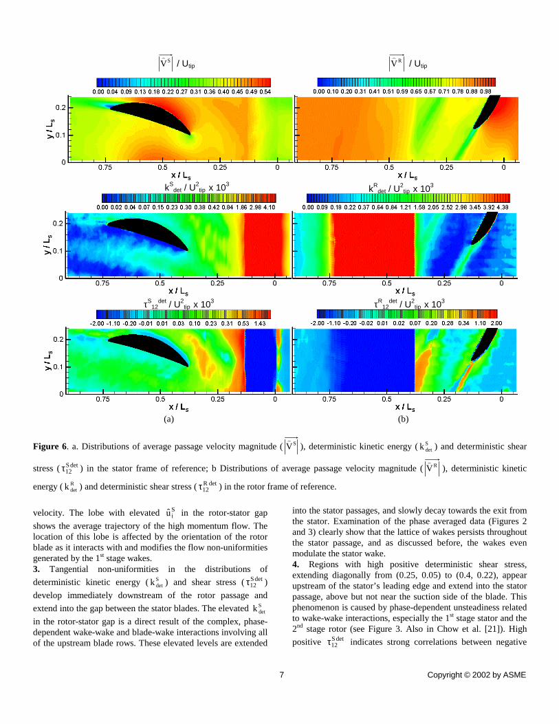
Figures 6a and 6b show the average-passage velocity
magnitude, deterministic kinetic energy and deterministic shear stress distributions, in the stator and rotor frames of reference, respectively. Consistent with the reference frame, all the rotor phases are averaged out in the stator frame of reference, and all the stator phases are averaged out in the rotor frame of reference. Several observations can be readily made from these distributions: In the stator frame of reference (figure 6a) 1. The high momentum region on the suction side of the blade and the structure of the stator wake are clearly visible in the average-passage velocity distribution. The boundary layer on the suction side becomes significantly thicker at x/LS>0.62, but there is no flow separation (no reverse flow), and then generates a large wake zone.
2. Significant tangential non-uniformity in Siu exists in the
gap between the rotor and the stator. “Potential flow” (non-viscous) effects associated with the presence of the stator blade increase with decreasing distance from the leading edge, particularly at x/LS>0.32. Another major contributor, especially at 0.13<x/LS<0.3 (immediately downstream of the rotor passage) is the tangential non-uniformities caused by interaction of the rotor blades with the 1st stage rotor and stator wakes, discussed briefly in the first part of this paper and in more details in Chow et al.[21]. These (phase-dependent) interactions modulate the distributions of both the momentum being generated by the rotor, and the 1st stage non-uniformities as they are advected through the rotor passage. Consequently, the distribution and magnitude of the high momentum region forming on the rotor suction side and extending in to the rotor wake (see Figures 2 and 3), becomes phase dependent. As an illustrating example, in Figure 2 (t/TR=0.6) and at x/Ls=0.2, the region with high velocity is bounded on its bottom side (at y/Ls=0.14) by a segment of the 1st stage stator wake. As this phase-dependent high momentum region is advected downstream, it also has a phase-dependent trajectory. Consequently, specific regions in the rotor-stator gap are periodically exposed to high momentum flow, whereas other regions are not, resulting in a non-uniform average passage
Copyright © 2002 by ASME
(a) (b)
Figure 6. a. Distributions of average passage velocity magnitude ( SV�
), deterministic kinetic energy ( Sdetk ) and deterministic shear
stress ( det S12τ ) in the stator frame of reference; b Distributions of average passage velocity magnitude ( RV
�), deterministic kinetic
energy ( Rdetk ) and deterministic shear stress ( det R
12τ ) in the rotor frame of reference.
kSdet / U
2tip x 103 kR
det / U2tip x 103
τS12
det / U2tip x 103 τR
12det / U2
tip x 103
SV�
/ Utip RV�
/ Utip
velocity. The lobe with elevated Siu in the rotor-stator gap
shows the average trajectory of the high momentum flow. The location of this lobe is affected by the orientation of the rotor blade as it interacts with and modifies the flow non-uniformities generated by the 1st stage wakes. 3. Tangential non-uniformities in the distributions of
deterministic kinetic energy ( Sdetk ) and shear stress ( det S
12τ )
develop immediately downstream of the rotor passage and
extend into the gap between the stator blades. The elevated Sdetk
in the rotor-stator gap is a direct result of the complex, phase-dependent wake-wake and blade-wake interactions involving all of the upstream blade rows. These elevated levels are extended
8 7
into the stator passages, and slowly decay towards the exit from the stator. Examination of the phase averaged data (Figures 2 and 3) clearly show that the lattice of wakes persists throughout the stator passage, and as discussed before, the wakes even modulate the stator wake. 4. Regions with high positive deterministic shear stress, extending diagonally from (0.25, 0.05) to (0.4, 0.22), appear upstream of the stator’s leading edge and extend into the stator passage, above but not near the suction side of the blade. This phenomenon is caused by phase-dependent unsteadiness related to wake-wake interactions, especially the 1st stage stator and the 2nd stage rotor (see Figure 3. Also in Chow et al. [21]). High
positive det S12τ indicates strong correlations between negative
Copyright © 2002 by ASME

and positive, horizontal and vertical, fluctuating (cyclic) phase averaged velocity components. Such an occurrence is an indicator for enhanced “deterministic mixing”. Note that the
high positive det S12τ region coincides with the lower edge of the
high Sdetk layer. Above it, coinciding with the upper half of the
elevated Sdetk layer, the deterministic shear stress is slightly
negative. Thus, the high Sdetk region contains layers of shear
stresses with opposite signs, a phenomenon that one would
expect to find in wakes (or jets). However, the high Sdetk does
not coincide with the lobe of high average-passage velocity. This disagreement may be a result of potential flow effects that modify the velocity distribution near the leading edge of the stator. 5. A narrow band of negative deterministic stresses develops along the suction side of the blade boundary layer up to about x/Ls=0.65, and then stops in the region where the boundary layer becomes significantly wider. Phase dependent variations in the flow near the wall, due to interactions with the lattice of wakes of the previous blades, discussed and illustrated briefly earlier in this paper (see also Chow et al [18]), is the primary cause for this phenomenon. Note that the sign of the stress is opposite to the sign of Reynolds shear stresses that would develop in the boundary layer. Preliminary analysis indicates that, the deterministic production in this region as well as within the stator passages is negative, indicating a transport of energy from the phase averaged (unsteady) flow to the average-passage flow. 6. In the aft region of the stator suction boundary layer the shear stress changes sign and becomes positive. Downstream of the stator trailing edge one can identify two high stress layers
with opposite signs The regions of high Sdetk in the stator wake
coincide with both layers, i.e. the deterministic kinetic energy is high at the same place that the shear stress is high. In the rotor frame of reference, (Figure 6b) 1. Regions with low average-passage momentum in the rotor frame of reference (��
��u i
R) are evident in both rotor wakes that are located within the sample area. The first is trailing from the blade and the second is generated by another blade located above it. 2. The highest levels of deterministic kinetic energy (kdet
R ) are found within the rotor wakes. Wake-wake interactions, such as the shearing and bending of the rotor wake by the segmented 1st
stage stator, discussed before (and is the primary topic of Chow et al., [21]), are the primary cause for this phenomenon. Elevated levels of kdet
R can also be seen on the pressure side of the blade. They are a result of phase dependent variations in velocity that occur as the rotor chops of the 1st stage stator wake, and cuts through the center-line of the 1st stage rotor wake. The resulting flow non-uniformities are then convected along the blade surface and interact with the rotor wake, generating the kinks (or meandering of the rotor wake – see
9 9
Figure 4), regions with concentrated vorticity and turbulent hot spots (Chow et al., [21]). The deterministic kinetic energy levels are also elevated upstream and within the rotor blade passages, mostly due to the transport of wakes generated by the blade of the 1st stage through the passages. 3. Wide regions with low but significant positive
deterministic shear stress, det R12τ , form on both sides of the rotor
blade. Examination of the phase average data suggests that these “halos” are a result of phase-dependent flow non-uniformities, caused by interactions of the rotor blade with the wakes of the 1st stage (chopping of the 1st stage stator wake and splitting the 1st stage rotor wake). Clear evidence for these non-uniformities is provided by comparing the two phases in Figure 4. 4. Parallel layers with elevated levels of positive and negative shear stresses develop in the wake of the rotor blade, with the positive layer reaching higher magnitudes. Upstream of the stator passage the shear stress distribution within the (upper) wake becomes completely positive and its magnitude increases. Examination of the phase averaged velocity distributions and flow angle in this region (not shown, see Chow et al., [18]) indicates that the flow angle within the rotor wake increases (in the absolute frame of reference) just upstream of the stator wake. This angle change alters the sign of the deterministic shear stress.
5. Regions of elevated deterministic stresses kdetR and det R
12τ
extend downstream of both stator passages. As mentioned before, rotor wake segments transported through the stator passage modify the phase-averaged flow downstream of the stator, and generate deterministic stresses.
Comparison Between Turbulent and Deterministic stresses
This section compares the distributions and magnitudes of Reynolds stresses to the distributions and magnitudes of deterministic stresses. Recall that the turbulent stresses are calculated from the difference between the instantaneous and phase averaged data, whereas the deterministic stresses are calculated from the difference between the phase averaged and average-passage data. Previous studies have already reported that the deterministic stresses can be of similar or higher magnitude than the turbulent stresses (Rhie et al. [4], Lejambre et al. [5], Sinha et al. [16]). Figure 7 compares the present
distributions of Sdetk to k (at t/TR=0.7), and det S
12τ to vu ′′− (also
at t/TR=0.7) at three axial locations: 30% of the stator axial chord upstream from the stator leading edge, mid stator passage, and 30% stator axial chord downstream from the stator trailing edge. As is evident, in all three axial locations the turbulent kinetic energy levels are much higher than the corresponding deterministic kinetic energy levels. In all three cases, the high k values are associated with turbulent wakes, the 1st stage stator wake in Figure 7a, the wake lattice in Figure 7b, as well as the 2nd stage stator wake (high peak) and wake lattice (lower broad peak) in Figure 7c. The only exception with
Copyright © 2002 by ASME

(a) (b) (c)
Figure 7. Comparisons between k and Sdetk (upper row), and between vu ′′− and det S
12τ (lower row) at: a. x/LS=0.271, b. x/LS=0.553
and c. x/LS=0.835. Values at t/TR=0.7 are selected as representatives for the turbulent parameters.
(a) (b) (c)
Figure 8. Comparisons between k and kdetR (upper row), and between vu ′′− and det R
12τ (lower row). a. x/LS=0.172, b. x/LS=0.212 and
c. x/LS=0.355. Values at t/TR=0.5 that correspond to the same rotor location are selected as representatives for the turbulent parameters.
10
10 Copyright © 2002 by ASME

similar (but still lower) values is the elevated Sdetk region in the
gap between the rotor and the stator. Conversely, the levels of the turbulent and deterministic shear stresses are comparable to each other. At x/LS= 0.271 (upstream of the stator), there is even
a region where det S12τ is higher than vu ′′− (0.05<y/LS<0.15). As
discussed before, wake-wake interactions involving the 1st stage rotor and stator wakes, as well as the 2nd stage rotor wake, generate high phase-dependent unsteadiness in this region. Within and downstream of the stator passage, the turbulent shear stresses are higher than the deterministic stresses. It is also evident that trends of the Reynolds and deterministic stresses differ substantially.
The turbulent and deterministic stresses in the rotor frame of reference are compared in Figure 8. It shows the distributions
of k, kdetR , vu ′′− and det R
12τ at three axial locations, namely
30%, 60%, and 170% of the rotor axial chordlengths downstream from the rotor trailing edge. The third sample is located close to the stator. We use the turbulent kinetic energy and shear stress at t/TR=0.5, consistent with the location of the rotor in Figure 6b. In all three cases the regions with elevated levels of deterministic kinetic energy are located within the rotor wake, in a (x/Ls=0.172) and b (x/Ls=0.212) the wake is generated by the blade shown in the sample area, and in c (x/Ls=0.355) the wake is generated by the blade above the sample area. Consequently, one can identify corresponding peaks in the distributions of turbulent kinetic energy. As explained before, interactions of the rotor wake with the wakes of the 1st stage are the causes for both. In a and b the levels of kdet
R are substantially lower than the levels of k, whereas in plane c the values are comparable. However, the k distributions contain additional peaks that occur, at least for planes a and b, as the 1st stage stator wake crosses the sample plane. Interestingly, the k peaks associated with the rotor wake decay quickly with axial distance, whereas the broader, “far field” wake of the 1st stage stator maintains almost the same level of turbulent kinetic energy (note the differences in scales).
Close to the rotor blade, at x/Ls=0.212 (Figure 8b), the
levels of det R12τ are elevated within the rotor wake, but are still
lower than the turbulent shear stress. Both stresses have layers with opposite signs, consistent with the previous discussion, although this trend is clearer in the Reynolds stress. At x/Ls=0.212 we miss the positive stress peaks of the wake, but capture the negative peaks at y/Ls=0.01 (see Figure 6b). Conversely, at x/Ls=0.355, the plane with the highest values of
det R12τ in the rotor-stator gap, the deterministic shear stress is
significantly higher than the turbulent stress. As noted before, at this location the magnitude of the shear stress is affected by the stator-induced changes to flow angle. In regions outside the rotor wake the deterministic shear stresses are very small.
11
11
Effect of the non-uniformities present in the average-passage field on the work input
In this section we examine the effect of flow non-uniformities associated with blade-wake and wake-wake interactions on the performance of rotor, expressed in terms of the work input of the stator row. Figures 9a and b show the distributions of average-passage vertical/lateral (almost tangential) velocity components in the stator frame of reference ( ˆ u 2
S = ˆ v S ), downstream and upstream of the rotor row, respectively. The rotor blade row occupies the space between x/LS=0.0 and x/LS =0.132. As is evident from these plots, the distribution of ˆ v S becomes non-uniform in the tangential direction immediately downstream of the rotor row. Although tangential non-uniformities are expected close to the stator blade because of the potential flow effects (Shang et al. [22]), the 0.14<x/LS<0.21 region is located more than 50% of the stator axial chord upstream of the stator leading edge. Hence, this region should have minimal potential flow effect associated with the 2nd stage stator blade. Nevertheless, the non-uniformities are evident. Substantial non-uniformities in ˆ v S occur also upstream of the rotor blade row (Figure 9b). Figure 10 compares the average-passage lateral velocity distributions in two axial planes, one is located 55% of the rotor axial chord upstream of the rotor leading edge (x/LS=-0.07), and the other is located 16% of the rotor axial chord downstream of the rotor trailing edge (x/LS=0.153). The maximum tangential variation of ˆ v S Utip downstream of the blade row is 7%, and 55%
upstream of the rotor. We have already established that the non-uniformities upstream of the rotor are predominantly caused by the presence of the 1st stage stator wakes. Within the 1st stage stator wake the lateral velocity is low (the stator is designed to generate an axial flow), whereas in the regions outside of these wakes ˆ v S Utip is higher, presumably due to a decreased
effectiveness with increasing distance from the blade. Downstream of the rotor blade row, the increased lateral velocities in the 0.13<y/LS<0.245 region is caused by the interaction of the rotor blade with the 1st stage rotor and stator wakes, discussed briefly in this paper and is the main topic of Chow et al. [21].
In order to demonstrate the effect of these non-uniformities on the specific work input of the blade row, let’s define two parameter W1
* and W2*
W1* =
ˆ v dS − ˆ v u, av
S
ˆ v d,avS − ˆ v u,av
S W2
* =ˆ v d
S − ˆ v uS
ˆ v d,avS − ˆ v u ,av
S (10)
where the subscripts u and d refer to the selected planes upstream and downstream of the rotor, respectively, and the subscript “av” refers to average over the tangential direction. Both W1
* and W2* are indicators for the tangential non-
uniformities in the average specific work input, resulting, in the present case from interactions with the 1st stage wakes. W2
*
accounts for the non-uniformity at the inlet to the rotor and W1*
does not. Figure 11 shows the distributions of W1* and W2
* . The
Copyright © 2002 by ASME

peak to peak variations in W1* and W2
* are 7% and 13%, respectively. These results are a clear indication that the interaction of the rotor blade with the wake of the 1st stage cause substantial variations in the performance of the rotor. This conclusion holds in spite of the relatively high blade spacings of the present turbomachine, a distance of 1.95 times the rotor axial chord from the 1st stage stator, and 6.5 rotor axial chords from the 1st stage rotor (see Table 1). CONCLUSIONS
PIV measurements are performed in the 2nd stage of a 2 stage axial turbomachine. Phase averaged flow fields are obtained for 10 different rotor phases covering the entire stage. Phase averaged results are then used to obtain the average-passage flow fields and distributions of deterministic stress in the entire stage both in the stator and rotor frames of references. The measured phase averaged flow field is extremely complex and appears to consist of a lattice of wakes. Wake-wake and wake-blade interactions cause substantial phase-dependent, non-uniformities and high turbulence both in the rotor and stator frames of references. These phenomena generate high deterministic stresses and considerable variations in the performance of the rotor.
The average-passage flow fields in the stator frame of reference contain substantial tangential non-uniformities in the average-passage velocity, as well as in the distributions of deterministic kinetic energy and shear stress in the rotor - stator gap. Close to the stator blade, the non-uniformity in the velocity distribution is mainly due to the potential field of the stator. However close to the rotor blade within the gap, the non-uniformities are due to the interaction of the 1st stage rotor and stator wakes with the rotor blades. Tangential non-uniformities and elevated levels of deterministic kinetic energy and shear stress inside the gap is a direct result of the complex, phase-dependent wake-wake and blade-wake interactions involving all of the upstream blade rows. These elevated levels are extended into the stator passages, and slowly decay towards the exit from the stator. The distributions of the deterministic kinetic energy and the shear stress within the gap also show a wake (or jet) like character, consisting of a high deterministic kinetic energy region and layers of shear stresses with opposite signs. Phase dependent variations in the flow near the suction side of the stator blade results in negative deterministic stresses along the suction side of the blade boundary layer. The sign of the stress is opposite to the sign of Reynolds shear stresses that would develop in the boundary layer. Preliminary analysis indicates that, the deterministic production in this region as well as within the stator passages is negative, indicating a transport of energy from the phase averaged (unsteady) flow to the average-passage flow. High levels of deterministic kinetic energy and shear stress are also found within the stator wake mainly due to the meandering of the stator wake, resulting from interaction with the wakes generated by upstream blade rows.
12
1
(a) (b) Figure 9. Distributions of average-passage lateral velocity component, ˆ v S Utip , (a) downstream and (b) upstream of the
rotor blade row. The rotor blade occupies the 0.0<x/LS<0.132 region. Flow from right to left.
Figure 10. Distributions of ˆ v S Utip in sample planes located
upstream (x/Ls=-0.07) and downstream (x/Ls=0.153) of the rotor blade row.
Figure 11. Tangential non-uniformity in the average-passage Specific Work Input (W*) at 16 % rotor axial chord downstream (at x/LS=0.153) of the rotor blade row due to the non-uniform average-passage lateral velocity distribution
Sv / Utip Sv / Utip
2 Copyright © 2002 by ASME
In the rotor frame of reference, the deterministic kinetic energy levels are maximum inside the rotor wakes. Wake-wake interactions, such as the shearing and bending of the rotor wake by the segmented 1st stage stator are the primary cause for this phenomenon. Wide regions with low but significant positive deterministic shear stress form on both sides of the rotor blade. Examination of the phase average data suggests that these “halos” are a result of phase-dependent flow non-uniformities, caused by interactions of the rotor blade with the wakes of the 1st stage (chopping of the 1st stage stator wake and splitting the 1st stage rotor wake). Elevated levels of positive and negative shear stresses also develop in the wake of the rotor blade, with the positive layer reaching higher magnitudes. Upstream of the stator passage the shear stress distribution within the rotor wake becomes completely positive and its magnitude increases, mainly due to phase dependent flow angle variations in this region.
The deterministic stresses are also compared to the turbulent (Reynolds) stresses. It is observed that the turbulent kinetic energy levels are generally higher than the deterministic kinetic energy levels, whereas the shear stress levels are comparable, both in the rotor and stator frames of reference. At certain locations the deterministic shear stresses are substantially higher than the turbulent shear stresses, such as close to the stator blade in the rotor frame of reference. At this location the magnitude of the shear stress is affected by the stator-induced changes to the flow angle.
The substantial tangential non-uniformities in the lateral velocity component result in 13% variations in the specific work input of the rotor. Thus, in spite of the relatively large blade row spacings in the present turbomachine, the non-uniformities in flow structure have significant effects on the overall performance of the system.
It has to be kept in mind that all the measurements reported in this paper are two-dimensional and at mid-span. We have actually recorded 2D data on two other radial planes (the hub and the tip). Mid-span measurements are just the starting point of our studies. Our future measurements will also include 3D stereoscopic PIV measurements in different radial planes. ACKNOWLEDGEMENTS
This project is sponsored by AFOSR under grant No. F49620-01-1-0010. The program manager is Dr. T. Beutner. Support for construction/assembly of the facility was also provided by ONR, under grant number N00014-99-1-0965. The program officer is P. Purtell. We would also like to thank Yury Ronzhes, Stephen King, Ali Pinarbasi, Madan M. Guin for their contribution to the construction of the facility, and Khoon Ooi from Able Corporation, for designing the rotor and stator blades REFERENCES [1] Adamczyk, J. J., 1985, “Model Equation for Simulating Flows in Multistage Turbomachinery,” ASME Paper No. 85-GT-226.
13 13
[2] Adamczyk J.J., Mulac R.A., Celestina M.L., 1986, “A Model for Closing the Inviscid Form of the Average-Passage Equation System,” ASME Paper No. 86-GT-227 [3] Adamczyk J.J.; Celestina M.L.; Beach T.A.; Barnett M., 1990, “Simulation Of Three Dimensional Viscous Flow Within A Multistage Turbine,” ASME J. of Turbomachinery, 112, p. 370 [4] Rhie C.M.; Gleixner A.J.; Spear D.A.; Fischberg C.J.; Zacharias R.M., 1998 “Development and Application Of A Multistage Navier-Stokes Solver. Part I: Multistage Modeling Using Body Forces and Deterministic Stresses, ” ASME J. Turbomachinery 120, p. 205. [5] Lejambre C.R.; Zacharias R.M.; Biederman B.P.; Gleixner A.J.; Yetka C.J., 1998, “Development And Application Of A Multistage Navier-Stokes Solver. Part II: Application To A High Pressure Compressor Design,” ASME J. Turbomachinery 120, 215. [6] Busby J.; Sondak D.; Staubach B.; Davis R., 2000, “Deterministic Stress Modeling of a Hot Gas Segregation in a Turbine,” J. of Turbomachinery 122, 62. [7] Dawes, W. N., 1992, “Towards Improved Throughflow Capability: The Use of Three-Dimensional Viscous Flow Solvers in A Multistage Environment,” ASME J. of Turbomachinery, 114, pp. 8-17. [8] Denton, J. D., 1992, “The Calculation of Three-Dimensional Viscous Flow Through Multistage Turbomachines,” ASME J. of Turbomachinery, 114, pp. 18-26. [9] Van de Wall A.G., Kadambi J.R., Adamczyk J.J., 2000, “A Transport Model for the Deterministic Stresses Associated With Turbomachinery Blade Row Interactions,” ASME J. of Turbomachinery, 122, pp. 593-603 [10] Meneveau C.; Katz J., 2001, “A Deterministic Stress Model for Rotor-Stator Interactions in Simulations of Passage-Averaged Flow,” Submitted to Journal of Fluids Engineering [11] Prato, J., Lakshminarayana B., Suryavamshi N., 1997, “Exit Flow Field of an Embedded Stator in a Multi-Stage Compressor,” J. of Propulsion and Power, Vol. 13 No. 2, pp. 169-177. [12] Prato, J., Lakshminarayana B., Suryavamshi N., 1998, “Steady and Unsteady Three-Dimensional Flow Field Downstream of an Embedded Stator in a Multi-Stage Axial Flow Compressor Part I: Unsteady Velocity Field,” ASME Paper No. 98-GT-521 [13] Suryavamshi N., Lakshminarayana B., Prato J., 1998, “Steady and Unsteady Three-Dimensional Flow Field Downstream of an Embedded Stator in a Multi-Stage Axial Flow Compressor Part II: Composite Flow Field,” ASME Paper No. 98-GT-522 [14] Suryavamshi N., Lakshminarayana B., Prato J., 1998, “Steady and Unsteady Three-Dimensional Flow Field Downstream of an Embedded Stator in a Multi-Stage Axial Flow Compressor Part III: Deterministic Stress and Heat Flux Distribution and Average-Passage Equation System,” ASME Paper No. 98-GT-523
Copyright © 2002 by ASME
[15] Sinha, M., and Katz, J., 2000, “Quantitative Visualization of the Flow in a Centrifugal Pump With Diffuser Vanes-I: On Flow Structures and Turbulence,” ASME J. Fluids Eng., 122, pp. 97-107. [16] Sinha, M., Katz, J., and Meneveau, C., 2000, “Quantitative Visualization of the Flow in a Centrifugal Pump With Diffuser Vanes-II: Addressing Passage-Averaged and Large-Eddy Simulation Modeling Issues in Turbomachinery Flows,” ASME J. Fluids Eng., 122, pp. 108-116. [17] Uzol, O., Chow, Y. C., Katz, J., and Meneveau, C., 2001, “Unobstructed PIV Measurements within an Axial Turbo-Pump Using Liquid and Blades with Matched Refracted Indices,” 4th International Symposium on Particle Image Velocimetry, Göttingen, Germany, September 17-19, 2001. Also submitted to Experiments in Fluids. [18] Chow Y.C., Uzol O. Katz J., Meneveau C., 2002, “An Investigation of Axial Turbomachinery Flows Using PIV in an Optically-Unobstructed Facility,” To be presented at The 9th International Symposium on Transport Phenomena and Dynamics of Rotating Machinery, Honolulu, Hawaii, February 10-14, 2002 [19] Roth, G. I., Mascenik, D. T., and Katz, J., 1999, “Measurements of The Flow Structure and Turbulence Within A Ship Bow Wave,” Physics of Fluids, 11, No. 11, pp. 3512-3523. [20] Roth, G. I., and Katz, J., 2001, “Five Techniques for Increasing the Speed and Accuracy of PIV Interrogation,” Meas. Sci. Technol. 12, pp. 238-245. [21] Chow Y.C., Uzol O., Katz J., 2002, “Flow Non-Uniformities And Turbulent “Hot Spots” Due To Wake-Blade And Wake-Wake Interactions In A Multistage Turbomachine,” To be presented at ASME Turbo Expo International Gas Turbine Institute Conference, June 3-6 2002 , Amsterdam, The Netherlands. [22] Shang T., Epstein A.H., Giles M.B., Sehra A.K., 1993, “Blade Row Interaction Effects on Compressor Measurements,” J. of Propulsion and Power Vol. 9, No. 4, pp. 569-578
14
14 Copyright © 2002 by ASME