experimental investigation of injection and combustion
TRANSCRIPT
Experimental investigation of injection and combustion processes in marine gas engines using constant volume rig
Vladimir KrivopolianskiiDepartment of Marine Technology, NTNU21 March 2019
Tro
ndhe
im–
Gjø
vik
–Å
lesu
nd
2
Agenda
• Motivation • Development of an experimental combustion facility• Study of diesel injection• Study of alternative fuel for pilot diesel injection• Study of high-pressure gas injection• Conclusion• Further work
3
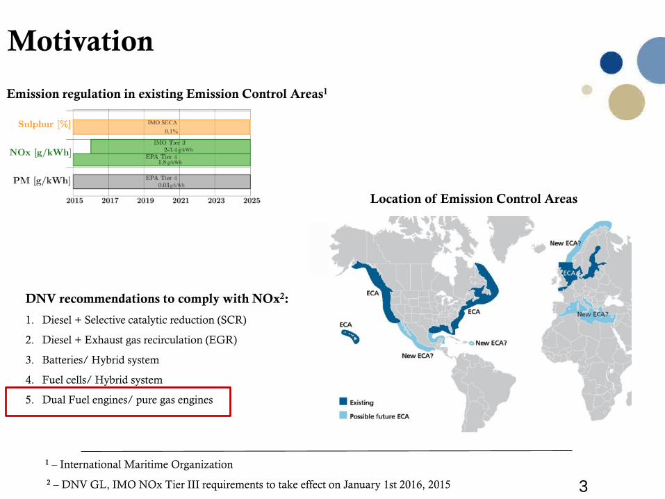
Motivation
1 – International Maritime Organization
Emission regulation in existing Emission Control Areas1
Location of Emission Control Areas
DNV recommendations to comply with NOx2:
1. Diesel + Selective catalytic reduction (SCR)
2. Diesel + Exhaust gas recirculation (EGR)
3. Batteries/ Hybrid system
4. Fuel cells/ Hybrid system
5. Dual Fuel engines/ pure gas engines
2 – DNV GL, IMO NOx Tier III requirements to take effect on January 1st 2016, 2015
4
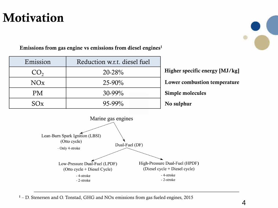
Motivation
Emission Reduction w.r.t. diesel fuel
CO2 20-28%
NOx 25-90%
PM 30-99%
SOx 95-99%
Emissions from gas engine vs emissions from diesel engines1
Higher specific energy [MJ/kg]
Lower combustion temperature
Simple molecules
No sulphur
1 – D. Stenersen and O. Tonstad, GHG and NOx emissions from gas fueled engines, 2015
5
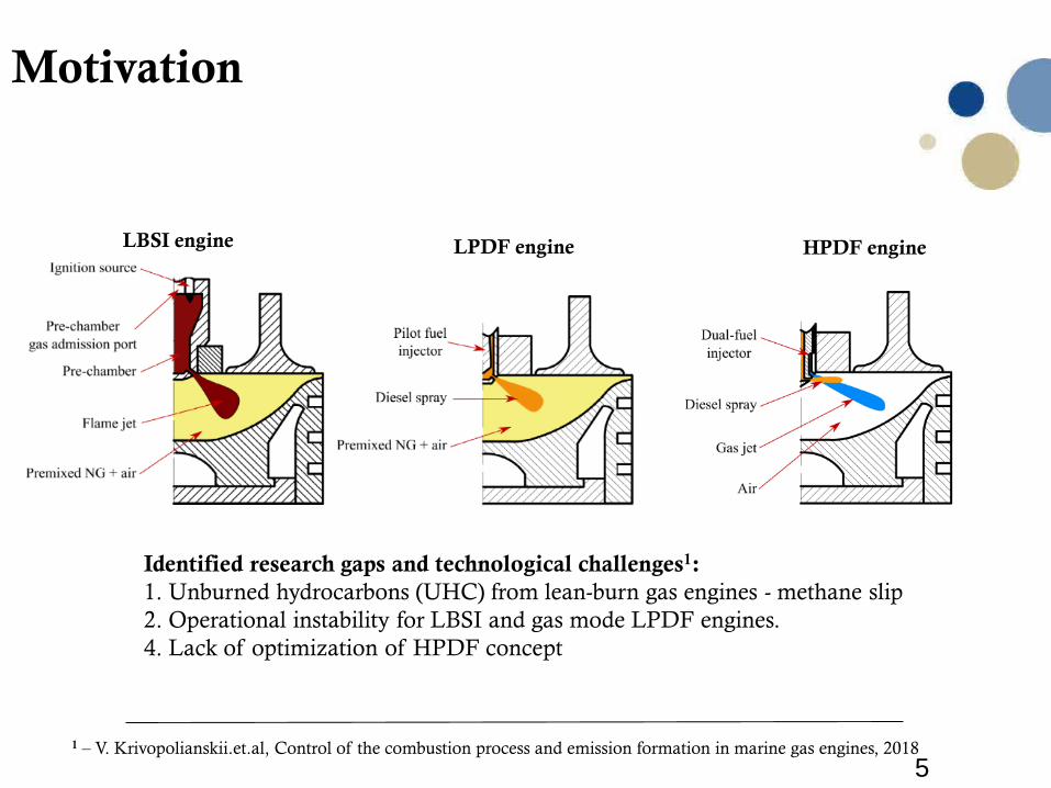
LBSI engine LPDF engine HPDF engine
Motivation
Identified research gaps and technological challenges1: 1. Unburned hydrocarbons (UHC) from lean-burn gas engines - methane slip2. Operational instability for LBSI and gas mode LPDF engines. 4. Lack of optimization of HPDF concept
1 – V. Krivopolianskii.et.al, Control of the combustion process and emission formation in marine gas engines, 2018
6
Research objectives:
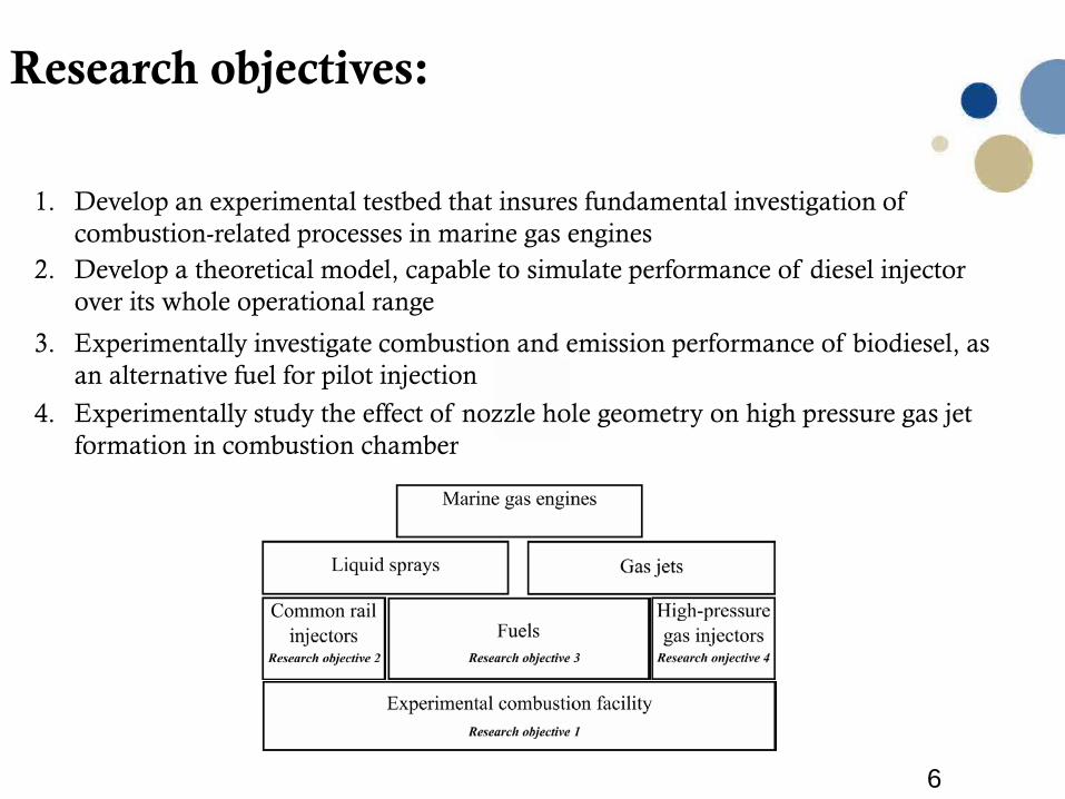
1. Develop an experimental testbed that insures fundamental investigation of combustion-related processes in marine gas engines
4. Experimentally study the effect of nozzle hole geometry on high pressure gas jet formation in combustion chamber
3. Experimentally investigate combustion and emission performance of biodiesel, as an alternative fuel for pilot injection
2. Develop a theoretical model, capable to simulate performance of diesel injector over its whole operational range

7
Research objective 1:
Experimental research facility
8
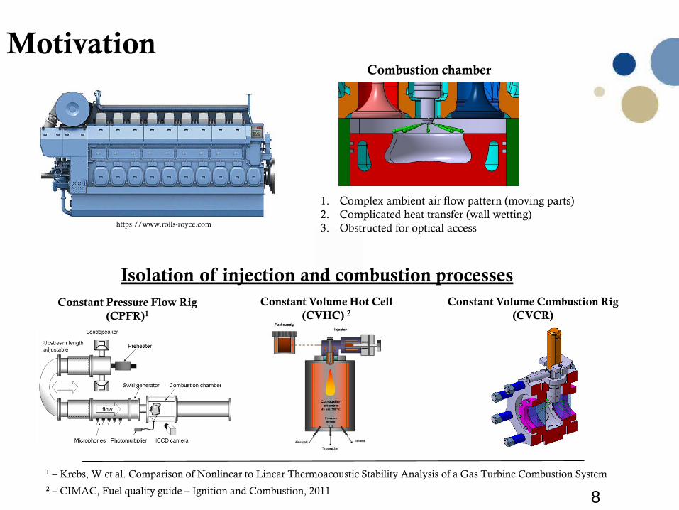
MotivationCombustion chamber
1. Complex ambient air flow pattern (moving parts)2. Complicated heat transfer (wall wetting)3. Obstructed for optical access
Constant Pressure Flow Rig (CPFR)1
Constant Volume Hot Cell (CVHC) 2
Constant Volume Combustion Rig (CVCR)
Isolation of injection and combustion processes
https://www.rolls-royce.com
1 – Krebs, W et al. Comparison of Nonlinear to Linear Thermoacoustic Stability Analysis of a Gas Turbine Combustion System2 – CIMAC, Fuel quality guide – Ignition and Combustion, 2011
9
Constant volume chambers
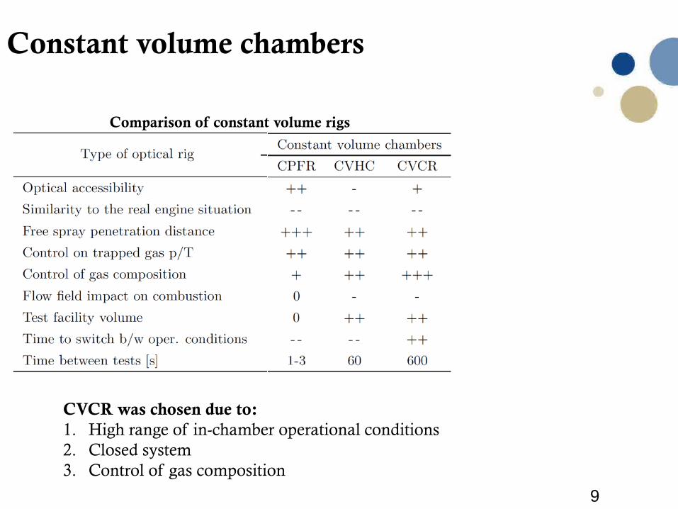
Comparison of constant volume rigs
CVCR was chosen due to:1. High range of in-chamber operational conditions2. Closed system3. Control of gas composition
10
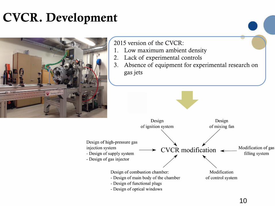
CVCR. Development
2015 version of the CVCR:1. Low maximum ambient density2. Lack of experimental controls3. Absence of equipment for experimental research on
gas jets
11
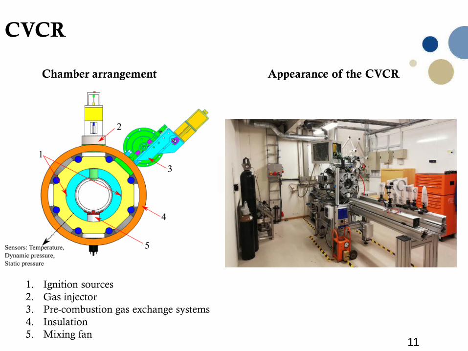
CVCR
Appearance of the CVCRChamber arrangement
1. Ignition sources2. Gas injector3. Pre-combustion gas exchange systems4. Insulation5. Mixing fan
12
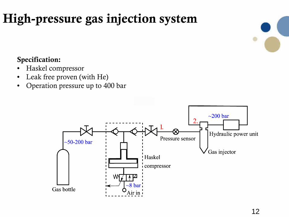
High-pressure gas injection system
Specification:• Haskel compressor• Leak free proven (with He)• Operation pressure up to 400 bar
13
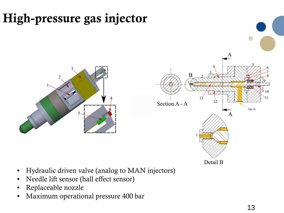
High-pressure gas injector
• Hydraulic driven valve (analog to MAN injectors)• Needle lift sensor (hall effect sensor)• Replaceable nozzle • Maximum operational pressure 400 bar
14
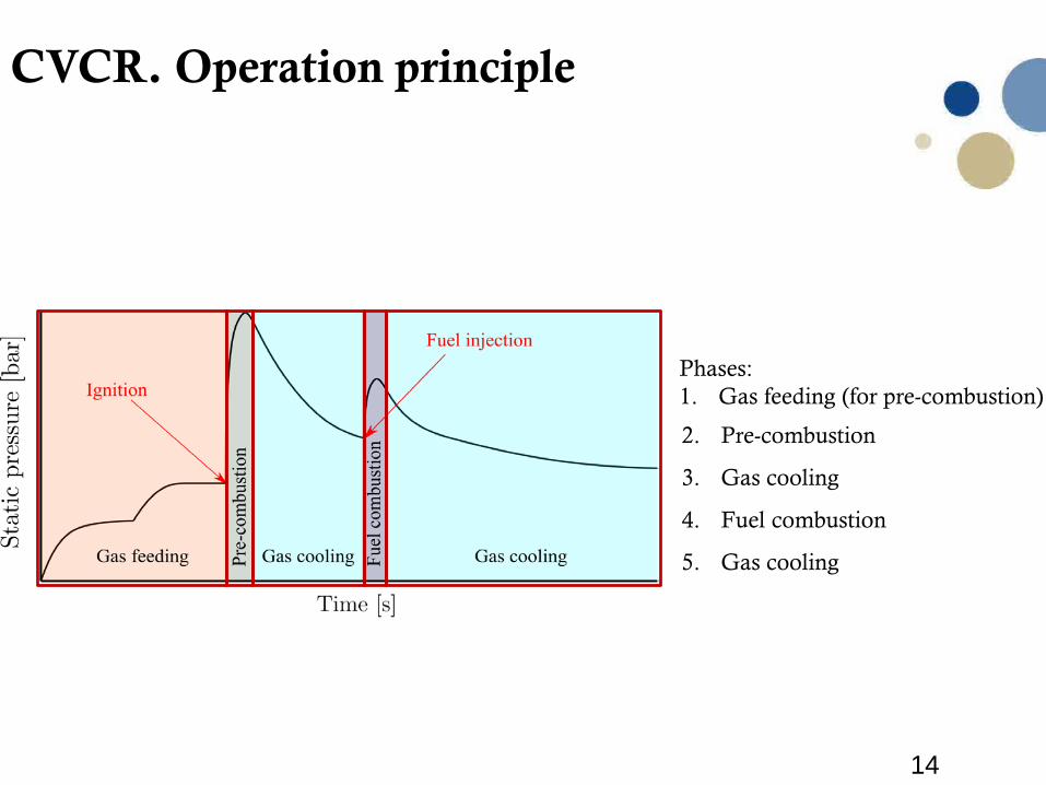
CVCR. Operation principle
Phases:1. Gas feeding (for pre-combustion)
2. Pre-combustion
3. Gas cooling
4. Fuel combustion
5. Gas cooling
15
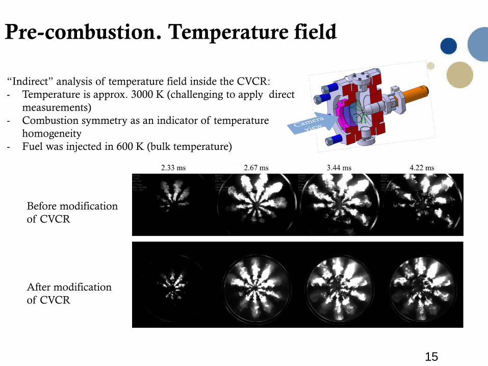
Pre-combustion. Temperature field
Before modificationof CVCR
After modificationof CVCR
“Indirect” analysis of temperature field inside the CVCR:- Temperature is approx. 3000 K (challenging to apply direct
measurements)- Combustion symmetry as an indicator of temperature
homogeneity- Fuel was injected in 600 K (bulk temperature)
16
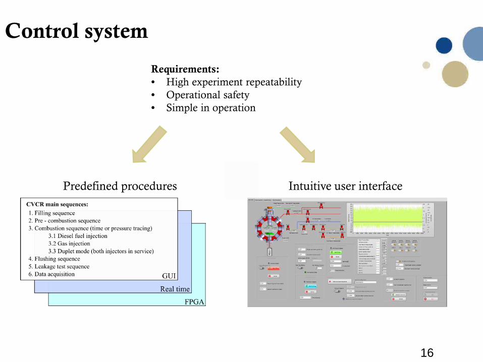
Control system
Requirements:• High experiment repeatability• Operational safety• Simple in operation
Intuitive user interfacePredefined procedures
17
Research objective 2:
Common rail injectors
18
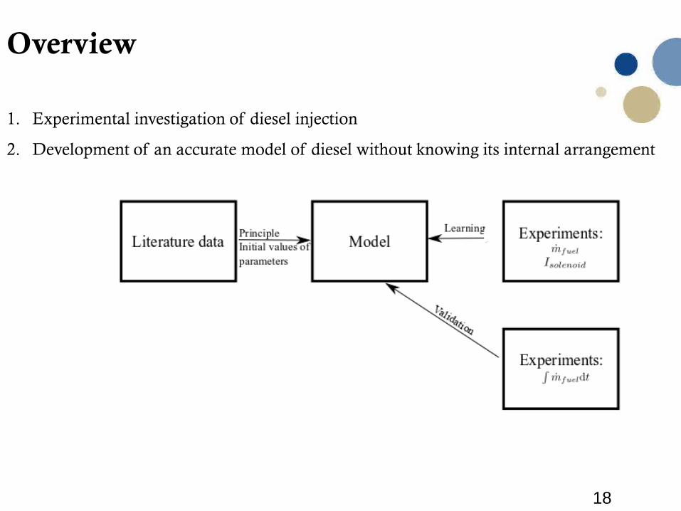
Overview
1. Experimental investigation of diesel injection
2. Development of an accurate model of diesel without knowing its internal arrangement
19
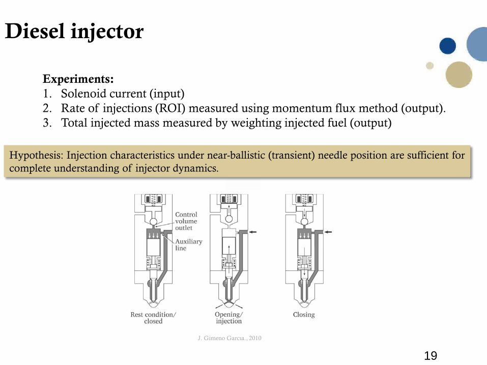
Diesel injector
Experiments:1. Solenoid current (input)2. Rate of injections (ROI) measured using momentum flux method (output).3. Total injected mass measured by weighting injected fuel (output)
Hypothesis: Injection characteristics under near-ballistic (transient) needle position are sufficient for complete understanding of injector dynamics.
J. Gimeno Garcıa., 2010
20
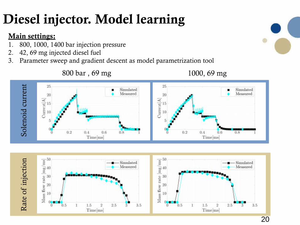
Diesel injector. Model learningSo
leno
id c
urre
ntR
ate
of in
ject
ion
800 bar , 69 mg 1000, 69 mg
Main settings: 1. 800, 1000, 1400 bar injection pressure2. 42, 69 mg injected diesel fuel3. Parameter sweep and gradient descent as model parametrization tool
21
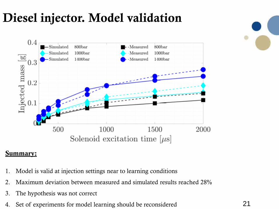
Diesel injector. Model validation
Summary:
1. Model is valid at injection settings near to learning conditions
2. Maximum deviation between measured and simulated results reached 28%
3. The hypothesis was not correct
4. Set of experiments for model learning should be reconsidered
22
Research objective 3:
Fuels
23
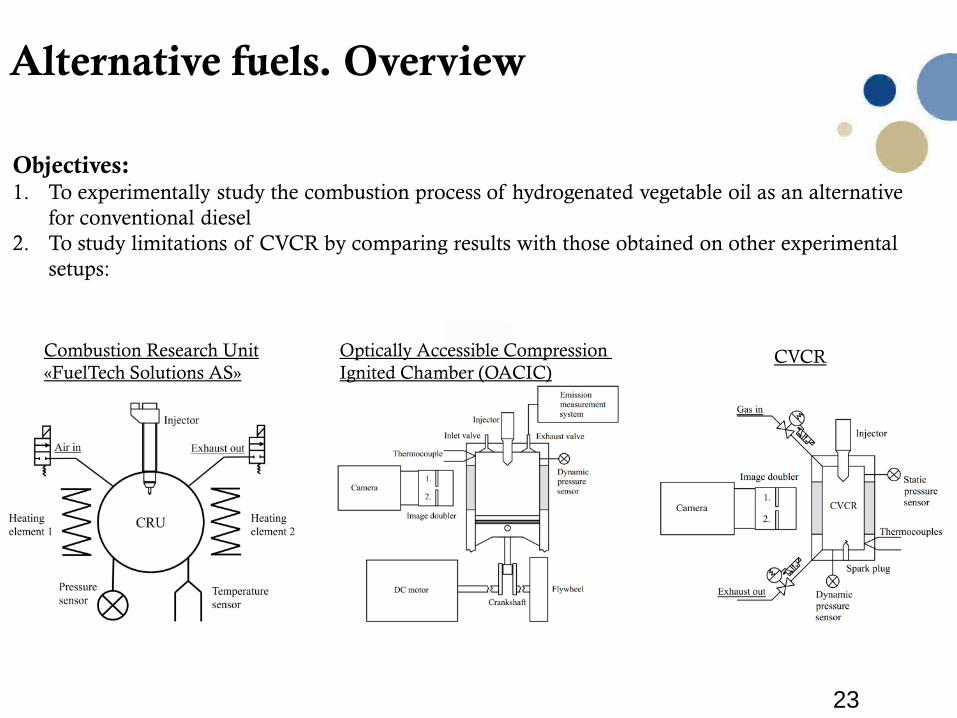
Alternative fuels. Overview
Objectives:1. To experimentally study the combustion process of hydrogenated vegetable oil as an alternative
for conventional diesel2. To study limitations of CVCR by comparing results with those obtained on other experimental
setups:
Optically Accessible Compression Ignited Chamber (OACIC)
Combustion Research Unit«FuelTech Solutions AS»
CVCR
24
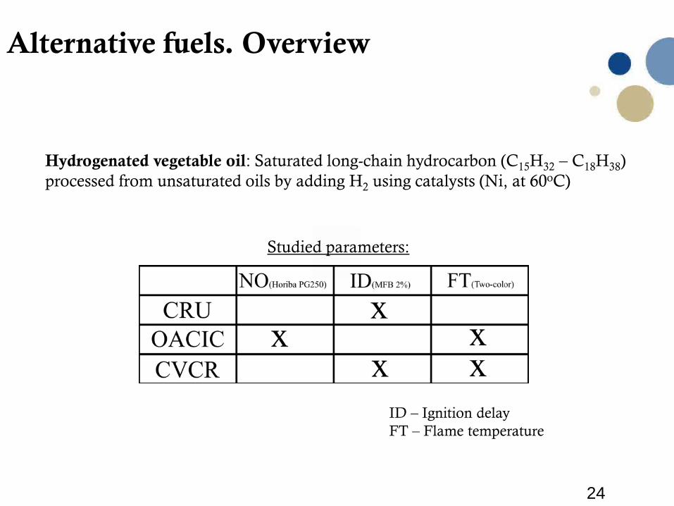
Alternative fuels. Overview
Hydrogenated vegetable oil: Saturated long-chain hydrocarbon (C15H32 – C18H38) processed from unsaturated oils by adding H2 using catalysts (Ni, at 60oC)
Studied parameters:
ID – Ignition delayFT – Flame temperature
25
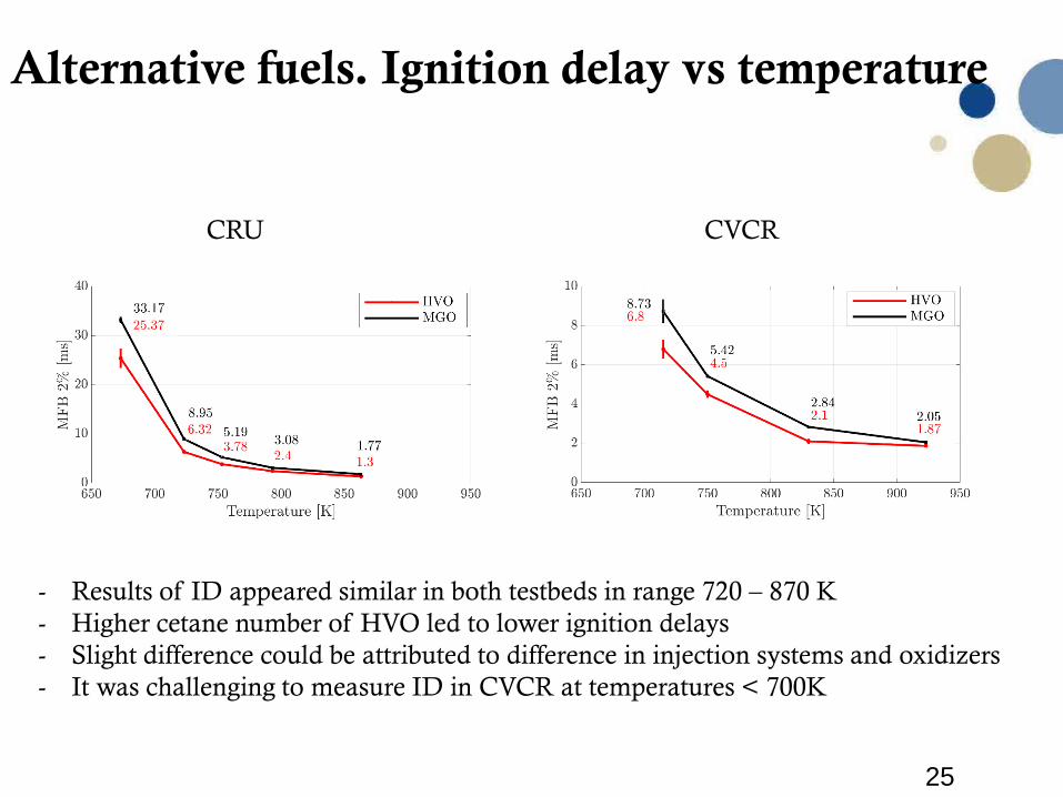
Alternative fuels. Ignition delay vs temperature
CRU CVCR
- Results of ID appeared similar in both testbeds in range 720 – 870 K- Higher cetane number of HVO led to lower ignition delays- Slight difference could be attributed to difference in injection systems and oxidizers- It was challenging to measure ID in CVCR at temperatures < 700K
26
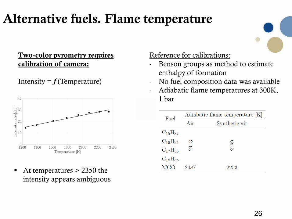
Alternative fuels. Flame temperature
Two-color pyrometry requires calibration of camera:
Intensity = f (Temperature)
At temperatures > 2350 the intensity appears ambiguous
Reference for calibrations:- Benson groups as method to estimate
enthalpy of formation- No fuel composition data was available- Adiabatic flame temperatures at 300K,
1 bar
27
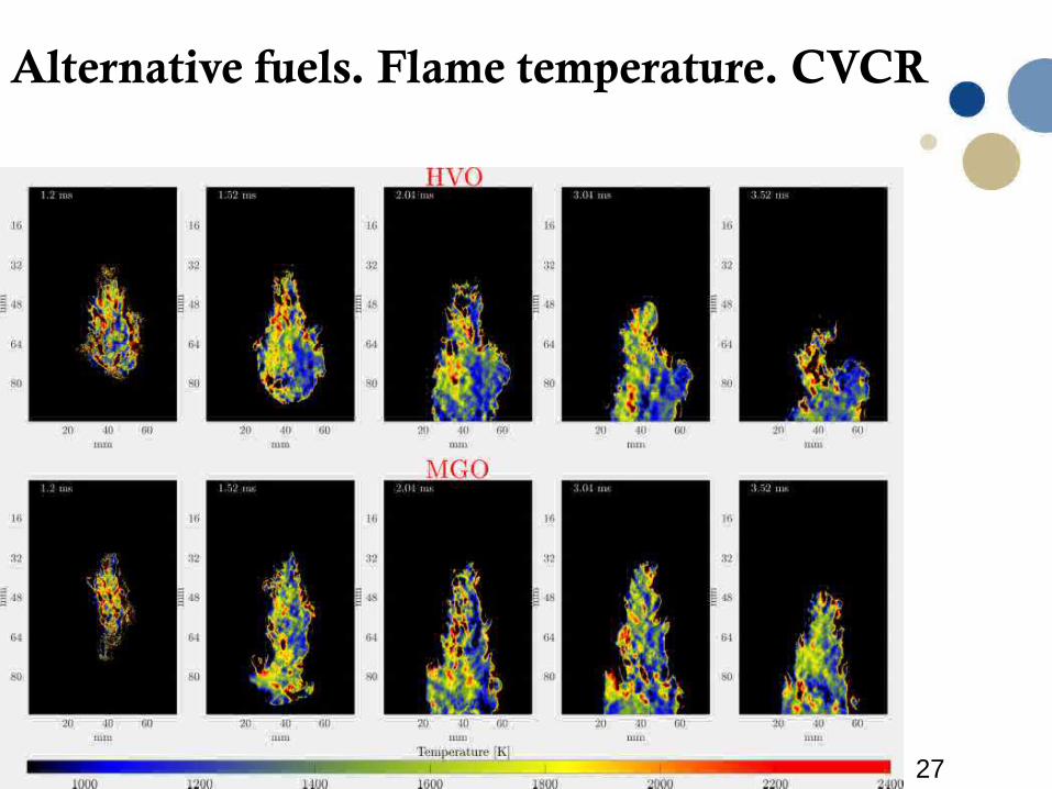
Alternative fuels. Flame temperature. CVCR
28
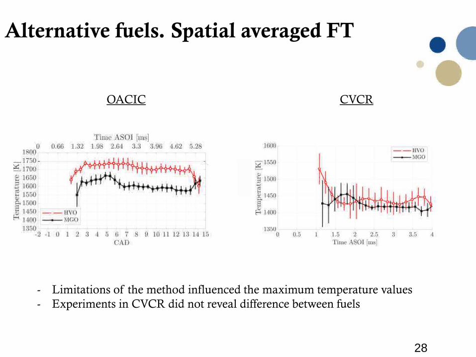
Alternative fuels. Spatial averaged FT
OACIC CVCR
- Limitations of the method influenced the maximum temperature values- Experiments in CVCR did not reveal difference between fuels
29
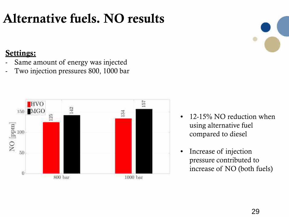
Alternative fuels. NO results
Settings:- Same amount of energy was injected- Two injection pressures 800, 1000 bar
• 12-15% NO reduction when using alternative fuel compared to diesel
• Increase of injection pressure contributed to increase of NO (both fuels)
30
Research objective 3:
High pressure gas injectors
31
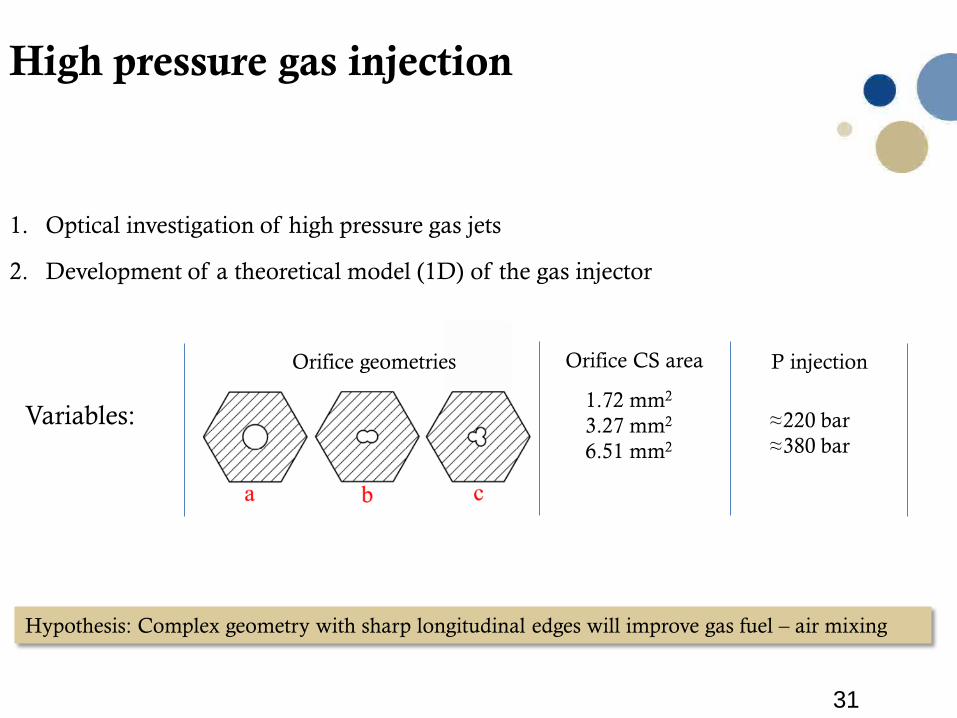
High pressure gas injection
1. Optical investigation of high pressure gas jets
Orifice geometries
Variables:
P injection
≈220 bar≈380 bar
Orifice CS area
1.72 mm2
3.27 mm2
6.51 mm2
Hypothesis: Complex geometry with sharp longitudinal edges will improve gas fuel – air mixing
2. Development of a theoretical model (1D) of the gas injector
32
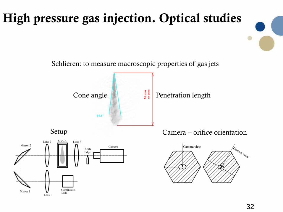
High pressure gas injection. Optical studies
Setup Camera – orifice orientation
Schlieren: to measure macroscopic properties of gas jets
Penetration lengthCone angle
33
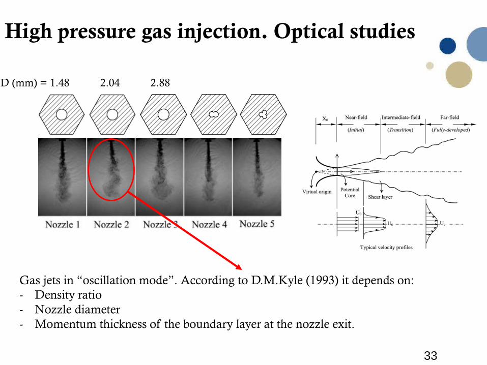
High pressure gas injection. Optical studies
Gas jets in “oscillation mode”. According to D.M.Kyle (1993) it depends on:- Density ratio- Nozzle diameter - Momentum thickness of the boundary layer at the nozzle exit.
D (mm) = 1.48 2.04 2.88
34
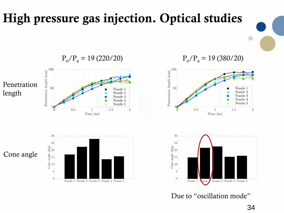
High pressure gas injection. Optical studies
Po/Pa = 19 (380/20)
Penetration length
Cone angle
Due to “oscillation mode”
Po/Pa = 19 (220/20)
35
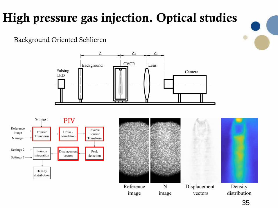
High pressure gas injection. Optical studies
Background Oriented Schlieren
PIV
36
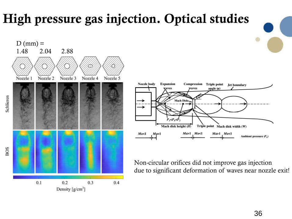
High pressure gas injection. Optical studies
D (mm) = 1.48 2.04 2.88
Non-circular orifices did not improve gas injection due to significant deformation of waves near nozzle exit!
37
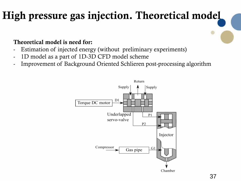
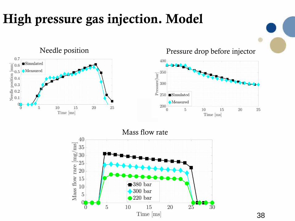
High pressure gas injection. Theoretical model
Theoretical model is need for:- Estimation of injected energy (without preliminary experiments)- 1D model as a part of 1D-3D CFD model scheme- Improvement of Background Oriented Schlieren post-processing algorithm
38
High pressure gas injection. Model
Needle position
Mass flow rate
Pressure drop before injector
39
1. CVCR was developed to experimental investigation on combustion process in marine
gas engines ( mainly HPDF concept)
2. Theoretical model of diesel injector was developed. Method to study diesel injector
with unknown architecture was suggested.
3. Hydrogenated vegetable oil as was studied as alternative fuel for pilot injection and
proved to be a good candidate for replacement of conventions diesel fuels.
4. Effect of non-circular orifice on gas jet formation was optically studied in CVCR.
Conclusion
40
• Suggest a model/scheme “to connect’’ the CVCR with an internal
combustion engine
• Further develop the two-color pyrometry method
• Develop a 3D model of the gas injector to study different nozzle
geometries/ gas types
• Study dual-fuel injection/combustion (diesel – gas injections)
Further work

41
Thank you for your attention!
Questions?
Q/A
42
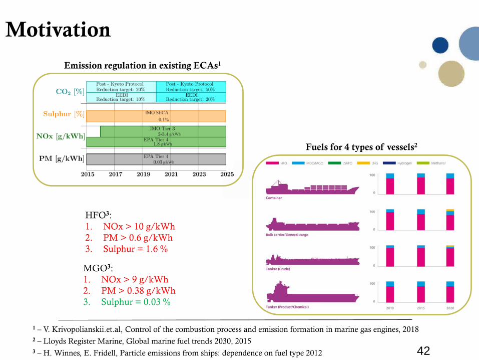
Motivation
Fuels for 4 types of vessels2
1 – V. Krivopolianskii.et.al, Control of the combustion process and emission formation in marine gas engines, 2018
3 – H. Winnes, E. Fridell, Particle emissions from ships: dependence on fuel type 2012
Emission regulation in existing ECAs1
MGO3:1. NOx > 9 g/kWh2. PM > 0.38 g/kWh3. Sulphur = 0.03 %
2 – Lloyds Register Marine, Global marine fuel trends 2030, 2015
HFO3:1. NOx > 10 g/kWh2. PM > 0.6 g/kWh3. Sulphur = 1.6 %
HFO3:1. NOx > 10 g/kWh2. PM > 0.6 g/kWh3. Sulphur = 1.6 %
MGO3:1. NOx > 9 g/kWh2. PM > 0.38 g/kWh3. Sulphur = 0.03 %
43
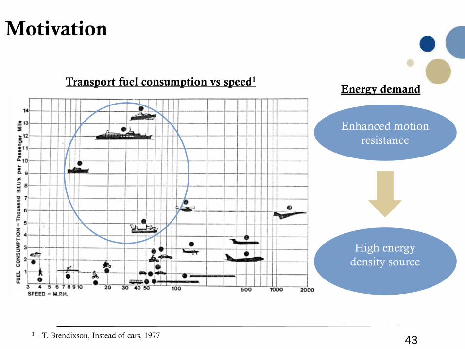
Motivation
Transport fuel consumption vs speed1
Enhanced motion resistance
Energy demand
High energy density source
1 – T. Brendixson, Instead of cars, 1977
44
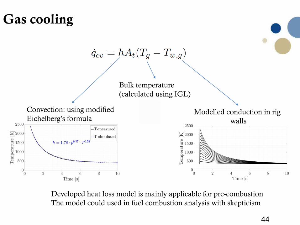
Gas cooling
Bulk temperature(calculated using IGL)
Modelled conduction in rig walls
Convection: using modified Eichelberg’s formula
Developed heat loss model is mainly applicable for pre-combustion The model could used in fuel combustion analysis with skepticism
45
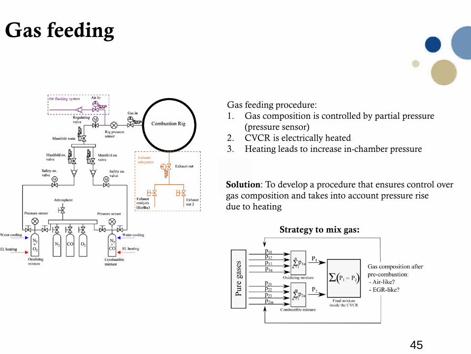
Gas feeding
Gas feeding procedure:1. Gas composition is controlled by partial pressure
(pressure sensor)2. CVCR is electrically heated3. Heating leads to increase in-chamber pressure
Solution: To develop a procedure that ensures control over gas composition and takes into account pressure rise due to heating
Strategy to mix gas:
46
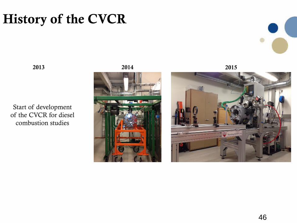
History of the CVCR
2014 20152013
Start of developmentof the CVCR for diesel
combustion studies
48
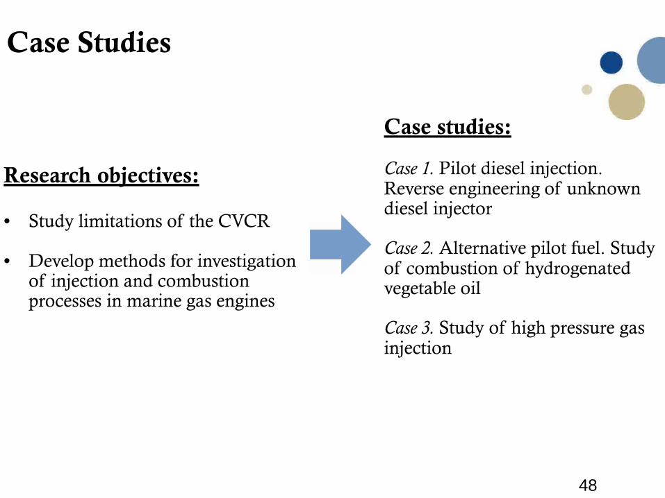
Research objectives:
• Study limitations of the CVCR
• Develop methods for investigation of injection and combustion processes in marine gas engines
Case Studies
Case studies:
Case 1. Pilot diesel injection. Reverse engineering of unknown diesel injector
Case 2. Alternative pilot fuel. Studyof combustion of hydrogenated vegetable oil
Case 3. Study of high pressure gas injection
50
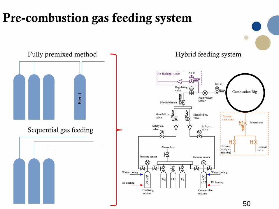
Pre-combustion gas feeding system
Fully premixed method
Sequential gas feeding
Hybrid feeding system
Ble
nd
51
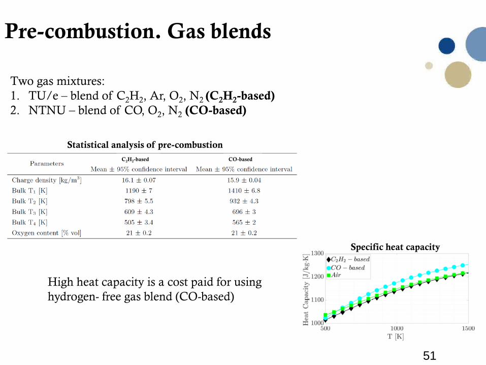
Pre-combustion. Gas blends
Two gas mixtures:1. TU/e – blend of C2H2, Ar, O2, N2 (C2H2-based) 2. NTNU – blend of CO, O2, N2 (CO-based)
C2H2-based CO-based
Statistical analysis of pre-combustion
Specific heat capacity
High heat capacity is a cost paid for using hydrogen- free gas blend (CO-based)
52
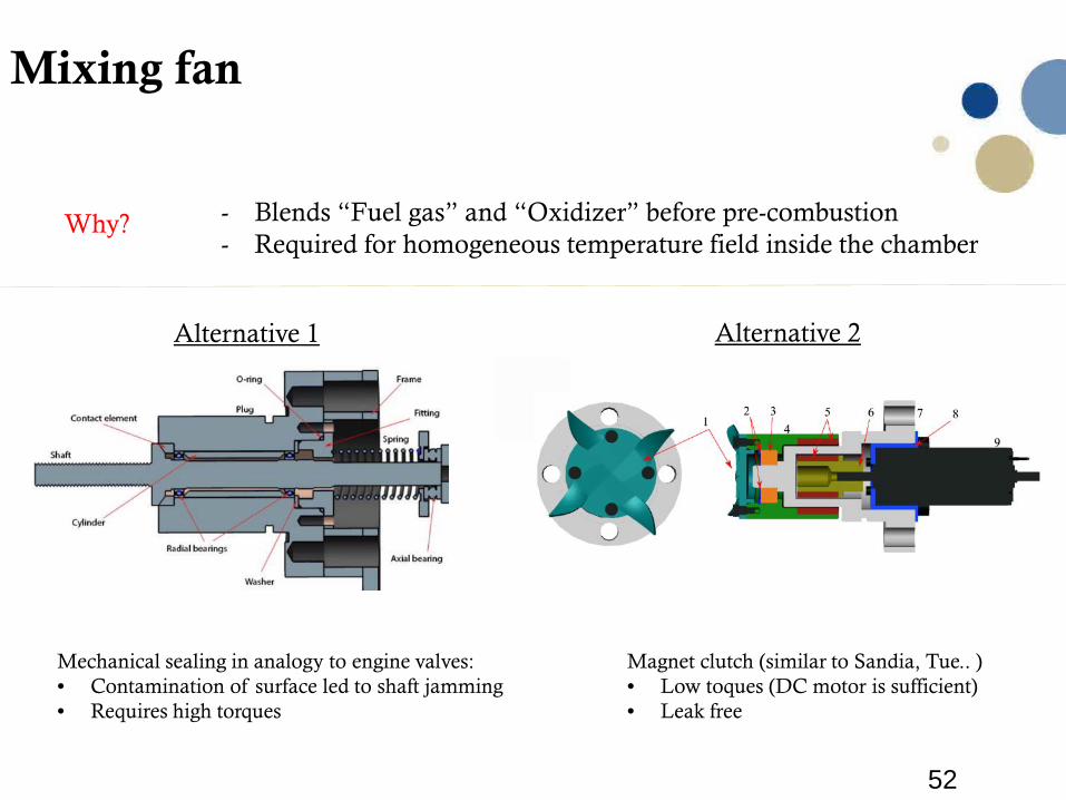
Mixing fan
- Blends “Fuel gas” and “Oxidizer” before pre-combustion- Required for homogeneous temperature field inside the chamber
Magnet clutch (similar to Sandia, Tue.. )• Low toques (DC motor is sufficient)• Leak free
Alternative 1 Alternative 2
Mechanical sealing in analogy to engine valves:• Contamination of surface led to shaft jamming• Requires high torques
Why?
53
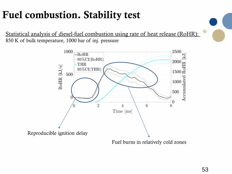
Fuel combustion. Stability test
Statistical analysis of diesel-fuel combustion using rate of heat release (RoHR): 850 K of bulk temperature, 1000 bar of inj. pressure
Reproducible ignition delay
Fuel burns in relatively cold zones
54
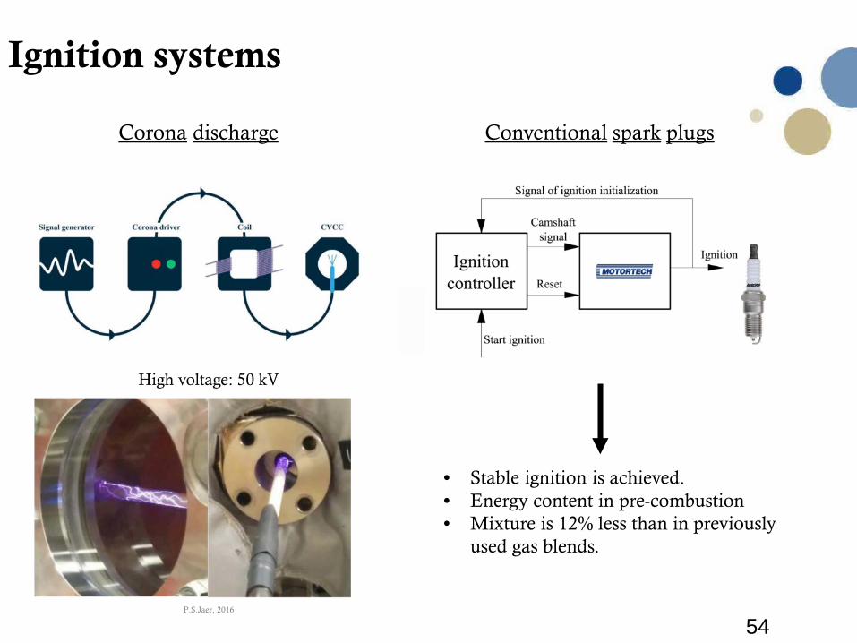
• Stable ignition is achieved. • Energy content in pre-combustion • Mixture is 12% less than in previously
used gas blends.
Ignition systems
Corona discharge Conventional spark plugs
High voltage: 50 kV
P.S.Jaer, 2016
55
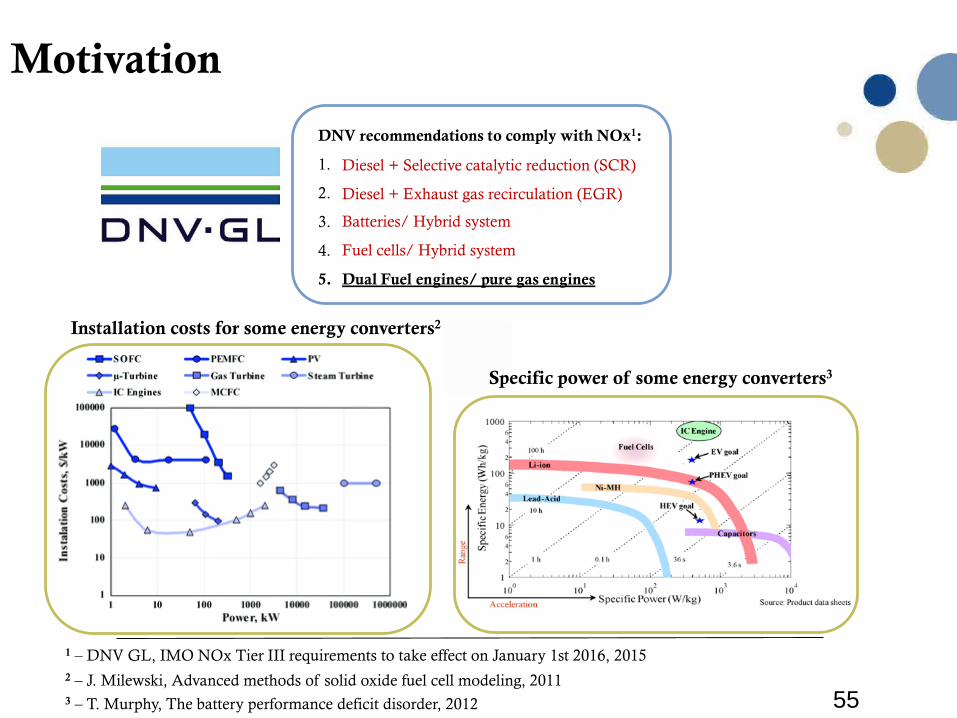
Motivation
DNV recommendations to comply with NOx1:
1. Diesel + Selective catalytic reduction (SCR)
2. Diesel + Exhaust gas recirculation (EGR)
3. Batteries/ Hybrid system
4. Fuel cells/ Hybrid system
5. Dual Fuel engines/ pure gas engines
3 – T. Murphy, The battery performance deficit disorder, 2012
2 – J. Milewski, Advanced methods of solid oxide fuel cell modeling, 2011
1 – DNV GL, IMO NOx Tier III requirements to take effect on January 1st 2016, 2015
Specific power of some energy converters3
Installation costs for some energy converters2
Batteries/ Hybrid system
Fuel cells/ Hybrid system
Diesel + Selective catalytic reduction (SCR)
Diesel + Exhaust gas recirculation (EGR)
56
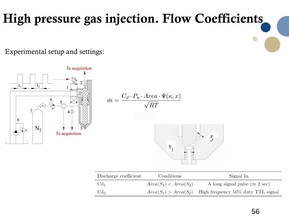
High pressure gas injection. Flow Coefficients
Experimental setup and settings:
57
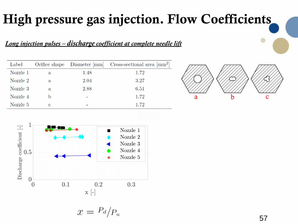
High pressure gas injection. Flow Coefficients
Long injection pulses – discharge coefficient at complete needle lift
58
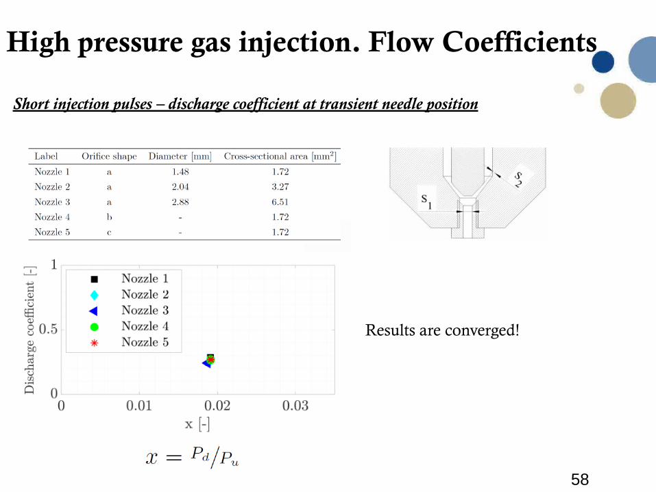
High pressure gas injection. Flow Coefficients
Short injection pulses – discharge coefficient at transient needle position
Results are converged!

59
60
Acknowledgments:M. MalinF. GranØ. KristiansenT. HaugenN. LefebvreD. KochK. MindeO. PaulsenP. Risberg