experimental investigation into wear and tool life of
TRANSCRIPT
Tehnički vjesnik 25, 6(2018), 1603-1610 1603
ISSN 1330-3651 (Print), ISSN 1848-6339 (Online) https://doi.org/10.17559/TV-20161128094553 Original scientific paper
Experimental Investigation into Wear and Tool Life of Milling Cutter PVD Coated Carbide Inserts While Armox 500 Steel Hard Milling
Jozef MAJERÍK, Rozmarína DUBOVSKÁ, Jaroslav JAMBOR, Robert ČEP, Jiří KRATOCHVÍL, Karel KOUŘIL
Abstract: The goal of the submitted paper is to evaluate the dependence of tool life T = f(vc) in hard rough face milling process of the Armox 500 steel through the PVD coated cemented carbide cutting material with SNHF 1204EN-SR-M1 tool insert geometry. Practical tests of choice material were performed in the milling machine tool with vertical axis. The effect of applied cutting conditions on the surface finish, tool life, wear of cutting tool, such as flank wear and surface structure of applied cutting inserts, was investigated during the performed experiments. The goal of this article is to research the impact of various cutting speeds values during the process of hard face rough milling. Experiments are carried out with an aim to study tool life, surface finish and flank wear prediction on the PVD coated cemented carbide cutting material in hard milling processes. This has been observed through the REM and mathematical method of least squares for this characterization. The presented approach and acquired results will prove themselves helpful in understanding the machinability of Armox 500 steel during the hard milling process. Keywords: carbide inserts; flank wear; hard milling; milling cutter; tool life; tool wear 1 INTRODUCTION
Over the last couple of years, hard machining technology has won the attention of many a manufacturer in the whole world, particularly the manufacturers of dies and moulds dealing with this type of production and generally used cutting materials, such as coated cemented carbides in roughing. Traditionally, core and cavity of the said material are produced in the hardened state, making use of spark erosion. In the meantime, new techniques have been invented for cutting special types of hard steels, and in most instances they have been machined directly through hard rough milling, using variations of programming cycles and strategies paths of cutting tools, as well as in their hardened state.
Workpiece materials have a hardness range from 45 HRC to 64 HRC. Hard milling of complex shapes or moulds and dies for applications of rough face milling technology is drawn on the use of new milling strategies, or on modern construction of cutting tools coated with new generations of multilayer coatings. The most common shape and cutting tool geometry is a milling cutter with changeable cutting tools. For the application of hard rough milling the most common are changeable cemented carbide cutting tool inserts, especially the P and H types as the cutting geometry of these inserts (shown in Fig. 1 and 2) has been designed for the application of hard milling technology.
Hence, they provide for the optimal tool life and also the desired productivity of hard materials machining, such as hard steel. The advantages of using this type of milling cutters with changeable carbide cutting inserts include achieving shorter machining times and reducing the number of cutting operations. These all are very good conditions for ensuring the required tool life of used cutting inserts in demanding operating conditions including undoubtedly the Armox500 hard face rough milling process. Cutting tools are designed to be capable of hard milling of safe and reliable rough machining utilizing certain types of large milling cutters, up to a smaller diameter with changeable carbide cutting inserts. Hard milling is the most common machining technology for operations without cooling (dry machining), in particular,
when milling cutters with changeable cutting inserts are being used. Hard milling of hardened material with the hardness of 45 to 63 HRC is most often performed in dry environment, also with the use of cutting plates negative cutting tool geometry. In the hard milling process with coated cemented carbide inserts or solid carbide milling cutters, each cutting tooth of the tool is in interaction with the machined material through plastic deformation. The resulting heat is absorbed into the chips to the cutting tool and also to the workpiece. Each changeable cutting insert clamped in the milling cutter being in contact with the constantly created chips during hard milling is heated up to 300 °C to 700 °C. During hard milling the cutting inserts continuously approach the cut and retract from the cut, thus cooled by the air, in addition to cutting. Cooling of carbide inserts during hard milling in the air is low and each insert remains at a constant moderate temperature. Cemented carbide can withstand temperatures of up to 800 °C without any damage. In the case of cooling emulsion during hard milling, each cutting insert during the retraction of each cut is heated to a cutting temperature and then rapidly cooled. There is a large temperature gradient, and as the cemented carbide is cyclically heated and rapidly cooled it causes high internal stress, fatigue and cracking along the cutting edge during the hard machining process. Therefore, it is preferable for hard milling with coated carbide inserts or with solid carbide milling cutters not to use the coolant. One of the questions in hard milling technology centers mainly on tool wear, and impacts the machinability of hard steels [4, 5]. Tool life represents a very important research element, which determines the machining performance. Tool wear significantly actuates the quality of machined surfaces. Tool wear belongs to the significant criteria in the tool life specification. As the carbide cutting insert reaches the tool wear gauge, cutting edge will then be destroyed and cannot therefore be applied. Tool wear may generally be understood as a progressive phenomenon, and the wear rate usually depends on the cutting insert and machined material, insert geometry, coolant, technological conditions, and machine tool. The cutting tool discarding standard for hard rough face milling process is applied and the stating values are considered under the ISO Standard 3685 applicable for tool life screening in the work authored
Jozef MAJERÍK et al.: Experimental Investigation into Wear and Tool Life of Milling Cutter PVD Coated Carbide Inserts While Armox 500 Steel Hard Milling
1604 Technical Gazette 25, 6(2018), 1603-1610
by Gopalsamy et al. [8] and Senthil Kumar et al. [14]. Heat-treated parts by hardening were exposed to intense operating conditions. Surface integrity plays a role in all these events. Hence, cutting tool wear has a substantial impact directly on surface integrity and quality [6]. Large numbers of scientific studies have been conducted over the decades, in order to examine the influence of machining conditions on flank wear [7, 12].
The authors [10, 17] made use of a number of sorts of machined and cutting materials in rough face milling process investigations. In this paper, mathematical method of least squares and REM characterization is carried out in hard milling process of Armox 500 steel. Face milling technology is connected with high plastic pressure and a very huge strain grade, consequently causing a substantial growth in the cutting insert temperature near the shear area. Direct heat generation on tool-material interface has a significant effect on dimensional changes due to thermal deformation in machining process or surface defect caused by oxidation, as outlined in [13]. During the performed experiments, several machining parameters have been specified. It can be said that Armox has been machined to the PVD carbide inserts. Performed research has been done with the goal to analyze performance with respect to cutting conditions, flank wear, and tool life to appreciate the efficiency of applied cemented carbide cutting inserts. This has been noticed and documented using a REM microscope of Tescan Vega TS 5135 type. The same observation has been made by Pokorný et al. [15].
An et al. [1] and Li et al. [11] reported experimental studies and investigations into hard milling technological process of high strength steels using cemented carbide cutting inserts. Investigated factors of surface integrity involving all researched characteristics were addressed in all following articles [1, 11].
Authors such as Çalişkan et al. [4, 5] studied cutting tool wear and machining performance on various types of PVD coatings on carbides substrates during hard machining process, or performance of cemented carbides with multiple PVD coatings, based on behaviour of the machined surface. Throughout the hard machining experiments, it was noticed that wear regimes in used carbide inserts involved abrasion and oxidation affecting the cutting tool geometry. Prevailing carbide insert damages observed included notch wear, build-up-edge, and chipping. For that reason, the depth of notch wear was established to compute the tool life [4, 5].
Gopalsamy et al. [8] reported investigations into hard machining of hard tool steels. Experiments were carried out with the aim to analyse performance of cutting conditions existing within hard milling technology with regard to material removal rate (MRR), wear, tool life, and surface quality to recognize the efficiency of used cemented carbide cutting inserts for the applied milling cutters. This has been shown by the REM microscopy.
Cui, et al. [3] published tests of especially flank wear mechanisms noticing a fact that at increased cutting speed the effect of oxidation wear on the flank face becomes more dramatic, whereas the influence of adhesive wear subsequently decreases. All of these studies investigate the possibility of the machinability and achieved results prominently improve the hard milling process. Rough face milling process of hardened steels can generate breaking of
breakable fracture of the cutting tool edge. This is generally caused by cutting forces created within a hard milling process. For the practical assessment of the flank wear grade, width of the wear pads on the reverse of the VBk and the depth of the notch at the front-line of the KT (according to ISO 3685 standard) are the most conventionally used parameters. The strength of wear can influence machining parameters. According to Vasilko [16], cutting speed has a greater impact than the feed motion, while the impact of the depth of cut is minor. At hard rough face milling of Armox 500 steel, these are typically chosen as standard of the flank wear VBk, with inserted enhancement in cutting forces as the wear increases. Resistance of the work of cutting insert with a focus on VBk wear, may be defined by the tool life T per minutes of cutting time, the number of machined parts or per cutting tool path. In practice, we investigate to standard of wear, so that the ultimate is an optimal tool life.
Cutting conditions [18, 19] and increase of the tool wear cause intensive growth in friction forces, which results in the increase of the cutting force [20, 21].
Motorcu et al. [2] and Nath et al. [17] have supposed that tool life is commonly evaluated through parameters or influence of material properties formulated from a criterion based on wear for a special cutting technology. Accordingly, tool wear may be regarded as the first necessity of tool life. It is possible to say that flank wear research is one of the most significant tests that can be made in order to designate tool life and, as a consequence of this, to formulate machining parameters for obtaining a high stage of optimization in the machining technology.
2 EXPERIMENTAL PROCEDURE AND USED METHOD
Long-term cutting tools life testing in machining is defined by the international standard of ISO3685-E-77-05-15. The values of tool life that are deduced from the characteristic curves of tool wear on a given criterion wear VB for the flank face of the cutting insert or KT (the depth of the groove on the rake face) are inserted into the table and then into a graphical presentation. Long-term tool life tests on the cutting material usually depend on the cutting speed. Machining variables are recommended to be three to five times, the test is repeated with using one variable two to four times. Then the credibility of the achieved results is statistically guaranteed and properly determined. The criterion of tool wear VBk = 0.6 mm is designated for roughing, or VBk = 0.3 mm for finishing the structural steel. When machining hardened materials, it is necessary to specify the criterion VBk for at least half of the values. Taylor's equation of tool life has an explicit form as reported by Vasilko [16]:
mcTv vCT
c
−= . (1) Consequently, it is transcribed into the implicit form [9]:
1
ISOm
cv T C⋅ = (2)
With the help of linearisation of decimal logarithms the following form is determined [9]:
Jozef MAJERÍK et al.: Experimental Investigation into Wear and Tool Life of Milling Cutter PVD Coated Carbide Inserts While Armox 500 Steel Hard Milling
Tehnički vjesnik 25, 6(2018), 1603-1610 1605
ISO1log log logcv T Cm
− = (3)
When measured tool life was indicated as yi = logTi
with variables of cutting speeds being xi = log vci, then the determined linear regression of a single parameter is expressed in the form [9]:
0 0 1 1 ISO( log ) ( )iy b x b x m x C m x x= ⋅ + ⋅ = ⋅ − + ⋅ − (4)
While 1
logNci
i
vx
N== ∑ and
1
logNi
i
Ty
N== ∑ (5)
are the mean values, where: x0 - is the fictitious value, which is equal to 1 for the natural
gauge, but for the logarithmic gauge it equals log 10 = 1,
x1 - is the individual variable, b0 - is adjunct constant, which indicates an increase in the
axis y = log C, b1 - indicates tendency for the regression function and m =
−b1 = tanα, which is angle line, N- is a number of measurements (i = 1, 2, 3,…, 12)
By adjusting the equations with the method of least squares equation, the form for the −b1 = m. It is necessary to get a function into the form: yT = a + b·x
0)( 2
1=−∑
=
n
i
Ti
Ei yy (6)
After adjusting, we obtain Eqs. (7), (8) for the
calculation of parameters [9]:
2 2x y x yb
x x⋅ − ⋅
=−
(7)
a y b x= − ⋅ (8)
According to Eq. (7) parameter (8) is calculated, which in this case is the exponent (m) from Eq. (9):
1T m
T cmc
CT C vv
−= = ⋅ (9)
22
x yx yNm b
xxN
⋅⋅ −
= − = −
(10)
If yi = log Ti and xi = log vci is then:
( )22
log loglog log
loglog
ci ici i
cici
v Tv T
Nmv
vN
⋅⋅ −
=
−
∑ ∑∑
∑∑ (11)
where: log ci
iv
xN
= ∑ and log i
iT
yN
= ∑
By multiplying Eq. (10) [9] with N/N =1, it yields the equation for m:
( )22
log log log log
log logci i ci i
ci ci
N v T v Tm
N v v
⋅ ⋅ − ⋅=
⋅ −
∑ ∑ ∑∑ ∑
(12)
There is also the following form of Eq. (13) [9, 16]:
log log logi T ciT N C m v= ⋅ − ⋅∑ ∑ (13) 3 EXPERIMENTAL DETAILS AND SETUP
The fundamental goal of the authors in the presented article was the measurement of tool life T = f(vc) by different cutting speeds. The fundamental factor that determined the flank wear of carbide cutting inserts is the high temperature on the cutting edge. The performance of cutting inserts is assessed especially by tool life playing a significant role in workpiece precision and economy. Especially, the flank wear on used carbide insert influences dimensional allowance and the machined surface of the workpiece. In a great number of practical instances, tool wear is defined by successive increasing of the flank wear [3]. The major reason for flank wear is attrition by machined surface directly on the flank face of the cutting insert used. The flank wear extends with cutting speed growth and the rise of machining temperature and it progresses sequentially with respect to the machining time. Applied carbide insert has to be replaced while the gauge width of wear on the flank surface reaches its own limit. The restriction rate of flank wear is usually selected at 200 μm for rough milling using the carbide inserts. The limiting factor which determines tool life is the gauge or ultimate flank wear. Each changeable insert of cutting tool was used by normal period (machining length or machining time), the character and range of wear loss throughout experimentation at several carbide inserts, and their cutting edge was recorded and measured with use of a reflexion optic microscope. The same was analyzed with REM microscopy. It is noticed that unequal flank wear is observed at all used machining parameters. Measured flank wear is too thin to have any considerable impact on the carbide insert at Armox 500 steel when hard face milling. Cutting parameters included in the parameters suggested to the producers (cutting speed into the limit of vc = 55.7 to 111 m·min−1) were theoretically and experimentally verified. Main aim was to analyze the influence of the cutting speed on the technological system of Armox 500 and milling cutter. Investigations were performed using the vertical milling machine tool Fa3V (manufacturer TOS Kuřim, made in Czech Republic).
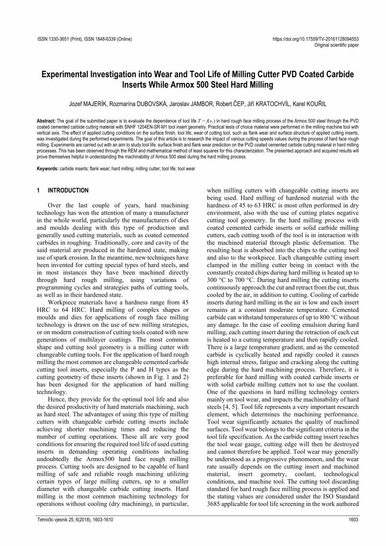
Workpiece material: Armox 500 steel (clamping method is shown in Fig. 1), with the dimensions of 20 × 160 × 500 mm, Rockwell hardness HRC = 48 to 52.
Chemical composition: 0.29 to 0.32% C; 1.20% Mn; 0.40% Si; 1.0% Cr; 1.80% Ni; 0.80% Mo; 0.005% B; 0.005% P; 0.015% S. It was measured by spectral analysis using the Spectrolab JrCCD type of measuring device.
Cutting tool: milling cutter PN222460.12 dia. 50 mm with the geometry z = 4; χr = 75°; γo = −7°; λS = − 4°; α = 7° (NAREX).
Jozef MAJERÍK et al.: Experimental Investigation into Wear and Tool Life of Milling Cutter PVD Coated Carbide Inserts While Armox 500 Steel Hard Milling
1606 Technical Gazette 25, 6(2018), 1603-1610
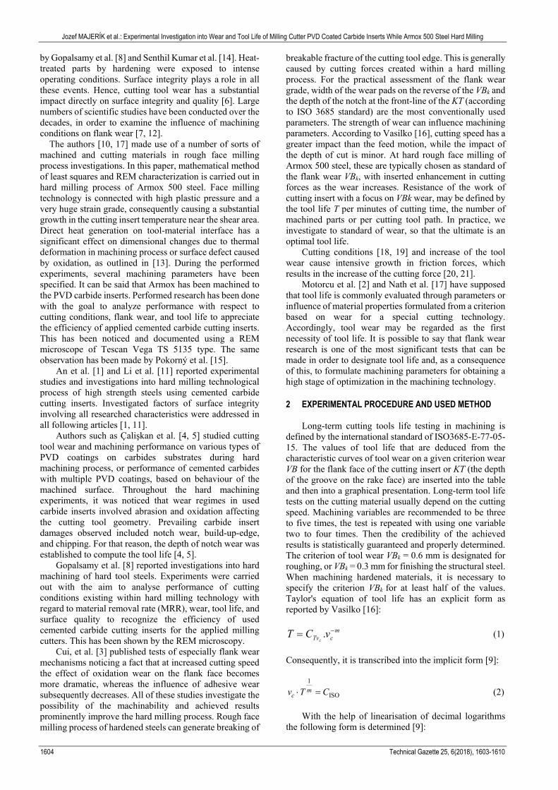
Cutting material: 8230 cemented carbide grade, P30 type, cutting insert geometry SNHF 1204EN-SR-M1.
PVD coating: DORMERPRAMET nano AlTiCN+TiN layered gradient system consisting of a layer with a continuous change of composition (Fig. 2) with plastic hardness Hupl = 38 GPa, thickness = 2 to 3 μm, Ra = 0.1 to 0.2 μm, thermal stability T > 900 °C.
Figure 1 Clamping method and control settings
Figure 2 An overview of rough face hard milling process
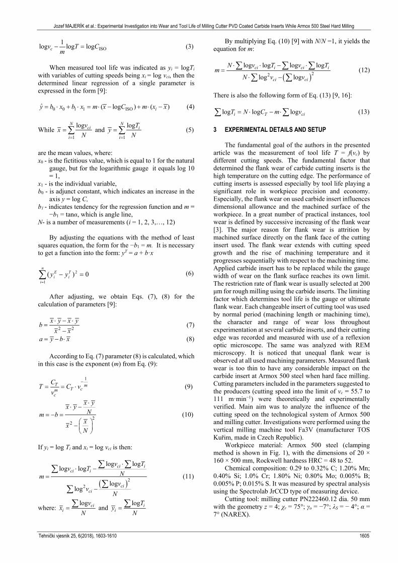
Figure 3 REM image of the flank wear appearance (250×), cutting speed vc =
55.7 m·min−1
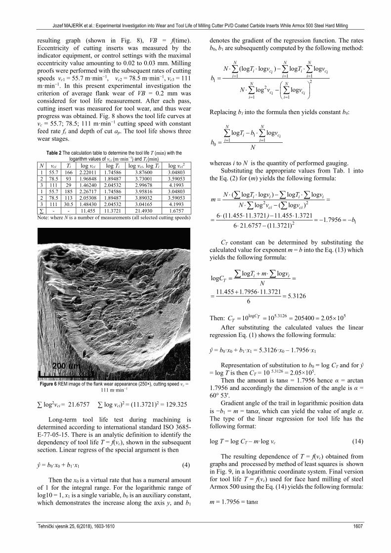
REM images of surface morphology of worn PVD coated cutting carbide inserts (flank edge) before milling are shown in Figs. 3 to 7.
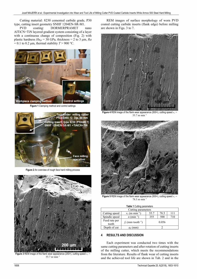
Figure 4 REM image of the flank wear appearance (500×), cutting speed vc = 55.7 m·min−1
Figure 5 REM image of the flank wear appearance (500×), cutting speed vc =
78.5 m·min−1
Table 1 Cutting parameters Cutting parameters
Cutting speed vc (m·min−1) 55.7 78.5 111 Spindle speed n (min−1) 355 500 710 Feed rate per
tooth fz (mm·tooth−1) 0.056
Depth of cut ap (mm) 2 4 RESULTS AND DISCUSSION
Each experiment was conducted two times with the
same cutting parameters and after rotation of cutting inserts of the milling cutter, which meets the recommendations from the literature. Results of flank wear of cutting inserts and the achieved tool life are shown in Tab. 2 and in the
Jozef MAJERÍK et al.: Experimental Investigation into Wear and Tool Life of Milling Cutter PVD Coated Carbide Inserts While Armox 500 Steel Hard Milling
Tehnički vjesnik 25, 6(2018), 1603-1610 1607
resulting graph (shown in Fig. 8), VB = f(time). Eccentricity of cutting inserts was measured by the indicator equipment, or control settings with the maximal eccentricity value amounting to 0.02 to 0.03 mm. Milling proofs were performed with the subsequent rates of cutting speeds vc1 = 55.7 m·min−1, vc2 = 78.5 m·min−1, vc3 = 111 m·min−1. In this present experimental investigation the criterion of average flank wear of VB = 0.2 mm was considered for tool life measurement. After each pass, cutting insert was measured for tool wear, and thus wear progress was obtained. Fig. 8 shows the tool life curves at vc = 55.7; 78.5; 111 m·min−1 cutting speed with constant feed rate fz and depth of cut ap. The tool life shows three wear stages.
Table 2 The calculation table to determine the tool life T (min) with the logarithm values of vci (m·min−1) and Ti (min)
N vci Ti log vci log Ti log vci. log Ti log vci2 1 55.7 166 2.22011 1.74586 3.87600 3.04803 2 78.5 93 1.96848 1.89487 3.73001 3.59053 3 111 29 1.46240 2.04532 2.99678 4.1993 1 55.7 185 2.26717 1.74586 3.95816 3.04803 2 78.5 113 2.05308 1.89487 3.89032 3.59053 3 111 30.5 1.48430 2.04532 3.04165 4.1993 ∑ - - 11.455 11.3721 21.4930 1.6757
Note: where N is a number of measurements (all selected cutting speeds)
Figure 6 REM image of the flank wear appearance (250×), cutting speed vc =
111 m·min−1
∑ log2vci = 21.6757 ∑ log vci)2 = (11.3721)2 = 129.325
Long-term tool life test during machining is determined according to international standard ISO 3685-E-77-05-15. There is an analytic definition to identify the dependency of tool life T = f(vc), shown in the subsequent section. Linear regress of the special argument is then ŷ = b0·x0 + b1·x1 (4)
Then the x0 is a virtual rate that has a numeral amount of 1 for the integral range. For the logarithmic range of log10 = 1, x1 is a single variable, b0 is an auxiliary constant, which demonstrates the increase along the axis y, and b1
denotes the gradient of the regression function. The rates b0, b1 are subsequently computed by the following method:
1 1 11 2
2
1 1
(log log ) log log
log log
N N N
i c i ci ii i i
N N
c ci ii i
N T v T vb
N v v
= = =
= =
⋅ ⋅ − ⋅=
⋅ −
∑ ∑ ∑
∑ ∑
Replacing b1 into the formula then yields constant b0:
11 1
0
log logN N
i cii i
T b vb
N= =
− ⋅=∑ ∑
whereas i to N is the quantity of performed gauging.
Substituting the appropriate values from Tab. 1 into the Eq. (2) for (m) yields the following formula:
2 2
12
( log log ) log loglog ( log )
6 (11 455 11 3721 11 455 1 3721 1 79566 21 6757 (11 3721)
i i i i
ci ci
N T v T vm
N v v. . ) . . . b
. .
⋅ ⋅ − ⋅= =
⋅ −
⋅ ⋅ − ⋅= = − = −
⋅ −
∑ ∑ ∑∑ ∑
CT constant can be determined by substituting the
calculated value for exponent m = b into the Eq. (13) which yields the following formula:
log loglog
11 455 1 7956 11 3721 5 31266
i iT
T m vC
N. . . .
+ ⋅= =
+ ⋅= =
∑ ∑
Then: log 5 3126 510 10 205400 2 05 10C .T
TC .= = = = × After substituting the calculated values the linear
regression Eq. (1) shows the following formula: ŷ = b0·x0 + b1·x1 = 5.3126·x0 – 1.7956·x1
Representation of substitution to b0 = log CT and for ŷ = log T is then CT = 10 5.3126 = 2.05×10⁵.
Then the amount is tanα = 1.7956 hence α = arctan 1.7956 and accordingly the dimension of the angle is α = 60° 53'.
Gradient angle of the trail in logarithmic position data is −b1 = m = tanα, which can yield the value of angle α. The type of the linear regression for tool life has the following format: log T = log CT – m·log vc (14)
The resulting dependence of T = f(vc) obtained from graphs and processed by method of least squares is shown in Fig. 9, in a logarithmic coordinate system. Final version for tool life T = f(vc) used for face hard milling of steel Armox 500 using the Eq. (14) yields the following formula: m = 1.7956 = tanα

Jozef MAJERÍK et al.: Experimental Investigation into Wear and Tool Life of Milling Cutter PVD Coated Carbide Inserts While Armox 500 Steel Hard Milling
1608 Technical Gazette 25, 6(2018), 1603-1610
α = arctan 1.7956 = 60.88° = 60° 53'
Then the final resulting dependence has this following formula:
5
1 79562 05 10T
m ,c c
C .Tv v
×= =
Worn cemented carbide inserts flank face appearance
after all performed milling tests is shown in Figs. 3, 4, 5, 6, and 7 as analysed by REM.
Figure 7 REM image of the flank wear appearance (500×), cutting speed vc = 111 m·min−1
Figure 8 Graphical presentation of dependence of tool wear in hard rough
machining of Armox 500 steel with carbide material of SNHF 1204ENSR-M1 cutting geometry: cemented carbide type 8230 DORMERPRAMET to identify
the dependency T = f(vc)
Surface quality of the hard milled surface is contingent mainly on the used machining parameters and it plays a significant role in functionality and fatigue life of the component. All reserved spindle speeds ni, feed velocity rates vfi and machining times to the separate sections were designated through computation. Monitoring of flank wear
was performed in accordance with 17.5 min; 23.5 min; 26 min; 39.5 min; 43.5 min; 54 min; 68.5 min; 85 min; 100 min; 113 min; 155 min and 180 min using cutting speeds vc1; vc2; vc3 with the flank wear measurement. Subsequently, after the lapse of 39.5 min; 43.5 min; 54 min; 68.5 and 75 min. Measured amounts of flank wear VBmax for vc1 = 55.7 m·min−1, vc2 = 78.5 m·min−1, vc3 = 111 m·min−1, with ap = 2.0 mm and fz = 0.056 mm·rev−1 are determined in the authors’ experiment. Graphic reliance of tool wear on the machining time to vc1, vc2, vc3 by the face rough milling of steel Armox 500 with the machining condition depth of cut at ap = 2.0 mm and feed rate per tooth of fz = 0.056 mm·rev−1, with cutting fluid, is shown in Fig. 8. Three steps of all performed gauging relativity of T = f(vc) according to the relevant formula and defines the form of the graph trace as rectilinear within logarithmic position data (as can be seen in Fig. 9).
Values were applied directly from Tab. 2 for implementation. Tool life testing of vcT curve is presented in Fig. 9. At a rough face milling with the cutting speed of vc1 = 55.7 m·min−1 the breaking and chipping of tool nose begins after 180 minutes of milling time. At milling with the cutting speed of vc2 = 78.5 m·min−1 the breaking and chipping of tool nose begins after 100 minutes of machining time. And at milling with the cutting speed of vc3 = 111 m·min−1 tool nose breaking stops after 27 minutes of machining time. Increasing the cutting speed to vc3, the tool life is reduced and tool nose grows less.
Figure 9 Tool life testing of vcT curve while milling of Armox 500
The principal tool wear systems comprise cutting
insert nose breaking and splitting of the flank edge. The experimental test of hard milling at the cutting speed of vc3 was substantially more elaborated for milling. Tool lives smaller than 27 minutes were accomplished. With the cutting insert nose being partly broken due to high cutting forces and stresses, machining factors are degraded at the cutting edge and as a consequence of machined armour plate adherence to damaged flank edge zones the edge builds up.
All these figures present the appearances of worn inserts when the cutting speed reaches the values of vc = 55.7; 78.5 and 111 m·min−1. The high strength of Armox 500 makes it exhibit brittleness to some extent, even at a

Jozef MAJERÍK et al.: Experimental Investigation into Wear and Tool Life of Milling Cutter PVD Coated Carbide Inserts While Armox 500 Steel Hard Milling
Tehnički vjesnik 25, 6(2018), 1603-1610 1609
high temperature. Crater wear is obvious on the tool rake face and is especially present due to the high machining temperature on cutting insert–chip landmark. Tool life depends on optimal geometry of the cutting tool for the specific cutting material. It also depends on the physical parameters such as cutting speed, chip thickness and chip width. In areas of cutting speeds, which have practical significance, it is possible to graphically represent the dependence of tool life directly on the various physical parameters in the logarithmic graph (shown in Fig. 9). The angle between the obtained dependence (Fig. 9) and horizontal axis of the graph (log vc) represents the impact of these physical parameters on tool life. With the increasing size of the angle increases the impact of the main physical argument vc of the tool life T. Mathematical dependence of tool life on the physical parameters can be formulated by the empirical Eq. (7) as reported by Vasilko [16]. Feed rate and depth of cut have an influence on tool life T only to a degree, although the chip thickness and width are affected, and is of general application to all methods of machining. 5 CONCLUSION
This experimental study is focused on the principal dependence between tool wear, tool life, and surface integrity in rough machining of Armox 500steel. The fundamental key records can be resumed as follows: • Cutting speed (as the cutting parameter used) has the
most significant effect on the flank wear (in contrast to the feed rate and depth of cut).
• The obtained records are statistically processed by the rectilinear regression tests using the process of the least squares. The measured and calculated results and values are shown in Tab. 2, and graphic reliance of the flank wear VB (mm) is time-dependent..
• The study of the size and location of the flank wear in worn coated cemented carbide insert was also monitored with the usage of the REM (shown in Figs. 3 to 7). The scanning electron microscope was utilized to evaluate worn cutting inserts, for higher appearance of the worn shape and size of flank wear, and for chipping and tool nose breaking. Reflection Electron Microscopy (REM) analysis has allowed to investigate the flank wear effects that characterise the tool wear in the hard milling of Armox 500 in more details.
• It was noticed that the principal wear methods affecting all worn cutting inserts are abrasion and oxidation. Dominant cutting insert disturbances include notch wear, tool nose breaking, and chipping. Due to the high cutting temperature within the cutting area during the machining process, thermic split also occurs in the worn zone.
• Detected substrate material extended during the cutting process, and this involved exceeding the machining temperature. It was engrained by Substantial test of the worn surface demonstrated a high sticking of the workpiece sample to the cutting tool face due to the temperature access.
As for the used cemented carbide cutting material with
AlTiCN+TiN PVD coating, the carbide insert wear started with the delamination of the coat onto the flank zone in
addition to abrasion, adhesion oxidation (all are shown in Figs. 3 to 7). The composition of cutting edge of carbide inserts changed entirely. Due to the high temperature inside the machining area within the hard face milling process, thermal cracks also exist on the worn area. As to the defined cutting conditions, the biggest effect has been exerted by cutting speed vc, less feed rate f, and the least depth of cut ap. What yet needs to be studied more are dependences of tool life T = f(fz) or T = f(ap), and the grade of the noticed flank wear. This opens up possibilities for further research into this matter. Further investigations and experiments into the dependence of T = f(fz, ap) on different cutting conditions relating to the flank wear response and surface integrity will be performed. Acknowledgements
This work was supported by the Slovak Research and
Development Agency under the contract No. APVV-15-0710. It also includes support and cooperation with the University of Defence in Brno, Department of mechanical engineering.
6 REFERENCES [1] An, Q., Wang, C., Xu, J., Liu, P., & Chen, M. (2014).
Experimental investigation on hard milling of high strength steel using PVD-AlTiN coated cemented carbide tool. International Journal of Refractory Metals and Hard Materials, 43, 94-101.
https://doi.org/10.1016/j.ijrmhm.2013.11.007 [2] Motorcu, A. R., Kuş, A., Arslan, R., Tekin, I., & Ezentaş, R.
(2013). Evaluation of tool life - tool wear in milling of inconel 718 super alloy and the investigation of effects of cutting parameters on surface roughness with Taguchi method. Tehnički vjesnik, 20(5), 765-774.
[3] Cui, X., Zhao, J., & Tian, X. (1990). Tool wear in high-speed face milling of AISI H13 steel. Journal of Engineering Manufacture, 226(2), 5-21.
[4] Çaliskan, H., Kurbanoǧlu, C., Panjan, P., Čekada, P., & Kramar, D. (2013). Wear behaviour and cutting performance of nanostructured hard coatings on cemented carbide cutting tools in hard milling. Tribology International, 62, 215-222.
https://doi.org/10.1016/j.triboint.2013.02.035 [5] Çaliskan, H., Kurbanoǧlu, C., Panjan, P., & Kramar, D.
(2013). Investigation of the performance of carbide cutting tools with hard coatings in hard milling based on the response surface methodology. International Journal of Advanced Manufacturing Technology, 66, 883-893.
https://doi.org/10.1007/s00170-012-4374-y [6] Denkena, B., Köhler, J., & Bergmann, B. (2015).
Development of cutting edge geometries for hard milling operations. CIRP Journal of Manufacturing Science and Technology, 8, 43-52. https://doi.org/10.1016/j.cirpj.2014.10.002
[7] Dubovská, R., Majerík, J., Čep, R., & Kouřil, K. (2016). Investigating the influence of cutting speed on the tool life of a cutting insert while cutting DIN 1.4301 steel. Materiali in Tehnologije, 50(3), 439-445.
https://doi.org/10.17222/mit.2015.036 [8] Gopalsamy, B. M., Mondal, B., Ghosh, S., Arntz, K., &
Klocke, F. (2009). Investigations on hard machining of Impax Hi Hardtoolsteel. International Journal of Material Forming, 2(3), 145-165. https://doi.org/10.1007/s12289-009-0400-5
[9] Kundor, N. F., Awang, N. W., & Berahim, N. (2016). Tool wear and surface roughness in machining AISI D2 tool steel. Indian Journal of Science and Technology, 9(18), 20-25.
Jozef MAJERÍK et al.: Experimental Investigation into Wear and Tool Life of Milling Cutter PVD Coated Carbide Inserts While Armox 500 Steel Hard Milling
1610 Technical Gazette 25, 6(2018), 1603-1610
https://doi.org/10.17485/ijst/2016/v9i18/88731 [10] Čep, R., Janásek, A., Čepová, L., Petrů, J., Hlavatý, I., Car,
Z., & Hatala, M. (2013). Experimental testing of changeable cutting inserts cutting ability. Tehnički vjesnik, 20(1), 21-26.
[11] Li, W., Guo, Y., & Guo, C. (2013). Superior surface integrity by sustainable dry hard milling and impact on fatigue. CIRP Annals - Manufacturing Technology, 62(1), 567-570. https://doi.org/10.1016/j.cirp.2013.03.024
[12] Lajis, M. A., Karim, A. N. M., Arim, A. K. M. N., Hafiz, A. M. K., & Turnad, L. G. (2008). Prediction of tool life in end milling of hardened steel AISI D2. European Journal of Scientific Research, 21(4), 592-602.
[13] Prakash, M., Shekhar, S., Moon, A. P., & Mondal, K. (2015). Effect on machining configuration on the corrosion of mild steel. Journal of Materials Processing Technology, 219, 70-83. https://doi.org/10.1016/j.jmatprotec.2014.11.044
[14] Senthil Kumar, A., Raja Durai, A., & Sornakumar, T. (2006). The effect of tool wear on tool life of alumina-based ceramic cutting tools while machining hardened martensitic stainless steel. Journal of Materials Processing Technology, 173(2), 151-156. https://doi.org/10.1016/j.jmatprotec.2005.11.012
[15] Pokorný, Z., Hrubý, V., & Studený, Z. (2016). Effect of nitrogen on surface morphology of layers. Kovové Materiály, 54(2), 119-124. https://doi.org/10.4149/km_2016_2_119
[16] Vasilko, K. (2012). Effective examination for obtaining relation T = f(vc). Manufacturing Technology, 12(13), 277-281.
[17] Nath, C., Brooks, Z., & Kurfess, T. R. (2015). Machinability study and process optimization in face milling of some super alloys with indexable copy face mill inserts. Journal of Manufacturing Processes, 20, 88-97. https://doi.org/10.1016/j.jmapro.2015.09.006
[18] Krolczyk, G., Legutko, S., & Raos, P. (2013). Cutting wedge wear examination during turning of duplex stainless steel. Tehnički vjesnik, 20(3), 413-418.
[19] Maruda, R., Legutko, S., Krolczyk, G., Hloch, S., & Michalski, M. (2015). Influence of Active Additives on the Formation of Selected Indicators of the Condition of the Z10CrNi18-8 Stainless Steel Surface Layer in MQCL Conditions. International Journal of Surface Science and Engineering, 9(5), 452-465. https://doi.org/10.1504/IJSURFSE.2015.072069
[20] Twardowski, P., Legutko, S., Krolczyk, G., & Hloch, S. (2015). Investigation of wear and tool life of coated carbide and cubic boron nitride cutting tools in high speed milling. Advances in Mechanical Engineering, 7(6), 1-9. https://doi.org/10.1177/1687814015590216
[21] Nieslony, P., Cichosz, P., Krolczyk, G., Legutko, S., Smyczek, D., & Kolodziej, M. (2016). Experimental studies of the cutting force and surface morphology of explosively clad Ti –steel plates. Measurement, 78, 129-137. https://doi.org/10.1016/j.measurement.2015.10.005
Contact information:
Jozef MAJERÍK, Assoc. Prof., PhD, MSc Alexander Dubcek University of Trencin Faculty of Special Technology Department of Engineering Pri Parku 19, 911 05, Trenčín, Slovak Republic E-mail: [email protected]
Rozmarína DUBOVSKÁ, Prof., PhD, MSc UHK-University of Hradec Kralove Faculty of Education Department of technical subjects Rokitanskeho 62, 500 03, Hradec Kralove, Czech Republic E-mail: [email protected]
Jaroslav JAMBOR, PhD, MSc Alexander Dubcek University of Trencin Studentska 1, 911 50, Trenčín, Slovak Republic E-mail: [email protected]
Robert ČEP, Prof., PhD, MSc VŠB-Technical University of Ostrava Faculty of Mechanical Engineering Department of Machining, Assembly and Engineering Metrology 17. listopadu 15, 708 33, Ostrava, Czech Republic E-mail: [email protected]
Jiří KRATOCHVÍL, PhD, MSc VŠB-Technical University of Ostrava Faculty of Mechanical Engineering Department of Machining, Assembly and Engineering Metrology 17. listopadu 15, 708 33, Ostrava, Czech Republic E-mail: [email protected]
Karel KOUŘIL, PhD, MSc Brno University of Technology Faculty of Mechanical Engineering Institute of Manufacturing Technology Technická 2896/2, 616 69 Brno, Czech Republic E-mail: [email protected]