experimental image processing supported particles nm)€¦ · experimental image processing of...
TRANSCRIPT
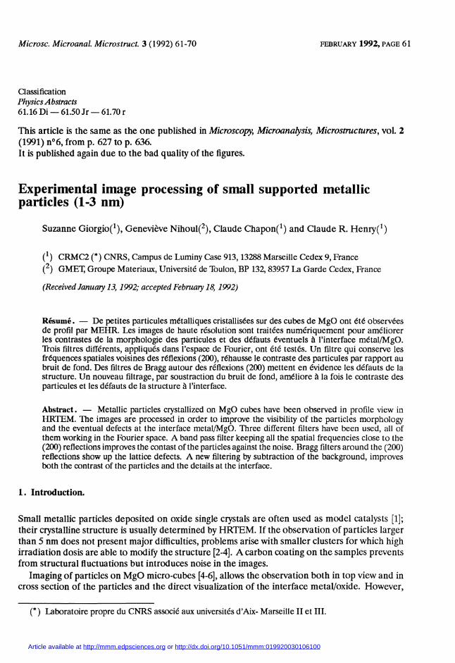
61-
Experimental image processing of small supported metallicparticles (1-3 nm)
Suzanne Giorgio(1), Geneviève Nihoul(2), Claude Chapon(1) and Claude R. Henry(1)
(1) CRMC2 (*) CNRS, Campus de Luminy Case 913, 13288 Marseille Cedex 9, France(2) GMET, Groupe Materiaux, Université de Toulon, BP 132, 83957 La Garde Cedex, France
(Received January 13, 1992; accepted February 18, 1992)
Résume. 2014 De petites particules métalliques cristallisées sur des cubes de MgO ont été observéesde profil par MEHR. Les images de haute résolution sont traitées numériquement pour améliorerles contrastes de la morphologie des particules et des défauts éventuels à l’interface métal/MgO.Trois filtres différents, appliqués dans l’espace de Fourier, ont été testés. Un filtre qui conserve lesfréquences spatiales voisines des réflexions (200), réhausse le contraste des particules par rapport aubruit de fond. Des filtres de Bragg autour des réflexions (200) mettent en évidence les défauts de lastructure. Un nouveau filtrage, par soustraction du bruit de fond, améliore à la fois le contraste desparticules et les défauts de la structure à l’interface.
Abstract. 2014 Metallic particles crystallized on MgO cubes have been observed in profile view inHRTEM. The images are processed in order to improve the visibility of the particles morphologyand the eventual defects at the interface metal/MgO. Three different filters have been used, all ofthem working in the Fourier space. A band pass filter keeping all the spatial frequencies close to the(200) reflections improves the contast of the particles against the noise. Bragg filters around the (200)reflections show up the lattice defects. A new filtering by subtraction of the background, improvesboth the contrast of the particles and the details at the interface.
Microsc. Microanal. Microstruct. 3 (1992)
Classification
Physics Abstracts61.16 Di - 61.50 Jr - 61.70 r
FEBRUARY 1992, PAGE 61
This article is the same as the one published in Microscopy, Microanalysis, Microstructures, vol. 2(1991) n°6, from p. 627 to p. 636.It is published again due to the bad quality of the figures.
1. Introduction.
Small metallic particles deposited on oxide single crystals are often used as model catalysts [1];their crystalline structure is usually determined by HRTEM. If the observation of particles largerthan 5 nm does not present major difficulties, problems arise with smaller clusters for which highirradiation dosis are able to modify the structure [2-4]. A carbon coating on the samples preventsfrom structural fluctuations but introduces noise in the images.
Imaging of particles on MgO micro-cubes [4-6], allows the observation both in top view and incross section of the particles and the direct visualization of the interface metal/oxide. However,
Article available at http://mmm.edpsciences.org or http://dx.doi.org/10.1051/mmm:019920030106100

62
the contrast of the particles and of the interface is buried in the Fresnel fringes at the edge of thesupport.
Image processing of the HRTEM images is used in order to extract both the morphology of thesmall particles seen in profile view (limit between the crystalline material and the coating) andthe defects at the interface metal/oxide. A large variety of common image processings are com-mercialized, most of them working in real space; for periodic objects [7-9], it is more convenientto apply filters in the Fourier space and to obtain processed image by inverse Fourier transform.Image processing of HRTEM pictures with non periodic features has been investigated [10] inthe case of metallic interfaces and boundaries. Non periodic objects introduce continuous com-ponents around the main spots, which have to be kept. Specific filters in the Fourier space werealready tested according to their ability to preserve the non periodic details in the image (de-fects,...). Tbvo types of filters are often selected: a circular band pass filter in the Fourier space,preserving the interesting frequencies, removes some of the noise and the Fresnel fringes [11],while a Bragg filter, must be chosen if one is interested in particular details in the lattice.
Another type of Fourier space processing has been proposed [12], where all the points inten-sities lower than a given threshold are reduced to zero. This type of filter does not introduceas many ghost lattices as do the Bragg filters but it can suppress the non periodic details whichcorrespond to an often weak diffuse area in the Fourier transform.
Finally, in the case of small metal particles, the single value decomposition method [13] wasapplied: though it only enhances one direction of fringes, the morphology of the particle wasbetter seen.
In this paper, we want to compare different manners of processing HRTEM images of smallAu and Pd particles, seen in profile view on MgO cubes.
2. Experimental images.
2.1 SAMPLE PREPARATION AND OBSERVATION IN HRTEM. - A Mg ribbon, burnt in pure oxy-gen and nitrogen in a vacuum chamber, produced MgO cubes collected on a microscope gridcovered with a carbon film [5]. The grid was brought in front of a Knudsen cell for the vacuummetal deposition. Then, a carbon film of average thickness 3 nm, was deposited on the sample toavoid further contamination and to stabilize the particles in the electron beam.
The samples were observed with a Jeol 4000 EX working at 400 kV Figure 1 shows the generalview of microcubes covered with small Au particles «5 nm) sitting on their top ans side surfaces.Here, the MgO cubes are seen along their 100> axis so that the (200) planes are imaged inHRTEM.
2.2 PROCESSING OF THE HRTEM IMAGES: RING AND BRAGG FILTERS. - For the small particleshaving a low contrast, as in figures 2a, b, c, the morphology has to be precised by filtering thenoise arising from the carbon films. The high resolution images were digitized with 256 greylevels and 256 x 256 pixels with a sampling of 1 pixel for 0.02 nm at the level of the object, so thattwo neighbouring lattice fringes are separated by about 10 pixels. Their Fourier transforms (FT)(Figs. 3a, b, c) show the central beam and the four strongest (200) reflections. All the reflectionsare elongated in the direction normal to the interface. The (200) reflections are separated fromthe central beam by 21 pixels; one pixel in the Fourier space represents then 0.2 nm-An example of the radial distribution in the FT is given in figure 3d. There, the intensity be-
tween the zero spacial frequency and the (200) reflections does not fall to zero and contains oscil-lations due to the presence of the amorphous background. Also, the peak corresponding to the(200) reflections is enlarged.

63
Fig. 1. - Overview of MgO cubes with particles on their surface and on their edges.
Fig. 2. - a) Small palladium particle (1 nm) seen in profile view, b) gold particle (1.6 nm), c) gold particle(3.6 nm).
A ring filter centered on the zero frequency (band pass filter in the Fourier space), having asits mean radius the (200) reflections frequency was applied; several widths were tried. In orderto avoid the artefacts produced by discontinuous edges, a filter with soft edges was chosen, firstwith a Gaussian shape, then with a shape described by equation (1), giving a flatter maximum andsharp edges :

64
Fig. 3. - a,b,c, Fourier Transforms of the images (Figs. 2a,b,c). d) Logarithm of the radial distribution ofthe Fourier transform (3b).
where g is the mean radius of the filter (go = g(200)) and 03C3 is a parameter defining the averagewidth of the ring filter.
Figures 4a, b, c give processed images of figures 2a, b, c with 03C3 = 3, 4, 5, 6 pixels correspondingto o- = 0.7, 0.9, 1.1 and 1.3 nm-l respectively in the Fourier space.
The processed images of the 1-2 nm sized particles (Figs. 2a, 2b) seem to change between thesmallest values of cr (=3) and 03C3 = 4, 5, 6. Indeed, the top of the particles is difficult to localize foro- = 3. The contrast of the particles compared to the background decreases for increasing valuesof cr while the non periodic details (the morphology, the eventual distorsions in the image at theinterface) appear more clearly. Then, ghost fringes parallel to the interface and to the upper edgeare found for the lowest values of cr. In fact, for the smallest particles (Fig. 2a) having N = 5cells along the interface, the enlargement 1/(N * a) of the reflections in the Fourier space is 0.95nm-1, so that the non periodic details might be completely lost by the filters with cr 4.3. Onthe opposite, in the image of the large particles (Fig. 2c) with 17 cells and a stronger contrast, thevisualization of the morphology is not significantly improved, however for all particles, the detailshidden in the Fresnel fringe now appear with the four values of cr.
In order to remove the artefacts in the FT, introduced by a limited square digitizing [14] (streaksparallel to the window edges), the digitized image was multiplied by a circular mask C with softedges. Then, in the FT (5b), of image 2b which has been multiplied by the mask C (5a), the

65
Fig. 4. - a, b, c Processed images from figures 2a, b, c by noise filtering with ring filters with increasingwidths (03C3 = 3, 4, 5, 6 respectively). X indicates the average radius of the ring.

66
Fig. 4. - (continued)
Fig. 5. - a) Image 2b masked with the ring filter. b) Fourier transform of Sa.
lengthening of the spots due to the square window are less pronounced (compare 5b to 3b).Then, the eventual ghost lattices found in figures 4b near the edges deseappear from the back-
ground (see Figs. 6a, b, c, d).The same particles have been processed by Bragg filters with circula r holes centered on two or
four (200) reflections. The profile of each hole with soft edges is given by equation (2):
where g is a vector of the Fourier transform of the image, and go is a (200) vector.

67
Fig. 6. - a, b, c, d Processed images from 2b with the ring mask (5a), applied on the real image, and withring filter applied on the Fourier transform, (03C3 = 3, 4, 5, 6, respectively).
Figures 7a, b, c show the particle from figure 2b processed with these Bragg filters for increasingvalues of (1’. Ghost lattices are created in the amorphous area, as could be expected as the radialdistribution of the FT (Fig.3d) showed a high contribution of the amorphous background, aroundthe (200) spatial frequency.
Defects are shown by processing with only two Bragg filters corresponding to two opposite(200) reflections (Figs. 7a, b, c). For increasing widths of the disc (03C32 = 4, 16, 25), imperfectionsin the lattice appear. Some strong distortions can be sometimes seen in the crystalline area, butalso in the ghost lattices in the background. In fact, the amorphous background is able to givediscontinuities in the frequencies, then artefacts are seen in the backgound of the processed image.As the particles and the MgO are enclosed between two carbon layers, the same distortions may besuperimposed on the crystal. So, this type of treatment must be used very carefully in the case ofa mixture of amorphous and crystalline superimposed material. However, it is the most powerfulmethod to enhance the defects in a crystalline area.
2.3 PROCESSING BY SUBTRACTION OF THE BACKGROUND. - When looking at the radial distri-bution of the FT, it is tempting to try to subtract the background due to the amorphous part fromthe whole signal in order to only retain the crystalline contribution. The background for the spa-tial frequencies around the (200) refiections can be calculated by averaging the values for pixelscorresponding to the same spatial frequencies but far from the (200) spots.Two circles, centered on the central beam and including the (200) reflections were drawn. This
ring was separated in three parts, the middle including the reflections, the inner and the outerones were used to calculate the intensities of the background Il and 13. The background in themiddle ring 12 was given the average values (I1 + 13) /2. Then, the points located outside the fourcircles were given the intensity zero and the intensity of each point in the circles was compared to12. If the intensity was smaller than 12, the point was taken as background and the intensity was

68
Fig. 7. - a, b, c, Processed images from figure 2b with the Bragg filter (one pair and two pairs of holes) withincreasing values of 03C3 (03C3 = 4, 16, 25). X and Y are the coordinates of the centers of the discs, SIG2 is thesquare of the filter width 03C3.
put to zero. In the other case, it was considered as part of a reflection and two processings weretried:
i) the intensity of the point was unchanged, (procedure A).ii) the average intensity of the background 12 was subtracted from the intensity of the point, (pro-cedure B).
In both procedures, A and B, the phase was kept.This method is more detailed in the theoretical part, [15].The results of this processing on the images shown in figures 2a, b, c, are shown in figure 8, for
four different mask widths (03C3 = 6, 8, 10, 12).The best images are obtained for the largest widths values (bottom right), which show that we
69
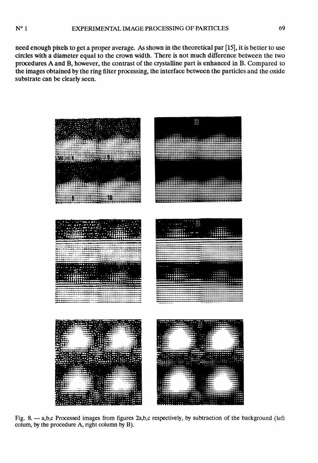
need enough pixels to get a proper average. As shown in the theoretical par [15], it is better to usecircles with a diameter equal to the crown width. There is not much difference between the twoprocedures A and B, however, the contrast of the crystalline part is enhanced in B. Compared tothe images obtained by the ring filter processing, the interface between the particles and the oxidesubstrate can be clearly seen.
Fig. 8. - a,b,c Processed images from figures 2a,b,c respectively, by subtraction of the background (leftcolum, by the procedure A, right column by B).

70
3. Dicussion.
The application of three different image processings, working in the Fourier space, have showninteresting détails in HRTEM profile images of supported small metallic particles.- The band-pass filter improves the particles morphology by subtraction of the frequencies
different from the ones around the (200) reflections. This type of mask also extracts the details ofthe interface, normally hidden in the Fresnel fringes.- The Bragg filter enhances the defects and distortions at the interface, but introduces ghost
lattices in the background. This type of filter is difficult to be used to process images where a crys-talline area and an amorphous background are superimposed. However, it is a powerful treatmentto underline the structural defects in crystals.
- The subtraction of the amorphous background gives results comparable to the band-pass filteras it improves the morphology of the particles and the details at the interface but it enhances morethe contrast between the crystalline and amorphous areas.
In order to keep the non periodic details, one must take into account that the particles have alimited size, so that their reflections are enlarged in the FT and the width of the masks has to becalculated according to each particle size.
References
[1] HENRY C.R., CHAPON C. and DURIEZ C., Z. Phys. D 19 (1991) 347.[2] IIJIMA S. and ICHIHASHI T, Phys. Rev. Lett. 56 (1986) 616.[3J AJAYAN P.M. and MARKS L.D., Phys. Rev. Lett. 63 (1989) 279.[4] GIORGIO S., HENRY C.R., CHAPON C., NIHOUL G., PENISSON J.M., Ultramicroscopy 38 (1991) 1.[5] GIORGIO S., HENRY C.R., CHAPON C., PENISSON J.M., J. Cryst. Growth 100 (1990) 254.[6] GIORGIO S., CHAPON C., HENRY C.R., NIHOUL G., PENISSON J.M., Philos. Mag. A 64 (1991) 87.[7] HAWKES P.W., Optik 40 (1974) 539.[8] SAXTON W.O., Computer Techniques for image processing in electron microscopy (New York, Aca-
demic press, 1978);SAXTON W.O., Computer processing of electron microscope images, P.W. Hawkes Ed. (Springer Verlag
Berlin, New York, 1980) p. 15.[9] HAWKES P.W, Computer graphics and image processing 18 (1982) 58.
[10] de JONG A.F., COENE W. and VAN DYCK D., Ultramicroscopy 27 (1989) 53.[11] SAXTON W.O., in Proceeding of the 44th annual meeting of the electron microscopy Society of America,
G.W. Bailey Ed. (San Francisco Press, 1986) pp. 526-529.[12] PRADÈRE P. and THOMAS E.L., Ultramicroscopy 32 (1990) 149.[13] ARTAL P., AVALOS BORJA M., SORIA F., POPPA H., HEINEMANN K., Ultramicroscopy 30 (1989) 405.[14] TOMITA M., HASHIMOTO H., IKUTA T, ENDOH H. and YOKOTA Y., Ultramicroscopy 16 (1985) 9.[15] NIHOUL G., Microsc. Microanal. Microstruct. 2 (1991) 637.