experiment of 348 mbps downlink from 50-kg class satellite · conclusion we developed the high...
TRANSCRIPT
Experiment of 348 Mbps downlink from 50-kg class satellite
10th IAA Symposium on Small Satellites for Earth Observation
April 20 - 24, 2015 Berlin, Germany
Tomoya Fukami, The University of Tokyo
fukami.tomoya at ac.jaxa.jp
Hiromi Watanabe, Hirobumi Saito , Atsushi Tomiki
Takahide Mizuno, Naohiko Iwakiri, Osamu Shigeta
Hitoshi Nunomura, Kaname Kojima and Takahiro Shinke
IAA-B10-1302
Background
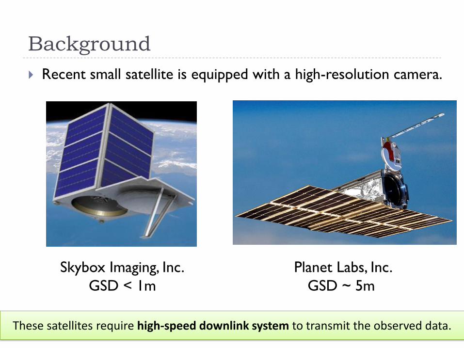
Recent small satellite is equipped with a high-resolution camera.
Skybox Imaging, Inc.
GSD < 1m
Planet Labs, Inc.
GSD ~ 5m
2 These satellites require high-speed downlink system to transmit the observed data.
Background
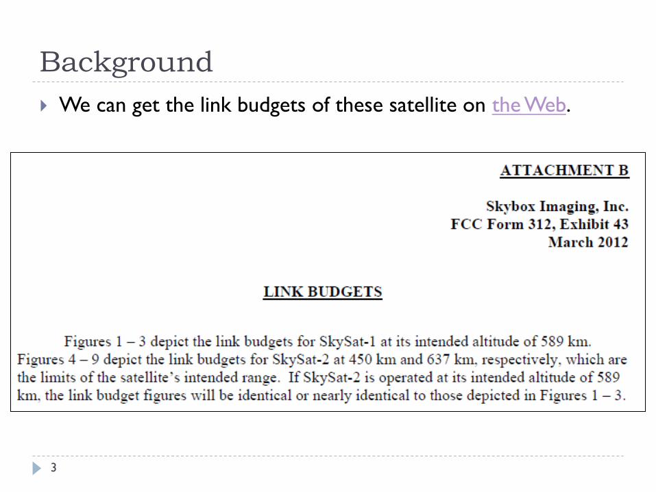
We can get the link budgets of these satellite on the Web.
3
Downlink system of existing satellite
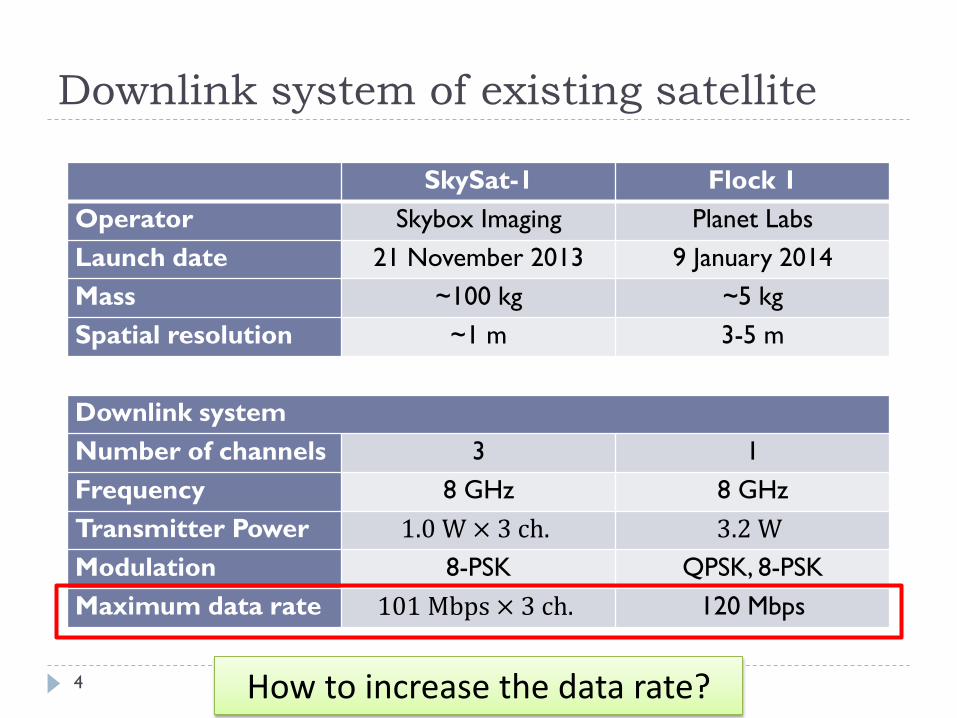
SkySat-1 Flock 1
Operator Skybox Imaging Planet Labs
Launch date 21 November 2013 9 January 2014
Mass ~100 kg ~5 kg
Spatial resolution ~1 m 3-5 m
Downlink system
Number of channels 3 1
Frequency 8 GHz 8 GHz
Transmitter Power 1.0 W × 3 ch. 3.2 W
Modulation 8-PSK QPSK, 8-PSK
Maximum data rate 101 Mbps × 3 ch. 120 Mbps
How to increase the data rate? 4
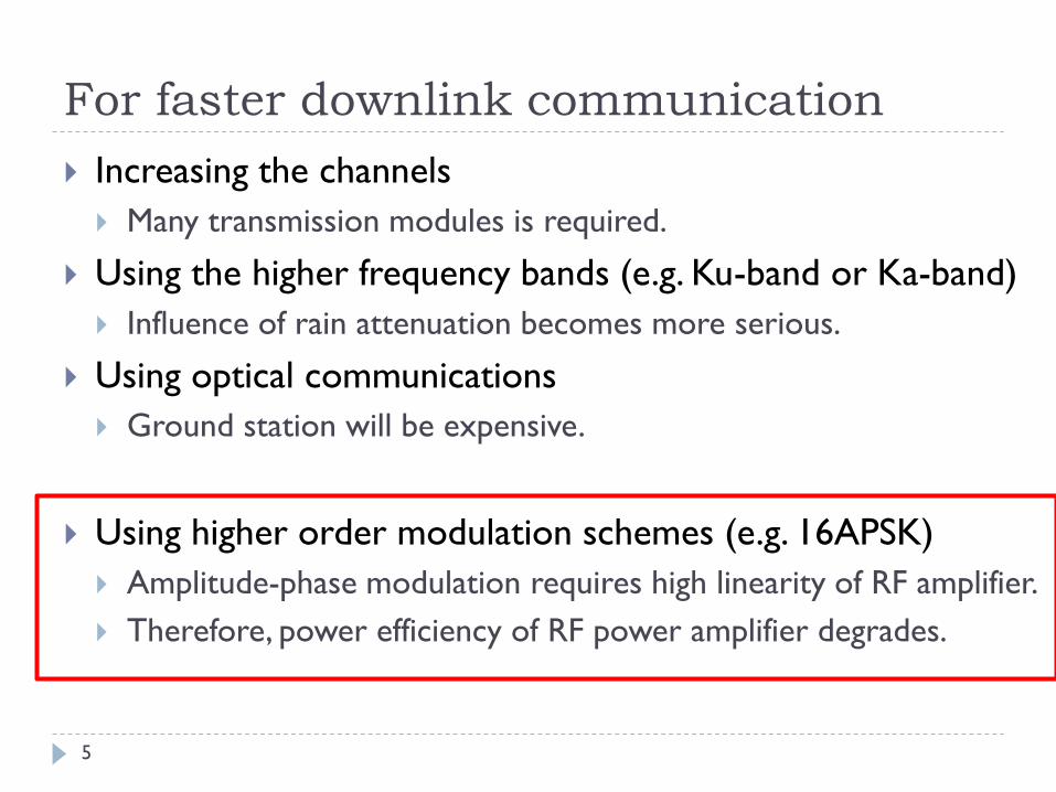
For faster downlink communication
Increasing the channels
Many transmission modules is required.
Using the higher frequency bands (e.g. Ku-band or Ka-band)
Influence of rain attenuation becomes more serious.
Using optical communications
Ground station will be expensive.
Using higher order modulation schemes (e.g. 16APSK)
Amplitude-phase modulation requires high linearity of RF amplifier.
Therefore, power efficiency of RF power amplifier degrades.
5

The purpose of our research
High-Speed Downlink System
using Amplitude-Phase Modulation for Small Satellite
Goal
50 kg-class satellite @ 600 km orbit
Power consumption < 25 W
Small ground antenna < 4m
Data rate > 300 Mbps
Low total system cost
348 Mbps
6

16QAM Downlink with Nonlinear Amplifier
Why the amplitude-phase modulation is difficult?
Ref. SSC13-I-8 7
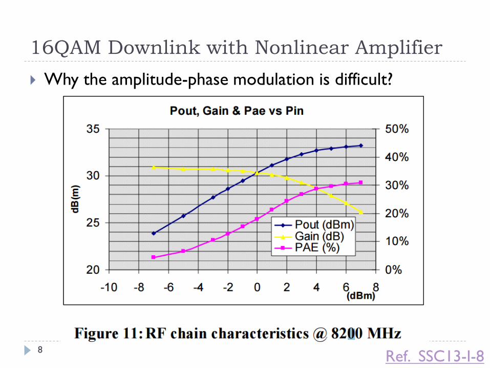
16QAM Downlink with Nonlinear Amplifier
Why the amplitude-phase modulation is difficult?
Ref. SSC13-I-8 8
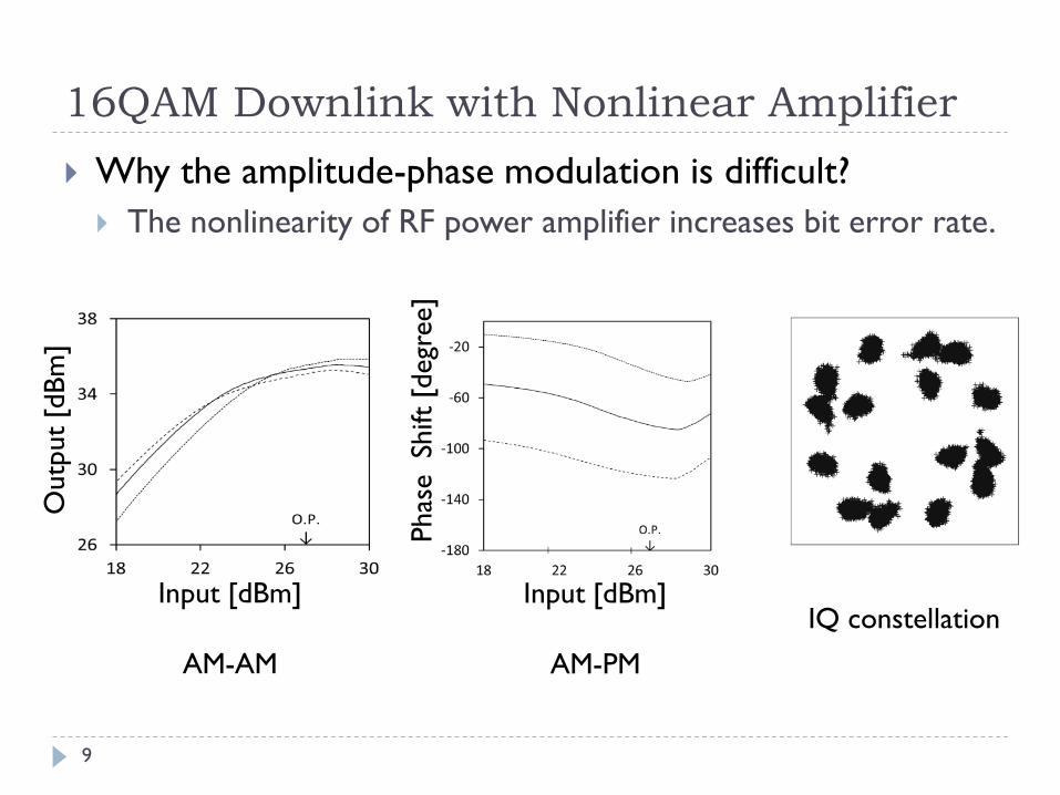
16QAM Downlink with Nonlinear Amplifier
Why the amplitude-phase modulation is difficult?
The nonlinearity of RF power amplifier increases bit error rate.
Input [dBm]
AM-PM
Phas
e Sh
ift
[degr
ee]
Outp
ut
[dB
m]
Input [dBm]
AM-AM
IQ constellation
9

X Band Power Amplifiers
We developed a new GaN-HEMT amplifier.
Newly Developed 2W GaN HEMT AB Class
3cm
Amplifier GaAs AB GaN AB GaN F
Maximum Power 38dBm 37dBm 36dBm
Maximum Gain 10dB 11dB 12dB
Maximum PAE 37% 46% 60%
PAE at 3dB OBO 23% 36% 38%
Maximum Phase Shift 10° -2° -34°
10
11
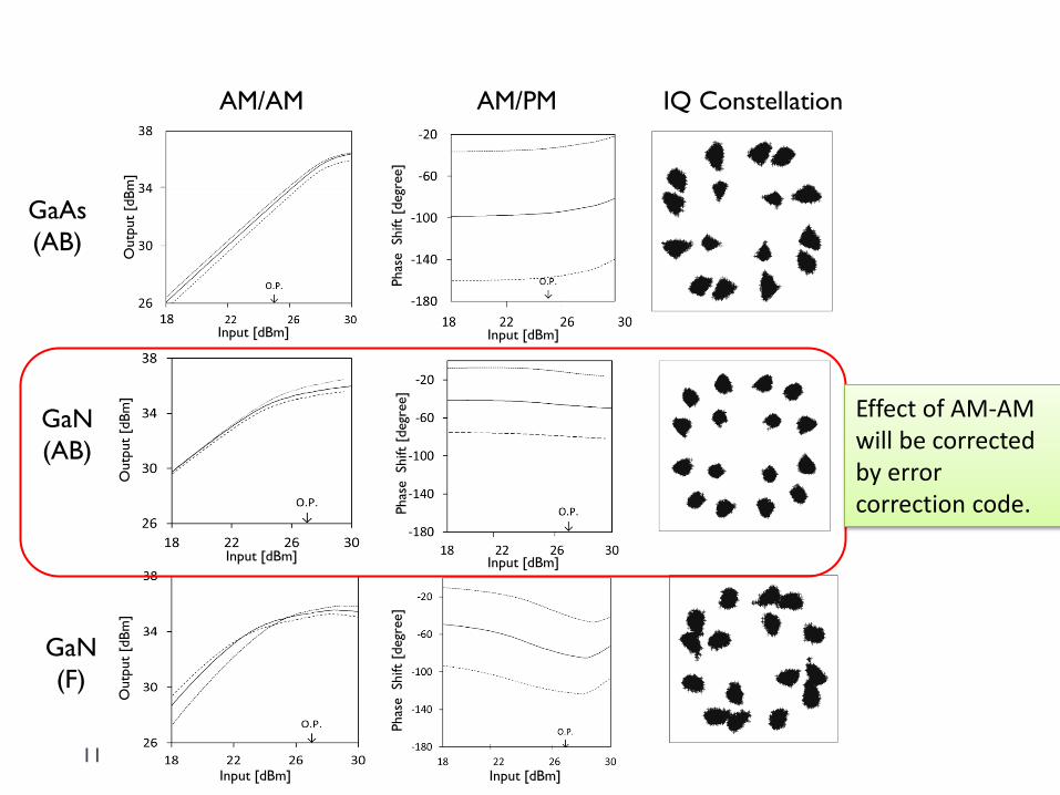
AM/AM AM/PM IQ Constellation
GaAs
(AB)
GaN
(AB)
GaN
(F)
Phas
e Sh
ift
[degr
ee]
Outp
ut
[dB
m]
Input [dBm]
Input [dBm]
Phas
e Sh
ift
[degr
ee]
Outp
ut
[dB
m]
Input [dBm]
Input [dBm]
Phas
e Sh
ift
[degr
ee]
Outp
ut
[dB
m]
Input [dBm] Input [dBm]
Effect of AM-AM will be corrected by error correction code.

Onboard Transmitter Specifications of onboard transmitter
Frequency band 8160 ± 60 MHz
RF output power 2 W
Symbol rate 100 Msps
Modulation schemes QPSK, 16QAM,
8PSK, 16APSK, 32APSK,
64APSK, 64QAM
Data rate (user) 72 to 540 Mbps
Error correction
code
SCCC based on CCSDS
131.2-B-1
Data input interface LVDS
DC power 28 V, 22 W
Volume 12 × 10 × 7.3 cm
Weight 1330 g
Operating
temperature
-20 to +50 °C
Radiation test 20 kRad
Flight model
RF block
Baseband block
12

Error Correction and Modulations
CCSDS 131.2-B-1
Blue book was published in 2012.
QPSK to 64APSK
DVB-S2 supports up to 32APSK.
Turbo code
Serial Concatenated
Convolutional Code (SCCC)
13

Simulation Results of Frame Error Rate
Es/N0 [dB]
Fra
me E
rror
Rat
e
Ref. ESA 14 The data rate can be changed based on link condition.
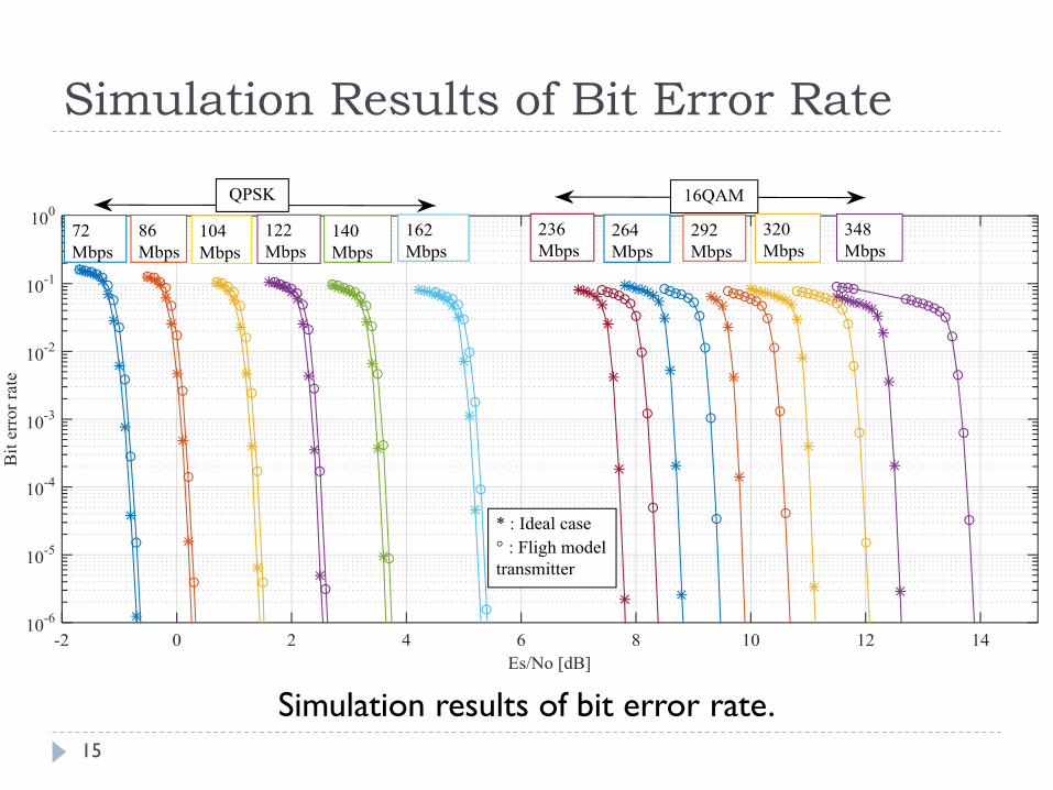
Simulation Results of Bit Error Rate
Simulation results of bit error rate.
15

Onboard small Antenna
Body-Fixed Medium Gain Antenna
Feed
point
Active
element
Passive
element
Satellite
3.8m
Ground
Station
14 dBi, 68g, 7x7cm
For high bit rate mode,
Satellite points ground
station.
16
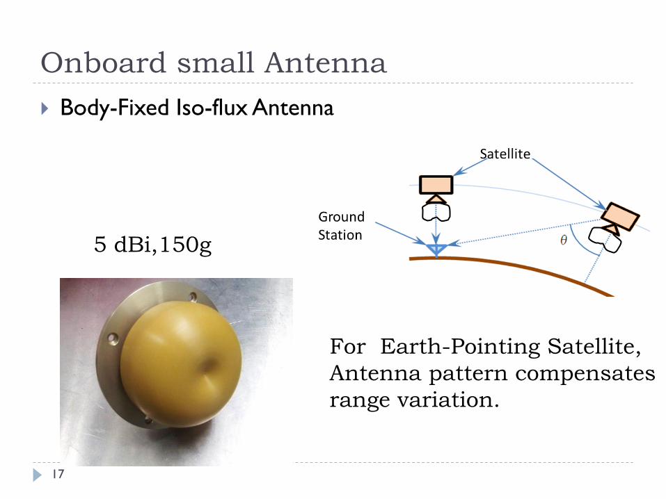
Onboard small Antenna
Body-Fixed Iso-flux Antenna
5 dBi,150g
For Earth-Pointing Satellite,
Antenna pattern compensates
range variation.
17
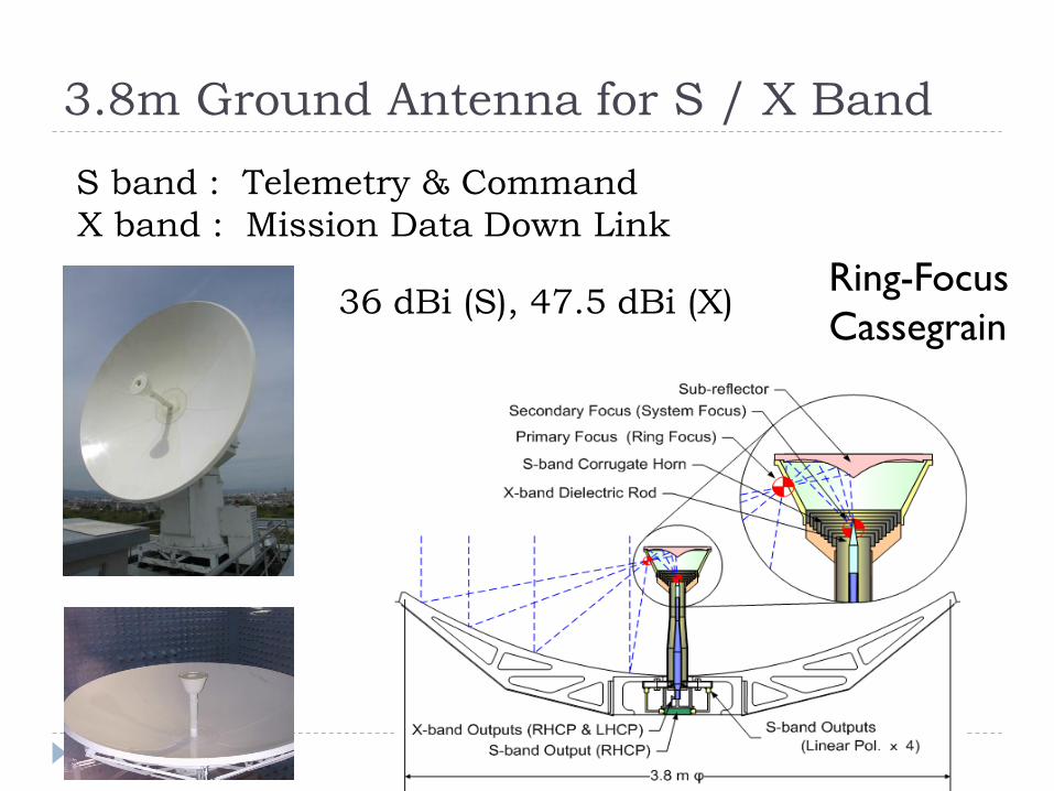
3.8m Ground Antenna for S / X Band
S band : Telemetry & Command
X band : Mission Data Down Link
Ring-Focus
Cassegrain 36 dBi (S), 47.5 dBi (X)
18
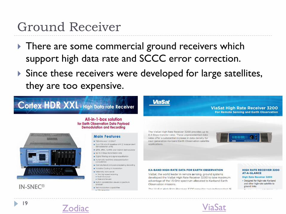
Ground Receiver
There are some commercial ground receivers which
support high data rate and SCCC error correction.
Since these receivers were developed for large satellites,
they are too expensive.
Zodiac ViaSat 19
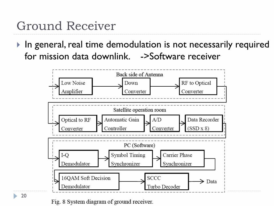
Ground Receiver
In general, real time demodulation is not necessarily required
for mission data downlink. ->Software receiver
20
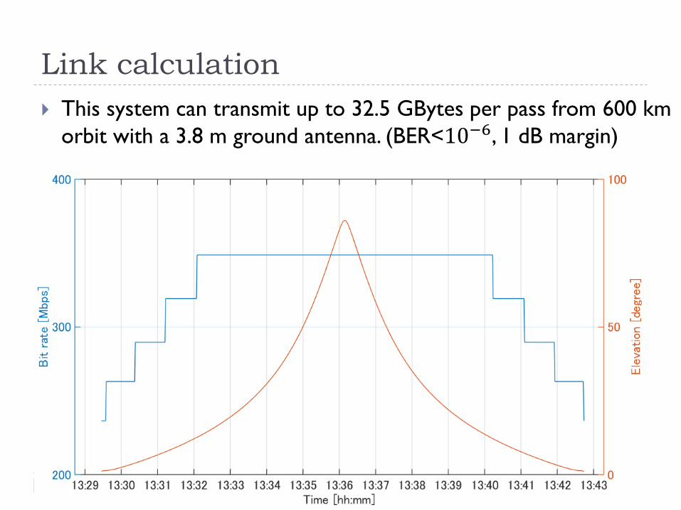
Link calculation
This system can transmit up to 32.5 GBytes per pass from 600 km
orbit with a 3.8 m ground antenna. (BER<10−6, 1 dB margin)
21

Launch
Japanese Hodoyoshi #4 satellite equipped with our downlink
system was launched at June 2014.
Hodoyoshi #3
Dnepr Launch Vehicle
Yasny, Russia
37 small satellites were launched
Hodoyoshi #4
22
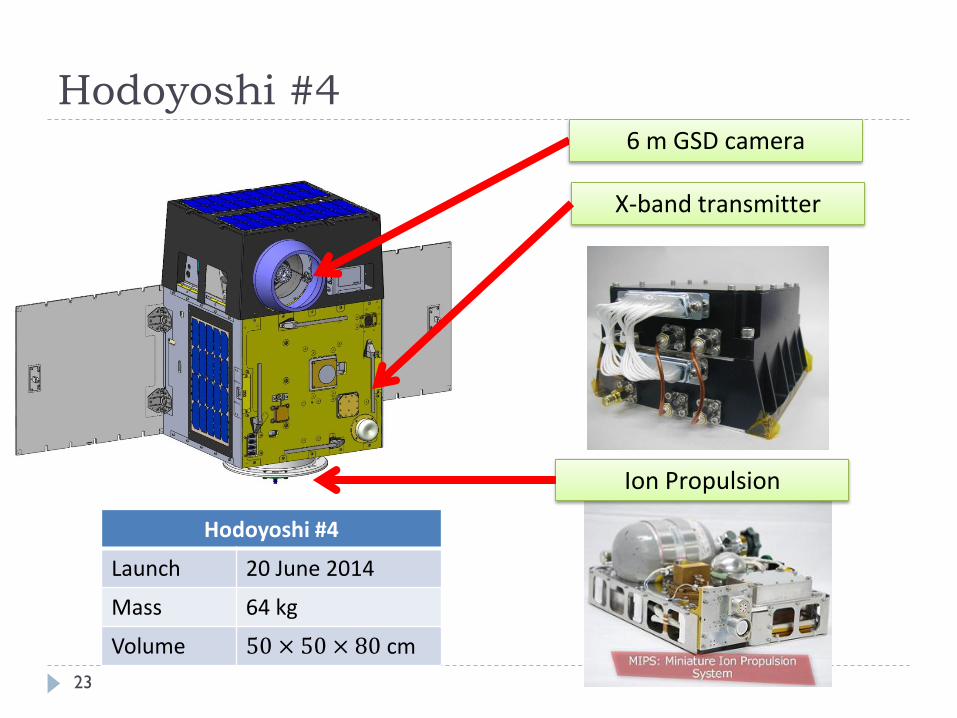
Hodoyoshi #4
Hodoyoshi #4
Launch 20 June 2014
Mass 64 kg
Volume 50 × 50 × 80 cm
6 m GSD camera
Ion Propulsion
X-band transmitter
23
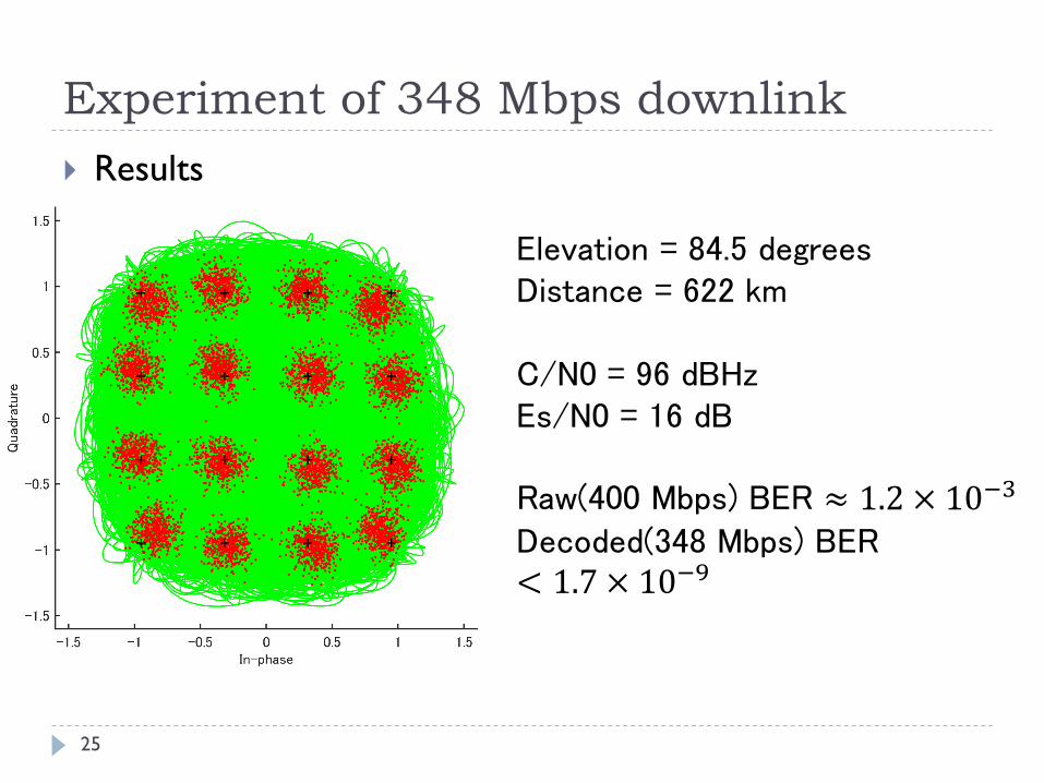
Experiment of 348 Mbps downlink
25
Results
Elevation = 84.5 degrees Distance = 622 km C/N0 = 96 dBHz Es/N0 = 16 dB Raw(400 Mbps) BER ≈ 1.2 × 10⁻³ Decoded(348 Mbps) BER < 1.7 × 10⁻⁹
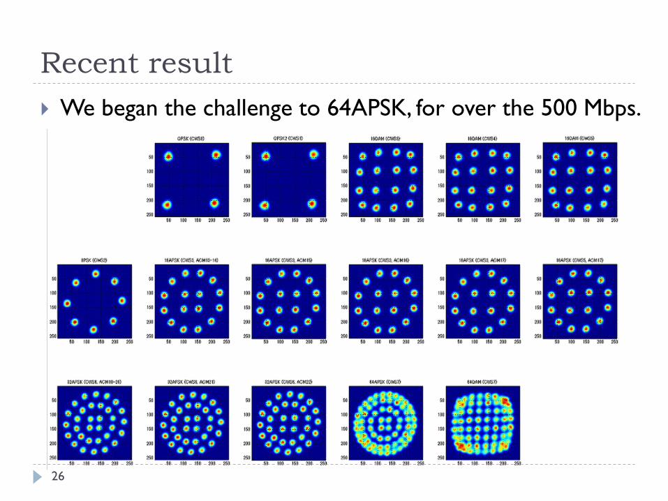
Recent result
26
We began the challenge to 64APSK, for over the 500 Mbps.
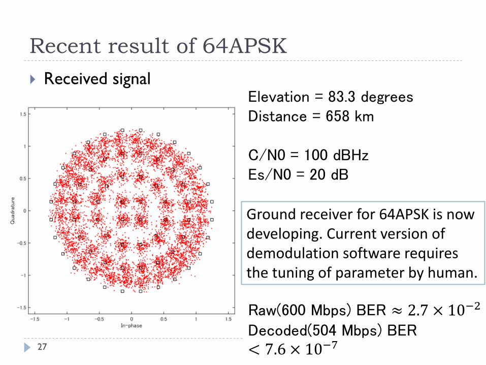
Elevation = 83.3 degrees Distance = 658 km C/N0 = 100 dBHz Es/N0 = 20 dB Raw(600 Mbps) BER ≈ 2.7 × 10⁻² Decoded(504 Mbps) BER < 7.6 × 10⁻⁷
Recent result of 64APSK
Received signal
Ground receiver for 64APSK is now developing. Current version of demodulation software requires the tuning of parameter by human.
27

Conclusion
We developed the high speed transmitter for 50-kg class satellite
and demonstrated the downlink of 348 Mbps on orbit.
We began the challenge to 64APSK modulation, for over the 500
Mbps.
By combining the two transmitters and high gain antenna (HGA,
25.5 dBi, 1.2 kg), the downlink of over the 1 Gbps from 50-kg
class satellite can be achieved.
High Gain Antenna
for 50-kg class satellite
(PROCYON Spacecraft) Photo by Mynavi
28
The End
Thank you for your attention!
Manufacturer of Transmitter Manufacturer of Power Amplifier
Manufacturer of Onboard Antenna Manufacturer of Ground Receiver
29