experiment and theory regarding the pivot pointcmu-edu.eu/repec/cmc/annals/29-v15.pdf · experiment...
TRANSCRIPT

Constanta Maritime University Annals Year XII, Vol.15
EXPERIMENT AND THEORY REGARDING THE PIVOT POINT
1BUTUSINA PAUL, ²DINU DUMITRU
1,2Constanta Maritime University, Romania ABSTRACT
The purpose of this paper is to find, in open sea, where is the pivot point (as being well established in rigid body mechanics and in ship’s manoeuvring theory). It is trying to find evolution of pivot point for a classical turning under current and swell influence. Main target of the work is to correct pivot point theory as it is presented in seafarers books. Keywords: Pivot Point, manoeuvering ship, current, swell. 1. INTRODUCTION
Pivot point of the ship turning is defined in seafarers’ publications more or less accurately as follows.
Pivot point is the point which trace the turning curve of a ship. It is located in the fore section of the ship, aftwards of the stem at 1/6-1/3 of ship’s length [3].
In general, position of the pivot point is located: a) – in the horizontal plane of the drifting center, on the vertical line of gravity center of the vessel, when: - the vessel is stationary with rudder zero, she has speed through the water and zero speed over the ground (at anchor in current); - vessel is moving straight forward or backward, with rudder midship; - the vessel has speed over the ground and zero speed through the water (ship is dead in the water, she is drifted by current in calm water); - position of the pivot point depends of the position of drifting center and this depends of the movement and its sense.
The vertical of the pivot point is the axis in respect with, during turning manoeuvre (or altering the course), the forces which act on the vessel induce the turning moments. The magnitude of these moments depends of the magnitude of the forces and the distances between positions of the application points of them and the axis of the pivot point.
Usually, it (the pivot point) is moving forward when the vessel is moving ahead and aftwards during astern moving and it is stabilizing at about 25% of ship’s length or ¼ of ship’s length from stem or stern [9].
For a stopped (without movement in respect with the water) at zero trim, in calm water and in absence of the wind, the pivot point coincides with gravity center of the vessel. Under propulsion force and the resistance of the water, the pivot point moves forward. One can consider with certain approximation, that at a stable speed, the pivot point is at 25% or 1/4L from fore. During astern moving, the pivot point will be stabilized at about 25% or 1/4L from aft. Although not intended, some publications may give the impression that the pivot point moves right aft with sternway. This is clearly not correct and can sometimes be misleading. It should also be stressed that other factors such as acceleration, shape of
hull and speed may all affect the position of the pivot point [24].
The pivot point is defined also: that position aboard the vessel about which the ship rotates when turning. In conventional vessels, the pivot point was approximately one third (1/3) of the ship’s length, measured from forward, when moving ahead.
It should be noted that when the vessel goes to anchor the pivot point moves right forward and effectively holds the bow in one position. Any forces acting on the hull, such as from wind or current, would cause the vessel to move about the hawse pipe position [14].
As a rule, close to the pivot point is placed the navigation bridge. The position of this point is determinate by ship’s gravity center position G and application point C of the rudder resistance, during moving of the vessel ahead or astern. Moving ahead, the pivot point is forward in respect with gravity center and moves more forward with the increasing speed; moving astern, it is behind gravity center and moves aftwards as the speed increase astern [30].
A. Vessel moves forward, B. The vessel moves rudder midship’s astern, rudder midship’s
Figure 1(A,B). Wrong positioning of the pivot point
As you will see later, the quotes given before (including fig.1 A and B) from impressing works and which are not random errors of expressing or editing, they are not so real as they are declared and there are necessary important corrections in order to achieve the goal for which they were introduced in seafarers training.
29
Constanta Maritime University Annals Year XII, Vol.15
The phenomenon of pivot point existence in ship manoeuvring is well known to navigators, though there is unclearly statement regarding qualitatively and quantitatively its location on a ship during various modes of operation. The available literature on ship manoeuvring and handling does not cover all aspects of pivot point in a systematic way [7].
The pivot point (PP) is the point in diametrical plan of the vessel or in the prolongation of this plan, around which the vessel swings on the tajectory which she describes.This trajectory can be a circle arch with its own center of rotation on the curve (momentary center of rotation). From PP, fore and aft of the vessel can be seen swinging with the same angular speed, even if PP is out of ship’s shape.
PP (or tactical point of turning) is located in the point of intersection between ship’s diametrical plan and the perpendicular from momentary center of rotation.In PP, ship’s tangential speed on the trajectory is ship’s speed recorded on board.
PP is important for ships’ operators because it gives some indications regarding equilibrium of the forces acting on the vessel, by its indication regarding space swept during turning and by possibility to predict ship’s orientation.
If PP is not close to 1/2L, when space swept by the vessel is πL2/4 and it is located fore or aft, necessary space for turning is 4 times larger (πL2).
Obviously PP will exist only when the vessel is in turning movement and to predict its position is not easy in all cases. In deed, for a stabilized turning on calm sea without current, PP is situated fore or aft, function of sense of movement in fore or aft area as it is presented in the most of publications, at 1/5-1/3L from fore or aft.
PP is defined as a point at distance Xp, measured from the center of gravity of the ship that satisfies the relationship [7]:
ν + Xp • r = 0 (1)
Where: v - is sway speed at the center of gravity of the ship; r - is the yaw rate. It follows, from Eq.(1) that:
Xp = -v/r (2)
Equation (2) is ill defined when the yaw rate is zero, which corresponds to a straight line motion. When the vessel movies on a straight line ahead or astern or she is in a pure sway motion, it is reasonable to consider PP at infinity [7]. In other words saying, when the vessel moves along axe X-X’ or she drifts along axe Y-Y’, there are not a PP and it is unfair to declare that PP is fore or aft function of direction of ship’s movement, as it is used in present. 2. WATER RESISTANCE AND PIVOT POINT OF A VESSEL STOPPED
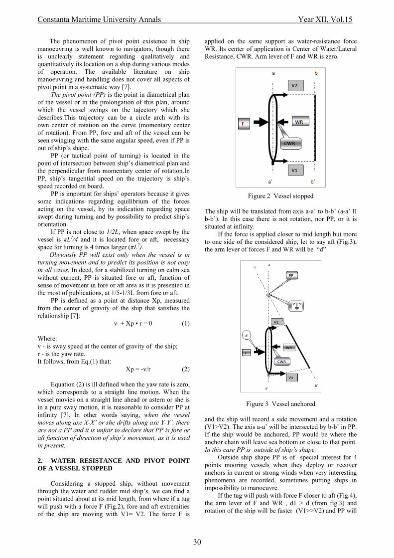
Considering a stopped ship, without movement through the water and rudder mid ship’s, we can find a point situated about at its mid length, from where if a tug will push with a force F (Fig.2), fore and aft extremities of the ship are moving with V1= V2. The force F is
applied on the same support as water-resistance force WR. Its center of application is Center of Water/Lateral Resistance, CWR. Arm lever of F and WR is zero.
Figure 2 Vessel stopped The ship will be translated from axis a-a’ to b-b’ (a-a’ II b-b’). In this case there is not rotation, nor PP, or it is situated at infinity.
If the force is applied closer to mid length but more to one side of the considered ship, let to say aft (Fig.3), the arm lever of forces F and WR will be “d”
Figure 3 Vessel anchored and the ship will record a side movement and a rotation (V1>V2). The axis a-a’ will be intersected by b-b’ in PP. If the ship would be anchored, PP would be where the anchor chain will leave sea bottom or close to that point. In this case PP is outside of ship’s shape.
Outside ship shape PP is of special interest for 4 points mooring vessels when they deploy or recover anchors in current or strong winds when very interesting phenomena are recorded, sometimes putting ships in impossibility to manoeuvre.
If the tug will push with force F closer to aft (Fig.4), the arm lever of F and WR , d1 > d (from fig.3) and rotation of the ship will be faster (V1>>V2) and PP will
30

Constanta Maritime University Annals Year XII, Vol.15
be located inside of ship’s shape close to application point of WR in ship fore part. During action of F, it appears a water flow (WF) around the bow which creates low pressure (LP) responsible for a slight forward movement of the vessel.
Figure 4 Force F applied close to aft 3. WATER RESISTANCE AND PIVOT POINT OF A MOVING VESSEL
If the ship will start to move ahead keeping her
rudder mid ship’s (fig.5), due to drifting movement with speed D, vessel will move on the resultant of propulsion speed P and D, respectively with speed P1 on its direction. Water resistance force WR increases and it will shift forward. The result is a shift of PP forward in the direction of movement.
Arm lever of F and WR, d2 > d1 and in consequence V1 >> V2, it means the vessel will turn more quickly. Even with a kick ahead, this increasing of rotation speed can be seen. This phenomenon is valid for astern movement if the tug acts forward. In such case, due to short distance between WF application point and PP, in practice, by ship handlers, it is used to consider PP as reference point for WR application point. In reality application point of WR depend of underwater shape of the vessel. 4. METHOD
To find PP position (fig.6) it was used bridge ships equipment, two marine portable GPS, watches and cameras. The two portable GPS were placed at fore and aft extremities of an offshore multipurpose vessel (fore GPS above of fore perpendicular). During ship evolution it was made movies fore and aft to record time and GPS
Figure 5 Vessel moves forward screens and pictures with bridge navigation information were taken at about each change of 100 of ship’s heading. After extracting of data from movies and pictures, position of fore and aft GPS were represented with connected linear speed. Using principles of mechanics, at intersection of perpendiculars on these speeds it was found instantaneous centre of rotation Ci around which the movement of the vessel is producing . Sa GPSa Ci = Sf GPSf Ci = 900. GPS tangentialspeeds (Sa and Sf) were decomposed on direction of ship’s centre line (Sfl and Sal) and on a perpendicular on the centre line (Sat and Sft). Transversal components Sat and Sft gives swinging movement of the vessel.Joining transversal components of GPS speeds Sat and Sft, which correspond with angular rotation speed, at
Figure 6 Method of finding PP position intersection with centre line it will be found the pivot point, PP, as it is defined in ship’s handling (as point from where fore and aft are rotating with same speed). The origin of pivot points measurements is fore perpendicular which in our case correspond with ship’s stem. PP abscissa Xpp, are negative inside of ship’s shape. PP position can be get also at intersection of diametrical plan (or center line) with a perpendicular from Ci.
There were performed few tests on real vessel and same tests on virtual ship (close as possible with particularities of real vessel), on Constanta Maritime University manoeuvring simulator. In this work we
31

Constanta Maritime University Annals Year XII, Vol.15
present a single test only due to limited space. Measurements done can be seen on figure 7.
Figure 7 Coordinates of momentary center of rotation and PP as they are indicated by manoeuvring simulator.
To see the effect of the current on position of PP
(fig. 8) one can consider a ship with rudder at a certain angle to starboard, moving with speed through water V, recorded in her center of gravity G. Speed V can be decompose longitudinally and transversally in u and v. The vessel swings around PP with angular speed r. PP, defined before, describes turning curve T, on which she moves with speed V’. The trajectory T has the momentary center of rotation Ci.It is considering the current W having opposite sense with ship’s bow swinging sense.
Figure 8 Changing of PP position in current
Figure 9 Swell effect over sway speed
Acting on axis y-y’, current speed will sum with sway speed v resulting new sway speed v1. To this new sway speed correspond a new PP1, placed more forward (Xp = -v/r < Xp1 = -v1/r), which will moves along trajectory T1 with speed V’’. For the case of current of the same sense with bow swing speed, sway speed will be reduced by current speed, resulting sway speed v2 < v. New PP2 will be located towards G and it will moves
with speed V’’’ on the trajectory T2 (the momentary radius, RT2 > RT > RT1).
To study the effect of the swell on the position of PP (fig.9), we consider a vessel turning with sway speed v, having swinging sense to port. The swell comes from starboard. During rising and falling of the ship on swell wave, displacement force acting in G1 will be decomposed in a plan parallel with floating plan, D1 and in a plan perpendicular on floating plan, A, which is canceled by Archimedes buoyant force A’. Depending of the slope of the swell wave on which is the vessel situated, the component D1 will be composed with the sway speed v, resulting a new sway speed DV. This new sway speed can be greater (fig.9.I) or smaller (fig.9.II) than old sway speed, depending of the sense of DV which will be same or opposite with sway speed before arriving swell wave. Sway speed being involved in definition of PP position, it results that, during passing from one slope to the other of the swell wave, PP will have a “jump” in respect with its position before to arrive the swell wave.
The target of the test regarding PP was the evolution of its position in open sea, in real environment conditions and how this evolution can affect manoevring versus PP theory as it is presented in marine universities. Athough here it is presented a simple turning manoeuvre in open sea, the tests were performed in various conditions and their results are presented in a separate research report. Special attention was paid for current effect.
Abscissa PP (Xpp) was measured from fore perpendicular, where one GPS was placed and it is positive forward and negative aftward.
Ordinate of momentary center of rotation (Yc) was measured from the diametrical plan of the ship and its sign is positive when momentary center of rotation is on the side of rotation of ship’s bow. Angle (Tc-Tw) between ship’s head and coming current (its direction, by navigation definition, is outgoing) has maximum value 180°, measured from the bow and being positive on the port side. 5. VESSELS PARTICULARITIES 5.1 True vessel - Offshore Supply Vessel (SV) LWL = 56.37 m; B = 14.60 m; h = 5.50 m; d = 4.75 m; D = 1500 tdw; 2 engines 2 x 1641 Kw; 2 fix propellers in Kort nozzles; 2 balanced rudders; Bow thruster = 5 mt; Max. speed = 13 knts; Height of eye = 15.25 m.
32

Constanta Maritime University Annals Year XII, Vol.15
revolutions, in following conditions:
Port engine680 rpm ahead; Bow thruster stop Total drift 321°/1,1 nd; Apparent wind 0 nd; Swell 220°/0,5-1 m/6-8 sec. Remark the boat landing on starboard Rudder 35o Starboard
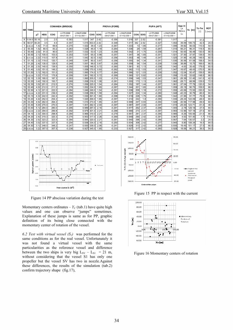
The results were recorded in table 1 from which were extracted the graphs presented in fig.13-17.
Variation of PP abscissa in respect with ship’s head is presented in fig.14 and its variation in respect with the angle between ship’s head and current in fig.15.
Figure 10 General plan of the reference vessel Analyzing positions of PP (fig. 14) one can see that ship being all the time in ahead moving, PP approaches of stern and a good part of evolution it is out of the ship shape forward. Studing relation between PP position and incidence angle, ship-current (fig.15) one can observe that the highest values of the Xpp, positive or negative are placed to an angle of incidence between vessel and current of 70°-130°, the greatest positive value being recorded at 119,5° (tab.1), the highest negative at 90°-100° and the lowest values close to incidence angle 0° or 180°.This confirm mathematical definition of PP, when the current acts perpendicular on the vessel, drifting (sway) speed increases, value of the ratio v/r increases because angular speed of swinging does not record a proportional increasing.
5.2 Simulation vessel (S1)
Figure 11 Virtual vessel
From fig. 16 one can observe that the momentary centers of rotation (Ci) are grouped, this mean that the turning swept little space although momentary centers ordinates are of quite high values (ship’s trajectory is composed of large circle arches).
Momentary fluctuation, both for PP and Ci are induced, at the slow speed of the vessel, besides the current, by the swell too, this increasing or decreasing ship’s sway or yaw rate.
Figure 12 Controls and recording data during simulation Abbreviations used in this work are: Momentary center of rotation abscissa were not
recorded, theoretically being of the same value as PP abscissa although during their measurements, it was observed that these two kind of abscissa are not equals, probably due to summoning of all errors of devices and graphic work precision.
Time - time of the record HDG/Hdg - true course (through water) Spd - true speed (through water) COG - course over ground SOG/Vt - speed over ground Lat - latitude
Long - longitude Xpp - abscissa PP from fore perpendicular (Ppv) Yc - momentary center of rotation ordinate Ci - momentary center of rotation PP - pivot point 6. THE EXPERIMENT 6.1 The test with reference vessel (SV) was a complete turning circle to starboard (fig.13), engine at minimum Table 1. Test data
Figure 13 Ship’s trajectory during the test
33
Constanta Maritime University Annals Year XII, Vol.15
ΔT HDG COGLATITUDINE
-05⁰27.000' +LONGITUDINE 011⁰32.000' + COG SOG
LATITUDINE -05⁰27.000' +
LONGITUDINE 011⁰32.000' + COG SOG
LATITUDINE -05⁰27.000' +
LONGITUDINE 011⁰32.000' +
A 15.58.53 00.16 2.0 2.0 -0.363 1.017 347 2.42 -0.356 1.018 337 2.52 -0.381 1.017 ∞ 41.0B 58.57 00.20 3.5 4.0 -0.357 1.015 353.0 2.42 -0.348 1.017 342 2.52 -0.327 1.002 39.59 106.73 42.5 24.01 16.00.20 1.42 71.0 69.6 -0.270 1.022 39.0 1.23 -0.267 1.033 13 1.85 -0.277 1.006 39.82 56.03 110.0 54.02 00.30 1.52 80.5 83.2 -0.263 1.026 46.0 1.18 -0.264 1.036 29 1.59 -0.267 1.010 66.21 96.31 119.5 60.03 00.40 2.02 91.0 90.0 -0.257 1.032 53.0 1.23 -0.258 1.042 31 1.75 -0.258 1.014 50.93 56.49 130.0 66.04 00.50 2.12 100.0 103.0 -0.253 1.037 65.0 0.98 -0.257 1.047 36 1.65 -0.251 1.021 37.50 37.97 139.0 54.05 16.01.00 2.22 110.0 107.8 -0.251 1.042 82.0 0.82 -0.256 1.053 48 1.49 -0.247 1.025 31.95 40.29 149.0 60.06 01.10 2.32 119.0 120.7 -0.249 1.047 90.0 0.67 -0.256 1.055 64 1.34 -0.241 1.030 30.56 61.58 158.0 54.07 01.20 2.42 130.0 129.5 -0.249 1.051 99.0 0.67 -0.258 1.059 54 1.54 -0.239 1.036 38.89 15.75 169.0 66.08 01.30 2.52 140.0 139.5 -0.250 1.055 146.0 0.72 -0.260 1.061 83 1.13 -0.238 1.042 -4.63 35.42 179.0 60.09 01.40 3.02 151.0 149.2 -0.252 1.058 170.0 0.93 -0.262 1.062 113 1.03 -0.237 1.047 -16.67 48.43 -170.0 66.010 01.50 3.12 162.0 151.0 -0.255 1.060 174.0 0.77 -0.264 1.066 121 1.03 -0.239 1.052 -12.04 50.47 -159.0 66.01116.02.00 3.22 173.0 175.8 -0.259 1.061 192.0 0.72 -0.269 1.060 121 0.82 -0.243 1.058 -13.43 33.62 -148.0 66.012 02.10 3.30 180.0 187.3 -0.263 1.060 205.0 1.03 -0.274 1.058 149 1.03 -0.247 1.061 -26.39 51.40 -141.0 42.013 02.20 3.42 192.0 193.7 -0.269 1.058 216.0 1.08 -0.281 1.055 173 1.13 -0.253 1.062 -28.71 68.99 -129.0 72.014 02.30 3.52 201.0 212.0 -0.274 1.056 225.0 1.54 -0.284 1.052 187 1.44 -0.257 1.061 -37.04 77.79 -120.0 54.015 02.40 4.02 212.0 211.2 -0.279 1.052 234.0 1.65 -0.287 1.044 201 1.65 -0.263 1.059 -35.19 90.75 -109.0 66.016 02.50 4.12 221.0 222.0 -0.284 1.046 249.0 1.54 -0.291 1.038 209 1.18 -0.272 1.055 -43.06 72.93 -100.0 54.01716.03.00 4.22 231.0 236.0 -0.289 1.038 258.0 1.59 -0.294 1.027 224 1.34 -0.280 1.048 -42.23 30.79 -90.0 60.018 03.10 4.32 242.0 242.4 -0.292 1.030 261.0 1.80 -0.298 1.019 228 1.75 -0.286 1.042 -31.95 91.77 -79.0 66.019 03.20 4.42 252.0 254.2 -0.295 1.020 269.0 1.85 -0.297 1.010 242 1.8 -0.290 1.035 -28.24 122.09 -69.0 60.020 03.30 4.52 262.0 264.2 -0.296 1.010 273.0 1.85 -0.297 0.999 247 0.93 -0.294 1.028 -30.56 117.98 -59.0 60.021 03.40 5.00 270.0 270.0 -0.297 1.001 282.0 2.00 -0.297 0.987 257 2.00 -0.297 1.015 -25.00 123.71 -51.0 48.022 03.50 5.12 284.0 280.0 -0.295 0.989 287.0 2.16 -0.291 0.977 262 2.37 -0.296 1.005 -2.78 129.18 -37.0 84.02316.04.00 2.22 294.0 289.8 -0.292 0.979 301.0 2.21 -0.288 0.968 273 2.31 -0.297 0.993 -12.96 107.18 -27.0 60.024 04.10 2.32 300.0 298.8 -0.284 0.966 310.0 2.21 -0.279 0.957 281 2.37 -0.295 0.985 -9.26 105.56 -21.0 66.025 04.20 2.42 319.3 320.3 -0.274 0.953 317.0 2.26 -0.269 0.949 290 2.42 -0.291 0.967 4.63 101.40 -1.7 115.826 04.30 2.52 323.2 323.5 -0.264 0.944 320.0 2.21 -0.261 0.940 298 2.42 -0.284 0.957 7.64 130.57 2.2 24.027 04.40 3.02 337.5 337.5 -0.254 0.936 334.0 2.16 -0.250 0.934 308 2.42 -0.277 0.945 8.80 108.34 16.5 84.028 04.50 3.12 348.0 348.2 -0.247 0.930 339.0 2.06 -0.241 0.929 313 2.42 -0.269 0.935 19.45 101.17 27.0 66.02916.05.00 3.22 357.0 357.5 -0.238 0.927 345.0 1.85 -0.233 0.927 317 2.42 -0.260 0.928 18.06 86.21 36.0 54.0
ROT [◦/min]
Tc-Tw [◦]Yc [m]NR
Xpp DE LA
PROVA [m]
PUPA (AFT)
TIME
PROVA (FORE)COMANDA (BRIDGE)
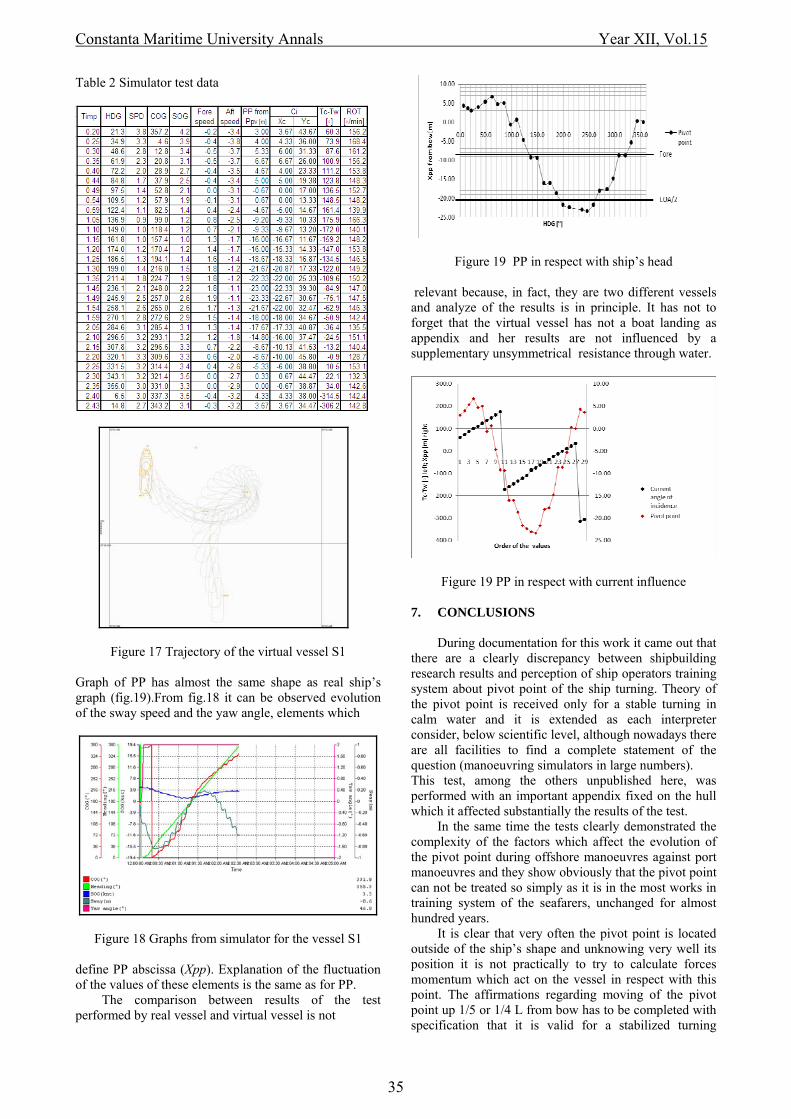
Figure 14 PP abscissa variation during the test Momentary centers ordinates – YC (tab.1) have quite high values and one can observe “jumps” sometimes. Explanation of these jumps is same as for PP, graphic definition of its being close connected with the momentary center of rotation of the vessel. 6.2 Test with virtual vessel (S1) was performed for the same conditions as for the real vessel. Unfortunately it was not found a virtual vessel with the same particularities as the reference vessel and difference between the two ships is very big LSV – LS1 = 21 m, without considering that the vessel S1 has only one propeller but the vessel SV has two in nozzle.Against these differences, the results of the simulation (tab.2) confirm trajectory shape (fig.17),
Figure 15 PP in respect with the current
Figure 16 Momentary centers of rotation
34
Constanta Maritime University Annals Year XII, Vol.15
Table 2 Simulator test data
Figure 17 Trajectory of the virtual vessel S1 Graph of PP has almost the same shape as real ship’s graph (fig.19).From fig.18 it can be observed evolution of the sway speed and the yaw angle, elements which
Figure 18 Graphs from simulator for the vessel S1 define PP abscissa (Xpp). Explanation of the fluctuation of the values of these elements is the same as for PP.
The comparison between results of the test performed by real vessel and virtual vessel is not
Figure 19 PP in respect with ship’s head relevant because, in fact, they are two different vessels and analyze of the results is in principle. It has not to forget that the virtual vessel has not a boat landing as appendix and her results are not influenced by a supplementary unsymmetrical resistance through water.
Figure 19 PP in respect with current influence 7. CONCLUSIONS
During documentation for this work it came out that there are a clearly discrepancy between shipbuilding research results and perception of ship operators training system about pivot point of the ship turning. Theory of the pivot point is received only for a stable turning in calm water and it is extended as each interpreter consider, below scientific level, although nowadays there are all facilities to find a complete statement of the question (manoeuvring simulators in large numbers). This test, among the others unpublished here, was performed with an important appendix fixed on the hull which it affected substantially the results of the test.
In the same time the tests clearly demonstrated the complexity of the factors which affect the evolution of the pivot point during offshore manoeuvres against port manoeuvres and they show obviously that the pivot point can not be treated so simply as it is in the most works in training system of the seafarers, unchanged for almost hundred years.
It is clear that very often the pivot point is located outside of the ship’s shape and unknowing very well its position it is not practically to try to calculate forces momentum which act on the vessel in respect with this point. The affirmations regarding moving of the pivot point up 1/5 or 1/4 L from bow has to be completed with specification that it is valid for a stabilized turning
35

Constanta Maritime University Annals Year XII, Vol.15
manoeuvre in water area with ideal conditions and it is not a general statement as it is understanding from the most works regarding the matter or completely wrong to assert that the pivot point is located in a certain place during streight way ahead or astern.
It was demonstrated, in special for low speed, huge influence of the current and the swell on the p;ivot point abscissa evolution.
Paraphrasing professor Rayleigh who said: “It happens not infrequently that results in the form of 'laws' are put forward as nobelties on the basis of elaborate experiments, which might have been predicted a priori after a few minutes consideration”, we can say: the results of the pivot point study which could be enunciated after a few (good) minutes consideration, they needed experiments of which one was presented in this work and may be they will need more experiments on the ship models and manoeuvring simulators and may be even then it will not be sure that the complete theory of the pivot point will be assimilated by the seafarers training books. 8. REFERENCES [1] Artyszuk Jaroslaw - Evaluation of uniform current dynamic effect in practical ship manoeuvring, Szczecin Maritime Academy, Annual of navigation 8/2004 [2] Bertram, Victor - Practical ship hydrodynamics, Butterworth Heineman (2000) [3] Bibicescu Ghe. şi colectiv - Lexicon maritim englez-român, Editura ştiinţifică, 1971 [4] Butuşină Paul, Dinu Dumitru – Water resistance force – pivot point, Annals of Mechanical, Industrial and Maritime Engineering, vol.XII, Ovidius University Constanţa, 2010 [5] Cauvier, Hugues - Is the Pivot Point realy a pivot point? A study on the rotation and sideways motion of ships, [email protected] (2008) [6] Chase, G. Andy - The Moving Pivot Point, The Northern Mariner/Le Marin du Nord, IX, July (1999); [7] Ching-Yaw Tzeng - Analysis of the pivot point for a turning ship, Journal of Marine Science and Technology, vol.6, no.1 (1998)
[28] SOGREAH Consulting Engineering – Proceedings, 1-st International Symposium on Ship Approach and Berthing Manoeuvres, Grenoble, 1977
[8] Che Wan, Mohd Noor Bin Che, Wan Othman - Manoeuvring prediction of offshore supply vessel, Faculty of Mechanical Engineering, Universiti Teknologi Malaysia May 2009 [9] Deboveanu Marin – Tratat de manevra navei, ed. Lumina Lex 1999-2003 [10] Dictionar enciclopedic, vol.II, Editura enciclopedică,1996 [11] Dinu Dumitru, Popa Dan - Jet Maneuvering of ROVs. A Mathematical Model, Revista Hidraulica Nr.2(24), iulie, 2009, ISSN 1453-73-03
[12] Dinu Dumitru – Hydraulics and hydraulic machines, Ed. Sigma Trading Metafora, 1999 [13] Dinu Dumitru – Mecanica fluidelor pentru navigatori, ed. Nautica, 2010 [14] House David L. – Ship Handling, Butterworth Heinemann, 2007 [15] Journée J.M.J. - Prediction of Speed and Behaviour of a Ship in a Seaway, Report 0427-P, Delft University of Technology, Ship Hydromechanics Laboratory, 1976; [16] Lewis, E. V. - Principles of Naval Architecture, SNAME, NJ (1989) [17] López Eloy, Velasc Francisco J., Moyano Emiliano, Rueda Teresa M. - Full-scale manoeuvering trials simulation, Journal of Maritime Research, Vol. I. No. 3, pp. 37-50, 2004 [18] Maier Viorel – Mecanica şi construcţia navei, Editura Tehnică, 1987 [19] MSC 76/23/Add.1 - Standards for ship manoeuvrability , Resolution MSC.137(76) (2002) [20]30. Obreja Dan, Crudu Liviu, Păcuraru-Popoiu Săndiţa - Manevrabilitatea navei, Galaţi University Press (2008) [21] Port Ravel Ship Handling Training Center - Course Manual, 2010 [22] Rawson, K.J. and Tupper, E.C. - Basic Ship Theory, Butterworth Heineman (2001) [23] Resolution MSC.235(82) - Adoption of the guidelines for the design and construction of offshore supply vessels, 1 December 2006 [24] Rowe, R.W. - The ship handler’s guide, The Nautical Institute, London (1996) [25] RINA Rules - Ship manoeuvrability, MANOVR, 2003 [26] RINA INDUSTRY S.p.A.,TERMINAL ALPI ADRITICO, TERMINALE DI RIGASSIFICAZIONE OFF-SHORE - Studio di Manovrabilità, 2008 [27] Schneekluth, H. and Bertram, Volker - Ship Design for Efficiency and Economy, Butterworth Heineman (1998)
[29] Sogreah - Port Revel Shiphandling Technical Documentation, 2009 [30] Universitatea Maritimă Constanţa – Curs de manevra navei pentru învăţământ cu frecvenţă redusă, 2007 [31] Volker Bertram – Practical ships hydrodynamics, Buttervorth Heinemann, 2000 [32] Zamfir, P.I. and Bartalos Bela - Manevra navelor cu propulsie mecanică, note de curs, Institutul de marină „Mircea cel Batrân”, 1979.
36