experience using radspeed pro edge and its operation at
TRANSCRIPT
RAD
No.85 (2019.3)
1. Hospital Introduction
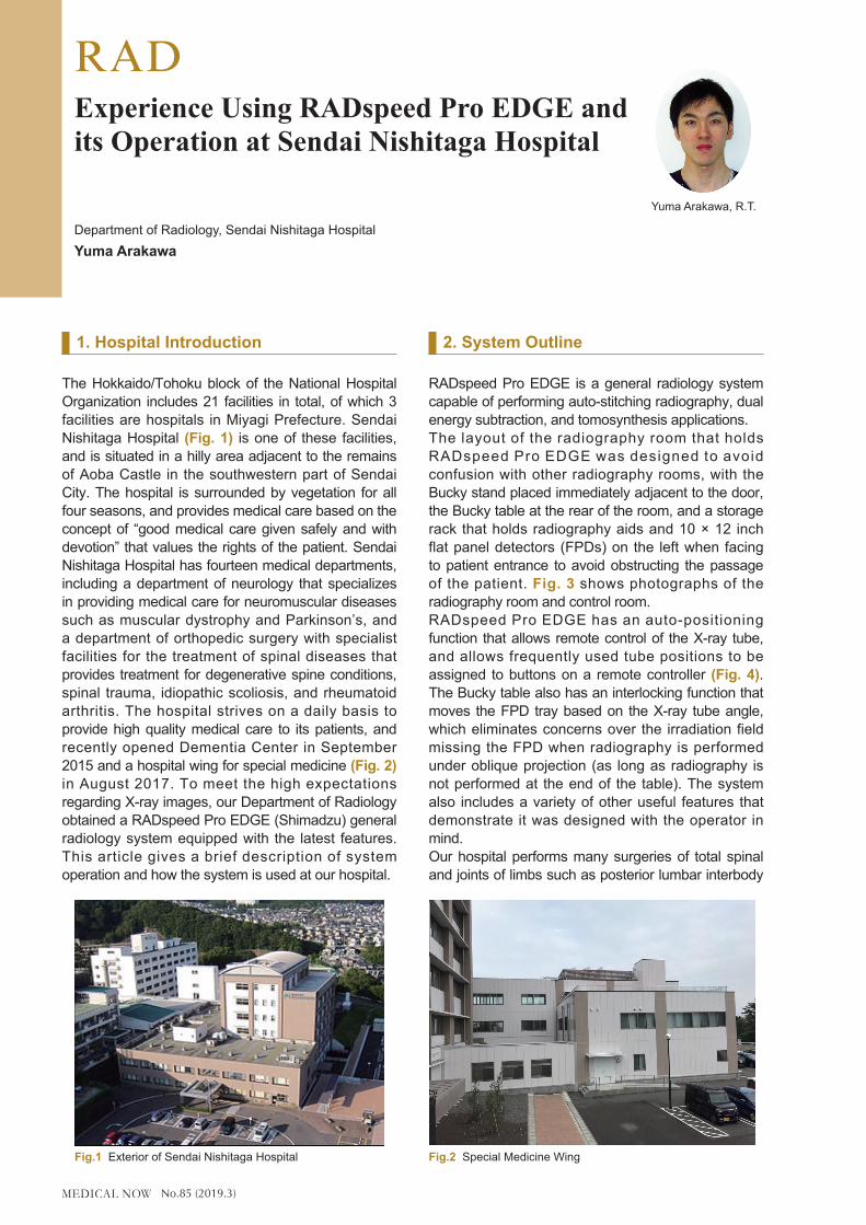
The Hokkaido/Tohoku block of the National Hospital Organization includes 21 facilities in total, of which 3 facilities are hospitals in Miyagi Prefecture. Sendai Nishitaga Hospital (Fig. 1) is one of these facilities, and is situated in a hilly area adjacent to the remains of Aoba Castle in the southwestern part of Sendai City. The hospital is surrounded by vegetation for all four seasons, and provides medical care based on the concept of “good medical care given safely and with devotion” that values the rights of the patient. Sendai Nishitaga Hospital has fourteen medical departments, including a department of neurology that specializes in providing medical care for neuromuscular diseases such as muscular dystrophy and Parkinson’s, and a department of orthopedic surgery with specialist facilities for the treatment of spinal diseases that provides treatment for degenerative spine conditions, spinal trauma, idiopathic scoliosis, and rheumatoid arthritis. The hospital strives on a daily basis to provide high quality medical care to its patients, and recently opened Dementia Center in September 2015 and a hospital wing for special medicine (Fig. 2) in August 2017. To meet the high expectations regarding X-ray images, our Department of Radiology obtained a RADspeed Pro EDGE (Shimadzu) general radiology system equipped with the latest features. This article gives a brief description of system operation and how the system is used at our hospital.
2. System Outline
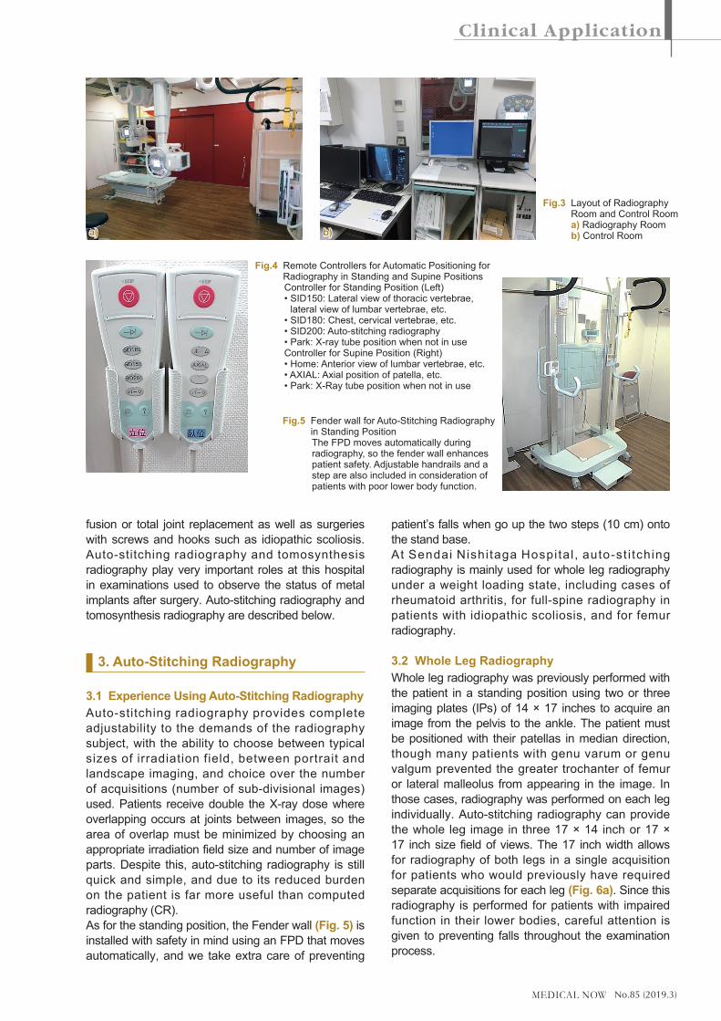
RADspeed Pro EDGE is a general radiology system capable of performing auto-stitching radiography, dual energy subtraction, and tomosynthesis applications.The layout of the radiography room that holds RADspeed Pro EDGE was designed to avoid confusion with other radiography rooms, with the Bucky stand placed immediately adjacent to the door, the Bucky table at the rear of the room, and a storage rack that holds radiography aids and 10 × 12 inch flat panel detectors (FPDs) on the left when facing to patient entrance to avoid obstructing the passage of the patient. Fig. 3 shows photographs of the radiography room and control room.RADspeed Pro EDGE has an auto-positioning function that allows remote control of the X-ray tube, and allows frequently used tube positions to be assigned to buttons on a remote controller (Fig. 4). The Bucky table also has an interlocking function that moves the FPD tray based on the X-ray tube angle, which eliminates concerns over the irradiation field missing the FPD when radiography is performed under oblique projection (as long as radiography is not performed at the end of the table). The system also includes a variety of other useful features that demonstrate it was designed with the operator in mind.Our hospital performs many surgeries of total spinal and joints of limbs such as posterior lumbar interbody
Experience Using RADspeed Pro EDGE and its Operation at Sendai Nishitaga Hospital
Department of Radiology, Sendai Nishitaga HospitalYuma Arakawa
Yuma Arakawa, R.T.
Fig.1 Exterior of Sendai Nishitaga Hospital Fig.2 Special Medicine Wing
No.85 (2019.3)
fusion or total joint replacement as well as surgeries with screws and hooks such as idiopathic scoliosis. Auto-stitching radiography and tomosynthesis radiography play very important roles at this hospital in examinations used to observe the status of metal implants after surgery. Auto-stitching radiography and tomosynthesis radiography are described below.
3. Auto-Stitching Radiography
3.1 Experience Using Auto-Stitching RadiographyAuto-stitching radiography provides complete adjustability to the demands of the radiography subject, with the ability to choose between typical sizes of irradiation field, between portrait and landscape imaging, and choice over the number of acquisitions (number of sub-divisional images) used. Patients receive double the X-ray dose where overlapping occurs at joints between images, so the area of overlap must be minimized by choosing an appropriate irradiation field size and number of image parts. Despite this, auto-stitching radiography is still quick and simple, and due to its reduced burden on the patient is far more useful than computed radiography (CR).As for the standing position, the Fender wall (Fig. 5) is installed with safety in mind using an FPD that moves automatically, and we take extra care of preventing
patient’s falls when go up the two steps (10 cm) onto the stand base.At Sendai Nishi taga Hospital , auto-st i tching radiography is mainly used for whole leg radiography under a weight loading state, including cases of rheumatoid arthritis, for full-spine radiography in patients with idiopathic scoliosis, and for femur radiography.
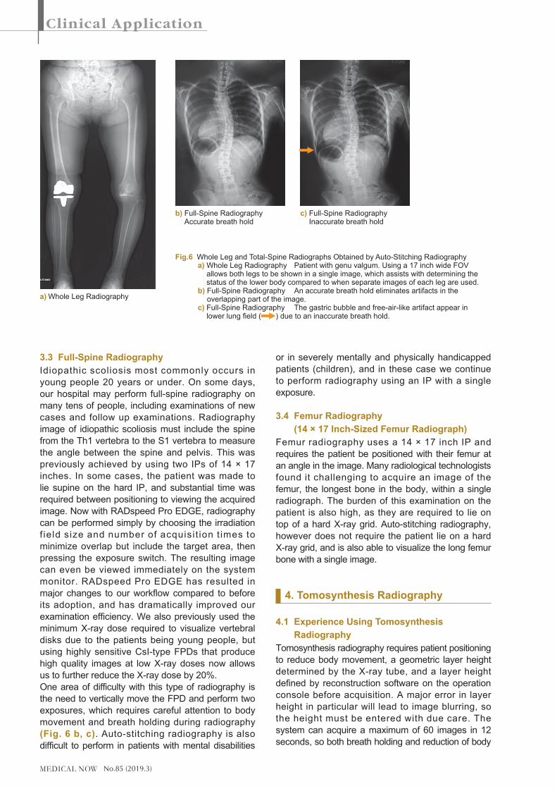
3.2 Whole Leg RadiographyWhole leg radiography was previously performed with the patient in a standing position using two or three imaging plates (IPs) of 14 × 17 inches to acquire an image from the pelvis to the ankle. The patient must be positioned with their patellas in median direction, though many patients with genu varum or genu valgum prevented the greater trochanter of femur or lateral malleolus from appearing in the image. In those cases, radiography was performed on each leg individually. Auto-stitching radiography can provide the whole leg image in three 17 × 14 inch or 17 × 17 inch size field of views. The 17 inch width allows for radiography of both legs in a single acquisition for patients who would previously have required separate acquisitions for each leg (Fig. 6a). Since this radiography is performed for patients with impaired function in their lower bodies, careful attention is given to preventing falls throughout the examination process.
Fig.3 Layout of Radiography Room and Control Room a) Radiography Room b) Control Room
Fig.4 Remote Controllers for Automatic Positioning for Radiography in Standing and Supine Positions
Controller for Standing Position (Left) •SID150:Lateralviewofthoracicvertebrae,
lateral view of lumbar vertebrae, etc. •SID180:Chest,cervicalvertebrae,etc. •SID200:Auto-stitchingradiography •Park:X-raytubepositionwhennotinuse Controller for Supine Position (Right) •Home:Anteriorviewoflumbarvertebrae,etc. •AXIAL:Axialpositionofpatella,etc. •Park:X-Raytubepositionwhennotinuse
Fig.5 Fender wall for Auto-Stitching Radiography in Standing Position
The FPD moves automatically during radiography, so the fender wall enhances patient safety. Adjustable handrails and a step are also included in consideration of patients with poor lower body function.
b)a)
No.85 (2019.3)
3.3 Full-Spine RadiographyIdiopathic scoliosis most commonly occurs in young people 20 years or under. On some days, our hospital may perform full-spine radiography on many tens of people, including examinations of new cases and follow up examinations. Radiography image of idiopathic scoliosis must include the spine from the Th1 vertebra to the S1 vertebra to measure the angle between the spine and pelvis. This was previously achieved by using two IPs of 14 × 17 inches. In some cases, the patient was made to lie supine on the hard IP, and substantial time was required between positioning to viewing the acquired image. Now with RADspeed Pro EDGE, radiography can be performed simply by choosing the irradiation f ield size and number of acquisi t ion t imes to minimize overlap but include the target area, then pressing the exposure switch. The resulting image can even be viewed immediately on the system monitor. RADspeed Pro EDGE has resulted in major changes to our workflow compared to before its adoption, and has dramatically improved our examination efficiency. We also previously used the minimum X-ray dose required to visualize vertebral disks due to the patients being young people, but using highly sensitive CsI-type FPDs that produce high quality images at low X-ray doses now allows us to further reduce the X-ray dose by 20%.One area of difficulty with this type of radiography is the need to vertically move the FPD and perform two exposures, which requires careful attention to body movement and breath holding during radiography (Fig. 6 b, c). Auto-stitching radiography is also difficult to perform in patients with mental disabilities
or in severely mentally and physically handicapped patients (children), and in these case we continue to perform radiography using an IP with a single exposure.
3.4 Femur Radiography (14 × 17 Inch-Sized Femur Radiograph)
Femur radiography uses a 14 × 17 inch IP and requires the patient be positioned with their femur at an angle in the image. Many radiological technologists found it challenging to acquire an image of the femur, the longest bone in the body, within a single radiograph. The burden of this examination on the patient is also high, as they are required to lie on top of a hard X-ray grid. Auto-stitching radiography, however does not require the patient lie on a hard X-ray grid, and is also able to visualize the long femur bone with a single image.
4. Tomosynthesis Radiography
4.1 Experience Using Tomosynthesis Radiography
Tomosynthesis radiography requires patient positioning to reduce body movement, a geometric layer height determined by the X-ray tube, and a layer height defined by reconstruction software on the operation console before acquisition. A major error in layer height in particular will lead to image blurring, so the height must be entered with due care. The system can acquire a maximum of 60 images in 12 seconds, so both breath holding and reduction of body
Fig.6 Whole Leg and Total-Spine Radiographs Obtained by Auto-Stitching Radiography a) Whole Leg Radiography Patient with genu valgum. Using a 17 inch wide FOV
allows both legs to be shown in a single image, which assists with determining the status of the lower body compared to when separate images of each leg are used.
b) Full-Spine Radiography An accurate breath hold eliminates artifacts in the overlapping part of the image.
c) Full-Spine Radiography The gastric bubble and free-air-like artifact appear in lower lung field ( ) due to an inaccurate breath hold.
a) Whole Leg Radiography
b) Full-Spine Radiography Accurate breath hold
c) Full-Spine Radiography Inaccurate breath hold
No.85 (2019.3)
movement require due attention. After radiography is complete, raw images are transmitted to a dedicated reconstruction workstation, where reconstruction is executed automatically according to a preset parameters. Reconstruction can be performed quickly by the filtered back projection (FBP) method, which takes around just 10 seconds (for 60 images).Reconstruction may then be repeated manually using Shimadzu’s proprietary T-smart (tomosynthesis-Shimadzu metal artifact reduction technology) reconstruct ion method, which uses i terat ive reconstruction (IR). T-smart reduces metal artifacts and allows observation of bone trabeculae around metal implants.T-smart with eight iterations requires around 2 minutes to complete, and is dramatically more useful for patients with metal implants than the prior FBP method.At this hospital, the FBP method is used during diagnosis of lumbar vertebral dysplasia in children and lumbar spondylolysis in teenagers when high-resolution and highly detailed tomographic images are needed at a reduced X-ray dose, and T-smart is used
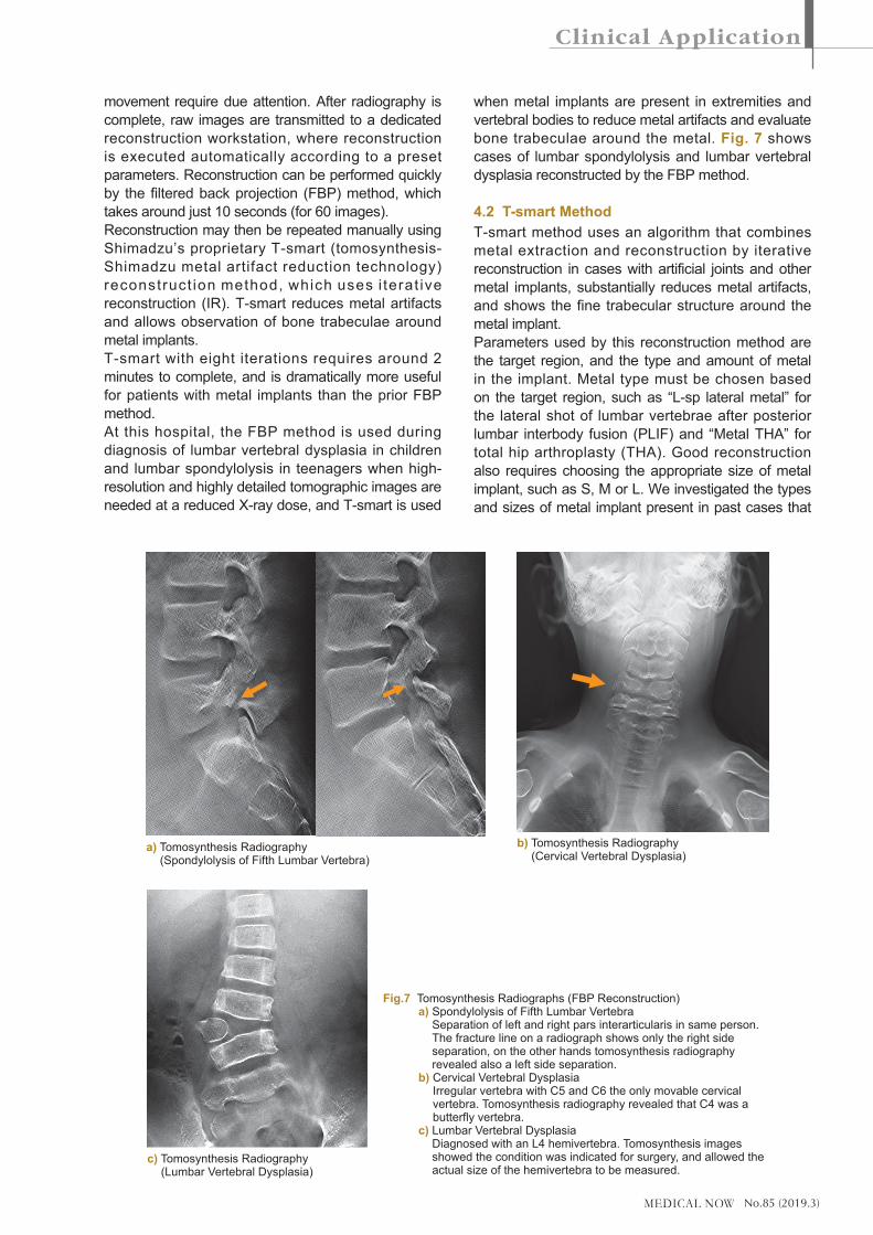
when metal implants are present in extremities and vertebral bodies to reduce metal artifacts and evaluate bone trabeculae around the metal. Fig. 7 shows cases of lumbar spondylolysis and lumbar vertebral dysplasia reconstructed by the FBP method.
4.2 T-smart MethodT-smart method uses an algorithm that combines metal extraction and reconstruction by iterative reconstruction in cases with artificial joints and other metal implants, substantially reduces metal artifacts, and shows the fine trabecular structure around the metal implant.Parameters used by this reconstruction method are the target region, and the type and amount of metal in the implant. Metal type must be chosen based on the target region, such as “L-sp lateral metal” for the lateral shot of lumbar vertebrae after posterior lumbar interbody fusion (PLIF) and “Metal THA” for total hip arthroplasty (THA). Good reconstruction also requires choosing the appropriate size of metal implant, such as S, M or L. We investigated the types and sizes of metal implant present in past cases that
Fig.7 Tomosynthesis Radiographs (FBP Reconstruction) a) Spondylolysis of Fifth Lumbar Vertebra
Separation of left and right pars interarticularis in same person. The fracture line on a radiograph shows only the right side separation, on the other hands tomosynthesis radiography revealed also a left side separation.
b) Cervical Vertebral Dysplasia Irregular vertebra with C5 and C6 the only movable cervical vertebra. Tomosynthesis radiography revealed that C4 was a butterfly vertebra.
c) Lumbar Vertebral Dysplasia Diagnosed with an L4 hemivertebra. Tomosynthesis images showed the condition was indicated for surgery, and allowed the actual size of the hemivertebra to be measured.
a) Tomosynthesis Radiography (Spondylolysis of Fifth Lumbar Vertebra)
c) Tomosynthesis Radiography (Lumbar Vertebral Dysplasia)
b) Tomosynthesis Radiography (Cervical Vertebral Dysplasia)
No.85 (2019.3)
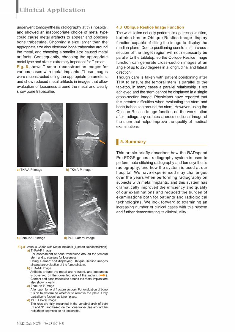
underwent tomosynthesis radiography at this hospital, and showed an inappropriate choice of metal type could cause metal artifacts to appear and obscure bone trabeculae. Choosing a size larger than the appropriate size also obscured bone trabeculae around the metal, and choosing a smaller size caused metal artifacts. Consequently, choosing the appropriate metal type and size is extremely important for T-smart.Fig. 8 shows T-smart reconstruction images for various cases with metal implants. These images were reconstructed using the appropriate parameters, and show reduced metal artifacts in images that allow evaluation of looseness around the metal and clearly show bone trabeculae.
4.3 Oblique Reslice Image FunctionThe workstation not only performs image reconstruction, but also has an Oblique Reslice Image display function capable of tilting the image to display the median plane. Due to positioning constraints, a cross-section of the target region will not necessarily be parallel to the tabletop, so the Oblique Reslice Image function can generate cross-section images at an angle of up to ±20 degrees in a longitudinal and lateral direction.Though care is taken with patient positioning after THA to ensure the femoral stem is parallel to the tabletop, in many cases a parallel relationship is not achieved and the stem cannot be displayed in a single cross-section image. Physicians have reported that this creates difficulties when evaluating the stem and bone trabeculae around the stem. However, using the Oblique Reslice Image function on the workstation after radiography creates a cross-sectional image of the stem that helps improve the quality of medical examinations.
5. Summary
This article briefly describes how the RADspeed Pro EDGE general radiography system is used to perform auto-stitching radiography and tomosynthesis radiography, and how the system is used at our hospital. We have experienced may challenges over the years when performing radiography on subjects with metal implants, and this system has dramatically improved the efficiency and quality of our examinations and reduced the burden of examinations both for patients and radiological technologists. We look forward to examining an increasing number of clinical cases with this system and further demonstrating its clinical utility.
Fig.8 Various Cases with Metal Implants (T-smart Reconstruction) a) THA A-P Image For assessment of bone trabeculae around the femoral
stem and to evaluate for looseness. Using T-smart and displaying Oblique Reslice images
allowed an evaluation of the femoral stem. b) TKA A-P Image Artifacts around the metal are reduced, and looseness
is observed on the lower leg side of the implant ( ). Cement and bone trabeculae around the metal implant are also shown clearly.
c) Femur A-P Image After open femoral fracture surgery. For evaluation of bone
fusion to determine whether to remove the plate. Only partial bone fusion has taken place.
d) PLIF Lateral Image The rods are fully implanted in the vertebral arch of both
L5 and S1, and based on the bone trabeculae around the rods there seems to be no looseness.
a) THA A-P Image b) TKA A-P Image
c) Femur A-P Image d) PLIF Lateral Image