experience in numerical simulation of turbulent wet-steam …
TRANSCRIPT

Paper ID: ETC2017-314 Proceedings of 12th European Conference on Turbomachinery Fluid dynamics & Thermodynamics ETC12, April 3-7, 2017; Stockholm, Sweden
OPEN ACCESS Downloaded from www.euroturbo.eu
1 Copyright © by the Authors
EXPERIENCE IN NUMERICAL SIMULATION OF TURBULENT
WET-STEAM FLOW IN THE LAST STAGE OF A HIGH-POWER
CONDENSING TURBINE UNDER CONDITIONS DEFINED BY
FULL-SCALE EXPERIMENTS AT A POWER PLANT
S.A. Galaev1 - V.V. Ris1 - L.L. Simoyu†2 - E.M. Smirnov1
1 Department of Fluid Dynamics, Combustion and Heat Transfer, Peter the Great Saint-Petersburg
Polytechnic University, Saint-Petersburg, Russia, [email protected], [email protected]
2 All-Russian Thermal Engineering Institute (VTI), Moscow, Russia
ABSTRACT
Three-dimensional RANS-based numerical simulation of wet steam flow through last stage
of a LP turbine has been performed. The stage geometry and flow conditions are defined in
accordance with data of full-scale experiments on a LMZ steam turbine with power output of
1200 MW. Calculations have been carried out with the ANSYS CFX 12.1 package. Using the
mixing-plane approach and the SST turbulence model, steady-state flows both in the nozzle
and in the rotor blade channels are computed. Effects of blade deformation under the
centrifugal force action are analyzed. Results of computations are compared with
experimental data for outlet section flow parameters. The better agreement between
computational and experimental data has been achieved when the blade deformation under
centrifugal force action has been taken into account.
KEYWORDS
LP STEAM TURBINE, NUMERICAL SIMULATION, RANS-APPOACH, FULL-SCALE
EXPERIMENTAL DATA
NOMENCLATURE
c0 stage inlet absolute velocity
c2 stage outlet absolute velocity
h0 = i0* – i2t available stage isentropic enthalpy change
i0 stage inlet enthalpy
i1 rotor inlet enthalpy
i1t stator outlet isentropic enthalpy
i2t stage outlet isentropic enthalpy
i2t rotor outlet isentropic enthalpy
L blade length
pref reference pressure
w1 rotor inlet relative velocity
Δh1 = i1 – i1t stator losses
Δh2 = i2 – i2t rotor losses
ζ1 = Δh1/(i0 – i1t + c02/2) stator losses coefficient
ζ2 = Δh2/(i1 – i2t + w12/2) rotor losses coefficient
ηu = (h0 – Δh1 – Δh2 – c22/2)/h0 stage efficiency
DB deformed blade
LMZ Leningradsky Metallichesky Zavod

2
NDB non-deformed blade
VTI All-Union Thermal Engineering Institute, Moscow
INTRODUCTION
Experimental and numerical studies of wet steam flow in LP turbines attract permanent
attention. Studies of last years are focused mostly on effects of steam condensation on flow
specifics and the stage efficiency. For instance, results of numerical investigations of wet steam
flow in a three-stage LP steam turbine test rig were presented in papers by Gerber et al. (2007), and
by Starzmann et al. (2011). Experiments with a steam turbine scale model provided flow
measurement data, which were used for comparisons with numerical results. In both the studies the
ANSYS CFX package was used for calculations. The effect of different theoretical models for
nucleation and droplet growth were examined. Paper by Wroblewski et al. (2009) presents the full-
scale experimental investigations of steam flow with condensation in the LP part of a 360 MW
turbine. The measurement results formed a basis for CFD modeling that was performed with an
in-house code using the RANS-approach coupled with the SST k-ω turbulence model. The
numerical results and experimental data obtained were compared and discussed. A numerical study
dealing with simulation of unsteady 3D wet-steam flows through three-stage stator-rotor blade rows
in a LP steam turbine model was presented in (Yamamoto et al., 2010, and Miyake et al., 2013).
Flow conditions were defined by experiments conducted by Mitsubishi Heavy Industries. The
computations were performed with an in-house code on the base of non-equilibrium condensation
flow models. Results for flows with different inlet flow conditions were reported and compared
with each other.
In the reports listed above, as well as in other similar studies, effects of rotating blade geometry
changes under centrifugal force action are not analyzed. However, for long blades typical for last LP
stages, blade deformation can be rather significant. In particular, transonic flows are very sensitive
to blade torsion deformation that changes the incidence and the throat. According to the literature
data, the stagger (setting) angle at the blade may change up to 5-10 degrees under influence of
torsion deformation (Levin et al., 1981). The present paper is aimed to evaluate the effects of blade
torsion deformation with CFD techniques. The numerical simulation was based on the equilibrium
wet steam model, since results of the mentioned computations with more advanced, non-
equilibrium models typically do not show dramatic changes in the flow kinematics and the stage
efficiency as compared with the simplified, equilibrium model.
In the 80-th, a single-line LMZ steam turbine with power output of 1200 MW was placed in
operation at the Kostroma State District Power Plant (Ryzhkov et al., 1976). The turbine includes a
HP turbine, an IP turbine and three two-flow LP turbines. Titanium-alloy blades of the LP turbine
last stages are of 1200 mm length at the rotor rotation speed of 3000 rpm. At the initial period of the
turbine operation, unique experiments were performed at one of the last stages to get its gasdynamic
characteristics. Flow measurements have been done at a nearly design operating conditions.
Specifics of these full-scale experiments were partially described in journal papers (Lagun et al.,
1971) and in more details in a technical report issued in 1987 by the VTI (Lagun et al., 1987).
During full-scale experiments flow parameters in axial sections placed between the stator and rotor
were measured by original combined-disk probes designed in VTI. These probes made it possible to
measure static pressure, total pressure and total temperature, as well as tangential and meridional
flow angles (Lagun and Simoyu, 1966). A high measurement accuracy was provided for flow
wetness up to 12-14 percent. During the experiments, radial distributions of total pressure, static
pressure, temperature and flow angles were measured at three sections: (i) upstream of the stator,
(ii) in the axial spacing between stator and rotor, and (iii) immediately after the rotor. As well, static
pressure was measured at the hub and at the periphery of both the nozzle and the blades.
Justified high quality of the experimental data reported in (Lagun et al., 1987) gives a
motivation to employ them for validation of mathematical models and computational approaches

3
used currently for numerical CFD-based simulation of gas flows in steam turbines. The present
CFD study is in line with this idea.
NUMERICAL MODEL
A last stage of a LP cylinder, with designed rotation speed of 3000 rpm, is considered. The rotor
blade height is of 1200 mm. The number of blades of the nozzle is 42, and the number of blades of
the rotor is 92. A meridional view of the LP last stage considered is shown in Figure 1.
The present numerical simulation was carried out with the ANSYS CFX 12.1 package.
Assuming circumferential periodicity of gas motion in each blade row and adopting the mixing-
plane approximation, steady-state turbulent flow was computed, both in the stator and in the rotor
blade channels. Multiplied computational domain covering two nozzle channels and four blade
channels is illustrated in Figure 2.
For all the computations presented, equilibrium wet steam was treated as a fluid with physical
properties defined by thermodynamic tables developed according to the IAPWS95 standard. The
computations were performed on the base of the RANS-approach using the SST k-ω turbulence
model (Menter et al., 2003).
The computational domain was covered by a grid of 2.4M nodes (1.6M for a rotor blade
channel, and 0.8M for a nozzle channel). Grid elements had the form of tetrahedrons in the flow
core and the form of prisms near the walls. An averaged value of the normalized distance, y+, from
the first grid point to the wall was approximately 30. At that, geometry effects of two lacing wires
and a peripheral shroud ring were taken into account. As well, flow in the gap between the shroud
ring and the casing was modeled.
Figure 1: Meridional view of the
turbine stage
Figure 2: Multiplied computational domain
Positions of flow inlet and outlet sections of the computational domain corresponded to sections
where flow data had been obtained in the full-scale experiment (Lagun et al., 1987). Inlet conditions
to the stage (Figure 3) were defined according to the distributions provided by experiments for the
nominal regime of the stage operation. Inlet total temperature was assumed equal to saturation
temperature at inlet total pressure. Inlet water-steam dryness was set constant equal to 0.945, in
accordance with design data for the stage. Prescribed inlet turbulence parameters are as follows:
turbulence intensity is 5 percent and eddy viscosity ratio is 10. Exit static pressure was prescribed as
in the experiments.
As mentioned in Introduction, torsion deformation of long blades of LP turbine stages can
significantly affect transonic flows in the rotor. To analyze this effect, a value of 5 degrees was

4
chosen as an appropriate estimation of the maximum torsion deformation in the present study. In
Figure 4, adopted variation of the stagger angle along the blade is shown by dashed line, whereas
solid line in this figure corresponds to the non-deformed blade case. Figure 4 illustrates clearly that
the maximum of angle deviation is placed at the upper part of a blade and deviation goes to zero
approaching at the hub and the shroud.
Figure 3: Experimental radial distributions of flow parameters at the stage inlet
Figure 4: Deviation of the blade stagger angle due to centrifugal force action
The above-described model of the stagger angle deviation was used to create a modified
(deformed-blade) variant of the computational domain. Topology and dimensionality of the
modified computational meshes were the same as in the above-described case of non-deformed
blades.
NUMERICAL RESULTS
For the case of non-deformed blade, Figure 5 shows calculated Mach number distributions at
three span positions: near the hub, at mid-height of blades, and on the periphery. Here relative-
motion Mach numbers are shown for the rotor, and distributions of the Mach number in the absolute
reference system (stationary frame) are given for the nozzle. One can see in Figure 5 that the flow
over nozzle vanes and blades has been properly designed. Relatively small separation zones are
detected only behind the shock on the pressure side of the nozzle vanes at the mid-position, as well
as near the hub (0.03 L) on the pressure side of the rotating blades, not far from the leading edge.
The supersonic flow regions in the nozzle and in the rotor are visualized in Figure 6 by
iso-surfaces of unit Mach number. One can see that supersonic flow region in the nozzle occupies

5
approximately half the vane’s height. Supersonic flow in the rotor covers the entire blade height,
significantly increasing in size towards the periphery.
Figure 5: Mach number distributions at 5%,
50% and 95% span, non-deformed blade
case
Figure 6: Iso-surfaces of Mach number of
1.0, non-deformed blade case
Figure 7: Blade loading at different spans
Distinctions in pressure distributions over the blades calculated for the non-deformed and
deformed blade cases are shown in Figure 7. Here data are presented for three span positions: near
the hub, 0.1 L, at mid-height of blades, 0.5 L, and on the periphery, 0.8 L. Note that the section of
0.8 L is placed near the maximum of the stagger angle deviation. One can conclude that blade
deformation affects the pressure field considerably that is accompanied by redistribution of steam
flow rate. Because the throat is increased at the blade periphery, blade row pressure drop and inlet

6
pressure decrease in this region. As a result, steam flow rate increases toward the periphery and
decreases toward the hub.
Figures 8–11 illustrate effects of the blade torsion deformation influences on the flow field.
Distributions of Mach number over sections of 50% and 75% span are given in Figures 8 and 9
respectively. In the figures, results of calculations for the non-deformed blade case (left) and the
deformed blade case (right) are shown for direct comparison. One can see that the increase of the
blade throat induces decreasing trailing-edge shock intensity and changes the shock position.
Overall, Figures 8, 9 allow to conclude that due to the blade deformation maximum Mach numbers
observed upstream of the shock decrease up to 15 percent as compared with the non-deformed
blade case.
Figure 8: Relative-motion Mach number distributions at 50% span: (left) non-deformed blade
case, (right) deformed blade case
Figure 9: Relative-motion Mach number distributions at 75% span: (left) non-deformed blade
case, (right) deformed blade case
7
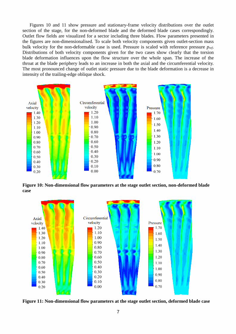
Figures 10 and 11 show pressure and stationary-frame velocity distributions over the outlet
section of the stage, for the non-deformed blade and the deformed blade cases correspondingly.
Outlet flow fields are visualized for a sector including three blades. Flow parameters presented in
the figures are non-dimensionalised. To scale both velocity components given outlet-section mass
bulk velocity for the non-deformable case is used. Pressure is scaled with reference pressure pref.
Distributions of both velocity components given for the two cases show clearly that the torsion
blade deformation influences upon the flow structure over the whole span. The increase of the
throat at the blade periphery leads to an increase in both the axial and the circumferential velocity.
The most pronounced change of outlet static pressure due to the blade deformation is a decrease in
intensity of the trailing-edge oblique shock.
Figure 10: Non-dimensional flow parameters at the stage outlet section, non-deformed blade
case
Figure 11: Non-dimensional flow parameters at the stage outlet section, deformed blade case

8
Comparison of the present computational results and experimental data (Lagun et al., 1987) is
given in Figure 12 where radial distributions of static and total pressure, pitch angle and velocities
in the absolute and rotating coordinate systems are shown. All the flow parameters given are
averaged in the circumferential direction. One can see that the blade deformation imposed has
almost a negligible effect on the distributions of static and total pressure. At that, the total pressure
is under-predicted in both the cases. From the other side, calculated distribution of the outlet static
pressure is in a good agreement with the measurement data. Note that in the CFD study performed
only an averaged level of the static pressure was prescribed. Values of the flow pitch angle
calculated for the case of non-deformed blades are close to experimental data only in a near-hub
region (approximately up to 0,3 L) and differ considerably from the measured values, up to
10 degrees, above the mid-span. Contrary to that, in the case with deformed blade, the calculated
values of the flow angle agree well with the measurement data over the entire span, except for a
peripheral region adjoining to the shroud-casing leakage gap. From Figure 12, one can conclude
also that the blade deformation imposed allows to improve noticeably the consistency of the
calculated and measured data for radial distributions of both the absolute and relative outlet
velocities.
Figure 12: Comparison of the present CFD-results and experimental data for radial
distributions of flow parameters at the stage outlet
9
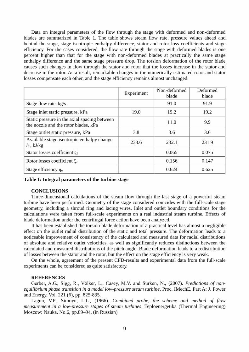
Data on integral parameters of the flow through the stage with deformed and non-deformed
blades are summarized in Table 1. The table shows steam flow rate, pressure values ahead and
behind the stage, stage isentropic enthalpy difference, stator and rotor loss coefficients and stage
efficiency. For the cases considered, the flow rate through the stage with deformed blades is one
percent higher than that for the stage with non-deformed blades at practically the same stage
enthalpy difference and the same stage pressure drop. The torsion deformation of the rotor blade
causes such changes in flow through the stator and rotor that the losses increase in the stator and
decrease in the rotor. As a result, remarkable changes in the numerically estimated rotor and stator
losses compensate each other, and the stage efficiency remains almost unchanged.
Experiment Non-deformed
blade
Deformed
blade
Stage flow rate, kg/s 91.0 91.9
Stage inlet static pressure, kPa 19.0 19.2 19.2
Static pressure in the axial spacing between
the nozzle and the rotor blades, kPa 11.0 9.9
Stage outlet static pressure, kPa 3.8 3.6 3.6
Available stage isentropic enthalpy change
h0, kJ/kg 233.6 232.1 231.9
Stator losses coefficient ζ1 0.065 0.075
Rotor losses coefficient ζ2 0.156 0.147
Stage efficiency ηu 0.624 0.625
Table 1: Integral parameters of the turbine stage
CONCLUSIONS
Three-dimensional calculations of the steam flow through the last stage of a powerful steam
turbine have been performed. Geometry of the stage considered coincides with the full-scale stage
geometry, including a shroud ring and lacing wires. Inlet and outlet boundary conditions for the
calculations were taken from full-scale experiments on a real industrial steam turbine. Effects of
blade deformation under the centrifugal force action have been analyzed.
It has been established the torsion blade deformation of a practical level has almost a negligible
effect on the outlet radial distribution of the static and total pressure. The deformation leads to a
noticeable improvement of consistency of the calculated and measured data for radial distributions
of absolute and relative outlet velocities, as well as significantly reduces distinctions between the
calculated and measured distributions of the pitch angle. Blade deformation leads to a redistribution
of losses between the stator and the rotor, but the effect on the stage efficiency is very weak.
On the whole, agreement of the present CFD-results and experimental data from the full-scale
experiments can be considered as quite satisfactory.
REFERENCES
Gerber, A.G., Sigg, R., Völker, L., Casey, M.V. and Sürken, N., (2007). Predictions of non-
equilibrium phase transition in a model low-pressure steam turbine, Proc. IMechE, Part A: J. Power
and Energy, Vol. 221 (6), pp. 825-835.
Lagun, V.P., Simoyu, L.L., (1966). Combined probe, the scheme and method of flow
measurement in a low-pressure stages of steam turbines. Teploenergetika (Thermal Engineering)
Moscow: Nauka, No.6, pp.89–94. (in Russian)

10
Lagun, V.P., Simoyu, L.L., Frumin, Yu.Z., (1971). Gasdynamic investigations of the flow path of
low pressure powerful steam turbines. In Boiler and turbine plants of power units (Doroschuk, V.E.
et al. editors) Moscow: Energia, Ch. VI, pp.157-171. (in Russian)
Lagun, V.P., Simoyu, L.L., Boitsova, E.A., Naftulin, A.B., Semenov, E.Yu., Poliakova, M.V.,
Sedlova, V.C., Pakhomov, V.A., Nezhentsev, Yu.N., Kirillov, V.I., Garkavenko, I.V. (1987).
Gasdynamic investigations of LP turbine K-1200-240 flow path carried out at Kostroma SDPP.
Registration No. 01860060188. Moscow: VTI. (in Russian)
Levin, A.V., Borishanskii, K.N., Konson, E.D., (1981). Strength and vibration of blades and
disks of steam turbines. Leningrad: Mashinostroenie, 710 p. (in Russian)
Menter, F. R., Kuntz, M., and Langtry, R., (2003). Ten Years of Industrial Experience with the
SST Turbulence Model, Turbulence, Heat and Mass Transfer 4, ed: K. Hanjalic, Y. Nagano, and M.
Tummers, Begell House, Inc., pp. 625 - 632.
Miyake, S., Yamamoto, S., Sasao, Y., Momma, K., Miyawaki, T. and Ooyama, H., (2013).
Unsteady flow effect on non-equilibrium condensation in 3-D low pressure steam turbine stages,
ASME paper GT2013-94832, 9 p.
Ryzhkov, V.K., Sorokin, N.A., Mikhailov, M.F., (1976). Steam turbine K-1200-240-3 LMZ.
Teploenergetika (Thermal Engineering) Moscow: Nauka, No.5, pp.2–7. (in Russian)
Starzmann, J., Schatz, M., Casey, M. V., Mayer, J. F., Sieverding, F., (2011). Modelling and
validation of wet steam flow in a low pressure steam turbine. ASME paper GT2011-45672, 12 p.
Wroblewski, W., Dykas, S., Gardzilewicz, Kolovratnik, M., (2009). Numerical and
experimental investigation of steam condensation in LP part of a large power turbine, Trans.
ASME, J. Fluids Eng., Vol. 131 (4), 11 p.
Yamamoto, S., Sasao, Y., Kato, H., (2010). Numerical and experimental investigations of
unsteady 3-D wet-steam flows through two-stage stator-rotor cascade channels, ASME paper
GT2010-22796, 9 p.