experience in ground improvement by dynamic compaction and
TRANSCRIPT

Missouri University of Science and Technology Missouri University of Science and Technology
Scholars' Mine Scholars' Mine
International Conference on Case Histories in Geotechnical Engineering
(1988) - Second International Conference on Case Histories in Geotechnical Engineering
03 Jun 1988, 10:30 am - 5:30 pm
Experience in Ground Improvement by Dynamic Compaction and Experience in Ground Improvement by Dynamic Compaction and
Preloading at Half Moon Bay – Saudi Arabia Preloading at Half Moon Bay – Saudi Arabia
N. Ghosh Sir William Halcrow and Partners Ltd., London, England
M. M. Tabba Saudi Hotels and Resorts Areas Company, Riyadh, Saudi Arabia
Follow this and additional works at: https://scholarsmine.mst.edu/icchge
Part of the Geotechnical Engineering Commons
Recommended Citation Recommended Citation Ghosh, N. and Tabba, M. M., "Experience in Ground Improvement by Dynamic Compaction and Preloading at Half Moon Bay – Saudi Arabia" (1988). International Conference on Case Histories in Geotechnical Engineering. 19. https://scholarsmine.mst.edu/icchge/2icchge/icchge-session5/19
This work is licensed under a Creative Commons Attribution-Noncommercial-No Derivative Works 4.0 License.
This Article - Conference proceedings is brought to you for free and open access by Scholars' Mine. It has been accepted for inclusion in International Conference on Case Histories in Geotechnical Engineering by an authorized administrator of Scholars' Mine. This work is protected by U. S. Copyright Law. Unauthorized use including reproduction for redistribution requires the permission of the copyright holder. For more information, please contact [email protected].

Proceedings: Second International Conference on Case Histories in Geotechnical Engineering, June 1-5, 1988, St. Louis, Mo., Paper No. 5.34
Experience in Ground Improvement by Dynamic Compaction and Preloading at Half Moon Bay-Saudi Arabia N. Ghosh Senior Engineer, Sir William Halcrow and Partners Ltd., London, England
M.M. Tabba Director, Saudi Hotels and Resorts Areas Company, Riyadh, Saudi Arabia
SYNOPSIS: Ground improvement techniques were used to meet the design requirements for a beach resort complex at Half Moon Bay on the Arabian Gulf. Extensive site exploration revealed upper layers consisting of loose to medium fine sand, having variable silt content. The original specification called for filling and ground improvement using Dynamic Compaction to achieve 100kN/m2 surface bearing capacity and 50% relative density at a depth of 10m. Dynamic Compaction (DC} and subsequent field testing, using full scale loading tests as well as CPT and SPT tests, proved that it was possible to achieve these requirements over most areas using dynamic compaction, however it was not suitable in a few other areas where gro.und response to DC was poor. Those areas contained silty layers and showed signs of rapid pore pressure build up under dynamic compaction, while dissipation was slow and penetration resistance remained poor. Therefore, it was decided to use pre-loading in those areas. Further testing and instrumentation showed that pre-loading was acbieving the required ground improvement.
IN'.rRODUCTION
This paper describes the case history of ground improvement at a site in the middle of Half Moon Bay some 50 km south of Al Khobar on the Arabian Gulf (Fig 1}. The site covers approximately 3.7 km2 bounded to the East by Half Moon Bay and to the South by a smaller inner bay.
Pig 1
SAUDI
ARABIA
Site Location Map - Half Moon Bay.
The development scheme undertaken in Phase I of the Half Moon Bay Beach Resort Project is to consist of two hundred and fifty one chalets surrounding the inner bay together with infrastructure, services and a recreational area in the south eastern peninsula. Various areas of investigation referred to in the following text are shown on Fig 2.
1055
\ ~\
\ \
v''W"''a lmprowKI by Dynamic Compaction --lng
HALF
MOON
BAY
ARABIAN
GULF
PIJ" 1 Finlt Plate Loading._
PIJ" 2 Second - .Loading 'Riot • 5 Settlement Guage
Pig 2 Layout of Ground Improvement Work.
Regionally, there are Sabkha deposits which cover most of the site, with intermittent caprock consisting of cemented shelly sandstone. These deposits are underlain by marine qeposits of Quaternary Age of variable thickness containing non indurated but sometime cemented deposits of silty sand with silty clay bands. The sedimentary bedrock of the Dammam formation of Eocene Age lies at depths greater than 20m. This bedrock typically consists of
Second International Conference on Case Histories in Geotechnical Engineering Missouri University of Science and Technology http://ICCHGE1984-2013.mst.edu

dolomite and limestone interbedded with marl (calcisiltite) and shale (calcilutite) (Kent, 1976).
A preliminary site exploration was carried out using dynamic probing followed by a full scale investigation which included boreholes, trial pits, standard penetration tests (SPT) and static cone penetration tests (CPT). The insitu soil conditions confirmed that buildings proposed in the main development area of the site would experience excessive settlement without treatment of the underlying, highly compressible soils. Following this, a ground improvement programme was undertaken using dynamic compaction on a surface reclaimed with dune sand up to 2m thick.
A part of the site, where the in-situ conditions prevented any improvement by dynamic compaction, was preloaded.
SITE CONDITIONS PRIOR TO GROUND TREATMENT
The ground surface originally consisted of Sabkha except in the central part where intermittent caprock was encountered. Underlying the Sabkha, fine to medium sand with traces of silt and a varying amount of shell fragments generally covers the site to a depth of 4m (Fig 3) in the peninsula and this increases to some 9m depth in the western part and in the box (Fig 2) where only traces of shell fragments were found (Fig 4). This stratum is referred to as the upper sand. Below this, extensive deposits of silt and clayey sandy silt some 6 to 7m thick are present in the peninsula (Fig 3) and some Sm were found in the western part (Fig 4). This is referred to as the intermediate silt layer. The SPT and the CPT results indicated that the upper
BH1sw G.L •.
x: 5
-a :X.
- ;c:
Description
Very loose to loose grey sandy clayey SILT
CPT Cone Resistance Kg;cm2
0 100 200
·. ·. 50 Vety dense light brown silty . : fine to medium SAND x:. • ·X
x: ·20 -:..
·22 ·-
Pig3
CPT 32
Hard grey silty clay
Typical borehole and CPT profile in the Eastern peninsula.
1056
BH 9 S~T Description
G.L
0 :{ 3 ~y ~oi~';{'N~~~HA) . ". 4 __;;c:_,..:.._.:._..:.,_.:.__.:.__
·2 5 t:'.::Jtn: ~ci'~~':,\~. · · 9 of shell fragments and silt
·4 '., · 14 ..... becoming medium dense
:::. 22
·6 ·::: 22
.. 10
·8 .:.:·: 7
Yery loose to loose grey slig'htly c'- and sandy SLT with occasional sheN fragments
CPT Cone Resistance Kg/cm2
0 100 200
CPT34
Pig 4 Typical borehole and CPT profile in the Western parts of the site.
sand and the intermediate silt strata were in a very loose to loose state except in the northern part of the finger and in some locations within the box area (Fig 2) where the upper sand layer was found to be medium dense with increasing depth. Underlying the silt stratum, sand deposits prevail across the site with a transition zone of silty sand generally some 2m thick, and this stratum was normally found to be loose to very dense. This is referred to as the lower sand layer which overlies a hard silty clay generally encountered at 19 to 20m depth.
Groundwater was found to be within a metre of the ground surface at the northernmost part of the site, but it was within 250mm in the eastern and western parts of the site.
GROUND IMPROVEMENT
The proposed construction site over 44 ha, was initially cleared by removing the Sabkha and reclaimed with a maximum of 2m of dune sand, compacted in layers by vibro compactors, to provide a surface 2m above Datum. The dynamic compaction was applied on this surface with the aim of achieving a safe bearing capacity of 100 kN/m2 at the surface and densification of the subsoil from the surface downward at least to 10m where the relative density of the soil should not be less than 50 per cent. The CPTs were us.ed to verify the improvement and also to estimate the relative density at 10m depth using Schmertmanri ( 1978) , .correlation with the cone resistance (qcl and the effective overburden pressure (p0 ) •
Dynaaic Compaction Trial
An area of the site having relatively poor soil conditions was selected for the dynamic compaction trials (Fig 2). The initial four (Trials 1 to 4) of six trials performed were
Second International Conference on Case Histories in Geotechnical Engineering Missouri University of Science and Technology http://ICCHGE1984-2013.mst.edu

carried out using a 2 x 2m, 16 tonne pounder dropping freely from a height of 20m using a 120 tonne Manitowac-crawler mounted crane; the last two trials (Trials 5 and 6) were performed with a 25m drop. Normally, 10 blows were applied to each print, except in Trial 5 where 20 blows were applied. In each trial, quality control was performed using piezometers and CPTs. Trial 1 to 4 inclusive were carried out covering grid systems from 5 to 12m either by a single pass or up to 3 passes, whereas in trials 5 and 6 only a 10m grid was used with 2 passes. However, the timing for the passes was not always controlled by the dissipation of pore pressure generated. Three hollow stem auger holes were sunk in the trial area, prior to dynamic compaction. The intermediate silt layer in a very loose state was found at 3m below Datum. The results of the trials confirmed that only the initial 5m, including the compacted fill, improved satisfactorily while responses to dynamic compaction below this level were insignificant.
During the performance of some trials (2,4,5 and 6) it was noticed that the ground water (or in some cases a dark dense odoriferous fluid) overflowed from the standpipes (some 1.5m above the surface), but on some occasions immediate falls of piezometric heads were noticed during
2
3
4
5
7
8
9
10
Fig 5
- - - Pre co..,act~on
~ Past compaction
-- Mun poet compaction
Pre-and-post dynamic compaction CPT results at Load Test l location.
1057
the course of tamping. This phenomenon might have been due to local liquefacation of the soil in the intermediate silt stratum. Subsequent monitoring showed that there was little change of these modified piezometric heads in the next six months.
Dyna.ic Compaction
Following the disappointing results from the trials, the contractor embarked on the full scale dynamic compaction programme using the same weight, 10 blows per print, 25m drop and lOrn centres starting from the north of the finger. Piezometers were installed at 9m below Datum on a 50m grid.
Considerable ground improvement was noticed in many parts of the finger and the box areas, even after the first (north of the trial area), or second passes. However, such improvement in many areas was still insufficient to meet the specified relative density of 50 per cent, to be achieved at Sm below Datum in accordance with the Schmertmann's correlation. A full scale load test was carried out to overcome this situation,and this is described in the following section. The average CPT profile obtained from this test location (Fig 5) was finally used to
Cone Resistance Kg/cm2
o.~~~._~ __ .__5•o--~~--~~--100._~--._~--~-11so
2 ...... -<_ ....,.>
---
-----------
----3 -{ ... r-~
4 ' ..... ) I
5 ', __ > _......... ,...~ r ' _ _.__.
( \ ', ( ) < ( ,-> "-..,
(> I ( ---~ ) r --- ""' compaction
'- } --- After 2nd pass Of DC
7
8
-- Alter 3rd paas of DC </ .___ \ --/ ............... --t r.--
9
10
J )
(! Fig 6 Typical pre-and-post dynamic compaction.
CPT results from Western parts of the site.
Second International Conference on Case Histories in Geotechnical Engineering Missouri University of Science and Technology http://ICCHGE1984-2013.mst.edu

approve the dynamic compaction work at the site.
In areas satisfactorily compacted using two passes of dynamic compaction, pore pressures dissipated within one month, but in those parts treated with upto four passes, where pore pressure dissipated much more slowly. Fig 6 displays typical profiles of both the pre-and post-compaction CPT results. The settlements of the ground after each pass was in the order of 200mm. After the final pass, an "ironing pass" was performed to compact the near surface soils, especially around the craters.
Pull scale plate load tests and settlement analysis
The full scale load test referred to above was carried out using a large concrete plate {4 x 4m x 0.4m thick) loaded to 150 kN/m2 pressure. The location of the first such test {Load Test ll was chosen in the box area {Fig 2), where two passes of dynamic compaction were given. The load test was carried out at 1.25m above Datum using concrete blocks as Kentledge. Fig 5 displays the results of a few post-compaction CPTs carried out prior to the load test, and a CPT profile from the original site investigation is also included. The load test commenced by placing the full load within the first 24 hour; the total settlement of Smm took place within 48 hour. The load was maintained for 19 days when no significant movement was recorded.
The plate used acted as a 4 x 4m square footing {B = 4m) and the applied pressure must have influenced the ground at least to a depth of 2B (8m) which was some 7m below Datum.
By comparing the measured settlement with that calculated as suggested in Schmertmann (1978) a value of X = 7 was evaluated (E = Xqc, where "E" is the soil deformation modulus). Schmertmann proposed that the values of X could be taken as 2.5 and 3.5 for square and long footings only with first loading case respectively. But, he quoted that if the sand has been strained by preloading or any other methods, the real settlement will probably be significantly less than predicted using values of X quoted above. Schmertmann, therefore, suggested that in such cases the values of X can be increased by a factor equal to or greater than-that would indicate by the resulting increase in qc• This apparently agrees with the results shown in Fig 5.
A second load test was performed at a location in the trial area (Fig 2) using identical arrangements except that the plate was placed at one metre above Datum. The results of this test was satisfactory, and was used to approve the work which did not meet the criteria of Load Test 1.
Relative Density
Following the encouraging result of Load Test 1, an investigation was made using SPT to assess relative density in areas where dynamic compaction work was approved on the basis of Load Test 1. Three boreholes were drilled using a hollow stem auger and SPTs were carried out at l.5m intervals using a split spoon sampler. Relative
1058
density for a corresponding blow count (N) was evaluated using the analytical expression on given in Giulani & Giulani Nicoll (1982) which incorporates effective overburden pres- sure, and these results are shown on Fig 7. Fig 7 shows that after dynamic compaction, 50 per cent relative density was generally achieved at a depth of lOrn. It is interesting to note that some low N values under small overburden pressure are within the medium dense range in the relative density scale, even though this can be classified as loose when the general descriptive terms were used.
l l
Standard Penetration Test N /300 mm
0 4 8 u re ~ ~ ~ ~ ~ ~ « ~ ~
53.: 2
4
E :E
!6
44®
8
10
"30 Description ~ l.aoee
% 0-15 15-35
e BH 1 Box South
® BH 2 Box North
• BH 3 Finger
®78
®76 .87 .116
.71 ~95 .118
83® ~92 .98
.65 ®78 .89
.52 85
54 • ®66
®49
Medium Dense Dense
35-65 65-85
Pig 7 SPT (N) blows profiles with calculated relative density values.
Pre loading
Despite the fact that dynamic compaction was successful over most of the site, quite a large part (122 ha) did not respond (Fig 2). The initial site investigation indicated that most of this area contains layer(s) 6 to 7m thick of loose to very loose silt and the groundwater, which is influenced by the tide, was found close to the original ground surface. An additional site investigation consisting of three 25m deep boreholes was carried out, with a view to predicting the time settlement under pre-loading.
.It was confirmed that no improvement of the intermediate silt layer was apparent after an initial dynamic compaction operation. Fig 8 displays an envelope of particle size distribution of this intermediate silt layer, which shows that the silt content varies between 40 and 80 per cent and the clay content is less than 10 per cent. Fig 8 also includes the grading envelopes of the upper and lower sand strata. The samples from the intermediate silt layer were mostly found to be of low to intermediate plasticity, and some were non-plastic.
Second International Conference on Case Histories in Geotechnical Engineering Missouri University of Science and Technology http://ICCHGE1984-2013.mst.edu
.!!' 60 +--+--...J----+-
~00~--~--~----~-+i ~40·~-+-+----~-+~ ,f 30~-+-+---+----+---1
10 5 0·5 0·1 005 Grain SiZe mm
Fine
0·01 0·005 0·001
SILT or CLAY
@~l Upper Sand ,Stratum [Z2J Lower Sand Stratum c::::J Intermediate Silt Layer
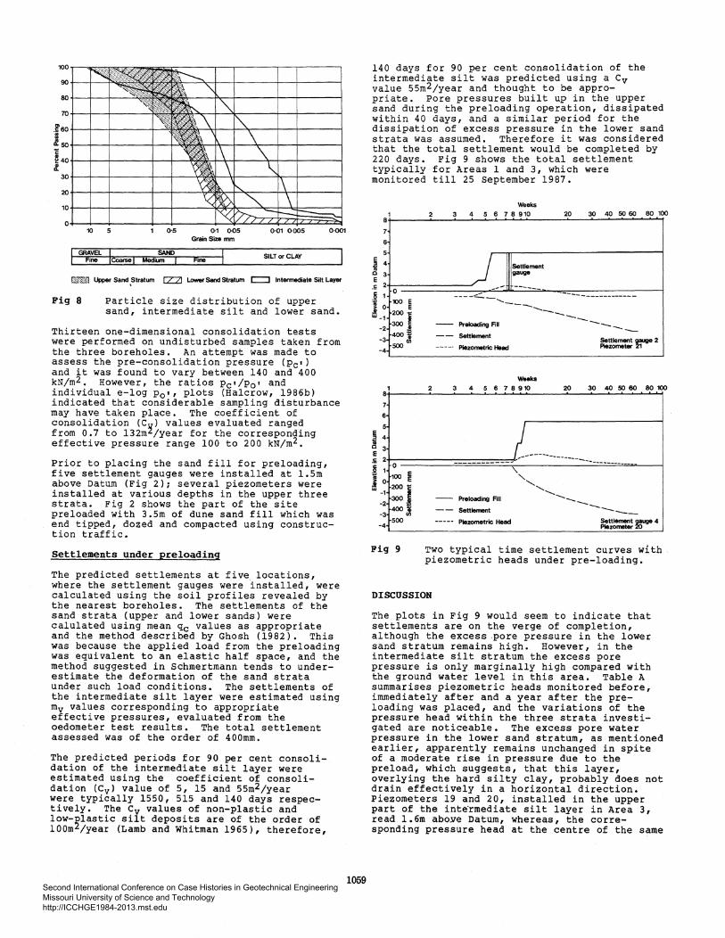
Fig 8 Particle size distribution of upper sand, intermediate silt and lower sand.
Thirteen one-dimensional consolidation tests were performed on undisturbed samples taken from the three boreholes. An attempt was made to assess the pre-consolidation pressure <Pc•l and it was found to vary between 140 and 400 kN/m2. However, the ratios Pc•/p0 • and individual e-log Po•• plots (Halcrow, 1986b) indicated that considerable sampling disturbance may have taken place. The coefficient of consolidation (C~) values evaluated ranged from 0.7 to l32m~/year for the corresponding effective pressure range 100 to 200 kN/m2.
Prior to placing the sand fill for preloading, five settlement gauges were installed at 1.5m above Datum (Fig 2); several piezometers were installed at various depths in the upper three strata. Fig 2 shows the part of the site preloaded with 3.5m of dune sand fill which was end tipped, dozed and compacted using construction traffic.
Settlements under preloading
The predicted settlements at five locations, where the settlement gauges were installed, were calculated using the soil profiles revealed by the nearest boreholes. The settlements of the sand strata (upper and lower sands) were calulated using mean qc values as appropriate and the method described by Ghosh (1982). This was because the applied load from the preloading was equivalent to an elastic half space, and the method suggested in Schmertmann tends to underestimate the deformation of the sand strata under such load conditions. The settlements of the intermediate silt layer were estimated using mv values corresponding to appropriate effective pressures, evaluated from the oedometer test results. The total settlement assessed was of the order of 400mm.
The predicted periods for 90 per cent consolidation of the intermediate silt layer were estimated using the coefficient of consolidation (Cvl value of 5, 15 and 55m2/year were typically 1550, 515 and 140 days respectively. The Cv values of non-plastic and low-~lastic silt deposits are of the order of lOOm /year (Lamb and Whitman 1965), therefore,
1059
140 days for 90 per cent consolidation of the intermediate silt was predicted using a Cv value 55m2/year and thought to be appro-priate. Pore pressures built up in the upper sand during the preloading operation, dissipated within 40 days, and a similar period for the dissipation of excess pressure in the lower sand strata was assumed. Therefore it was considered that the total settlement would be completed by 220 days. Fig 9 shows the total settlement typically for Areas 1 and 3, which were monitored till 25 September 1987.
1 8
7
6
i 4 Q 3 e .E 2
0 6 1
1 0 100 E
E w -1 200 i
-2 300G
-3 400 i soo"'
-4
1 8
7
6
5
.5 4 2! E
3
.E 2
i 0
1 E 100 0 E
w 200 1: -1
300 J -2
-3 400Jl 500
-4
Fig 9
2
2
Weeks 3 4 5 6 7 8 910
----~
Settlement gauge
--- ------ ......
20
--------.....-.. -------- Preloading Fil
-- Settlement
----- Piezometric Head
Weeks
3 4 56 78910 20
30 40 00 60 80 100
------
30 40 00 60 80 100
.. --------... ---------- - ---- - ------------
', '-, ........ ___
Preloading Fill --.. __
Settlement ----
Piezometric Head ~~= ~uge 4
Two typical time settlement curves with . piezometric heads under pre-loading.
DISCUSSION
The plots in Fig 9 would seem to indicate that settlements are on the verge of completion, although the excess pore pressure in the lower sand stratum remains high. However, in the intermediate silt stratum the excess pore pressure is only marginally high compared with the ground water level in this area. Table A summarises piezometric heads monitored before, immediately after and a year after the preloading was placed, and the variations of the pressure head within the three strata investigated are noticeable. The excess pore water pressure in the lower sand stratum, as mentioned earlier, apparently remains unchanged in spite of a moderate rise in pressure due to the preload, which suggests, that this layer, overlying the hard silty clay, probably does not drain effectively in a horizontal direction. Piezometers 19 and 20, installed in the upper part of the inte·rmediate silt layer in Area 3, read 1.6m aboye Datum, whereas, the corresponding pressure head at the centre of the same
Second International Conference on Case Histories in Geotechnical Engineering Missouri University of Science and Technology http://ICCHGE1984-2013.mst.edu

Stratum Piezo- Level of Piezometric Head (M Elv.) Description meters Installation
No. (m Elv.)
Maximum After After Recorded
Installation Preload on 25/9/87
Upper Sand 22 - 3.0 +0 .45 +1.30 +0.65 Upper Sand *23 - 3.0 +0.65* +0.95 +0.5
Intermediate 6(GKN) - 9.0 - - +0.76 Silt
II II 7(GKN) - 9.0 +1.0 +1.5 +1.08 " " 18 - 7.5 +0.65 +1.4 +0.95 II II 19 - 5.0 +1.50 +2.0 +1.38 II n 20 - 5.0 +1. 70 +2.5 +1.55 II II 21 - 4.0 +0.80 +2.0 +1.05
Lower Sand 16 - 18.0 +0.80 +1.40 +1.66 " II 17 - 14.0 +0.80 +1.60 +1.55
(a) *Fill material was placed near to piezometer 23 before the initial readings were taken.
(b) General groundwater level + 0.45m
TABLE A Piezometer Monitoring Records
layer is about one metre above Datum. Reasons. for this variation were not apparent from the site investigations.
The above evidence seems to indicate that the main factors causing failure of dynamic compaction in the eastern part of the site (Fig 4) were the shallow depth of the upper sand above a very loose, waterbound silt stratum together with the complex ground water regime.
CONCLUSIONS
1. It is clearly of prime importance to have a detailed study of the ground water regime before embarking on any ground improvement programme, and especially, when a site tains a thick layer of loose silt.
2. Dynamic compaction is a repid and economic method of ground improvement when it is applied to suitable ground conditions. Results are enhanced considerably by subsequent passes, provided that the excess pore water pressure generated due to the applied energy within the loose subsoil is allowed to dissipate. Ground conditions similar to those encountered in Area 3 are
.considered unsuitable for dynamic compaction,
3. Full scale load tests designed to meet foundation conditions are considered to be the most appropriate method of verifying ground improvement.
4. Relative density of in-situ silty sand may be assessed effectively using published analytical correlations established with SPT results.
1060
5. The settlement of footings on sand may be assessed reliably using the method due to Schmertmann, but such methods tend to underestimate the deformation of the sand under extended fill loads.
ACKNOWLEDGEMENT
The authors would like to thank the Saudi Hotels and Resort Areas Company (SHARACO), Riyadh, for permission to publish, and Mr N A Trenter, Director, Sir William Halcrow and Partners Ltd for providing valuable comments and facilities to produce this paper.
REFERENCES
Ghosh, N(l982), "Correlation of predicted and measured settlements in full scale loading on sand fill", Proc., 2nd European Symp. on Penetration Testing (ESOPT II), Amsterdam, 567-73.
Giuliani, F and F L Giuliani Nicoll (1982), "New analytical correlation between SPT, overburden pressure and relative density", Proc., Second European Symp. on Penetration Testing (ESOPT II), Amsterdam, 47-50.
Kent, P E (1976), "Middle East- The geological background", Proc., Conf. Engineering Problems Associated with Ground Conditions in the Middle East, the Geological society, London, Nov., 1-7.
Lambe, T Wand R V Whitman (1969), "Soil Mechanics", John Wiley & Sons, Inc;New York.
Second International Conference on Case Histories in Geotechnical Engineering Missouri University of Science and Technology http://ICCHGE1984-2013.mst.edu

Schmertmann, J H (1978), "Guidelines for Cone Penetration Test- Performance and Design", Report No FHWA -TS-78-209, OS Dept. of Transportation, Washington.
Sir William Halcrow & Partners (1986a), "Half Moon Bay Beach Resort Project, Interim Report on the Performance of the Dynamic compaction Carried Out at the Site", January, 1986.
Sir William Halcrow & Partners (1986b), "Half Moon Bay Beach Resort Project, Geotechnical Report for the Settlement of Subsoil Onder Preloading", October, 1986.
1061 Second International Conference on Case Histories in Geotechnical Engineering Missouri University of Science and Technology http://ICCHGE1984-2013.mst.edu