exergy analysis of the main propulsion steam …the main propulsion steam turbine is analyzed during...
TRANSCRIPT
Brodogradnja/Shipbuilding/Open access Volume 70 Number 1, 2019
59
Vedran Mrzljak
Igor Poljak
Jasna Prpić-Oršić
http://dx.doi.org/10.21278/brod70105 ISSN 0007-215X
eISSN 1845-5859
EXERGY ANALYSIS OF THE MAIN PROPULSION STEAM TURBINE
FROM MARINE PROPULSION PLANT
UDC 629.5.016:629.5.03
Original scientific paper
Summary
The paper presents exergy analysis of main propulsion steam turbine from LNG carrier
steam propulsion plant. Measurement data required for turbine exergy analysis were obtained
during the LNG carrier exploitation at three different turbine loads. Turbine cumulative
exergy destruction and exergy efficiency are directly proportional - they increase during the
increase in propulsion propeller speed (steam turbine load). Cumulative exergy destruction
and exergy efficiency amounts 2041 kW and 66.01 % at the lowest (41.78 rpm), up to the
5923 kW and 80.72 % at the highest (83.00 rpm) propulsion propeller speed. Increase in
propulsion propeller speed resulted with an increase in analyzed turbine developed power
from 3964 kW at 41.78 rpm to 24805 kW at 83.00 rpm. Analyzed turbine lost power at the
highest propulsion propeller speed is the highest and amounts 3339 kW. Steam content at the
main propulsion turbine outlet decreases during the increase in propulsion propeller speed.
Exergy flow streams can vary considerably, even for a small difference in propulsion
propeller speed. Steam turbine in land-based power plant (high power steam turbine) or in
marine steam plant (low power steam turbine) is not the component which exergy destruction
or exergy efficiency is significantly influenced by the ambient temperature change. A detail
analysis of main propulsion steam turbine from the marine steam power plant at several loads
is hard to find in the scientific and professional literature.
Key words: marine steam turbine; exergy analysis; propulsion; marine steam plant
1. Introduction
In ship propulsion nowadays, diesel engines in general (mostly slow speed diesel
engines) have a leading role [1,2], due to several significant advantages. The wide presence of
diesel engines in ship propulsion enabled the development of different numerical models for
investigation of their operating parameters [3] and for optimization of their processes [4].
Steam propulsion, in general, is only slightly present on ships, but it is still the dominant
type of propulsion for LNG (Liquefied Natural Gas) carriers [5] due to the specificity of their
operation and the transported cargo. Any steam system is usually very complex because it is
assembled from a large number of components [6]. The majority of marine steam propulsion
Vedran Mrzljak, Igor Poljak, Exergy analysis of the main propulsion steam
Jasna Prpić-Oršić turbine from marine propulsion plant
60
plant components are the same as components in conventional land-based steam power plants,
but their operation principle is much more dynamic. Usually, the marine steam propulsion
plant consists of two steam generators [7] due to safety operation and two parallel operating
turbo-generators [8] to ensure electricity supply at any time. Propulsion propeller (or more of
them) drive is ensured with main propulsion turbine [9]. Steam after expansion in turbo-
generators and main propulsion turbine goes to the main condenser [10] on liquefaction.
On water return channel to steam generators there are several devices which provide
water heating. The first of such devices is evaporator (fresh water generator) [11], the steam
marine plant component which is not required in land-based steam plants. After evaporator is
usually located sealing steam condenser [12] and two or more feed water heaters [13,14].
Between feed water heaters is located deaerator [15,16] with its dual function - feed water
heating and removal of gaseous components from feed water to reduce corrosion. On water
return channel are also mounted hot well [17] for collecting all the condensate from the
system and desuperheater. Desuperheater is a heat exchanger which is used for steam cooling
and preparation for the purpose of heating the cargo and all auxiliary systems [18]. General
marine steam propulsion plant scheme of one conventional LNG carrier can be found in [8].
At this moment, new systems for LNG carrier propulsion, which are at least partially
based on steam turbines, are under the development [19]. One of the main goals of such
propulsion systems is to reduce greenhouse gas emissions at the lowest possible level
[20,21,22]. For such complex marine propulsion systems is necessary to provide the
economic and profitability analysis [23] as well as operational risk assessment [24] in order to
minimize possible harmful consequences.
This paper presents a complete exergy analysis and exergy flow analysis of main
propulsion steam turbine from LNG carrier steam propulsion plant. Analyzed turbine has two
cylinders (high pressure and low pressure cylinder) and three steam subtractions.
Measurement data required for main propulsion turbine exergy analysis were obtained during
the LNG carrier exploitation at three different turbine loads (low load - 41.78 rpm, middle
load - 74.59 rpm and high load - 83.00 rpm).
The main propulsion steam turbine is analyzed during the harbour leaving until reaching
the cruising speed. Therefore, low turbine load (41.78 rpm) represents the beginning of ship
acceleration; middle load (74.59 rpm) is a turbine load during ship acceleration and high
turbine load at 83.00 rpm is turbine load at the ship cruising speed. Turbine high load (load at
the ship cruising speed) usually amounts around 85 % of turbine maximum (full) load because
on such turbine load specific fuel consumption is the lowest. In this particular case, the main
turbine developed power at high load (83.00 rpm) amounts 84.3 % of maximum turbine
power.
Energy and exergy analysis are widely used methods for the investigation of entire
steam power plants or its components [8,16]. Equally, such analyses can be used for the
investigation of entire ship energy systems – examples can be found in [25] for chemical
tanker or in [26] for a cruise ship. Those methods are black-box methods because such
analyses do not require knowledge of any component inner structure - the relevant are only
energy and exergy inputs and outputs of the component to obtain its efficiency and losses.
Any steam turbine energy analysis gives as a result comparison of how much real
(polytropic) steam expansion process deviates from the ideal (isentropic) steam expansion
process throughout the turbine. The comparison of these two steam expansion process allows
calculation of turbine real and ideal power, after which is calculated turbine energy losses and
energy efficiencies. So, the baseline of any steam turbine energy analysis is comparison of
real and ideal steam expansion processes, as presented for marine turbo-generators in [8].
Energy analysis does not take into account the ambient conditions in which turbine operate.
Exergy analysis of the main propulsion steam Vedran Mrzljak, Igor Poljak,
turbine from marine propulsion plant Jasna Prpić-Oršić
61
Exergy analysis of the main propulsion steam turbine at different loads will present a
change in turbine exergy efficiencies and losses during the load increase - to evaluate the
current turbine operation and identify possible problems. Analysis of exergy flows and steam
mass flows throughout the main propulsion turbine at different loads can be used as a baseline
for turbine (and entire power plant) optimization. Steam content calculation at the main
turbine outlet is commonly used for better protection of turbine blades and for increasing a
period between maintenance. Exergy analysis, unlike energy analysis, takes into account the
conditions of the ambient in which turbine operates what allows analysis of the main
propulsion steam turbine exergy efficiencies and losses at different ambient temperatures. At
the end - calculated turbine exergy destruction divided by turbine developed power at any
load (specific turbine exergy destruction) can be used for direct comparison of main marine
propulsion steam turbine with any other steam turbine.
2. Steam turbine exergy analysis
2.1 General equations for exergy analysis
Mass balance for a standard volume in steady state disregarding potential and kinetic
energy can be defined according to [27,28] with an equation:
OUTIN mm (1)
Exergy analysis of any steam plant component is based on the second law of
thermodynamics [8,29]. The exergy balance equation for a standard volume (control volume)
in steady state is [30,31]:
Dex,ININOUTOUTheat EmmPX (2) (2)
where the net exergy transfer by heat ( heatX ) at the temperature T is defined as [32,33]:
QT
TX )1( 0
heat (3) (3)
Specific exergy was defined according to [34,35]:
)()( 000 ssThh (4) (4)
The total exergy of any fluid stream (exergy power) is defined according to [36,37]:
)()( 000ex ssThhmmE (5) (5)
Exergy efficiency is also called second law efficiency or effectiveness [29,38]. In
general, it can be defined by using an equation:
inputExergy
outputExergyex (6) (6)
2.2 Main steam propulsion turbine exergy analysis
Analyzed main steam propulsion turbine is mounted in the steam propulsion power
plant of commercial LNG carrier. Main characteristics and specifications of the LNG carrier,
on which the main propulsion turbine is mounted, are presented in Table 1:
Vedran Mrzljak, Igor Poljak, Exergy analysis of the main propulsion steam
Jasna Prpić-Oršić turbine from marine propulsion plant
62
Table 1 Main characteristics and specifications of the LNG carrier
Gross tonnage 100450 tons
Dead weight tonnage 84812 tons
Overall length 288 m
Max breadth 44 m
Design draft 9.3 m
Steam generators 2 x Mitsubishi MB-4E-KS
Main propulsion turbine Mitsubishi MS40-2 (max. power 29420 kW)
Turbo-generators 2 x Shinko RGA 92-2 (max. power 3850 kW each)
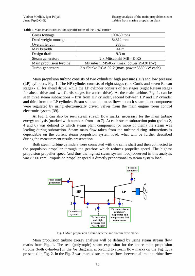
Main propulsion turbine consists of two cylinders: high pressure (HP) and low pressure
(LP) cylinders, Fig. 1. The HP cylinder consists of eight stages (one Curtis and seven Rateau
stages - all for ahead drive) while the LP cylinder consists of ten stages (eight Rateau stages
for ahead drive and two Curtis stages for astern drive). At the main turbine, Fig. 1, can be
seen three steam subtractions – first from HP cylinder, second between HP and LP cylinder
and third from the LP cylinder. Steam subtraction mass flows to each steam plant component
were regulated by using electronically driven valves from the main engine room control
electronic system [39].
At Fig. 1 can also be seen steam stream flow marks, necessary for the main turbine
exergy analysis (marked with numbers from 1 to 7). At each steam subtraction point (points 2,
4 and 6) was defined to which steam plant component (or more of them) the steam was
leading during subtraction. Steam mass flow taken from the turbine during subtractions is
dependable on the current steam propulsion system load, what will be further described
during the measurement results presentation.
Both steam turbine cylinders were connected with the same shaft and then connected to
the propulsion propeller through the gearbox which reduces propeller speed. The highest
propulsion propeller speed (and thus the highest steam system load) observed in this analysis
was 83.00 rpm. Propulsion propeller speed is directly proportional to steam system load.
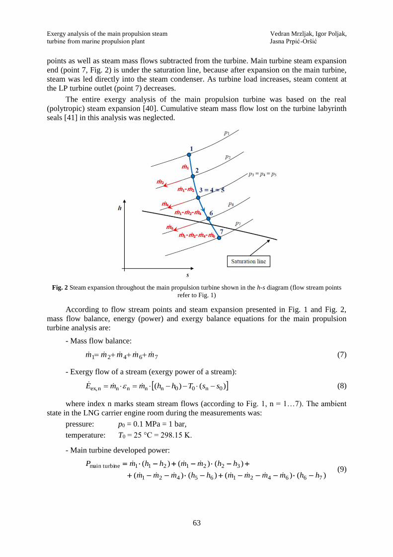
Fig. 1 Main propulsion turbine scheme and stream flow marks
Main propulsion turbine exergy analysis will be defined by using steam stream flow
marks from Fig. 1. The real (polytropic) steam expansion for the entire main propulsion
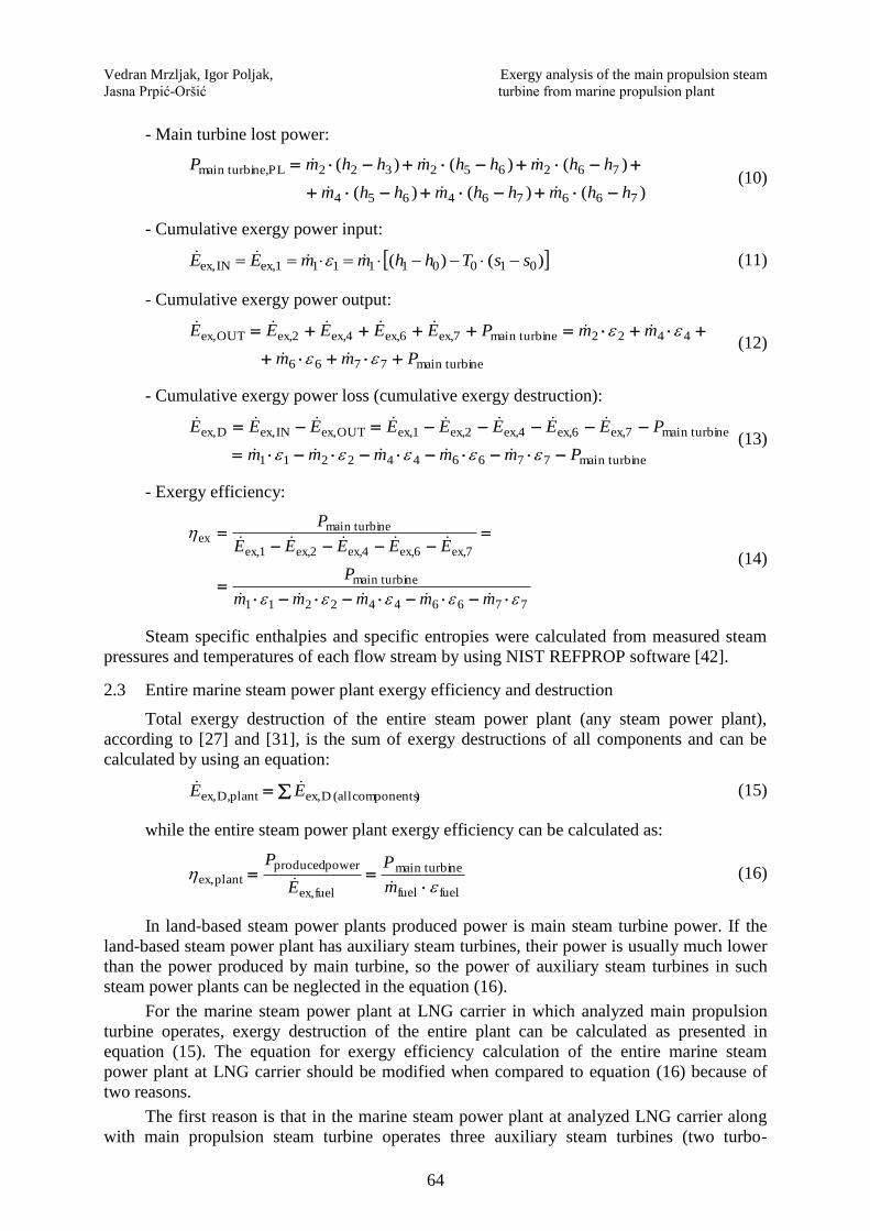
turbine (both cylinders) in the h-s diagram, according to stream flow marks on the Fig. 1, is
presented in Fig. 2. In the Fig. 2 was marked steam mass flows between all main turbine flow
Exergy analysis of the main propulsion steam Vedran Mrzljak, Igor Poljak,
turbine from marine propulsion plant Jasna Prpić-Oršić
63
points as well as steam mass flows subtracted from the turbine. Main turbine steam expansion
end (point 7, Fig. 2) is under the saturation line, because after expansion on the main turbine,
steam was led directly into the steam condenser. As turbine load increases, steam content at
the LP turbine outlet (point 7) decreases.
The entire exergy analysis of the main propulsion turbine was based on the real
(polytropic) steam expansion [40]. Cumulative steam mass flow lost on the turbine labyrinth
seals [41] in this analysis was neglected.
Fig. 2 Steam expansion throughout the main propulsion turbine shown in the h-s diagram (flow stream points
refer to Fig. 1)
According to flow stream points and steam expansion presented in Fig. 1 and Fig. 2,
mass flow balance, energy (power) and exergy balance equations for the main propulsion
turbine analysis are:
- Mass flow balance:
76421 mmmmm (7)
- Exergy flow of a stream (exergy power of a stream):
)()( 0n00nnnnnex, ssThhmmE (8)
where index n marks steam stream flows (according to Fig. 1, n = 1…7). The ambient
state in the LNG carrier engine room during the measurements was:
pressure: p0 = 0.1 MPa = 1 bar,
temperature: T0 = 25 °C = 298.15 K.
- Main turbine developed power:
)()()()(
)()()(
76642165421
3221211nemain turbi
hhmmmmhhmmm
hhmmhhmP
(9)
Vedran Mrzljak, Igor Poljak, Exergy analysis of the main propulsion steam
Jasna Prpić-Oršić turbine from marine propulsion plant
64
- Main turbine lost power:
)()()(
)()()(
766764654
762652322PLne,main turbi
hhmhhmhhm
hhmhhmhhmP
(10)
- Cumulative exergy power input:
)()( 01001111ex,1INex, ssThhmmEE (11)
- Cumulative exergy power output:
nemain turbi7766
4422nemain turbiex,7ex,6ex,4ex,2OUTex,
Pmm
mmPEEEEE
(12)
- Cumulative exergy power loss (cumulative exergy destruction):
nemain turbi7766442211
nemain turbiex,7ex,6ex,4ex,2ex,1OUTex,INex,Dex,
Pmmmmm
PEEEEEEEE
(13)
- Exergy efficiency:
7766442211
nemain turbi
ex,7ex,6ex,4ex,2ex,1
nemain turbiex
mmmmm
P
EEEEE
P
(14)
Steam specific enthalpies and specific entropies were calculated from measured steam
pressures and temperatures of each flow stream by using NIST REFPROP software [42].
2.3 Entire marine steam power plant exergy efficiency and destruction
Total exergy destruction of the entire steam power plant (any steam power plant),
according to [27] and [31], is the sum of exergy destructions of all components and can be
calculated by using an equation:
)components (all Dex,plantD,ex, EE (15)
while the entire steam power plant exergy efficiency can be calculated as:
fuelfuel
nemain turbi
fuelex,
power producedplantex,
m
P
E
P
(16)
In land-based steam power plants produced power is main steam turbine power. If the
land-based steam power plant has auxiliary steam turbines, their power is usually much lower
than the power produced by main turbine, so the power of auxiliary steam turbines in such
steam power plants can be neglected in the equation (16).
For the marine steam power plant at LNG carrier in which analyzed main propulsion
turbine operates, exergy destruction of the entire plant can be calculated as presented in
equation (15). The equation for exergy efficiency calculation of the entire marine steam
power plant at LNG carrier should be modified when compared to equation (16) because of
two reasons.
The first reason is that in the marine steam power plant at analyzed LNG carrier along
with main propulsion steam turbine operates three auxiliary steam turbines (two turbo-
Exergy analysis of the main propulsion steam Vedran Mrzljak, Igor Poljak,
turbine from marine propulsion plant Jasna Prpić-Oršić
65
generators and steam turbine for the main feed water pump drive). Cumulative power
produced by auxiliary steam turbines in some marine steam plant operating regimes can
notably influenced total produced power. The second reason of the equation (16) correction
for the analyzed marine steam power plant at LNG carrier is that both marine steam
generators simultaneously use two fuels - heavy fuel oil (HFO) and LNG. Therefore, the
equation of exergy efficiency calculation for the entire marine steam power plant at the
analyzed LNG carrier, in any load, will be:
LNGLNGHFOHFO
pump 2generator,- turbo1generator,- turbonemain turbi plantex,
mm
PPPP
(17)
For equation (17) it should be noted that power produced by the main steam turbine is
the most dominant one during the majority of marine steam power plant operation. HFO and
LNG mass flows in equation (17) are cumulative mass flows for both steam generators, while
specific exergies of both fuels can be calculated from fuel mass fractions.
Analyzed main propulsion steam turbine from LNG carrier doesn’t have steam re-
heating. Therefore, for such entire marine steam propulsion plant can be expected exergy
efficiencies between 12 % and 15 % at low main turbine load, around 20 % at middle main
turbine load and between 25 % and 30 % at high main turbine load. For comparison, similar
marine steam propulsion plant from LNG carrier where main turbine posses steam re-heating
has plant exergy efficiency of around 34 % at high main turbine load [16].
3. Main propulsion turbine measurement results and measuring equipment
Measurement results of required steam operating parameters (pressure, temperature and
mass flow) for main propulsion steam turbine, according to stream flows – Fig. 1, are
presented in relation to the propulsion propeller speed, Table 2 and Table 3. Propulsion
propeller speed is directly proportional to main propulsion turbine load, higher propulsion
propeller speed denotes a higher steam turbine load. In Table 2 are presented measurements
for HP turbine cylinder, while in Table 3 are presented measurements for LP turbine cylinder.
Table 2 Main propulsion turbine measurement results – HP cylinder
Stream flow
mark (Fig. 1)
Propulsion
propeller speed
(rpm)
Steam mass flow
at the HP turbine
entrance (kg/h)
Steam temperature
at the HP turbine
entrance (°C)
Steam pressure at
the HP turbine
entrance (MPa)
1
41.78 16605 488.0 6.190
74.59 65012 513.5 6.020
83.00 96474 500.0 5.899
Stream flow
mark (Fig. 1)
Propulsion
propeller speed
(rpm)
Steam mass flow
of HP turbine
subtraction (kg/h)
Steam temperature
of HP turbine
subtraction (°C)
Steam pressure of
HP turbine
subtraction (MPa)
2
41.78 0 - -
74.59 0 - -
83.00 3268 350.0 1.565
Stream flow
mark (Fig. 1)
Propulsion
propeller speed
(rpm)
Steam mass flow
at the HP turbine
outlet (kg/h)
Steam temperature
at the HP turbine
outlet (°C)
Steam pressure at
the HP turbine
outlet (MPa)
3
41.78 16605 243.0 0.151
74.59 65012 256.0 0.467
83.00 93206 256.0 0.593
Vedran Mrzljak, Igor Poljak, Exergy analysis of the main propulsion steam
Jasna Prpić-Oršić turbine from marine propulsion plant
66
Table 3 Main propulsion turbine measurement results – LP cylinder
Stream flow
mark (Fig. 1)
Propulsion
propeller speed
(rpm)
Subtraction steam
mass flow between
HP and LP
turbine (kg/h)
Subtraction steam
temperature
between HP and
LP turbine (°C)
Subtraction steam
pressure between
HP and LP
turbine (MPa)
4
41.78 0 - -
74.59 4690 256.0 0.467
83.00 13609 256.0 0.593
Stream flow
mark (Fig. 1)
Propulsion
propeller speed
(rpm)
Steam mass flow
at the LP turbine
entrance (kg/h)
Steam
temperature at the
LP turbine
entrance (°C)
Steam pressure at
the LP turbine
entrance (MPa)
5
41.78 16605 243.0 0.151
74.59 60322 256.0 0.467
83.00 79597 256.0 0.593
Stream flow
mark (Fig. 1)
Propulsion
propeller speed
(rpm)
Steam mass flow of
LP turbine
subtraction (kg/h)
Steam temperature
of LP turbine
subtraction (°C)
Steam pressure of
LP turbine
subtraction (MPa)
6
41.78 0 - -
74.59 2032 156.0 0.097
83.00 3355 153.0 0.121
Stream flow
mark (Fig. 1)
Propulsion
propeller speed
(rpm)
Steam mass flow at
the LP turbine
outlet (kg/h)
Steam temperature
at the LP turbine
outlet (°C)
Steam pressure at
the LP turbine
outlet (MPa)
7
41.78 16605 32.50 0.00489
74.59 58290 29.47 0.00412
83.00 76242 34.92 0.00561
Measurement results were obtained from the existing measuring equipment mounted on
both main propulsion turbine cylinders and on all steam subtraction streams. List of used
measuring equipment was presented in Table 4.
Table 4 Main propulsion turbine measuring equipment
Stream
flow mark
(Fig. 1)
Steam mass flow
(differential pressure
transmitters [43])
Steam pressure
(pressure transmitters [44])
Steam temperature
(immersion probes [45])
1 Yamatake JTD960A Yamatake JTG960A Greisinger GTF 601-Pt100
2 Yamatake JTD960A Yamatake JTG940A Greisinger GTF 601-Pt100
3 Yamatake JTD930A Yamatake JTG940A Greisinger GTF 401-Pt100
4 Yamatake JTD930A Yamatake JTG940A Greisinger GTF 401-Pt100
5 Yamatake JTD930A Yamatake JTG940A Greisinger GTF 401-Pt100
6 Yamatake JTD920A Yamatake JTG940A Greisinger GTF 401-Pt100
7 Yamatake JTD910A Yamatake JTG940A Greisinger GTF 401-Pt100
Propulsion
propeller
speed
Kyma Shaft Power Meter (KPM-PFS) [46]

Exergy analysis of the main propulsion steam Vedran Mrzljak, Igor Poljak,
turbine from marine propulsion plant Jasna Prpić-Oršić
67
4. Main propulsion turbine exergy analysis results with the discussion
Cumulative exergy power input and output of the main propulsion turbine at different
propulsion propeller speeds, calculated by using equations (11) and (12) are presented in Fig.
3. Main turbine cumulative exergy power input and output increases during the increase in
propulsion propeller speed (increase in steam system load). The difference between main
turbine cumulative exergy power input and output also increases during the increase in
propulsion propeller speed, what defines main turbine exergy power losses (exergy
destruction).
At the lowest observed propulsion propeller speed of 41.78 rpm, main turbine
cumulative exergy power input amounts 6277 kW, while cumulative exergy power output
amounts 4236 kW. At propulsion propeller speed of 74.59 rpm cumulative main turbine
exergy power input and output amounts 25205 kW and 20098 kW, while at 83.00 rpm
cumulative exergy power input and output amounts 36824 kW and 30901 kW. Presented
exergy power inputs and outputs in Fig. 3 for every propulsion propeller speed are valid for
the ambient state in the LNG carrier engine room during measurements.
Fig. 3 Main propulsion turbine cumulative exergy power input and output at different propulsion propeller
speeds - according to measurement state
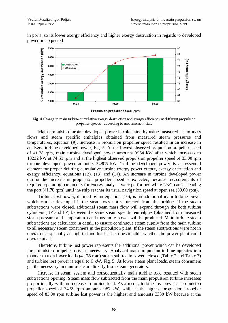
Main propulsion turbine cumulative exergy destruction and exergy efficiency are
directly proportional - both increases during the increase in propulsion propeller speed, Fig. 4.
According to equation (13), increase in main turbine cumulative exergy destruction during the
increase in turbine load is caused by a fact that cumulative exergy power input increases faster
than cumulative exergy power output. Main turbine exergy efficiency also increases during
the increase in turbine load because turbine developed power increases faster than the
difference in exergy flows between turbine inlet and outlet, equation (14).
In the observed main turbine load range, cumulative exergy destruction and exergy
efficiency amounts 2041 kW and 66.01 % at propulsion propeller speed of 41.78 rpm after
which increases to 5107 kW and 78.12 % at 74.59 rpm. At the highest observed turbine load
(at the highest observed propulsion propeller speed) cumulative turbine exergy destruction
and efficiency are the highest and amounts 5923 kW and 80.72 %.
When the analyzed marine propulsion steam turbine is compared with high power steam
turbines from land-based thermal power plants such as turbines in [47] and [48], it can be
concluded that analyzed marine turbine has higher exergy destruction in regards to developed
power, while its exergy efficiency is lower. Compared to high power steam turbines, marine
propulsion steam turbine must be much flexible in operation, especially during maneuvering
Vedran Mrzljak, Igor Poljak, Exergy analysis of the main propulsion steam
Jasna Prpić-Oršić turbine from marine propulsion plant
68
in ports, so its lower exergy efficiency and higher exergy destruction in regards to developed
power are expected.
Fig. 4 Change in main turbine cumulative exergy destruction and exergy efficiency at different propulsion
propeller speeds - according to measurement state
Main propulsion turbine developed power is calculated by using measured steam mass
flows and steam specific enthalpies obtained from measured steam pressures and
temperatures, equation (9). Increase in propulsion propeller speed resulted in an increase in
analyzed turbine developed power, Fig. 5. At the lowest observed propulsion propeller speed
of 41.78 rpm, main turbine developed power amounts 3964 kW after which increases to
18232 kW at 74.59 rpm and at the highest observed propulsion propeller speed of 83.00 rpm
turbine developed power amounts 24805 kW. Turbine developed power is an essential
element for proper defining cumulative turbine exergy power output, exergy destruction and
exergy efficiency, equations (12), (13) and (14). An increase in turbine developed power
during the increase in propulsion propeller speed is expected, because measurements of
required operating parameters for exergy analysis were performed while LNG carrier leaving
the port (41.78 rpm) until the ship reaches its usual navigation speed at open sea (83.00 rpm).
Turbine lost power, defined by an equation (10), is an additional main turbine power
which can be developed if the steam was not subtracted from the turbine. If the steam
subtractions were closed, additional steam mass flow will expand through the both turbine
cylinders (HP and LP) between the same steam specific enthalpies (obtained from measured
steam pressure and temperature) and thus more power will be produced. Main turbine steam
subtractions are calculated in detail, to ensure continuous steam supply from the main turbine
to all necessary steam consumers in the propulsion plant. If the steam subtractions were not in
operation, especially at high turbine loads, it is questionable whether the power plant could
operate at all.
Therefore, turbine lost power represents the additional power which can be developed
for propulsion propeller drive if necessary. Analyzed main propulsion turbine operates in a
manner that on lower loads (41.78 rpm) steam subtractions were closed (Table 2 and Table 3)
and turbine lost power is equal to 0 kW, Fig. 5. At lower steam plant loads, steam consumers
get the necessary amount of steam directly from steam generators.
Increase in steam system and consequentially main turbine load resulted with steam
subtractions opening. Steam mass flow subtracted from the main propulsion turbine increases
proportionally with an increase in turbine load. As a result, turbine lost power at propulsion
propeller speed of 74.59 rpm amounts 987 kW, while at the highest propulsion propeller
speed of 83.00 rpm turbine lost power is the highest and amounts 3339 kW because at the
Exergy analysis of the main propulsion steam Vedran Mrzljak, Igor Poljak,
turbine from marine propulsion plant Jasna Prpić-Oršić
69
83.00 rpm all steam subtractions are opened and the steam mass flow subtracted from the
main turbine is the highest.
Fig. 5 Main turbine developed and lost power at different propulsion propeller speeds
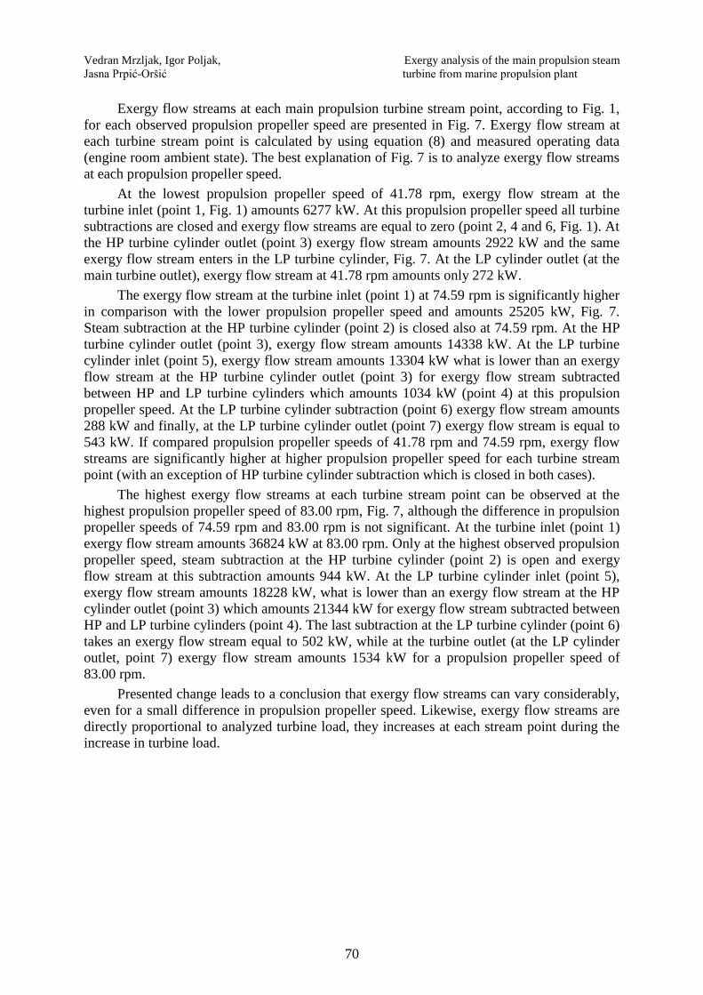
After expansion in main propulsion turbine cylinders, at the turbine outlet, steam was
led directly to the main steam condenser (point 7, Fig. 1). To be able to liquefy that steam in
the condenser, its operating parameters must be under the saturation line, in the area of
saturated steam. It is interesting to observe the change of steam content at the main turbine
outlet, according to measured data from Table 3.
At the lowest propulsion propeller speed of 41.78 rpm, steam content at the main
turbine outlet is high and amounts 98.83 %, Fig. 6. Increase in main turbine load resulted with
a decrease in steam content at the turbine outlet. At the main turbine outlet, steam content of
93.23 % was observed at propulsion propeller speed of 74.59 rpm, while at the highest load
(83.00 rpm) steam content is the lowest and amounts 92.10 %.
The majority of LNG carrier operation during the whole exploitation period can be
expected at the highest steam system load (and thus at the highest main turbine load). As
presented in Fig. 6, at the highest loads the amount of water droplets in the steam after turbine
will be the highest. High amount of water droplets will lead to increased erosion on the
turbine rotor blades, especially on the last stages of the LP turbine cylinder. Therefore, the
rotor blades at the last few stages of LP turbine are covered with special protective linings
made of hard materials (usually stellite) for wear protection in order to prolong their
replacement period [49,50].
Fig. 6 Change in steam content at LP turbine outlet during the increase in propulsion propeller speed
Vedran Mrzljak, Igor Poljak, Exergy analysis of the main propulsion steam
Jasna Prpić-Oršić turbine from marine propulsion plant
70
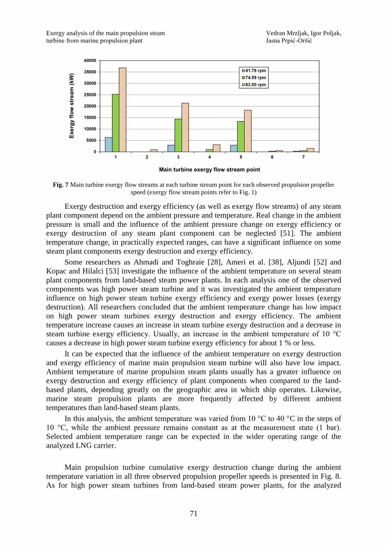
Exergy flow streams at each main propulsion turbine stream point, according to Fig. 1,
for each observed propulsion propeller speed are presented in Fig. 7. Exergy flow stream at
each turbine stream point is calculated by using equation (8) and measured operating data
(engine room ambient state). The best explanation of Fig. 7 is to analyze exergy flow streams
at each propulsion propeller speed.
At the lowest propulsion propeller speed of 41.78 rpm, exergy flow stream at the
turbine inlet (point 1, Fig. 1) amounts 6277 kW. At this propulsion propeller speed all turbine
subtractions are closed and exergy flow streams are equal to zero (point 2, 4 and 6, Fig. 1). At
the HP turbine cylinder outlet (point 3) exergy flow stream amounts 2922 kW and the same
exergy flow stream enters in the LP turbine cylinder, Fig. 7. At the LP cylinder outlet (at the
main turbine outlet), exergy flow stream at 41.78 rpm amounts only 272 kW.
The exergy flow stream at the turbine inlet (point 1) at 74.59 rpm is significantly higher
in comparison with the lower propulsion propeller speed and amounts 25205 kW, Fig. 7.
Steam subtraction at the HP turbine cylinder (point 2) is closed also at 74.59 rpm. At the HP
turbine cylinder outlet (point 3), exergy flow stream amounts 14338 kW. At the LP turbine
cylinder inlet (point 5), exergy flow stream amounts 13304 kW what is lower than an exergy
flow stream at the HP turbine cylinder outlet (point 3) for exergy flow stream subtracted
between HP and LP turbine cylinders which amounts 1034 kW (point 4) at this propulsion
propeller speed. At the LP turbine cylinder subtraction (point 6) exergy flow stream amounts
288 kW and finally, at the LP turbine cylinder outlet (point 7) exergy flow stream is equal to
543 kW. If compared propulsion propeller speeds of 41.78 rpm and 74.59 rpm, exergy flow
streams are significantly higher at higher propulsion propeller speed for each turbine stream
point (with an exception of HP turbine cylinder subtraction which is closed in both cases).
The highest exergy flow streams at each turbine stream point can be observed at the
highest propulsion propeller speed of 83.00 rpm, Fig. 7, although the difference in propulsion
propeller speeds of 74.59 rpm and 83.00 rpm is not significant. At the turbine inlet (point 1)
exergy flow stream amounts 36824 kW at 83.00 rpm. Only at the highest observed propulsion
propeller speed, steam subtraction at the HP turbine cylinder (point 2) is open and exergy
flow stream at this subtraction amounts 944 kW. At the LP turbine cylinder inlet (point 5),
exergy flow stream amounts 18228 kW, what is lower than an exergy flow stream at the HP
cylinder outlet (point 3) which amounts 21344 kW for exergy flow stream subtracted between
HP and LP turbine cylinders (point 4). The last subtraction at the LP turbine cylinder (point 6)
takes an exergy flow stream equal to 502 kW, while at the turbine outlet (at the LP cylinder
outlet, point 7) exergy flow stream amounts 1534 kW for a propulsion propeller speed of
83.00 rpm.
Presented change leads to a conclusion that exergy flow streams can vary considerably,
even for a small difference in propulsion propeller speed. Likewise, exergy flow streams are
directly proportional to analyzed turbine load, they increases at each stream point during the
increase in turbine load.
Exergy analysis of the main propulsion steam Vedran Mrzljak, Igor Poljak,
turbine from marine propulsion plant Jasna Prpić-Oršić
71
Fig. 7 Main turbine exergy flow streams at each turbine stream point for each observed propulsion propeller
speed (exergy flow stream points refer to Fig. 1)
Exergy destruction and exergy efficiency (as well as exergy flow streams) of any steam
plant component depend on the ambient pressure and temperature. Real change in the ambient
pressure is small and the influence of the ambient pressure change on exergy efficiency or
exergy destruction of any steam plant component can be neglected [51]. The ambient
temperature change, in practically expected ranges, can have a significant influence on some
steam plant components exergy destruction and exergy efficiency.
Some researchers as Ahmadi and Toghraie [28], Ameri et al. [38], Aljundi [52] and
Kopac and Hilalci [53] investigate the influence of the ambient temperature on several steam
plant components from land-based steam power plants. In each analysis one of the observed
components was high power steam turbine and it was investigated the ambient temperature
influence on high power steam turbine exergy efficiency and exergy power losses (exergy
destruction). All researchers concluded that the ambient temperature change has low impact
on high power steam turbines exergy destruction and exergy efficiency. The ambient
temperature increase causes an increase in steam turbine exergy destruction and a decrease in
steam turbine exergy efficiency. Usually, an increase in the ambient temperature of 10 °C
causes a decrease in high power steam turbine exergy efficiency for about 1 % or less.
It can be expected that the influence of the ambient temperature on exergy destruction
and exergy efficiency of marine main propulsion steam turbine will also have low impact.
Ambient temperature of marine propulsion steam plants usually has a greater influence on
exergy destruction and exergy efficiency of plant components when compared to the land-
based plants, depending greatly on the geographic area in which ship operates. Likewise,
marine steam propulsion plants are more frequently affected by different ambient
temperatures than land-based steam plants.
In this analysis, the ambient temperature was varied from 10 °C to 40 °C in the steps of
10 °C, while the ambient pressure remains constant as at the measurement state (1 bar).
Selected ambient temperature range can be expected in the wider operating range of the
analyzed LNG carrier.
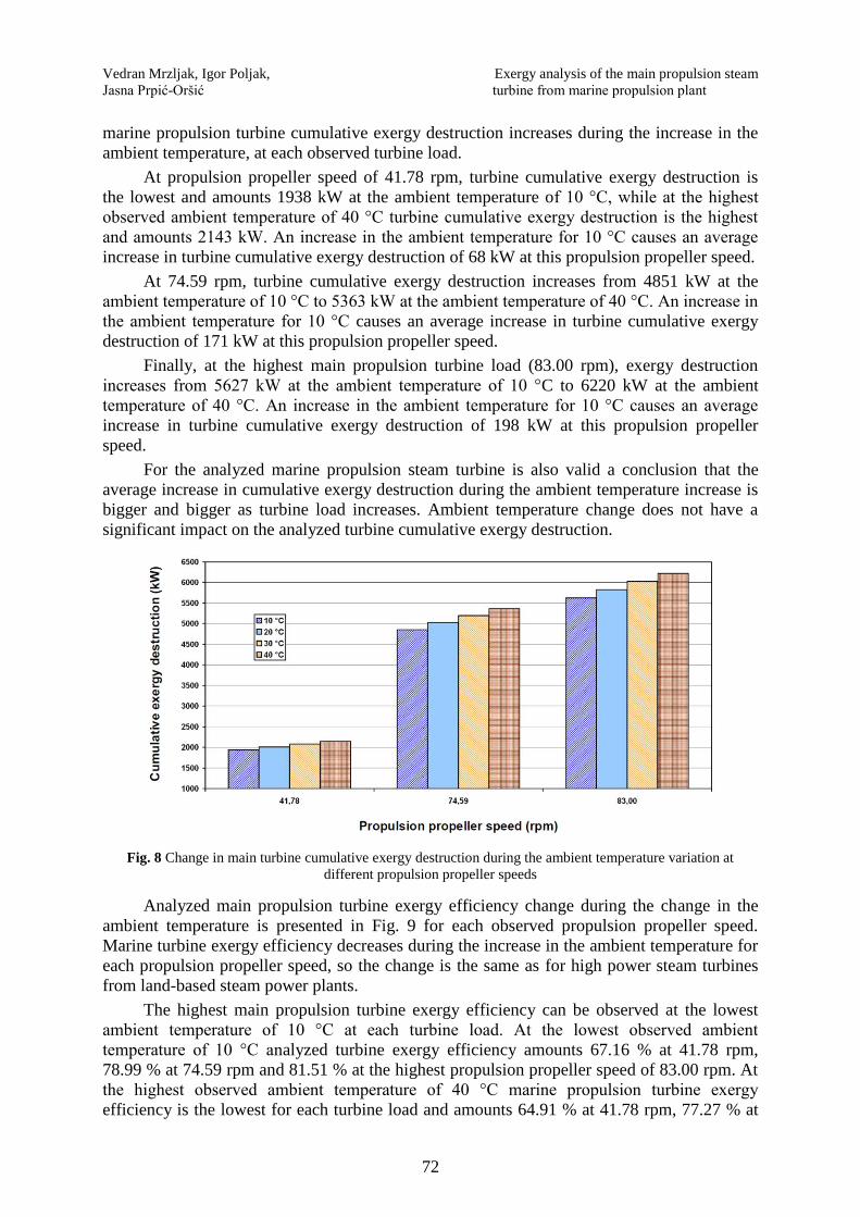
Main propulsion turbine cumulative exergy destruction change during the ambient
temperature variation in all three observed propulsion propeller speeds is presented in Fig. 8.
As for high power steam turbines from land-based steam power plants, for the analyzed
Vedran Mrzljak, Igor Poljak, Exergy analysis of the main propulsion steam
Jasna Prpić-Oršić turbine from marine propulsion plant
72
marine propulsion turbine cumulative exergy destruction increases during the increase in the
ambient temperature, at each observed turbine load.
At propulsion propeller speed of 41.78 rpm, turbine cumulative exergy destruction is
the lowest and amounts 1938 kW at the ambient temperature of 10 °C, while at the highest
observed ambient temperature of 40 °C turbine cumulative exergy destruction is the highest
and amounts 2143 kW. An increase in the ambient temperature for 10 °C causes an average
increase in turbine cumulative exergy destruction of 68 kW at this propulsion propeller speed.
At 74.59 rpm, turbine cumulative exergy destruction increases from 4851 kW at the
ambient temperature of 10 °C to 5363 kW at the ambient temperature of 40 °C. An increase in
the ambient temperature for 10 °C causes an average increase in turbine cumulative exergy
destruction of 171 kW at this propulsion propeller speed.
Finally, at the highest main propulsion turbine load (83.00 rpm), exergy destruction
increases from 5627 kW at the ambient temperature of 10 °C to 6220 kW at the ambient
temperature of 40 °C. An increase in the ambient temperature for 10 °C causes an average
increase in turbine cumulative exergy destruction of 198 kW at this propulsion propeller
speed.
For the analyzed marine propulsion steam turbine is also valid a conclusion that the
average increase in cumulative exergy destruction during the ambient temperature increase is
bigger and bigger as turbine load increases. Ambient temperature change does not have a
significant impact on the analyzed turbine cumulative exergy destruction.
Fig. 8 Change in main turbine cumulative exergy destruction during the ambient temperature variation at
different propulsion propeller speeds
Analyzed main propulsion turbine exergy efficiency change during the change in the
ambient temperature is presented in Fig. 9 for each observed propulsion propeller speed.
Marine turbine exergy efficiency decreases during the increase in the ambient temperature for
each propulsion propeller speed, so the change is the same as for high power steam turbines
from land-based steam power plants.
The highest main propulsion turbine exergy efficiency can be observed at the lowest
ambient temperature of 10 °C at each turbine load. At the lowest observed ambient
temperature of 10 °C analyzed turbine exergy efficiency amounts 67.16 % at 41.78 rpm,
78.99 % at 74.59 rpm and 81.51 % at the highest propulsion propeller speed of 83.00 rpm. At
the highest observed ambient temperature of 40 °C marine propulsion turbine exergy
efficiency is the lowest for each turbine load and amounts 64.91 % at 41.78 rpm, 77.27 % at

Exergy analysis of the main propulsion steam Vedran Mrzljak, Igor Poljak,
turbine from marine propulsion plant Jasna Prpić-Oršić
73
74.59 rpm and 79.95 % at 83.00 rpm. An increase in the ambient temperature for 10 °C
causes average decrease in marine propulsion turbine exergy efficiency of 0.75 % at 41.78
rpm, 0.57 % at 74.59 rpm and 0.52 % at 83.00 rpm.
For the analyzed marine steam turbine is valid a conclusion that the average decrease in
exergy efficiency during the ambient temperature increase is as lower as turbine load
increases. The ambient temperature change does not have significant impact also on the
marine propulsion turbine exergy efficiency.
Fig. 9 Change in main turbine exergy efficiency during the ambient temperature variation at different propulsion
propeller speeds
5. Conclusion
This paper presents an exergy analysis of main propulsion steam turbine from LNG
carrier steam propulsion plant at three different turbine loads (low load - 41.78 rpm, middle
load - 74.59 rpm and high load - 83.00 rpm). Analyzed turbine cumulative exergy destruction
and exergy efficiency are directly proportional. The lowest turbine cumulative exergy
destruction and exergy efficiency amounts 2041 kW and 66.01 % at propulsion propeller
speed of 41.78 rpm, while the highest cumulative exergy destruction and exergy efficiency
amounts 5923 kW and 80.72 % at 83.00 rpm. The analyzed marine steam turbine has higher
cumulative exergy destruction in regards to developed power and lower exergy efficiency
when compared with high power steam turbines from land-based thermal power plants.
Turbine lost power is defined with steam mass flows subtracted from the turbine and
represents the additional power which can be developed for propulsion propeller drive if
necessary. Analyzed turbine lost power at the highest propulsion propeller speed of 83.00 rpm
is the highest and amounts 3339 kW. Steam content at the main propulsion turbine outlet
(main condenser inlet) decreases during the increase in propulsion propeller speed. Analyzed
turbine exergy flow streams can vary considerably, even for a small difference in propulsion
propeller speed. The ambient temperature change does not affect significantly exergy
efficiency or destruction of main marine propulsion steam turbine - what is an identical
conclusion as for high power steam turbines from land-based steam power plants.
This analysis presented that LNG carrier crew should avoid running at partial main
turbine loads during a major period of time - main turbine exergy efficiency significantly
decreases at partial loads. Steam subtractions opening and turbine lost power at high loads
leads to a possibility of turbine optimization. During the significant ambient temperature
increase (for example summer operation in the Persian Gulf), the main propulsion steam
Vedran Mrzljak, Igor Poljak, Exergy analysis of the main propulsion steam
Jasna Prpić-Oršić turbine from marine propulsion plant
74
turbine is not the component for which can be expected notable decrease in efficiency or
increase in losses.
Acknowledgment
The authors would like to extend their appreciations to the main ship-owner office for
conceding measuring equipment and for all help during the exploitation measurements. A
retired professor Vladimir Medica, Faculty of Engineering, University of Rijeka is gratefully
acknowledged for helpful suggestions and discussions. This work has been fully supported by
the Croatian Science Foundation under the project IP-2018-01-3739.
NOMENCLATURE Greek symbols:
specific exergy, kJ/kg
Abbreviations: efficiency, -
HFO Heavy Fuel Oil
HP High Pressure Subscripts:
LNG Liquefied Natural Gas 0 ambient state
LP Low Pressure D destruction
ex exergy
Latin Symbols: IN inlet (input)
E stream flow power, kJ/s OUT outlet (output)
h specific enthalpy, kJ/kg PL power lost
m mass flow rate, kg/s or kg/h
p pressure, MPa
P power, kJ/s
Q heat transfer, kJ/s
s specific entropy, kJ/kg·K
heatX heat exergy transfer, kJ/s
T temperature, °C or K
REFERENCES
[1] Senčić, T., Račić, N., Franković, B.: Influence of Low-Speed Marine Diesel Engine Settings on Waste
Heat Availability, Shipbuilding: Theory and Practice of Naval Architecture, Marine Engineering and
Ocean Engineering Vol. 63., No. 4, p. 329-335, 2012. (UDC 621.436:629.5)
[2] Zhao, F., Yang, W., Tan, W. W., Yu, W., Yang, J., Chou, S. K.: Power management of vessel propulsion
system for thrust efficiency and emissions mitigation, Applied Energy 161, p. 124–132, 2016.
https://doi.org/10.1016/j.apenergy.2015.10.022
[3] Mrzljak, V., Medica, V., Bukovac, O.: Volume agglomeration process in quasi-dimensional direct
injection diesel engine numerical model, Energy 115, p. 658-667, 2016.
https://doi.org/10.1016/j.energy.2016.09.055
[4] Bukovac, O., Medica, V., Mrzljak, V.: Steady state performances analysis of modern marine two-stroke
low speed diesel engine using MLP neural network model, Shipbuilding: Theory and Practice of Naval
Architecture, Marine Engineering and Ocean Engineering Vol. 66., No. 4, p. 57-70, 2015.
(UDC 629.54:621.436.13:519.6)
Exergy analysis of the main propulsion steam Vedran Mrzljak, Igor Poljak,
turbine from marine propulsion plant Jasna Prpić-Oršić
75
[5] Attah, E. E., Bucknall, R.: An analysis of the energy efficiency of LNG ships powering options using the
EEDI, Ocean Engineering 110, Part B, p. 62–74, 2015. (doi:10.1016/j.oceaneng.2015.09.040)
[6] Fernández, I. A., Gómez, M. R., Gómez, J. R., Insua, A. A. B.: Review of propulsion systems on LNG
carriers, Renewable and Sustainable Energy Reviews 67, p. 1395–1411, 2017.
https://doi.org/10.1016/j.rser.2016.09.095
[7] Mrzljak, V., Poljak, I., Medica-Viola, V.: Dual fuel consumption and efficiency of marine steam
generators for the propulsion of LNG carrier, Applied Thermal Engineering, 119, p. 331–346, 2017.
https://doi.org/10.1016/j.applthermaleng.2017.03.078
[8] Mrzljak, V., Poljak, I., Mrakovčić, T.: Energy and exergy analysis of the turbo-generators and steam
turbine for the main feed water pump drive on LNG carrier, Energy Conversion and Management, 140, p.
307–323, 2017. https://doi.org/10.1016/j.enconman.2017.03.007
[9] Taylor, D. A.: Introduction to Marine Engineering, Elsevier Butterworth-Heinemann, 1998.
[10] Medica-Viola, V., Pavković, B., Mrzljak, V.: Numerical model for on-condition monitoring of condenser
in coal-fired power plants, International Journal of Heat and Mass Transfer 117, p. 912–923, 2018.
https://doi.org/10.1016/j.ijheatmasstransfer.2017.10.047
[11] Baawain, M., Choudri, B. S., Ahmed, M., Purnama, A.: Recent Progress in Desalination, Environmental
and Marine Outfall Systems, Springer International Publishing Switzerland, 2015.
https://doi.org/10.1007/978-3-319-19123-2
[12] Mrzljak, V., Poljak, I., Medica-Viola, V.: Energy and Exergy Efficiency Analysis of Sealing Steam
Condenser in Propulsion System of LNG Carrier, Our Sea, International Journal of Maritime Science &
Technology, Vol. 64., No. 1, p. 20-25, 2017. https://doi.org/10.17818/NM/2017/1.4
[13] Mrzljak, V., Poljak, I., Medica-Viola, V.: Efficiency and losses analysis of low-pressure feed water heater
in steam propulsion system during ship maneuvering period, Scientific Journal of Maritime Research
Vol. 30., No. 2, p. 133-140, 2016. https://doi.org/10.31217/p.30.2.6
[14] Mrzljak, V., Poljak, I., Medica-Viola, V.: Thermodynamical analysis of high-pressure feed water heater
in steam propulsion system during exploitation, Shipbuilding: Theory and Practice of Naval Architecture,
Marine Engineering and Ocean Engineering Vol. 68., No. 2, p. 45-61, 2017.
https://doi.org/10.21278/brod68204
[15] Moran M., Shapiro H., Boettner, D. D., Bailey, M. B.: Fundamentals of engineering thermodynamics,
Seventh edition, John Wiley and Sons, Inc., 2011.
[16] Koroglu, T., Sogut, O. S.: Conventional and Advanced Exergy Analyses of a Marine Steam Power Plant,
Energy 163, p. 392-403, 2018. https://doi.org/10.1016/j.energy.2018.08.119
[17] Cengel Y., Boles M.: Thermodynamics an engineering approach, Eighth edition, McGraw-Hill
Education, 2015.
[18] Sutton, I.: Plant Design and Operations, Elsevier Inc., 2015.
[19] Chang, D., Rhee, T., Nam, K., Chang, K., Lee, D., Jeong, S.: A study on availability and safety of new
propulsion systems for LNG carriers, Reliability Engineering and System Safety 93, p. 1877– 1885,
2008. https://doi.org/10.1016/j.ress.2008.03.013
[20] Schinas, O., Butler, M.: Feasibility and commercial considerations of LNG-fueled ships, Ocean
Engineering 122, p. 84–96, 2016. https://doi.org/10.1016/j.oceaneng.2016.04.031
[21] Senary, K., Tawfik, A., Hegazy, E., Ali, A.: Development of a waste heat recovery system onboard LNG
carrier to meet IMO regulations, Alexandria Engineering Journal 55, Issue 3, p. 1951–1960, 2016.
https://doi.org/10.1016/j.aej.2016.07.027
[22] Ammar, N. R., Seddiek, I. S.: Eco-environmental analysis of ship emission control methods: Case study
RO-RO cargo vessel, Ocean Engineering 137, p. 166–173, 2017.
https://doi.org/10.1016/j.oceaneng.2017.03.052
[23] Raj, R., Ghandehariun, S., Kumar, A., Geng, J., Ma, L.: A techno-economic study of shipping LNG to the
Asia-Pacific from Western Canada by LNG carrier, Journal of Natural Gas Science and Engineering 34,
p. 979–992, 2016. https://doi.org/10.1016/j.jngse.2016.07.024
[24] Vanem, E., Antao, P., Østvik, I., Del Castillo de Comas, F.: Analysing the risk of LNG carrier operations,
Reliability Engineering and System Safety 93, p. 1328–1344, 2008.
https://doi.org/10.1016/j.ress.2007.07.007
[25] Baldi, F., Johnson, H., Gabrielii, C., Andersson, K.: Energy and Exergy Analysis of Ship Energy Systems
– The Case study of a Chemical Tanker, International Journal of Thermodynamics 18 (2), p. 82-93, 2015.
(doi:10.5541/ijot.70299)
Vedran Mrzljak, Igor Poljak, Exergy analysis of the main propulsion steam
Jasna Prpić-Oršić turbine from marine propulsion plant
76
[26] Baldi, F., Ahlgren, F., Van Nguyen, T., Thern, M., Andersson, K.: Energy and Exergy Analysis of a
Cruise Ship, Energies 2018, 11, 2508 https://doi.org/10.3390/en11102508
[27] Erdem, H.H., Akkaya, A.V., Cetin, B., Dagdas, A., Sevilgen, S.H., Sahin, B., Teke, I., Gungor, C., Atas,
S.: Comparative energetic and exergetic performance analyses for coal-fired thermal power plants in
Turkey, International Journal of Thermal Sciences, 48, p. 2179–2186, 2009.
https://doi.org/10.1016/j.ijthermalsci.2009.03.007
[28] Ahmadi, G. R., Toghraie, D.: Energy and exergy analysis of Montazeri Steam Power Plant in Iran,
Renewable and Sustainable Energy Reviews, 56, p. 454–463, 2016.
https://doi.org/10.1016/j.rser.2015.11.074
[29] Kanoğlu, M., Çengel, Y.A., Dincer, I.: Efficiency Evaluation of Energy Systems, Springer Briefs in
Energy, Springer, 2012. https://doi.org/10.1007/978-1-4614-2242-6
[30] Mrzljak, V., Poljak, I., Žarković, B.: Exergy Analysis of Steam Pressure Reduction Valve in Marine
Propulsion Plant on Conventional LNG Carrier, International Journal of Maritime Science &
Technology "Our Sea" 65(1), p. 24-31, 2018. https://doi.org/10.17818/NM/2018/1.4
[31] Ahmadi, G., Toghraie, D., Azimian, A., Ali Akbari, O.: Evaluation of synchronous execution of full
repowering and solar assisting in a 200 MW steam power plant, a case study, Applied Thermal
Engineering, 112, p. 111–123, 2017. https://doi.org/10.1016/j.applthermaleng.2016.10.083
[32] Hafdhi, F., Khir, T., Ben Yahyia, A., Ben Brahim, A.: Energetic and exergetic analysis of a steam turbine
power plant in an existing phosphoric acid factory, Energy Conversion and Management, 106, p. 1230–
1241, 2015. https://doi.org/10.1016/j.enconman.2015.10.044
[33] Jokandan, M.J., Aghbashlo, M., Mohtasebi, S.S.: Comprehensive exergy analysis of an industrial-scale
yogurt production plant, Energy 93, p. 1832-1851, 2015. https://doi.org/10.1016/j.energy.2015.10.003
[34] Tan, H., Shan, S., Nie, Y., Zhao, Q.: A new boil-off gas re-liquefaction system for LNG carriers based on
dual mixed refrigerant cycle, Cryogenics 92, p. 84–92, 2018.
https://doi.org/10.1016/j.cryogenics.2018.04.009
[35] Orović, J., Mrzljak, V., Poljak, I.: Efficiency and Losses Analysis of Steam Air Heater from Marine Steam
Propulsion Plant, Energies 2018, 11, 3019 https://doi.org/10.3390/en11113019
[36] Taner, T., Sivrioglu, M.: Energy-exergy analysis and optimisation of a model sugar factory in Turkey,
Energy, 93, p. 641-654, 2015. https://doi.org/10.1016/j.energy.2015.09.007
[37] Elsafi, A. M.: Exergy and exergoeconomic analysis of sustainable direct steam generation solar power
plants, Energy Conversion and Management 103, p. 338–347, 2015.
https://doi.org/10.1016/j.enconman.2015.06.066
[38] Ameri, M., Ahmadi, P., Hamidi, A.: Energy, exergy and exergoeconomic analysis of a steam power
plant: A case study, International Journal of Energy Research 33, p. 499–512, 2009.
https://doi.org/10.1002/er.1495
[39] Marine Steam Turbine MS40-2 - Instruction Book For Marine Turbine Unit, HYUNDAI-MITSUBISHI,
HYUNDAI HEAVY INDUSTRIES CO., LTD., ULSAN, KOREA, 2004., internal ship documentation
[40] Mrzljak, V., Senčić, T., Žarković, B.: Turbogenerator Steam Turbine Variation in Developed Power:
Analysis of Exergy Efficiency and Exergy Destruction Change, Modelling and Simulation in Engineering
2018. https://doi.org/10.1155/2018/2945325
[41] Cangioli, F., Chatterton, S., Pennacchi, P., Nettis, L., Ciuchicchi, L.: Thermo-elasto bulk-flow model for
labyrinth seals in steam turbines, Tribology International 119, p. 359-371, 2018.
https://doi.org/10.1016/j.triboint.2017.11.016
[42] Lemmon, E. W., Huber, M. L., McLinden, M. O.: NIST Reference Fluid Thermodynamic and Transport
Properties-REFPROP, Version 9.0, User’s Guide, Colorado, 2010.
[43] http://www.krtproduct.com (accessed: 09.01.2018)
[44] http://www.industriascontrolpro.com (accessed: 09.01.2018)
[45] https://www.greisinger.de (accessed: 05.01.2018)
[46] https://www.kyma.no (accessed: 05.01.2018)
[47] Mitrović, D., Živković, D., Laković, M. S.: Energy and Exergy Analysis of a 348.5 MW Steam Power
Plant, Energy Sources, Part A, 32, p. 1016–1027, 2010. https://doi.org/10.1080/15567030903097012
[48] Adibhatla, S., Kaushik, S. C.: Energy and exergy analysis of a super critical thermal power plant at
various load conditions under constant and pure sliding pressure operation, Applied Thermal
Engineering, 73, p. 51-65, 2014. https://doi.org/10.1016/j.applthermaleng.2014.07.030
Exergy analysis of the main propulsion steam Vedran Mrzljak, Igor Poljak,
turbine from marine propulsion plant Jasna Prpić-Oršić
77
[49] Tadashi, T.: Advances in Steam Turbines for Modern Power Plants, Woodhead Publishing, Elsevier Ltd.,
2017.
[50] Baran, J.: Redesign of steam turbine rotor blades and rotor packages – Environmental analysis within
systematic eco-design approach, Energy Conversion and Management 116, p. 18–31, 2016.
https://doi.org/10.1016/j.enconman.2016.02.067
[51] Kaushik, S. C., Reddy, V. S., Tyagi, S. K.: Energy and exergy analyses of thermal power plants: A
review, Renewable and Sustainable Energy Reviews 15, p. 1857–1872, 2011.
https://doi.org/10.1016/j.rser.2010.12.007
[52] Aljundi, I. H.: Energy and exergy analysis of a steam power plant in Jordan, Applied Thermal
Engineering 29, p. 324–328, 2009. https://doi.org/10.1016/j.applthermaleng.2008.02.029
[53] Kopac, M., Hilalci, A.: Effect of ambient temperature on the efficiency of the regenerative and reheat
Catalagzi power plant in Turkey, Applied Thermal Engineering 27, p. 1377–1385, 2007.
https://doi.org/10.1016/j.applthermaleng.2006.10.029
Submitted: 26.01.2018.
Accepted: 15.01.2019.
Vedran Mrzljak, [email protected]
Faculty of Engineering, University of Rijeka, Vukovarska 58, 51000 Rijeka, Croatia
Igor Poljak, [email protected]
Department of maritime sciences, University of Zadar, Mihovila Pavlinovića 1,
23000 Zadar, Croatia
Jasna Prpić-Oršić, [email protected]
Faculty of Engineering, University of Rijeka, Vukovarska 58, 51000 Rijeka, Croatia