exercises on voltage, capacitance and circuits exercise 1 ...pbsiegel/supnotes/exer1332.pdf ·...
TRANSCRIPT

Exercises on Voltage, Capacitance and Circuits
Exercise 1.1Instead of buying a capacitor, you decide to make one. Your capacitor consists oftwo circular metal plates, each with a radius of 5 cm. The plates are parallel to eachother and separated by a distance of 1 mm. You connect a 9 volt battery acrossthe plates. Find: the capacitance of the capacitor, the charge on each plate and theexcess number of electrons on the negative plate.
You have made a simple parallel plate capacitor. The capacitance is equal toC = ε0A/d:
C = ε0A
d
= (8.85× 10⁻¹²)π(0.05)2
0.001= 6.95× 10⁻¹¹ F
To find the charge on each plate, we use the property of capacitance, Q = CV :
Q = CV
Q = (6.95× 10⁻¹¹)(9)
Q = 6.25× 10⁻¹⁰ C
To find the number of electrons N on the negative plate, we use the fact that thecharge on an electron is 1.6× 10⁻¹⁹ Coulombs:
N =6.25× 10⁻¹⁰
1.6× 10⁻¹⁹≈ 3.91× 10⁹ (1)
Even though the capacitance and net charge is small, it amounts to a transfer ofnearly four billion electrons.
Exercise 1.2You decide to make another capacitor as shown in the figure. You start with two par-allel conducting plates, of area A. Then you place another conductor in the middlethat is a thick plate of thickness d. The top of the thick plate is a distance a from
1
2
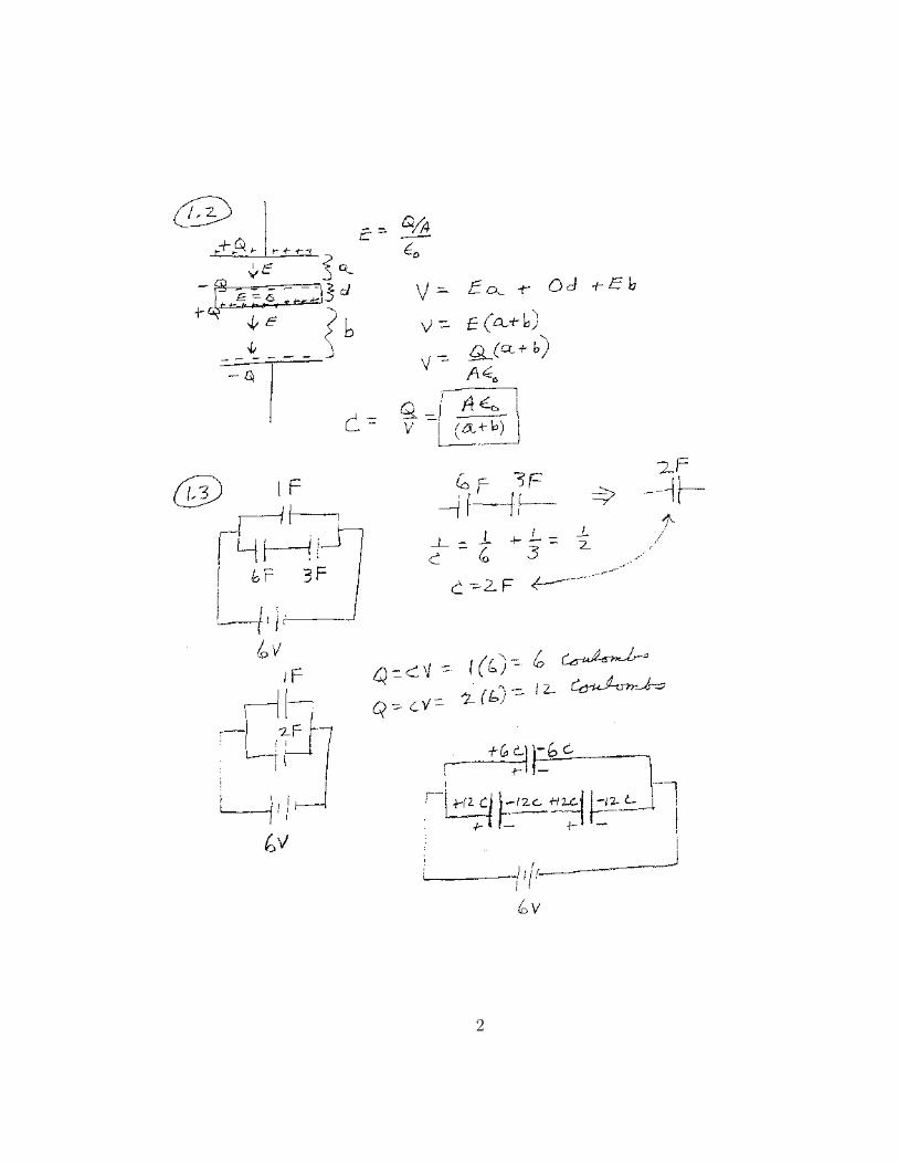
the top plate and the bottom of the thick plate is a distance b from the bottom plate.What is the capacitance of your capacitor in terms of A, a, b, d, and ε0?
To find the capacitance of a set of conductors, one can first put a charge of +Q onone plate and a charge of −Q on the other. Then determine the electric field betweenthe conductors and integrate to find the voltage difference. Then C = Q/V . Place+Q on the top plate and −Q on the bottom plate. An electric field is produce insidethe capacitor, however there is no electric field inside the thick conductor. In orderto have ~E = 0 inside the thick conductor, an amount of charge −Q must collect onthe top part of the thick conductor and +Q on the bottom part.
Therefore, the electric field between the top plate and thick conductor is E =σ/ε0 = Q/(Aε0), pointing downward. Similarly, the electric field between the bottomplate and the thick conductor is E = σ/ε0 = Q/(Aε0) pointing downward. Thepotential difference between the top and bottom plates is therefore:
V =∫~E · ~dr
= Ea+ Eb
=σ
ε0a+
σ
ε0b
=Q
Aεa+
Q
Aεb
=Q
Aε0(a+ b)
Note that since there is no electric field inside the thick conductor the distance ddoesn’t enter into the expression for V . Since the capacitance equals Q/V we have
C =Q
V=
Aε0a+ b
(2)
Exercise 1.3You are given three capacitors of values, 1, 3, and 6 Farads. You connect them asshown in the figure. Find the total capacitance of the circuit and the charge on eachcapacitor.
We can add the ”6” and ”3” that are in series first, then add the result in parallelwith the 1. Adding the series capacitors gives
3
1
C36
=1
3+
1
6C36 = 2 Farads
Adding this combination with the ”1” in parallel yields
Ctotal = 2 + 1 = 3 Farads (3)
Since there is 6 volts across the ”1” Farad capacitor, the plates have a net chargeof
Q1 = CV = 1(6) = 6 Coulombs (4)
The net charge on the plates of the series ”3” and ”6” Farad capacitors is
Q36 = CV = 2(6) = 12 Coulombs (5)
Note that the total charge supplied by the battery is Q = CV = 3(6) = 18 Coulombs,also equals 6 + 12 Coulombs.
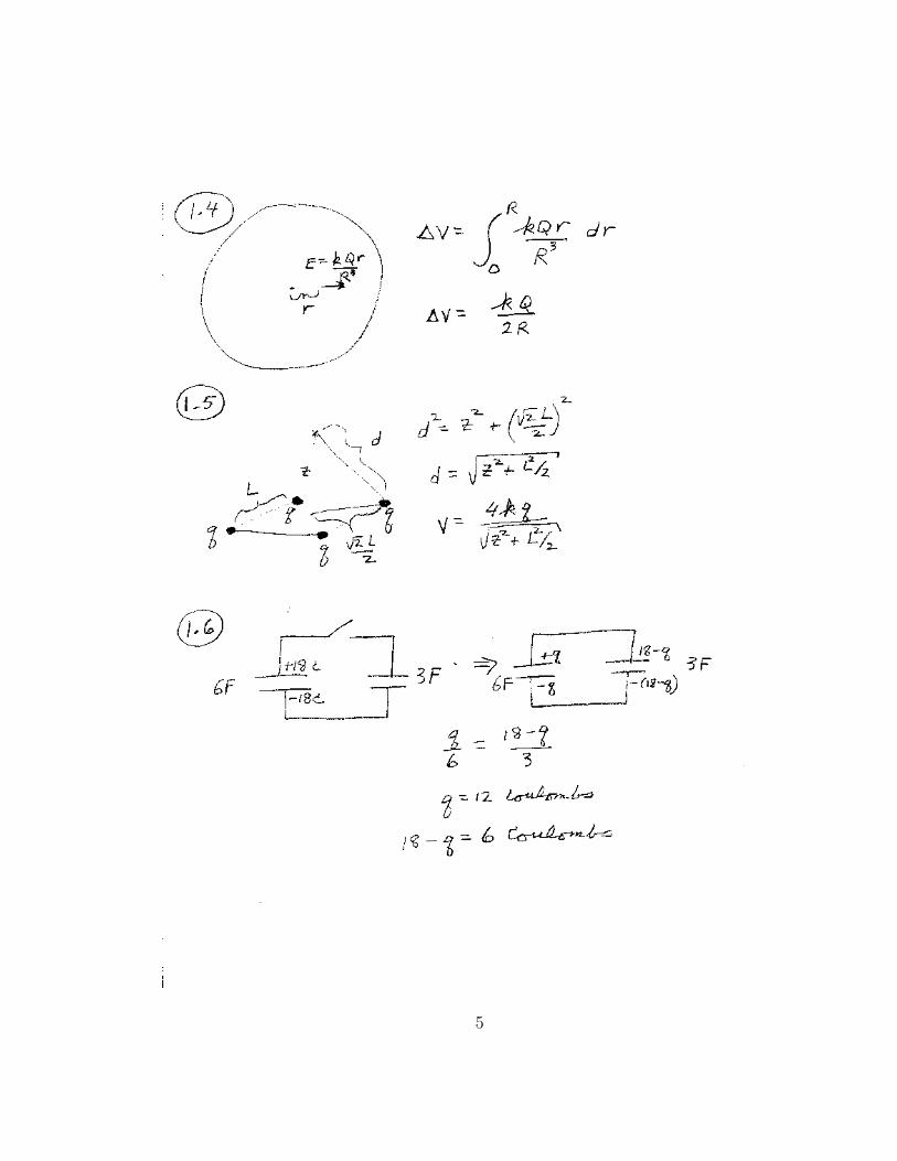
Exercise 1.4Consider a uniformly charged sphere that has a total charge of Q that has a radiusof R. What is the electrostatic potential difference, ∆V , between the center of thesphere and the surface of the sphere?
To find an expression for the potential difference between these two spots, weneed to integrate the electric field from the center to the surface of the sphere: ∆V =∫ ~E · ~dr. Integration is necessary in this case, since the electric field is not constantinside the solid sphere. To start, we first need to find an expression for the electric fieldinside the uniformly charged sphere. Because there is spherical symmetry, Gauss’sLaw will be useful for us.
Since the charge distribution has spherical symmetry, the electric field vectormust point radially away from the center of the sphere, and the magnitudeof the electric field can only depend on r, where r is the distance to the sphere’scenter. Thus, ~E(~r) = E(r)r, where r = |~r|. Because of this spherical symmetry, auseful surface to choose is a spherical shell. On the surface of the shell, the electricfield is perpendicular to the surface and has the same magnitude at any point on thesurface. The surface integral of ~E · ~dA is easy to calculate:
4
5

∫ ∫~E · ~dA =
Qinside
ε0
4πr2E =Qinside
ε0
For points inside the sphere we choose our spherical shell to be inside the sphere, thatis r < R. In this case, the amount of charge inside the shell is just the volume insidethe shell times the charge density: Qinside = (4/3)πr3ρ where ρ is the charge density.Since the charge density of the sphere is ρ = Q/((4/3)πR3), we have
Qinside = Qr3
R3(6)
Substituting into the expression of Gauss’s Law above yields
4πr2E =Qinside
ε0
4πr2E = Qr3
R3ε0
E =Qr
4πε0R3
E = kQr
R3
which is the magnitude of the electric field for points inside the uniformly chargedsphere .
Now we can find the potential difference between the center and a point on thesurface. We just need to integrate ~E · ~dr from the center to the surface of the sphere:
∆V =∫~E · ~dr
=∫ R
0kQ
r
R3dr
=kQ
2R
Exercise 1.5Four small ”point” objects are located at the corners of a square of side L. Each
6
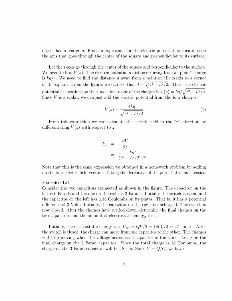
object has a charge q. Find an expression for the electric potential for locations onthe axis that goes through the center of the square and perpendicular to its surface.
Let the z-axis go through the center of the square and perpendicular to the surface.We need to find V (z). The electric potential a distance r away from a ”point” chargeis kq/r. We need to find the distance d away from a point on the z-axis to a corner
of the square. From the figure, we can see that d =√z2 + L2/2. Thus, the electric
potential at locations on the z-axis due to one of the charges is V (z) = kq/√z2 + L2/2.
Since V is a scalar, we can just add the electric potential from the four charges:
V (z) =4kq√
z2 + L2/2(7)
From this expression we can calculate the electric field in the ”z” direction bydifferentiating V (z) with respect to z:
Ez = −∂V∂z
=4kqz
(z2 + L2/2)3/2
Note that this is the same expression we obtained in a homework problem by addingup the four electric field vectors. Taking the derivative of the potential is much easier.
Exercise 1.6Consider the two capacitors connected as shown in the figure. The capacitor on theleft is 6 Farads and the one on the right is 3 Farads. Initially the switch is open, andthe capacitor on the left has ±18 Coulombs on its plates. That is, it has a potentialdifference of 3 Volts. Initially, the capacitor on the right is uncharged. The switch isnow closed. After the charges have settled down, determine the final charges on thetwo capacitors and the amount of electrostatic energy lost.
Initially, the electrostatic energy is is Utot = QV/2 = 18(3)/2 = 27 Joules. Afterthe switch is closed, the charge can move from one capacitor to the other. The chargeswill stop moving when the voltage across each capacitor is the same. Let q be thefinal charge on the 6 Farad capacitor. Since the total charge is 18 Coulombs, thecharge on the 3 Farad capacitor will be 18− q. Since V = Q/C, we have
7
q
6=
18− q3
3q = 6(18)− 6q
q = 12 Coulombs
Thus, the 6 Farad capacitor ends up with ±12 Coulombs on the plates, and the3 Farad capacitor ends up with ±6 Coulombs. The common voltage across eachcapacitor is V = Q/C = 12/6 = 6/3 = 2 Volts.
To find the final energy, we just add the energies of the two capacitors:
Ufinal =Q1V1
2+Q2V2
2
=12(2)
2+
6(2)
2= 18 Joules
Thus, there was a loss of 27− 18 = 9 Joules of electrostatic energy. The 9 Joules ofenergy were transfered into another form, a form that we will learn about later on inthe course.
Exercise 1.7How much electrostatic energy does a uniformly charged solid sphere of radius Rhave? That is, if we were to make a uniformly charged solid sphere, how much energywould it take to bring all the charges from infinity into the ball of charge? Let Q bethe charge of the sphere.
This is a classic problem in electrostatics. The easiest way to solve for the elec-trostatic energy is to use the expression for the electrostatic energy density:
U =ε0E
2
2(8)
We need to know the electric field at all locations in space for a uniformly chargedsphere. We have solved this problem before (Exercise 1.4 above). Let r be the distancefrom the center of the sphere. Then for r < R we found that
| ~E| = kQr
R3(9)
8
and for values of r > R we found in lecture that
| ~E| = kQ
r2(10)
We now need to add up the contribution to the energy over all space. First insidethe sphere:
Ur<R =∫ R
0
ε0E2
2dV
=ε02
∫ R
0
k2Q2r2
R64πr2dr
=kQ2
10R
Note that the volume element dV is equal to 4πr2dr since there is spherical symmetryand the integral is over r. For the space outside of the sphere (R > R), we have
Ur>R =∫ R
0
ε0E2
2dV
=ε02
∫ ∞R
k2Q2
r44πr2dr
=kQ2
2R
Adding the two contributions to the electrostatic energy gives:
Utot = Ur<R + Ur>R
=kQ2
10R+kQ2
2R
=3
5
kQ2
R
This expression represents the energy it would take to bring together a total chargeequal to Q into a sphere. As R→ 0 this energy approaches infinity. One reason thisis an interesting result is that the electron is essentially a ”point” particle. We don’thave an upper limit for the radius of an electron. Experiments show that the electron’sradius is less than 10−19 meters. This small value for R would make the electrostatic
9
10

energy of the electron greater than its rest mass energy. This analysis demonstratesthat Classical physics breaks down at very small length scales.
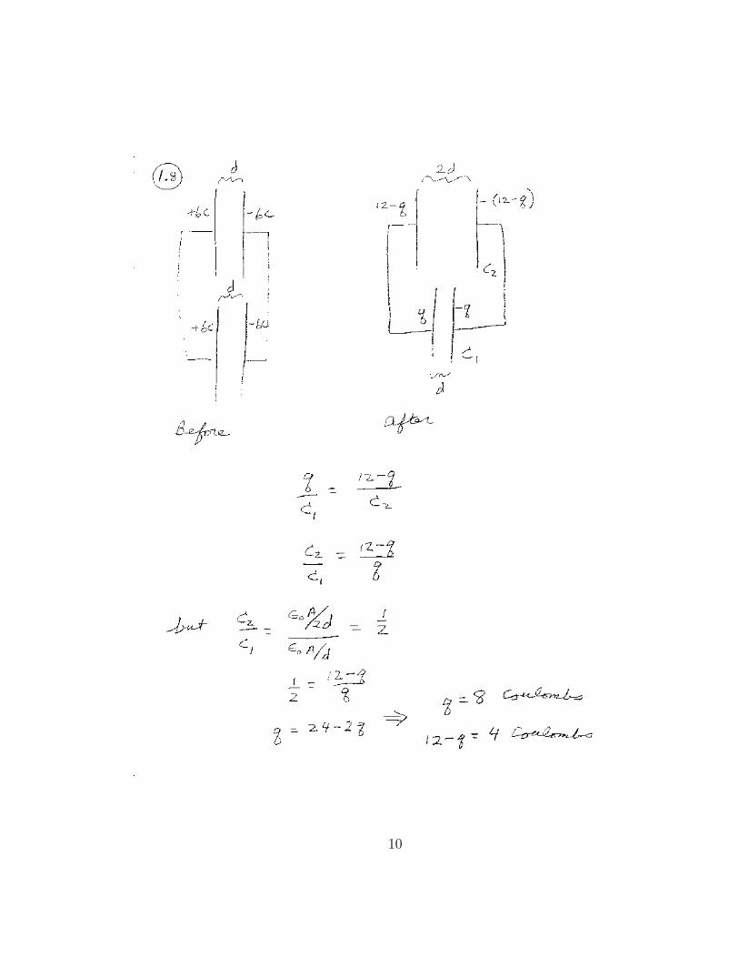
Exercise 1.8Two identical parallel plate capacitors are connected in parallel as shown in the figure.Initially, each one has a charge of ±6 Coulombs on the plates, which are separatedby a distance d. Now, on one of the capacitors the plates are pulled apart until theseparation between them is 2d. What is the final charge distribution on the plates ofthe capacitors?
Here is the key ”physics”: since they are connected in parallel, the voltage acrosseach capacitor is the same. Let q be the final charge on capacitor ”1”, whose plateshave a final separation of d. Then 12 − q is the final charge on the other capacitor”2”, whose plates have a final separation of 2d. This is true, since the sum of thecharge on both capacitors is still 12 Coulombs. Using V = Q/C, we have
q
C1
=12− qC2
C2
C1
=12− qq
Since for a parallel plate capacitor, C = ε0A/d, we have C2/C1 = d/(2d) = 1/2. Thatis, a larger separation between the plates results in a smaller capacitance. In thiscase, the ratio of capacitances is 1/2 since the distance is twice as large in capacitor”2”:
1
2=
12− qq
q = 8 Coulombs
The charge on capacitor ”2” is therefore (12− q) = 4 Coulombs. When the plates ofcapacitor ”2” are separated, 2 Coulombs of charge flows from it to the other capaci-tor. We demonstrated this in lecture. When the plates of the ”slide” capacitor weremoved apart, charge went onto the electroscope and the leaves spread apart more.
Exercise 2.1You have a wire that has a resistance of R0. However, you would like a wire to have
11
a resistance that is twice as large, 2R0. Instead of buying a new wire, you decide tomelt down the original wire and reform it to have a resistance of 2R0 using the sameamount of material. What should the new length be?
We need to know how the resistance of a wire depends on its dimensions: R =ρl/A, where ρ is the resistivity of the material, l is the length and A is the crosssectional area. When we make the new wire, the resistivity does not change since weare using the same material. We need to change l and A in such a way as to doublethe resistance. Since we are using the same amount of material the final volume willequal the original volume:
lA = l0A0 (11)
where l0 and A0 are the length and area of the original wire. The new area A will beequal to A = l0A0/l. Since we want the resistance to be twice as large:
2R0 =ρl
A
2R0 =ρl2
l0A0
For the original wire, R0 = ρl0/A0. With this substitution, we have:
2ρl0A0
=ρl2
l0A0
2l0 =l2
l0
l =√
2 l0
So the new wire should have a length that is√
2 greater than the original wire, andan area that is
√2 smaller than the original wire. This way, the volume is the same,
but the resistance is doubled.
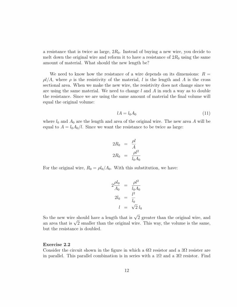
Exercise 2.2Consider the circuit shown in the figure in which a 6Ω resistor and a 3Ω resister arein parallel. This parallel combination is in series with a 1Ω and a 3Ω resistor. Find
12
13

the current through and the voltage across each resistor.
This combination of resistors can be broken up into parallel and series sections.This is nice, because one can calculate the equivalent resistance of the whole circuitand find the current delivered by the battery. Once this is done, one can go piece bypiece to determine the currents and voltages across the resistors. First we determinethe resistance of the whole circuit.
The 6Ω and 3Ω resistors in parallel are equivalent to
1
R36
=1
3+
1
6R36 = 2Ω
2 Ohms. This 2Ω parallel combination is in series with the other two resistors, so thetotal resistance of the circuit, RT , is
RT = 1 + 2 + 3 = 6Ω (12)
The current that is supplied by the battery is I = V/RT , or
Ibattery =12
6= 2 amps (13)
Thus, 2 amps flows through the 1Ω resistor and the 3Ω resistor that is in series.Now the voltages across all the resistors can be determined. Across the 1Ω resis-tor, V = IR = 2(1) = 2 Volts. Across the 3Ω resistor in series with the battery,V = IR = 2(3) = 6 Volts. The voltage across the 3Ω and 6Ω resistors in parallelare V = 12 − 2 − 6 = 4 volts. The current through the 6Ω resistor is thereforeI = V/R = 4/6 = 2/3 Amps. The current through the 3Ω resistor (in the parallelcombination) is I = V/R = 4/3 Amps.
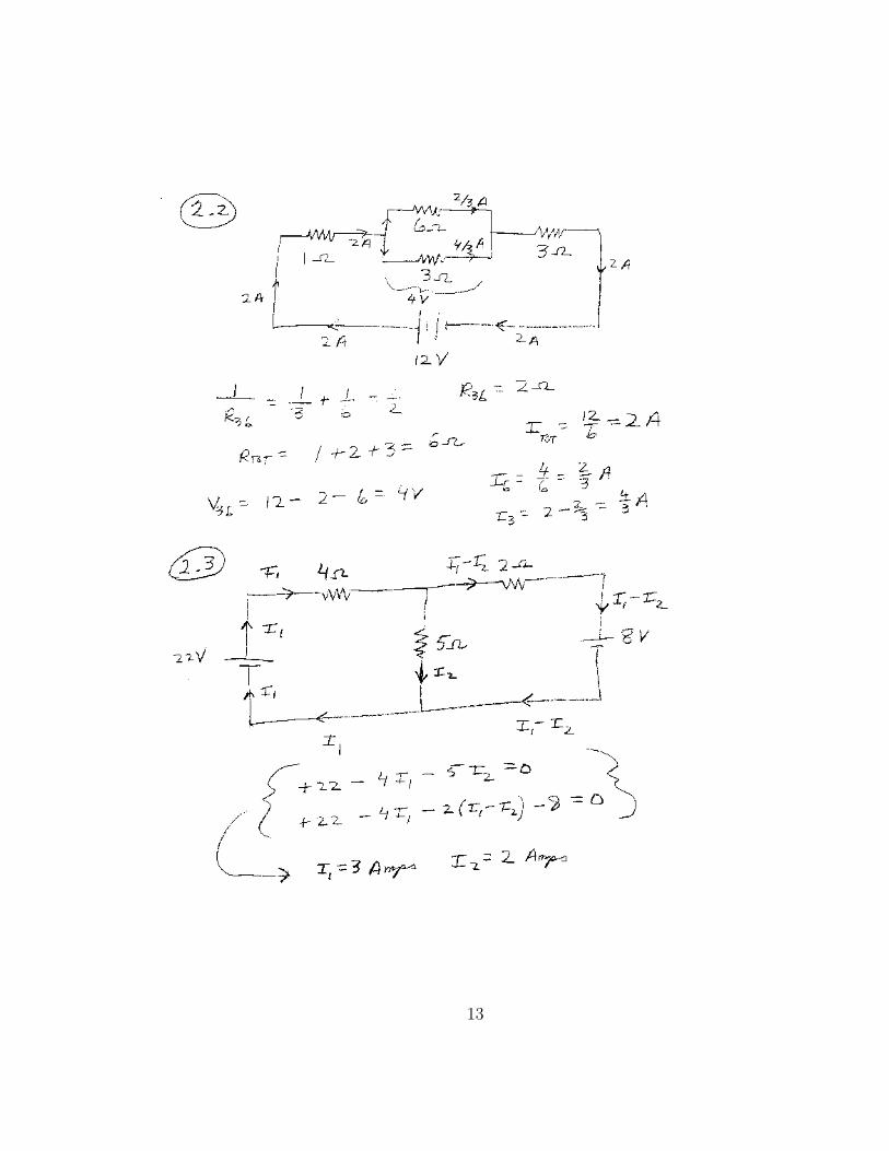
Exercise 2.3Consider the combination of resistors and batteries shown in the figure. Find thecurrent through and the voltage across each resistor.
In this case it is not possible to combine the resistors into equivalent series andparallel pieces. We cannot determine a total resistance for the circuit as we did inthe last example. We need to use the basic physics equations: Kirchoff’s Laws. We
14
start by assigning a value for the current in the various wires. Let I1 be the currentthat flows our of the 22 volt battery, and also through the 4Ω resistor. Let I2 bethe current through the 5Ω resistor. Since the charge flow into a junction equals thecharge flow out, the current through the 2Ω resistor will be (I1− I2). This is also thecurrent that flows into the ”+” side of the 8 volt battery. Using this labeling of thecurrent we have satisfied Kirchoff’s current law.
Now we need to express Kirchoff’s voltage law mathematically. If the currentsare not changing in time (and there are no changing magnetic fields) The voltagechanges around a closed loop equals zero. Starting in the lower left corner and goingclockwise around the left loop yields:
22− 4I1 − 5I2 = 0
22 = 4I1 + 5I2
Starting in the lower left corner and going clockwise around the outer loop yields:
22− 4I1 − 2(I1 − I2)− 8 = 0
14 = 6I1 − 2I2
Now we need to solve the two equations for the two unknowns, I1 and I2. Multiplyingthe top one by 6 and the bottom one by 4 and subtracting allows us to solve for I2:I2 = 2 Amps. Substituting I2 = 2 into one of the equations results in I1 = 3 Amps.
Thus, 3 amps flows out of (and back into) the 22 volt battery as well as throughthe 4Ω resistor. A current of 2 amps flows through the 5Ω resistor. A current of(3 − 2) = 1 amp flows through the 2Ω resistor. A current of 1 amp flows into thepositive terminal of the 8 volt battery. That is, the 8 volt battery gets ”charged-up”.Note that we would have obtained the same results if we would have chosen diffentvariables for the currents and used different paths for the voltage changes.
Exercise 2.4Your flashlight contains a D-cell battery connected to a .75Ω light. The D-cell batteryis 1.5 volts and has a capacity rating of 10 Amp-Hours. Find: the current flow in thecircuit, the power dissipated by the light, the total energy that the battery originallyhad, and the length of time that the battery can continuously light the light beforeit is ”dead”.
a) The current is found using I = V/R:
15

I =V
R=
1.5
.75= 2 amps (14)
b) The power dissipated by the light bulb is P = I2R:
P = I2R = (2)2(.75) = 3 Watts (15)
or 3 Joules/sec.
c) The total energy originally available from the battery can be found by first calcu-lating the available charge: 10 Amp-hours = (10 C/sec)(3600 sec) = 36000 Coulombs.Since this amount of charge flows through a potential voltage differenct of 1.5 volts,we have
Energy = (36000 Coulombs)(1.5 V olts) = 54000 Joules (16)
d) Since the battery uses up energy at a rate of 3 Watts = 3 Joules/sec, it can lastfor a time of 54000/3 = 18000 seconds or 5 hours.
Exercise 2.5You want to watch a TV show for four hours, but your parents think this will runthe electric bill too high and cost too much money. Your TV has a power rating of200 Watts. How much will it cost to watch the 4 hour show if electric energy costs14 cents per KwHr?
To find the total cost of watching the TV show, we will first determine the amountof energy used in units of Kw-Hrs. Energy = (.200 Kw)(4 hours) = 0.8 KwHr. Thismuch energy will cost (14 cents/KwHr)(0.8 KwHr) = 11.2 cents. Once you showyour parents how little it costs, they will probably let you watch the show.
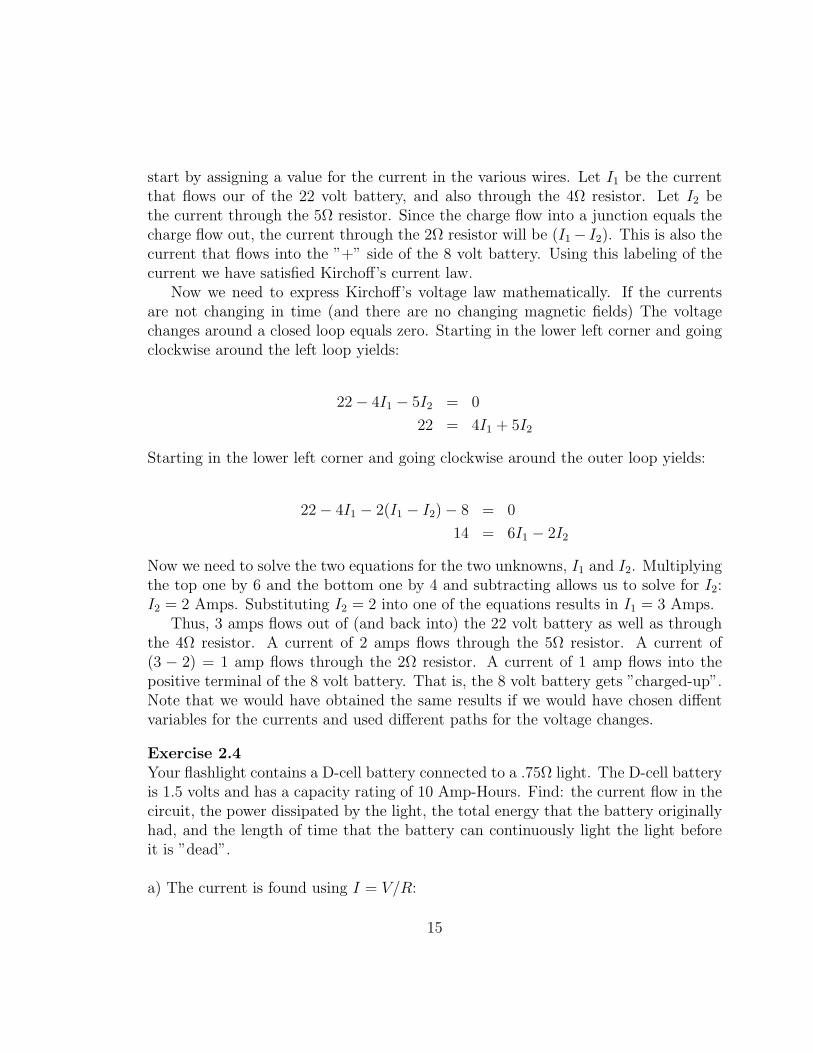
Exercise 2.6You go to your friend’s house for dinner and he is cooking hot dogs using an electricalcircuit. The circuit is shown in the figure, and consist of 3 hot dogs. Two of the hotdogs, which are Angel Dogs, are connected in parallel, and this parallel combinationis connected in series with one hot dog, which is a Dodger Dog. Your friend connectsa voltage of 120 volts across the hot dog circuit. How much current flows througheach hot dog, how much power is delivered to each hot dog, and what is the potentialdifference between the points a and b as shown in the figure. Point a is in the middle
16
17
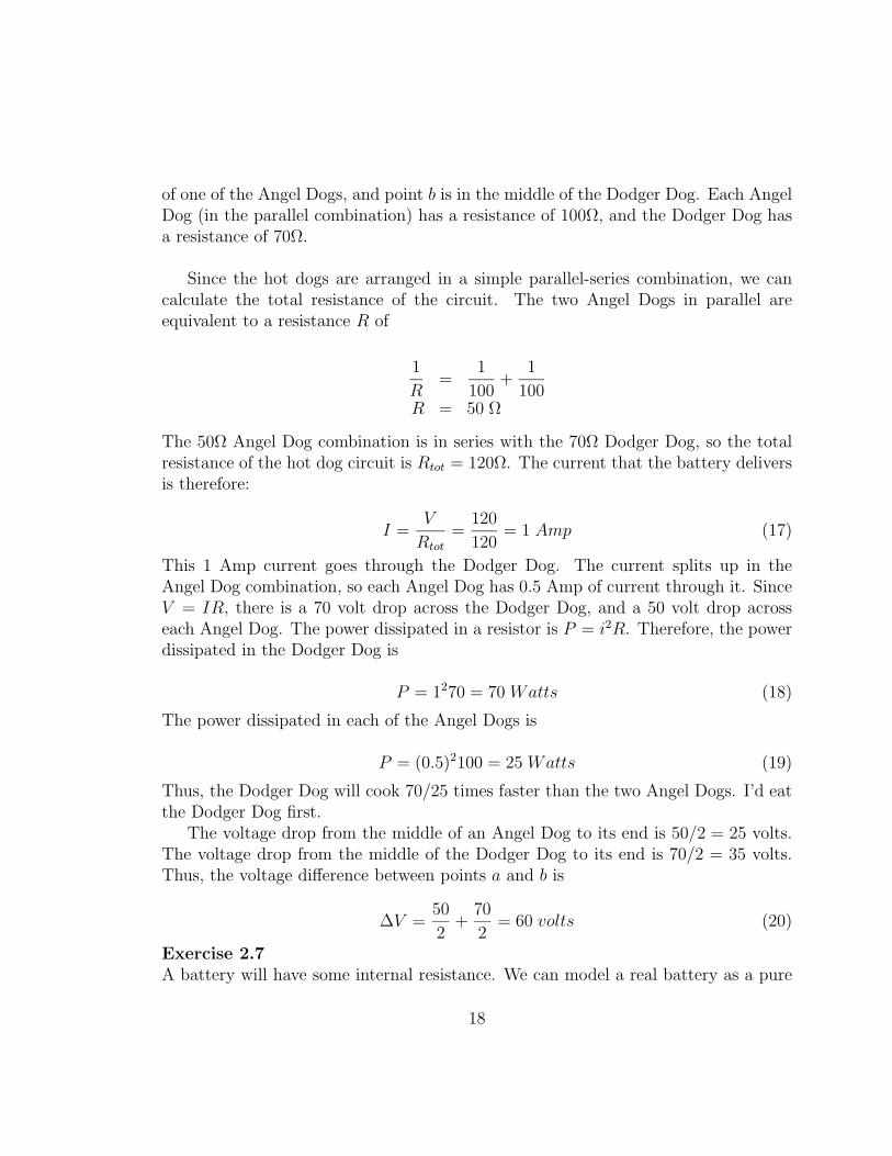
of one of the Angel Dogs, and point b is in the middle of the Dodger Dog. Each AngelDog (in the parallel combination) has a resistance of 100Ω, and the Dodger Dog hasa resistance of 70Ω.
Since the hot dogs are arranged in a simple parallel-series combination, we cancalculate the total resistance of the circuit. The two Angel Dogs in parallel areequivalent to a resistance R of
1
R=
1
100+
1
100R = 50 Ω
The 50Ω Angel Dog combination is in series with the 70Ω Dodger Dog, so the totalresistance of the hot dog circuit is Rtot = 120Ω. The current that the battery deliversis therefore:
I =V
Rtot
=120
120= 1 Amp (17)
This 1 Amp current goes through the Dodger Dog. The current splits up in theAngel Dog combination, so each Angel Dog has 0.5 Amp of current through it. SinceV = IR, there is a 70 volt drop across the Dodger Dog, and a 50 volt drop acrosseach Angel Dog. The power dissipated in a resistor is P = i2R. Therefore, the powerdissipated in the Dodger Dog is
P = 1270 = 70 Watts (18)
The power dissipated in each of the Angel Dogs is
P = (0.5)2100 = 25 Watts (19)
Thus, the Dodger Dog will cook 70/25 times faster than the two Angel Dogs. I’d eatthe Dodger Dog first.
The voltage drop from the middle of an Angel Dog to its end is 50/2 = 25 volts.The voltage drop from the middle of the Dodger Dog to its end is 70/2 = 35 volts.Thus, the voltage difference between points a and b is
∆V =50
2+
70
2= 60 volts (20)
Exercise 2.7A battery will have some internal resistance. We can model a real battery as a pure
18

voltage source of voltage V0 with a small resistor of resistance r in series with it. Todetermine V0 and r you place a a resistor across the battery and measure its voltage.Here is the data you get: For a 10Ω resistor across the battery, the voltage is 1.27volts, and for a 20Ω resistor across the battery, the voltage is 1.38 volts. What is V0
and r for the battery?
The circuit is shown in the figure. When a 10Ω resistor is placed across the battery,it is in series with r. The current is therefore: I = V0/(10 + r). The voltage dropacross the real battery is 1.27 = V0 − Ir. Substituting in for I gives
1.27 = V0 −V0r
10 + r
1.27 =10V0
10 + r12.7 + 1.27r = 10V0
A similar analysis can be when the 20Ω is connected. The current that flows isI = V0/(20 + r). The voltage drop across the real battery now is 1.38 = V0 − Ir.Substituting in for I gives
1.38 = V0 −V0r
20 + r
1.38 =20V0
20 + r27.6 + 1.38r = 20V0
We have two equations with two unknowns: V0 and r. Solving for V0 and r givesr ≈ 1.9Ω and V0 ≈ 1.51 Volts.
Exercise 2.8Your car battery has gone dead and you want to replace it with a large capacitor.Your old car battery is 12 volts and has a capacity of 40 amp-hours. What shouldthe capacitance of the capacitor be so that a 12 volt difference across the plates willresult in the same energy as the battery.
To solve the problem, we can first calculate the energy contained in the car battery.40 amp-hours is equal to a charge of 40 Coulombs/sec (3600 sec) = 144000 Coulombs.
19

The energy that a new battery has is U = 12 V olts(144000 C) = 1.728× 10⁶ Joules.Equating this energy with the energy contained in a capacitor yields
U =CV 2
2
1.728× 106 =C 122
2C = 24000 Farads
This is a huge capacitance, and is impractical as a substitute for the battery. Wecould put a higher voltage on the capacitor, say 100 volts. Then the capacitancewould be
U =CV 2
2
1.728× 106 =C 1002
2C = 245.6 Farads
This is still quite large. Until someone comes up with such a large capacitor, we hadbetter just buy a new battery.
Exercise 2.9Someone has connected 5 resistors as shown in the figure. This kind of connection iscalled a Wheatstone Bridge. If 6 Amps enters from the left, 2 Amps flow through the5Ω resistor and 3 Amps flows through resistor R2. Find the value of R1, R2, and thetotal resistance of the Wheatstone Bridge.
Since 2 Amps flows through the 5Ω resistor, there must be 6−2 = 4 Amps flowingthrough the 2Ω resistor. Also, since there is 3 Amps flowing through resistor R2 and6 Amps leaves the circuit, the current that flows through the 1Ω resistor must be6− 3 = 3 Amps. Therefore, 1 Amp must flow through R1 from a to b.The voltage at c, Vc, minus the voltage at a, Va, is Vc−Va = 4(2) = 8 Volts. SimilarlyVc−Vb = 5(2) = 10 Volts. Therefore, the voltage drop across R1 is Va−Vb = 10−8 = 2Volts. So the value of R1 is R1 = 2/1 = 2Ω, since there is one amp flowing throughR1. The voltage difference between c and d is the same if one goes via the bottompath or the top path. So,
20

21
4(2) + 3(1) = 2(5) + 3R2
11 = 10 + 3R2
R2 =1
3Ω
The voltage difference across the whole circuit is Vc − Vd = 4(2) + 3(1) = 11 Volts.Since 6 Amps flows through the circuit, the total Resistance is 11/6 ≈ 1.83Ω.Note: It is not possible to break up this circuit into a combination of series andparallel pieces. One has to use Kirchhoff’s Laws to solve for the currents and voltagedifferences in this Wheatstone Bridge set-up.
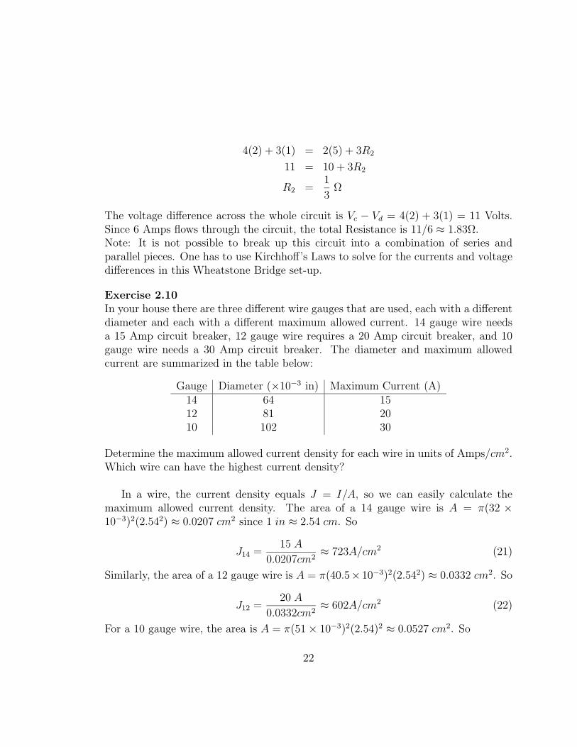
Exercise 2.10In your house there are three different wire gauges that are used, each with a differentdiameter and each with a different maximum allowed current. 14 gauge wire needsa 15 Amp circuit breaker, 12 gauge wire requires a 20 Amp circuit breaker, and 10gauge wire needs a 30 Amp circuit breaker. The diameter and maximum allowedcurrent are summarized in the table below:
Gauge Diameter (×10−3 in) Maximum Current (A)14 64 1512 81 2010 102 30
Determine the maximum allowed current density for each wire in units of Amps/cm2.Which wire can have the highest current density?
In a wire, the current density equals J = I/A, so we can easily calculate themaximum allowed current density. The area of a 14 gauge wire is A = π(32 ×10−3)2(2.542) ≈ 0.0207 cm2 since 1 in ≈ 2.54 cm. So
J14 =15 A
0.0207cm2≈ 723A/cm2 (21)
Similarly, the area of a 12 gauge wire is A = π(40.5× 10⁻³)2(2.542) ≈ 0.0332 cm2. So
J12 =20 A
0.0332cm2≈ 602A/cm2 (22)
For a 10 gauge wire, the area is A = π(51× 10−3)2(2.54)2 ≈ 0.0527 cm2. So
22
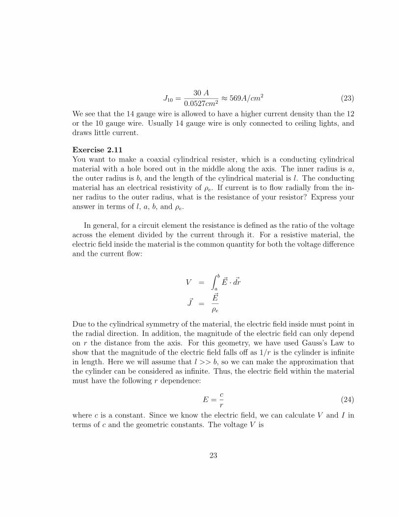
J10 =30 A
0.0527cm2≈ 569A/cm2 (23)
We see that the 14 gauge wire is allowed to have a higher current density than the 12or the 10 gauge wire. Usually 14 gauge wire is only connected to ceiling lights, anddraws little current.
Exercise 2.11You want to make a coaxial cylindrical resister, which is a conducting cylindricalmaterial with a hole bored out in the middle along the axis. The inner radius is a,the outer radius is b, and the length of the cylindrical material is l. The conductingmaterial has an electrical resistivity of ρe. If current is to flow radially from the in-ner radius to the outer radius, what is the resistance of your resistor? Express youranswer in terms of l, a, b, and ρe.
In general, for a circuit element the resistance is defined as the ratio of the voltageacross the element divided by the current through it. For a resistive material, theelectric field inside the material is the common quantity for both the voltage differenceand the current flow:
V =∫ b
a
~E · ~dr
~J =~E
ρe
Due to the cylindrical symmetry of the material, the electric field inside must point inthe radial direction. In addition, the magnitude of the electric field can only dependon r the distance from the axis. For this geometry, we have used Gauss’s Law toshow that the magnitude of the electric field falls off as 1/r is the cylinder is infinitein length. Here we will assume that l >> b, so we can make the approximation thatthe cylinder can be considered as infinite. Thus, the electric field within the materialmust have the following r dependence:
E =c
r(24)
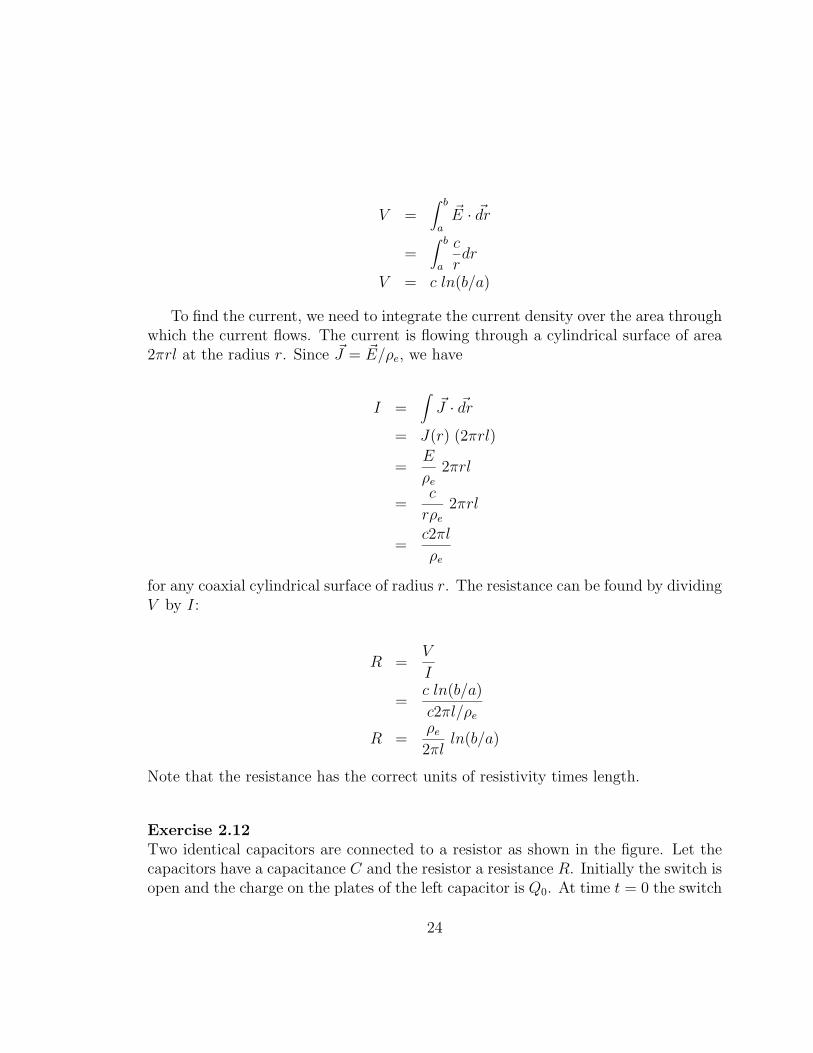
where c is a constant. Since we know the electric field, we can calculate V and I interms of c and the geometric constants. The voltage V is
23
V =∫ b
a
~E · ~dr
=∫ b
a
c
rdr
V = c ln(b/a)
To find the current, we need to integrate the current density over the area throughwhich the current flows. The current is flowing through a cylindrical surface of area2πrl at the radius r. Since ~J = ~E/ρe, we have
I =∫~J · ~dr
= J(r) (2πrl)
=E
ρe2πrl
=c
rρe2πrl
=c2πl
ρe
for any coaxial cylindrical surface of radius r. The resistance can be found by dividingV by I:
R =V
I
=c ln(b/a)
c2πl/ρe
R =ρe2πl
ln(b/a)
Note that the resistance has the correct units of resistivity times length.
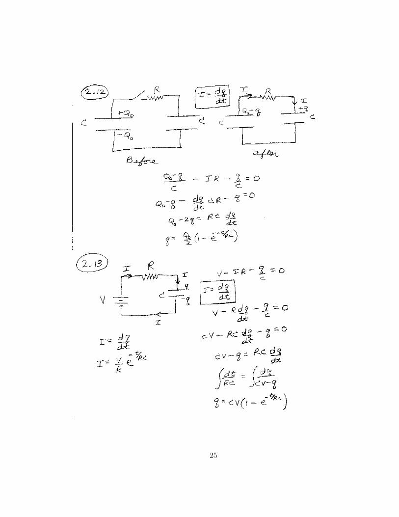
Exercise 2.12Two identical capacitors are connected to a resistor as shown in the figure. Let thecapacitors have a capacitance C and the resistor a resistance R. Initially the switch isopen and the charge on the plates of the left capacitor is Q0. At time t = 0 the switch
24
25

is closed. Find an expression for the charge on the right capacitor as a function of time.
Let q(t) be the charge on the plates of the capacitor on the right at time t. Thenthe charge on the plates of the capacitor on the left is Q0−q(t), since the total chargemust add up to Q0. Let the current at any time be I(t). Then, adding up the voltagechanges around the loop gives:
Q0 − qC
− IR− q
C= 0 (25)
Here we have used the properties that the voltage change across a capacitor is Q/Cand across a resistor as IR. Note that the zero on the right is only true in thecase of steady state currents. Here the current is changing, but the change is slowenough that the sum of the voltage drops around a closed loop is essentially zero.We will learn in the next section the reason that this approximation is good: the selfinductance of the circuit is very small.
We now need to relate I to q. As seen in the figure, I = +dq/dt. We have a +sign here since we have chosen the direction of I to go into the + side of the rightcapacitor. Substituting into the above equation gives:
Q0 − qC
− dq
dtR− q
C= 0
RCdq
dt= Q0 − 2q
We can solve the differential equation above by integration:
dt
RC=
dq
Q0 − 2q∫ dt
RC=
∫ dq
Q0 − 2qt
RC= −1
2ln(Q0 − 2q)|q0
− 2t
RC= ln(Q0 − 2q)− ln(Q0)
e−2t/(RC) =Q0 − 2q
Q0
q =Q0
2(1− e−2t/(RC))
26

Initially, at t = 0, q = 0. As t→∞, then q → Q0/2. Note also that the capacitancein the RC time constant is C/2. Thus, in this circuit, it is as if the two capacitorsare connected in series.
Exercise 2.13Consider a resistor and capacitor connected in series to a battery as shown in thefigure. Let the resistor have resistance R, the capacitor a capacitance C and thebattery a voltage of V . Initially the switch is open and the capacitor is uncharged.When the switch is closed, current flows, and the capacitor charges up until it isreaches a final charge of Q = CV . After the capacitor has charged up, show that theenergy supplied by the battery equals the energy dissipated by the resistor plus thefinal energy stored in the capacitor.
We label the charge on the plates of the capacitor as q and the current as I flowingfrom the positive side of the battery. Summing up the voltage changes around theloop:
V −RI − q
c= 0 (26)
Using the direction we have defined for I, we have I = dq/dt. Substituting into theabove equation yields:
Rdq
dt= V − q
C(27)
We can solve this differential equation as we did with the last problem. After multi-plying by C and arranging terms we have:
∫ dt
RC=
∫ dq
CV − qt
RC= −ln(CV − q)|q0
− t
RC= ln(
CV − qCV
)
q = CV (1− e−t/(RC))
Note that the charge on the capacitor at t = 0 is zero, and as t → ∞ the chargeapproaches q(final)→ CV . The current in the circuit is
27

I =dq
dt
I =V
Re−t/(RC)
Now we can calculated the energy transfer in the different elements in charging upthe capacitor. The power supplied by the battery is P = V I. The energy supplied bythe battery is found by integrating the power from t = 0 to t =∞, Ubattery =
∫Pdt:
Ubattery =∫ ∞
0V I dt
=∫ ∞
0
V 2
Re−t/(RC) dt
= V 2C
The power dissipated by the resistor is P = IR = I2R. Integrating the powerfrom t = 0 to t =∞ gives
Uresistor =∫ ∞
0I2R dt
=∫ ∞
0
V 2
Re−2t/(RC) dt
=V 2C
2
Thus, the energy that was delivered to the capacitor is Ucapacitor = V 2C − V 2C/2 =V 2C/2, which is correct expression for the energy stored in a capacitor. All the energyis accounted for.
28