exchange of engineering data for communication … step towards lossless data exchange within...
TRANSCRIPT

2015 ODVA Industry Conference 1 ©2015 ODVA, Inc.
Exchange of engineering data for communication systems based on AutomationML using an EtherNet/IPTM example
Development of a vendor-neutral data exchange format for the application in existing tool chains
Concept development for the realization of various relevant structural, behavioral and device configuration data and the
possibility of horizontal data integration
Dipl.-Wirtsch.-Ing. Falko Bendik; apl. Prof. Dr.-Ing. habil. Arndt Lüder;
Dipl.-Ing. Nicole Schmidt;
Research Assistant; Head of CVS, Research Assistant;
Research Assistant;
Otto-von-Guericke-University Magdeburg Faculty of Mechanical Engineering
Institute of Ergonomics, Manufacturing Systems and Automation (IAF) / Chair for Factory Operation and Manufacturing Systems
Presented at the ODVA
2015 Industry Conference & 17th Annual Meeting October 13-15, 2015 Frisco, Texas, USA
Executive Summary Communication systems are an important part of modern control systems used within industrial
production systems. They enable the interaction of control systems with the used equipment to satisfy the
different requirements related to the controlled behavior of the production system.
During the engineering process of production systems and its embedded control systems
communications systems need to be considered in detail. At early stages of the engineering process
relevant data for the communication system design is created and the results of the communication
system engineering are needed in later phases. However, this data exchange is still a technical challenge
as there is no suitable data exchange format available which enables a consistent and lossless transfer of
information between engineering tools covering all relevant communication system engineering
information.
2015 ODVA Industry Conference 2 ©2015 ODVA, Inc.
To solve this problem, a methodology for modeling the communications systems was developed by the
AutomationML association using the basis of the data exchange format AutomationML, which will be
presented in this paper. Finally, this methodology is applied on an EtherNet/IPTM example.
Motivation The requirements on the engineering of production systems respectively automation systems have been
growing continuously in the last years. This effects the duration of the engineering project, the complexity
of the systems to be created, as well as the amount of data to be treated [1, 2]. To cope with these
challenges engineers have developed highly sophisticated engineering tools assisting the engineers with
their work. Thus, within the different applicable engineering process different sets if software tools are
involved exploiting different engineering artifacts [3, 7]. To make the engineering processes efficient and
fault free the created engineering artifacts or parts of them have to be exchanged between the
engineering tools within the established engineering tool networks.
Today, an important part of the automation of production systems is the industrial communication system.
That connects the various automation components and, thus, makes modular control structures and
distributed control systems possible. As for all engineering artifacts, for the engineering of those
communication systems it is necessary to enable a consistent exchange of engineering data [4].
Here, different use cases of data exchange may be relevant. A first intuitive example is the transfer of
configuration information for communication modules of automation devices, which describes device
addressing and communication package structuring. Thus, information must be transmitted from PLC
programming tools to the corresponding configuration tools to automation devices.
Another example is the transfer of device configuration data and data structures describing the
communication network from PLC programming tools or configuration tools of automation devices to
documentation tools for representing the overall structure of a communication system for maintenance or
diagnostics purposes (see Figure 1).

2015 ODVA Industry Conference 3 ©2015 ODVA, Inc.
Figure 1: Considered application cases
So far, various user organizations and companies have developed and supported different description
formats (like FDCML [8], EDDL [6]) FDT-DTM [14], which primarily focus on the exchange of device
configuration data [5]. This is, however, not sufficient regarding the applications mentioned above, as they
describe only data of a device and, for example, do not contain topological information or information on
communication links and their quality.
For this reason, the AutomationML association has developed a method based on AutomationML [9] to
represent engineering data for communication systems. This method reflects the distinction between a
logical and a physical topology of a communication system as illustrated in Figure 2.
Electrical Planning
Mechanical Engineering
Bus Configuration
PLC Programming
Test / Virtual Commissioning
Commissioning /Device
Configuration
Monitoring, Maintenance
Plant Planning
Documentation
Robot Programming
Simulation
*.aml

2015 ODVA Industry Conference 4 ©2015 ODVA, Inc.
Figure 2: Logical and physical topology of communication systems
A logical topology comprises control applications and their components exchanging information on a
logical level. Here, the addressing of applications and the expected transmission rate of information
between application parts might be of interest for modeling. A physical topology maps the communication
devices and the built up physical communication links between them. Again, addresses and transmission
rates are relevant, but on a different abstraction level representing the system capabilities. Both
topologies are interlinked; the physical topology must implement the logic one.
AutomationML has developed and documented basic semantic libraries and process models in the
AutomationML Whitepaper Part 5 – “Communication” to enable the representation of different
communication technologies and different communication protocols. This paper will sketch the
developments accomplished so far by means of an EtherNet/IPTM example.
To make the above named problem of information exchange more intensive, companies, (especially
system integrators of different industries) have to face the challenge of increasing technological
divergence. Especially Small and Medium-sized Enterprises (SMEs) are intended to be enabled to meet
high individualization of kind and characteristics of communication technologies within the use cases of
their customers. They require support for protocol- and architecture independent design, configuration
and documentation of arbitrary industrial communications networks. They need appropriate procedures
and data models for these processes.
Here, the AutomationML based communication system modeling can provide a first assistance to face
this challenge. This paper will show preliminary results of an ongoing research project at the Otto-von-
Physical Device
Logical Device
LogicalEndPoint
PhysicalEndPoint
VariableInterface
Physical Device
Logical Device
LogicalEndPoint
PhysicalEndPoint
VariableInterface
Communication
Package
PhysicalConnection
Inte
rna
lLin
k
Inte
rna
lLin
kIn
tern
alL
ink
Inte
rna
lLin
k
LogicalConnection
Communication
Package
DataObjectInte
rna
lLin
k
Inte
rna
lLin
k
Inte
rna
lLin
k
Inte
rna
lLin
k

2015 ODVA Industry Conference 5 ©2015 ODVA, Inc.
Guericke-University Magdeburg related to modeling and planning of communication systems including
protocol details using AutomationML as modeling language. This project focuses on the application field
of factory automation and energy generation and distribution systems and strives to reduce the duration
of installation and commissioning of the communications systems by 20%, to limit the error rate, and to
improve communication system documentation. The project focuses on the development and use of
communications system models within a neutral format, which are qualified for project parts and, beyond
that, for the universal use within arbitrary applications. The project focuses on the application field of
photovoltaic. Specifically, this paper will show the application of an Ethernet-Network and EtherNet/IPTM
as an example.
What is needed - a requirement analysis First step towards lossless data exchange within engineering of communication systems is to identify the
types of information characterizing a communication system. Communication systems are necessary for a
variety of applications in practice. Some of the most relevant applications will be described below. With
these it is shown, which information should be covered by a method for a neutral exchange of
communication system engineering information.
Starting point of the investigations is the engineering process of a production system [10, 11, 12]. In this
process mainly, the mechanical and electrical engineering, control programming, virtual commissioning,
and commissioning are executed. The first two activities are executed partly in parallel resulting in a
definition of involved automation devices and their wiring. In the subsequent the control programming, the
runtime information (represented by control variables) to be exchanged between automation devices by
use of communication systems are defined. This information (variables) must be transmitted through a
communication system. In addition technical details such as data types, transmission rates, etc. are
specified.
This information is used in the electrical engineering, for example, for specifying wiring diagrams, cable
lines and to specify device configurations. This is used to setup the physical realization of the intended
data exchange. The device configurations, variable lists, and link descriptions which are created in the
control programming as well as in the mechanical and electrical construction are needed afterwards to
create the appropriate system models in the virtual commissioning.
During the commissioning the device configuration data is required, for executing the device configuration
and the variable declaration and linking description for monitoring and diagnosis.
The mentioned application describes only a small part of the relevant applications. However, it could be
seen, which information are needed to describe the modeling method:
Control applications usually consist of a set of application components. These components are
linked with each other by exchanging variable. Therefore, they need to establish logical
connections by logical interfaces (namely the corresponding exchanged variables). It is important
to identify the requirements in terms of communication properties on the exchange of data within

2015 ODVA Industry Conference 6 ©2015 ODVA, Inc.
the logical connections. Similarly, properties of the control application components could be
interesting such as processing times, characteristics of logical interfaces or a port number.
The individual control application components are running on different physical devices. Between
these physical devices the logical connections must be realized by the physical data exchange.
Accordingly, a physical device has interfaces for physical connections (necessary cables for
communication system realization). Additionally, it must be possible to describe the active and
passive infrastructure components such as switches, interface converters, plug, or cable types
based on the selected communication technology. In analogy to the control application parts, the
logical connections, and the logical interfaces, it must be possible to represent the properties of
the physical devices, the physical interfaces and the physical links.
In order to represent the relations between logical and physical connections, it is necessary to
map the corresponding structures at least at the used interfaces to each other.
Within the communication system information is transmitted via data packages. They represent
the mapping of variables within the data package sender to variables within the data package
receiver. Thus they shall be assigned to logical connections. Nevertheless, they are
implementation technology dependent as their header represents the physical implementation of
the communication system.
The resulting structure is shown in Figure 3.

2015 ODVA Industry Conference 7 ©2015 ODVA, Inc.
Figure 3: Example of the objects to be imaged
Brief overview of AutomationML AutomationML (AML) [10] is a neutral, free, open, XML based, and standardized data exchange format,
which allows a lossless data exchange within the engineering process of production systems. For that
purpose, it was not developed as a completely new format but consists of three pre-existing formats,
which were extended, adapted, and combined appropriately. By doing so, it is possible to model
production system data starting at the plant structure, over geometry and kinematics information up to
sequences and logical dependencies (see Figure 4).
PLC IO Device
Physicaldevice
Active infra-structure device
Main controlapplication
IO function
Physicalend pointof device
Logical device
Logical end pointof device
Physicalconnection
with end point
Logical connection
with end points
Mapping oflogical tophysical
interfaces
Wire 1
Wire 2
Logical Connection A
AutomationML Communication
Variable / Signal
interface
Mapping ofVariable /
Signal
interface todatagram
object
Datagramobject
PDU
PDU 1
2015 ODVA Industry Conference 8 ©2015 ODVA, Inc.
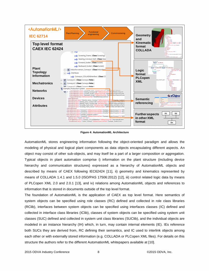
Figure 4: AutomationML Architecture
AutomationML stores engineering information following the object-oriented paradigm and allows the
modeling of physical and logical plant components as data objects encapsulating different aspects. An
object may consist of other sub-objects, and may itself be a part of a larger composition or aggregation.
Typical objects in plant automation comprise i) information on the plant structure (including device
hierarchy and communication structures) expressed as a hierarchy of AutomationML objects and
described by means of CAEX following IEC62424 [11], ii) geometry and kinematics represented by
means of COLLADA 1.4.1 and 1.5.0 (ISO/PAS 17506:2012) [12], iii) control related logic data by means
of PLCopen XML 2.0 and 2.0.1 [13], and iv) relations among AutomationML objects and references to
information that is stored in documents outside of the top level format.
The foundation of AutomationML is the application of CAEX as top level format. Here semantics of
system objects can be specified using role classes (RC) defined and collected in role class libraries
(RClib), interfaces between system objects can be specified using interfaces classes (IC) defined and
collected in interface class libraries (IClib), classes of system objects can be specified using system unit
classes (SUC) defined and collected in system unit class libraries (SUClib), and the individual objects are
modeled in an instance hierarchy (IH) which, in turn, may contain internal elements (IE). IEs reference
both SUCs they are derived from, RC defining their semantics, and IC used to interlink objects among
each other or with externally stored information (e.g. COLLADA or PLCopen XML files). For details on this
structure the authors refer to the different AutomationML whitepapers available at [10].
1
Top level format
CAEX IEC 62424
Plant Topology Information
Mechatronics
Networks
Devices
Attributes
Geometry
andKinematic format
COLLADA
Logic
formatPLCopenXML
Semantic
referencing
Further aspects
in other XMLformat
D1 D2
Dn
IEC 62714Plant Planning
Functional engineering
Commissioning
2015 ODVA Industry Conference 9 ©2015 ODVA, Inc.
AutomationML is standardized within the International Electrotechnical Commission (IEC), where at IEC
62714-1 “Part 1: Architecture and General Requirements” and IEC 62714-2 “Part 2: Role class libraries”
are international standards (IS) already. The entire standard series is specified and maintained in
cooperation with the expert group “Engineering” of the Deutsche Kommission Elektrotechnik Elektronik
Informationstechnik (DKE) and the working group 9 of International Electrotechnical Commission (IEC)
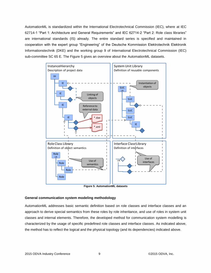
sub-committee SC 65 E. The Figure 5 gives an overview about the AutomationML datasets.
Figure 5: AutomationML datasets
General communication system modeling methodology AutomationML addresses basic semantic definition based on role classes and interface classes and an
approach to derive special semantics from these roles by role inheritance, and use of roles in system unit
classes and internal elements. Therefore, the developed method for communication system modelling is
characterized by the usage of specific predefined role classes and interface classes. As indicated above,
the method has to reflect the logical and the physical topology (and its dependencies) indicated above.
Interface Class LibraryDefinition of interfaces
System Unit LibraryDefinition of reusable components
InstanceHierarchyDescription of project data
Role Class LibraryDefinition of object semantics
IH
IE
SUC LIB
SUC
LIB
RoleLIB
Role
IE
IE
IE
IE
SUC
Role
Role
*.dae
*.xml
SUC
Reference toexternal data
Linking ofobjects
Instantiation ofobjects
Nutzen von Bedeutungen
Use ofsemantics
Nutzen von Bedeutungen
Use ofinterfaces
2015 ODVA Industry Conference 10 ©2015 ODVA, Inc.
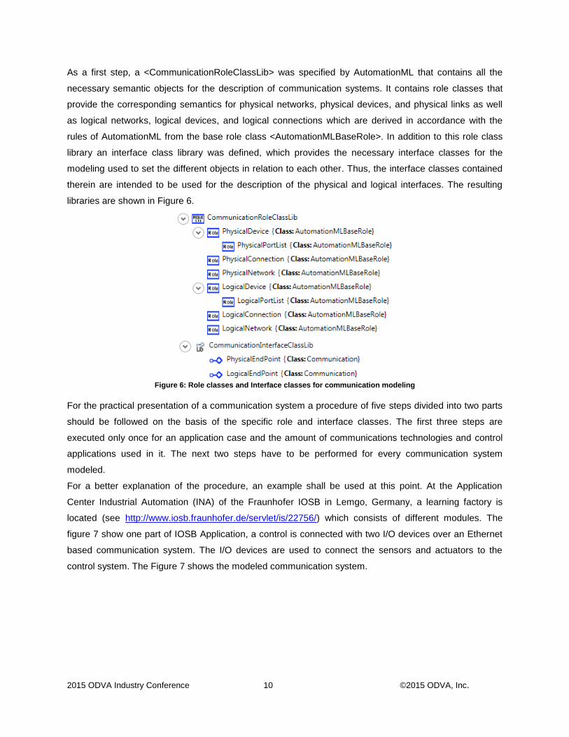
As a first step, a <CommunicationRoleClassLib> was specified by AutomationML that contains all the
necessary semantic objects for the description of communication systems. It contains role classes that
provide the corresponding semantics for physical networks, physical devices, and physical links as well
as logical networks, logical devices, and logical connections which are derived in accordance with the
rules of AutomationML from the base role class <AutomationMLBaseRole>. In addition to this role class
library an interface class library was defined, which provides the necessary interface classes for the
modeling used to set the different objects in relation to each other. Thus, the interface classes contained
therein are intended to be used for the description of the physical and logical interfaces. The resulting
libraries are shown in Figure 6.
Figure 6: Role classes and Interface classes for communication modeling
For the practical presentation of a communication system a procedure of five steps divided into two parts
should be followed on the basis of the specific role and interface classes. The first three steps are
executed only once for an application case and the amount of communications technologies and control
applications used in it. The next two steps have to be performed for every communication system
modeled.
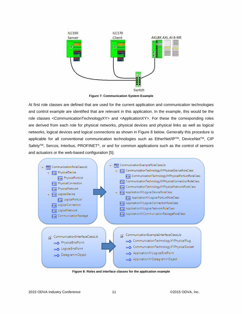
For a better explanation of the procedure, an example shall be used at this point. At the Application
Center Industrial Automation (INA) of the Fraunhofer IOSB in Lemgo, Germany, a learning factory is
located (see http://www.iosb.fraunhofer.de/servlet/is/22756/) which consists of different modules. The
figure 7 show one part of IOSB Application, a control is connected with two I/O devices over an Ethernet
based communication system. The I/O devices are used to connect the sensors and actuators to the
control system. The Figure 7 shows the modeled communication system.
2015 ODVA Industry Conference 11 ©2015 ODVA, Inc.
Figure 7: Communication System Example
At first role classes are defined that are used for the current application and communication technologies
and control example are identified that are relevant in this application. In the example, this would be the
role classes <CommunicationTechnologyXY> and <ApplicationXY>. For these the corresponding roles
are derived from each role for physical networks, physical devices and physical links as well as logical
networks, logical devices and logical connections as shown in Figure 8 below. Generally this procedure is
applicable for all conventional communication technologies such as EtherNet/IPTM, DeviceNetTM, CIP
SafetyTM, Sercos, Interbus, PROFINET®, or and for common applications such as the control of sensors
and actuators or the web-based configuration [5].
Figure 8: Roles and interface classes for the application example

2015 ODVA Industry Conference 12 ©2015 ODVA, Inc.
In the subsequent second step the interface classes have to be defined in the same way. Again, from the
interface classes appropriate technological and application-specific classes are derived that shall be used
later, see Figure 8 above.
Based on these role and interface classes, the physical devices, physical connections and the
corresponding logical devices and connections are modeled in appropriate system unit classes libraries
as system unit classes in the third step. To define the meaning of each component (each system unit
class) the role classes defined in the first step are used and for the connections among them the modeled
interface classes are used.
By doing so, in the example system named above three physical devices for the three control devices
each one with a physical interface, a physical device with six interfaces for the switch, and three logical
devices are the result. Similar classes result for connections which represent cables or radio links in case
of physical links. For the assignment of specific characteristics to the individual physical and logical
devices and connections as well as the interfaces located in the corresponding attributes are used.
Finally, for the communication data packages the relevant system unit classes shall be modeled
representing the exchanged sets of information on the logical connections.
The resulting system unit class libraries for the example are shown in Figure 9.
Figure 9: <SystemUnitClassLib> s for the application example
2015 ODVA Industry Conference 13 ©2015 ODVA, Inc.
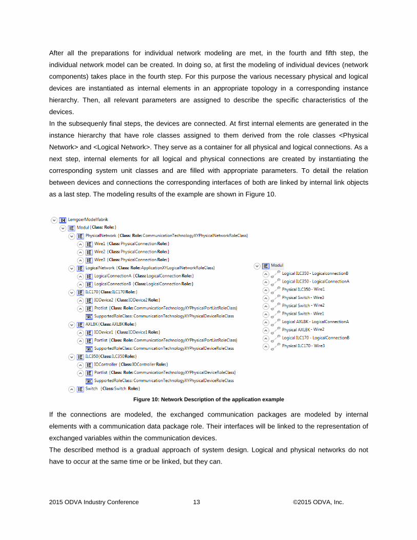
After all the preparations for individual network modeling are met, in the fourth and fifth step, the
individual network model can be created. In doing so, at first the modeling of individual devices (network
components) takes place in the fourth step. For this purpose the various necessary physical and logical
devices are instantiated as internal elements in an appropriate topology in a corresponding instance
hierarchy. Then, all relevant parameters are assigned to describe the specific characteristics of the
devices.
In the subsequenly final steps, the devices are connected. At first internal elements are generated in the
instance hierarchy that have role classes assigned to them derived from the role classes <Physical
Network> and <Logical Network>. They serve as a container for all physical and logical connections. As a
next step, internal elements for all logical and physical connections are created by instantiating the
corresponding system unit classes and are filled with appropriate parameters. To detail the relation
between devices and connections the corresponding interfaces of both are linked by internal link objects
as a last step. The modeling results of the example are shown in Figure 10.
Figure 10: Network Description of the application example
If the connections are modeled, the exchanged communication packages are modeled by internal
elements with a communication data package role. Their interfaces will be linked to the representation of
exchanged variables within the communication devices.
The described method is a gradual approach of system design. Logical and physical networks do not
have to occur at the same time or be linked, but they can.

2015 ODVA Industry Conference 14 ©2015 ODVA, Inc.
EtherNet/IPTM example As mentioned in the introduction the described modeling methodology for communication systems is
applied in a research and development project at Magdeburg University to support the technology
independent engineering of communication systems. Thereby, the project will cover communication
technologies ranging from simple protocols like ModbusTM on serial line up to powerful communication
technologies like EtherNet/IPTM. The intention is to cover the complete range of technologies applicable in
factory automation as well as energy generation and distribution.
EtherNet/IPTM has been selected deliberately as the involved engineers at Magdeburg University work
within the ODVA TestLab for Europe and the protocol is on the high end of sophistication within
communication technologies. It is expected that, if the EtherNet/IPTM Protocol can be modeled then the
modeling capabilities are proven to be sufficient for all other communication technologies.
The modeling of EtherNet/IPTM networks using AutomationML is considered in the following section. It will
be shown how the object architecture of EtherNet/IPTM is translated to relevant AutomationML modeling
entities, how communication data packages are represented, and how all modeling objects are used for
individual network modeling.
To make the following representation not too complex, a simple example is selected for further
consideration in this paper. It is based on a controller and a rotary encoder device connected within one
application (see Figure 11). Both devices are running a part of a control application using the rotation
information measured by the rotary encoder. Hence, they are connected by a logical connection (orange
in Figure 11) representing the information exchange and a physical connection (blue in Figure 11)
representing the physical wire among them.

2015 ODVA Industry Conference 15 ©2015 ODVA, Inc.
Figure 11: Example for an EtherNet/IP Network
Starting point of the modeling of EtherNet/IPTM networks is the creation of an EtherNet/IPTM role class
library. This library is derived from the basic communication library by inheriting the roles of the
AutomationML <CommunicationRoleClassLib> as depicted in Figure 12. These roles are enriched by
classic attributes for the different entities. Thereby, for example, the physical EtherNet/IPTM device will
have attributes for the MAC address as well as the IP address.
Figure 12 <RoleClassLib> of example Network
EthernetIP
Controller
Encoder
VAR Real NumberOfRevolutions ENDVAR
EthernetCable1
VAR Real Rotation ENDVAR
Control
application
Concoder
Profile
2015 ODVA Industry Conference 16 ©2015 ODVA, Inc.
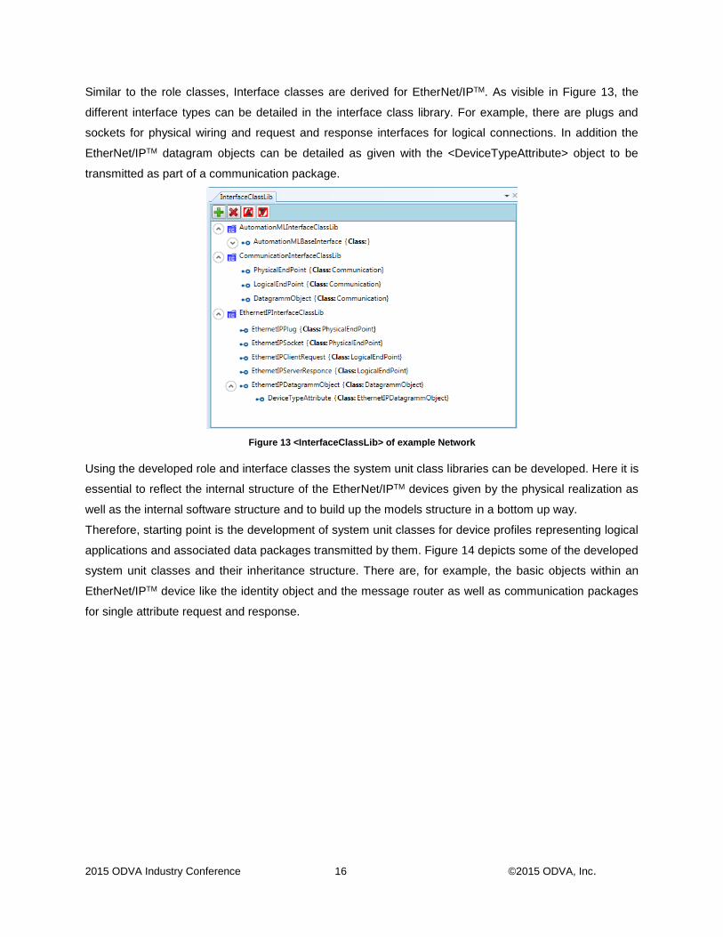
Similar to the role classes, Interface classes are derived for EtherNet/IPTM. As visible in Figure 13, the
different interface types can be detailed in the interface class library. For example, there are plugs and
sockets for physical wiring and request and response interfaces for logical connections. In addition the
EtherNet/IPTM datagram objects can be detailed as given with the <DeviceTypeAttribute> object to be
transmitted as part of a communication package.
Figure 13 <InterfaceClassLib> of example Network
Using the developed role and interface classes the system unit class libraries can be developed. Here it is
essential to reflect the internal structure of the EtherNet/IPTM devices given by the physical realization as
well as the internal software structure and to build up the models structure in a bottom up way.
Therefore, starting point is the development of system unit classes for device profiles representing logical
applications and associated data packages transmitted by them. Figure 14 depicts some of the developed
system unit classes and their inheritance structure. There are, for example, the basic objects within an
EtherNet/IPTM device like the identity object and the message router as well as communication packages
for single attribute request and response.

2015 ODVA Industry Conference 17 ©2015 ODVA, Inc.
Figure 14 <SystemUnitClassLib> of example network (Part 1)
Using these system unit classes more complex classes are developed using the defined objects as
internal structure. Figure 15 contains the developed EtherNet/IPTM explicit messaging encoder profile for
velocity information. It contains on the one hand interfaces enabling the assignment of logical connections
for client request and server response as well as the related communication packages.
Figure 15 <SystemUnitClassLib> of example network (Part 2)
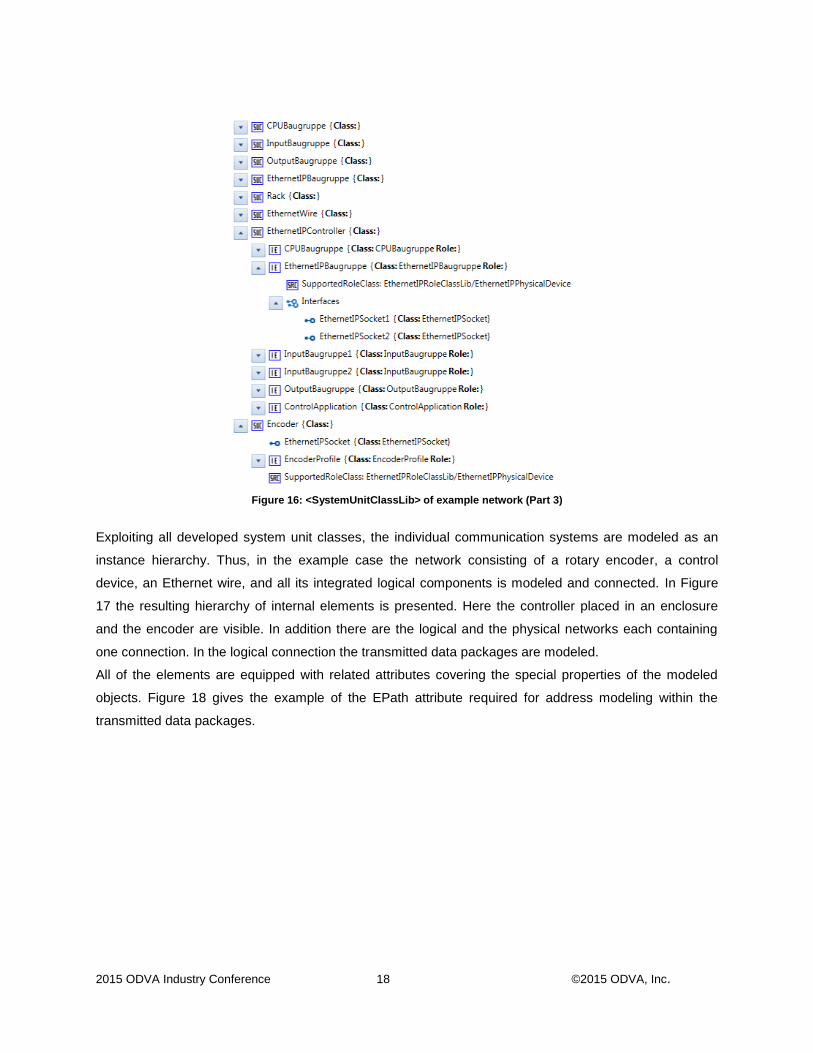
As next step the physical devices are modeled. Here the modular device structure of control devices is
reflected. The EtherNet/IPTM controller, as example, contains a rack, a CPU component, IO components,
etc. and a component reflecting the logical device (in this case the control application). Figure 16 reflects
the developed system unit classes.
2015 ODVA Industry Conference 18 ©2015 ODVA, Inc.
Figure 16: <SystemUnitClassLib> of example network (Part 3)
Exploiting all developed system unit classes, the individual communication systems are modeled as an
instance hierarchy. Thus, in the example case the network consisting of a rotary encoder, a control
device, an Ethernet wire, and all its integrated logical components is modeled and connected. In Figure
17 the resulting hierarchy of internal elements is presented. Here the controller placed in an enclosure
and the encoder are visible. In addition there are the logical and the physical networks each containing
one connection. In the logical connection the transmitted data packages are modeled.
All of the elements are equipped with related attributes covering the special properties of the modeled
objects. Figure 18 gives the example of the EPath attribute required for address modeling within the
transmitted data packages.

2015 ODVA Industry Conference 19 ©2015 ODVA, Inc.
Figure 17: <InstanceHierarchy> of example network
Figure 18: Attribute representing an EPath information
Summary and Outlook
2015 ODVA Industry Conference 20 ©2015 ODVA, Inc.
An important part in the engineering process of control systems is related to information representing
communication systems. In order to enable a lossless exchange of engineering data between different
engineering tools the AutomationML association has developed an AutomationML based method for
communication technology independent communication system representation.
This paper has presented this modeling methodology and has shown an example of its application based
on EtherNet/IPTM communication. It has been demonstrated that the described method is applicable in
principle.
Since the initial development of the modeling methodology by the AutomationML association different
pilot applications have been considered. Main lessons learned within these application cases are the
need of a detailed modeling of the involved communication devices in their physical and logical structure
including the representation of all related data to be exchanged and all related device properties, the
increasing complexity of resulting models, and the applicability of the created models for engineering and
installation assistance by automatic generation or artifacts out of the created models.
In sum all of the application cases have shown, that the developed modeling methodology is rich enough
to model all relevant engineering information.
Keywords engineering of automation technology, industrial communications, system models, AutomationML,
EtherNet/IPTM, neutral data format,
References: [1] acatech, “Recommendations for implementing the strategic initiative INDUSTRIE 4.0,” April 2013,
Report, http://www.plattform-i40.de/sites/default/files/Report_Industrie%204.0_engl_1.pdf
[2] T. Bauernhansl, M. ten Hompel, B. Vogel-Heuser (Hrsg.), “Industrie 4.0 in Produktion,
Automatisierung und Logistik,“ Springer, 2014.
[3] Lorenz Hundt, Arndt Lüder: Development of a method for the implementation of interoperable tool
chains applying mechatronical thinking – Use case engineering of logic control, 17th IEEE
International Conference on Emerging Technologies and Factory Automation (ETFA 2012),
Krakow, Polen, September 2012, Proceedings-CD.
[4] Hoffmann, M; Hundt, L; Fuchs: T.Seamless Engineering for Distributed Control Systems - An
Approach for Virtual Automation Networks, IEEE International Conference on Industrial
Technology, ICIT February 2009, Melbourne, Australia, Proceedings.
[5] F. Klasen, V. Oestreich, M. Volz: Industrielle Kommunikation mit Feldbus und Ethernet, VDE-
Verlag, 2010.
[6] Riedl, M.; Naumann, F.: EDDL – Electronic Device Description Language. Neuauflage,
Oldenbourg Verlag, 2011, ISBN 978-3-83563106-9.
2015 ODVA Industry Conference 21 ©2015 ODVA, Inc.
[7] Diedrich, Ch., Suchold, N.: Mechatronisches Anlagenmodell und die hybride Inbetriebnahme im
Konzept der digitalen Fabrik. In: AVILUS-Buch Virtuelle Techniken im industriellen Umfeld.
Springer 2011, ISBN-10: 3642206352.
[8] ISO 15745 – Industrial automation systems and integration — Open systems application
integration framework – Part 3: Reference description for IEC 61158-based control systems.
[9] R. Drath (Editor): Datenaustausch in der Anlagenplanung mit AutomationML, Springer Verlag,
2010.
[10] IEC 62714 - Engineering data exchange format for use in industrial automation systems
engineering - AutomationML,” www.iec.ch, International Electrotechnical Commission, 2014
[11] M. Schleipen, R. Drath, and O. Sauer, “The system-independent data exchange format CAEX for
supporting an automatic configuration of a production monitoring and control system,” in IEEE
International Symposium on Industrial Electronics (ISIE), 2008, pp. 1786–1791.
[12] Digital Asset and FX Exchange Schema, https://collada.org/, COLLADA, accessed: 2015-03.
[13] PLCopen for efficiency in autormation,” http://www.plcopen.org/, PLCopen, accessed: 2015-03.
[14] FDT Group,, “FDT – Field Device Tool,” http://www.fdtgroup.org, accessed 2015-09
****************************************************************************************************************************************************** The ideas, opinions, and recommendations expressed herein are intended to describe concepts of the author(s) for the possible use of ODVA technologies and do not reflect the ideas, opinions, and recommendation of ODVA per se. Because ODVA technologies may be applied in many diverse situations and in conjunction with products and systems from multiple vendors, the reader and those responsible for specifying ODVA networks must determine for themselves the suitability and the suitability of ideas, opinions, and recommendations expressed herein for intended use. Copyright ©2015 ODVA, Inc. All rights reserved. For permission to reproduce excerpts of this material, with appropriate attribution to the author(s), please contact ODVA on: TEL +1 734-975-8840 FAX +1 734-922-0027 EMAIL [email protected] WEB www.odva.org. CIP, Common Industrial Protocol, CIP Energy, CIP Motion, CIP Safety, CIP Sync, CompoNet, ControlNet, DeviceNet, and EtherNet/IP are trademarks of ODVA, Inc. All other trademarks are property of their respective owners.