excavation with old facades preservation
TRANSCRIPT

Excavation with old facades preservation
Critical analysis of the Jasmin Noir building
Freke De Roeck
Instituto Superior Técnico, Lisboa, Portugal
June 2018
Abstract
The increasing occupation of the urban underground space has consequences for existing buildings,
which often are not properly assessed when projects involving excavations and peripheral walls are
carried out. Thus, it is necessary to make studies and analysis addressing this issue, in order to provide
a scientific basis for the essentially empirical construction methods, which depend heavily on the
geological and geotechnical conditions. In this context, the thesis is focused on a construction work
called the ‘Jasmin Noir’ building in Lisbon, located at the Príncipe Real square - emphasizing retention
of facades to preserve and their underpinning as well as excavations and peripheral contention. An
underground car parking was performed using Munich type walls. An analysis of the displacements was
made through the finite element program PLAXIS 2D. Finally, two alternative solutions have been
studied to examine if the solution performed was possible to become optimized. In order to compare
their viability a technical and economic study was made.
KEYWORDS: Underpinning; Peripheral contention; Munich type walls; PLAXIS 2D; Alternative solutions.

2
1. Introduction As a Belgian Erasmus student, the opportunity
arose to study an excavation work in Lisbon city,
where the techniques used fit the content of the
dissertation and ranged from king post walls,
concrete slab bands, micropiles to retaining and
underpinning facades. In the thesis, the detailed
execution of some of these techniques is
described in greater detail. A general historical
overview of Lisbon and its rebuilding actions
after the Great Lisbon earthquake was made to
understand the seismic, geological and
geotechnical conditions situation in the capital
of Portugal. The case-study was analysed using
a Finite Element model, PLAXIS 2D, which
gave an overview of the expected deformation
of the soils and could be compared with the alert
and alarm criteria. Several companies who
design and develop geotechnical engineering
solutions are asked to propose other possible
solutions for the Jasmin Noir project. Belgian
and Portuguese companies have different
experience gathered through numerous
geotechnical projects, so they give different
solutions. These solutions are examined
technically, practically and economically for this
case study.
2. Lisbon’s great earthquake Through its history, Portugal mainland has
experienced the effects of various moderate to
strong earthquakes, thus presenting a
moderate seismic risk [1]. In 1755, a great
earthquake devastated Lisbon, destroying or
rendering uninhabitable most of the wealthy
city's buildings. This earthquake occurred in the
Kingdom of Portugal on Saturday, 1 November
1755, the Catholic holiday of All Saints’ Day, at
around 9:40 a.m. On this day the deeply
religious Portuguese packed Lisbon's churches
and cathedrals to celebrate the important feast
day. As part of the religious celebrations every
possible candle was lit and the churches were
decorated with flowers and flammable
decorations. There were three distinct quake
shocks over a ten minute period, which made
the candles tumble and ignited the flowers.
These fires ravaged Lisbon for five further days
after the earthquake. Approximately 40 minutes
after the earthquake, a tsunami engulfed the
harbour and downtown area, rushing up the
Tagus river. This first tsunami wave was
followed by two more waves which hit the shore.
[1] Eighty-five percent of Lisbon's buildings
were destroyed, including famous palaces and
libraries, as well as most examples of Portugal's
distinctive 16th-century Manueline architecture.
Several buildings that had suffered little
earthquake damage were destroyed by the
subsequent fire. Because most of the effects of
the offshore quake were caused by the massive
tsunami and widespread fires that followed,
rather than by ground shaking, it was believed
that were a similar event to occur today, modern
tsunami warning systems and disaster
response practices, as well as superior building
construction, would moderate the scale of
damage and casualty. The geotechnical soil
characterization is of the utmost importance for
seismic risk assessment, being used, in
particular, for site effect assessment. They
depend mainly on the geological, geotechnical
and topographic site characteristics. The large
number of old masonry buildings present the
most significant potential for large loss
earthquakes in Lisbon. [2]
3. Lisbon rebuilding actions and
plans Three typologies of masonry buildings are
usually recognized in the Lisbon County:
Pombalino buildings built after the 1755
earthquake and systematically imposed during
the whole reconstruction program, Gaioleiro
buildings built with inferior constructive quality
between 1870 and 1930 and Placa buildings, a
short-term structural solution which precedes
the reinforced concrete buildings [3]. The
Pombalino construction represents the first time
in history that a city was entirely built making
use of solutions designed to withstand future
earthquakes. The new downtown design placed
the buildings in rectangular quarters with similar
dimension following an orthogonal grid of
streets. According to Mascarenhas (2005), the
structural regularity of the buildings provided a
similar performance of the construction within
the compound, which besides reinforcing the
group effect also gave them superior structural
stability. Vertical and horizontal timber elements
were added to the facade walls, stiffening the
masonry structure around the window
openings. The interior structure was composed
by timber-masonry walls, timber floors and roof,

3
linked to the exterior walls by timber connecters
partially embedded on the masonry and
reinforced by metal straps. The wood structure
results on the buildings strength and energy
dissipation capacity, essential to support the
seismic actions in any direction [4]. The
existence of the three-dimensional timber
structure is named ‘gaiola pombalina’. The
principal structural material is not only masonry
but also wood elements that exist wrapped up
in it like a cage made of vertical and horizontal
elements braced with diagonals, enclosed on
the walls above the first storey. These diagonal
elements form Saint Andrew’s Crosses, which
allow forces redistribution from horizontal
actions. The wooden cage is the main
earthquake resisting system, eventually leaving
masonry to a secondary role. It is known that the
mass of a building plays an important role
regarding the seismic effects, thus, a timber
structure would drastically reduce the weight of
the building which combined with the cross
timber members conferred an increased
resistance that could not possibly be achieved
with a simple masonry wall [5]. The Gaioleiro
buildings were aggregated in quarters with
interior yards and surrounded by a grid of
secondary streets, wider than the streets of the
Pombalino downtown. There were no standards
for buildings height or depth, neither for the
architectural design of the facade walls. The
construction was carried out by private entities,
and therefore the quality of the buildings is very
variable. During the nineteenth century, the
cage structure characteristic of the Pombalino
buildings was progressively simplified. The
diagonal elements started to be removed,
conditioning the bracing of the timber structure
and the rubble infill was then replaced by brick
masonry, solid on the lower floors and hollow on
the upper. In 1938, a new urbanization plan was
commissioned by engineer Duarte Pacheco.
The first buildings were built with exterior
masonry walls and timber floors strengthened
by peripheral concrete beams. The concrete
slabs were extended to the whole floor,
supporting the name ‘Placa’ (meaning concrete
slab) given to this typology of buildings [6].
4. Munich type walls When King Post walls are structures which
consist of metal profiles with between them,
profiles of wood or precast concrete panels [7],
these types of retaining walls are temporary and
they are called Berliner walls. Although, when
the execution of the walls is a permanent
solution that uses reinforced concrete poured in
site, supported by micropiles staled at the
ground vertically, this technique is called
Munich walls. These walls can be used as the
final wall of an underground floor. The name of
these techniques has already led to some
controversy, because they are similar but
definitely not the same. The use of Munich-type
walls is a solution widely used nowadays in
buildings where is expected to maintain its
facade, since it presents several advantages
over other solutions [8]. For the execution of
Munich-type walls, first a general excavation
has to be executed, just up to the bottom of the
crown beam. This should be as low as possible,
dependent on the conditions of the project.
Then, the micropiles can be installed vertically
and the crown beam can be made. The crown
beam makes sure that the remaining loads of
the building can be transferred to the micropiles.
Therefore, the crown beam connects the
micropiles to the remaining structure of the
building. Just like the execution of the Berliner
wall, the execution of the Munich-type wall is
done in vertical stages. But here the use of
horizontal staging is also important, because of
the ‘Soil-arching effect’. Horizontal stages
usually have a width of 1m to 1,5m. In this
alternate panel method, primary panels shall be
cast first, leaving suitable gaps in between.
These gaps are excavations made in a slope for
an optimal soil-arching effect. Secondary
panels shall then be cast, resulting in a
continuous Munich wall. Each stage consists of
the placement of the reinforcement and
formwork, followed by pouring the concrete.
The crown beam has the objective of joining all
the profiles so they can work together.

4
Figure 1: Munich type walls
5. Case study – Jasmin Noir
building This case study is about an excavation site with
the preservation of the old facades. The ‘Jasmin
Noir’ building was built more than hundred
years ago and is not liveable anymore. The
facades must be preserved as a request of the
Lisbon Municipality and there will be an
excavation because the basement will become
a place for two parking lots.
Figure 2: Jasmin Noir building front facade
Figure 3: Jasmin Noir building rear façade
Figure 4: Shoring upper floors
Figure 5: Shoring basement floor
Figure 6: Micropiles

5
5.1 Geotechnical and geological
information
ATTITUDE, S.A. requested Tecnasol FGE to do
geotechnical tests of the building’s area to
recognize its characteristics. They did this using
two drill holes that allowed to identify the soils
that occurred, followed by dynamic SPT
penetration tests (Standard Penetration Test).
For the identification of the base and geometry
of the lateral wall foundations in the backyard of
the building, two inspection wells P1 and P2
were made. From the interpretation of the
described tests, it was possible to establish the
existence of four geological units (ZG1, ZG2,
ZG3 and ZG4). These geological units are
described by the parameters presented in Table
1.
Table 1: Geotechnical parameters
Zone Description ᵧ (kN/m³)
Ø (°) C
(kPa)
E
(MPa)
ZG4 Landfills 10-
14
15-
20 0
2,5*
3,5**
ZG3 Clays with
silt
19-
21
30-
33
22-
50
16,5-
18,7*
23-
26**
ZG2
Clays with
silt,
sometimes
with marls
20-
21
34-
36
50-
110
24-
34*
33-
48**
ZG1
Clays with
silt and silt
with clay
21-
22
35-
40
100-
150
45*
60**
* Assymetric loading
** Flat deformation
5.2 Modelling in PLAXIS 2D
Geotechnical applications require advanced
constitutive models for the simulation of the
non-linear, time-dependent and anisotropic
behaviour of soils and/or rock. PLAXIS 2D is a
finite element program, developed for the
analysis of deformation, stability and
groundwater flow in geotechnical engineering.
With Staged Construction the software can
accurately model the construction process, by
activating and deactivating soil clusters and
structural elements in each calculation phase.
With plastic, consolidation and safety analysis
calculation type, a broad range of geotechnical
problems can be analysed. The soil model that
is recommended to describe the layers of the
ground in excavations of this type is the
Hardening-Soil. This model simulates a realistic
way the soils behave, using three stiffness’ to
characterize the soil, E50, Eur, and Eoed, Only the
behaviour of one section was modelled and
analysed, the one where the excavation is the
deepest, which is at the section closest to the
front façade. After defining the geometry of the
model, the input set has the appearance shown
in Figure 7.
Figure 7: input PLAXIS
Using the data contained in mechanical
boreholes, geological and geotechnical reports,
technical notes and some correlations between
parameters, the four distinct layers of soil were
defined. In table 2 are the parameters used to
characterize the soils.

6
Table 2: Used parameters for the hardening-soil
model
In the subroutine ‘Calculate’ it is necessary to
characterize the various stages of the
construction of the earth retaining wall, trying to
reproduce as closely as possible what happens
in reality.
The calculation stages are briefly presented
below:
• Phase 0: initial phase;
• Phase 1: external load;
• Phase 2: micropiles;
• Phase 3: first slab;
• Phase 4: first level excavation (2,86m);
• Phase 5: first level Munich walls
(ΣMstage = 0.7) (2,86m);
• Phase 6: first level Munich walls
(ΣMstage = 0.3) (2,86m);
• Phase 7: second slab;
• Phase 8: second level excavation
(2,74m);
• Phase 9: second level Munich walls
(ΣMstage = 0.7) (2,74m);
• Phase 10: second level Munich walls
(ΣMstage = 0.3) (2,74m); Phase 11: third slab;
• Phase 12: third level excavation
(2,35m);
• Phase 13: third level Munich walls
(ΣMstage = 0.7) (2,35m);
• Phase 14: third level Munich walls
(ΣMstage = 0.3) (2,35m);
• Phase 15: fourth level excavation
(2,60m);
• Phase 16: fourth level Munich walls
(ΣMstage = 0.7) (2,60m);
• Phase 17: fourth level Munich walls
(ΣMstage = 0,3) (2,60m).
After the characterization of each phase, the
model was run, yielding efforts and final
displacements, which serve as reference for the
design of the solution and prediction of actual
results in terms of displacements.
Figure 8: Results PLAXIS
According to Figure 8, it can be seen that the
maximum horizontal displacement occurs
behind the pile curtain, under the adjacent
building. This horizontal displacement is in the
direction of the interior of the excavation and
has a maximum value of approximately 18 mm.
This is 3mm more than the admissible value, but
is not an alarm criteria. However, experience
has shown that this deformation value is
considerably higher than those that happen in
reality. The maximum vertical displacements
Parameters Geotechnical zones
Hardening-
soil model ZG4 ZG3 ZG2 ZG1
ᵧunsat
[KN/m³] 10 19 20 21
ᵧsat [KN/m³] 14 21 21 22
einit 0,5 0,5 0,5 0,5
Eref50 [KN/m²] 3500 24500 40500 60000
Erefur [KN/m²] 10500 73500 121500 180000
Erefoed[KN/m²] 3500 24500 40500 60000
cref [KN/m²] 0 36 80 125
nuur 0,2 0,2 0,2 0,2
Φ [°] 17,5 31,5 35 37,5
Ψ [°] 0 0 0 0
Rinter 1 1 1 1
Rf 0,9 0,9 0,9 0,9
pref [KN/m²] 100 100 100 100
m 0,7 0,7 0,7 0,7
K0 0,5 0,5 0,5 0,5

7
occur under the neighbouring building,
corresponding to settlements of 76 mm. This is
because of the load of the building, not because
of the excavation. The upper layer of the soil will
settle under the load because the foundations
of the adjacent buildings are not modelled. At
the base of the excavation and next to the
curtain wall, there is a displacement of about 8
mm. This is lower than 10mm, the admissible
value.
6. Alternative solutions
6.1 Underpinning in a contained slot
Munich type walls are an easy, cheap
containment method which can be executed
against the soil. This is a very common used
technique in Portugal, but isn’t used like this is
other countries. In Belgium there’s a very
common used method with almost the same
advantages, but there are some differences. As
far as the stability of the upper structure allows
it, a pre-excavation is realized with a minimum
of 0,50m above the existing foundation that
should be kept. The excavation of the slot will
happen in horizontal phases, like the Munich
type walls, to avoid the soil-arching effect to
damage the structure of adjacent buildings. The
width of these horizontal strips is usually 1m,
while the sloth has a length of 1,5 to 2m, which
makes it possible to carry out the excavation
work with sufficient room for manoeuvre. The
soil is excavated in vertical stages of 0,4m while
systematically applying formwork over the
entire perimeter of the pit. The wall that is under
the existing foundation is covered with lost
prefabricated concrete elements. The other
three sides are temporarily covered (for
example with wood). The evacuation of the
excavated soil is usually done with the help of a
bucket lift. This process is repeated until the
predetermined depth is reached. After the
completion of the excavation process, a
reinforcement is placed first and then the
formwork of the front side of the wall is put in
place. Eventually the concrete can be poured.
These first phase strips have to harden for a
couple of days, before the second phase can
start. This second phase follows the same
steps, but the prefabricated concrete formwork
has to be placed behind the ones of the first
phase, so a continuous wall is created.
Figure 9: Underpinning in a contained slot
Considering the construction pit reaches a
depth of more than 10m in certain locations of
the Jasmin Noir site, the safety aspect is very
important in this case. In Belgium they still use
this technique, usually for underpinning cases
of 3-6m, although depths of more than 15m are
also possible. Sufficient attention must be paid
to dimensioning and implementation, since
careless realization can entail major risks. For
this reason, the technique hasn’t been used in
Portugal for a lot of years and especially in this
case, the safety of the employees must be
guaranteed. On top of that, the execution of this
technique would take a long time because it’s a
manual excavation which exists out of a lot of
stages.
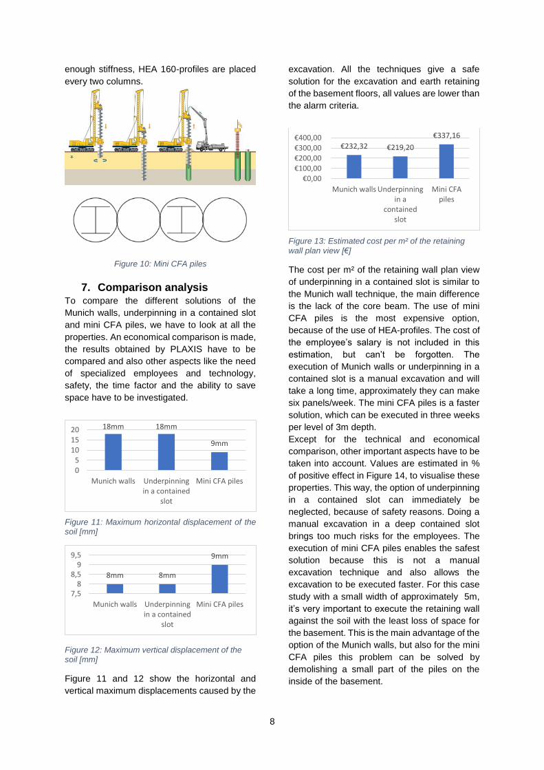
6.2 Mini CFA piles
Mini CFA piles can be made out of micro
concrete with HEA-profiles and have a smaller
diameter as usual. CFA piles are typically
installed with diameters ranging from 0,3 to 0,9
m, while the mini CFA piles have a diameter of
250mm and are constructed with the same
machine as micropiles. CFA piles are a type of
drilled foundation in which the pile is drilled to
the final depth in one continuous process using
a continuous flight auger. While the auger is
drilled into the ground, the flights of the auger
are filled with soil, providing lateral support and
maintaining the stability of the hole. At the same
time the auger is withdrawn from the hole,
concrete or a sand/cement grout is placed by
pumping the concrete/grout mix through the
hollow center of the auger pipe to the base of
the auger. Simultaneous pumping of the grout
or concrete and withdrawing of the auger
provides continuous support of the hole. To
create a continuous earth retaining wall with
8
enough stiffness, HEA 160-profiles are placed
every two columns.
Figure 10: Mini CFA piles
7. Comparison analysis To compare the different solutions of the
Munich walls, underpinning in a contained slot
and mini CFA piles, we have to look at all the
properties. An economical comparison is made,
the results obtained by PLAXIS have to be
compared and also other aspects like the need
of specialized employees and technology,
safety, the time factor and the ability to save
space have to be investigated.
Figure 11: Maximum horizontal displacement of the soil [mm]
Figure 12: Maximum vertical displacement of the soil [mm]
Figure 11 and 12 show the horizontal and
vertical maximum displacements caused by the
excavation. All the techniques give a safe
solution for the excavation and earth retaining
of the basement floors, all values are lower than
the alarm criteria.
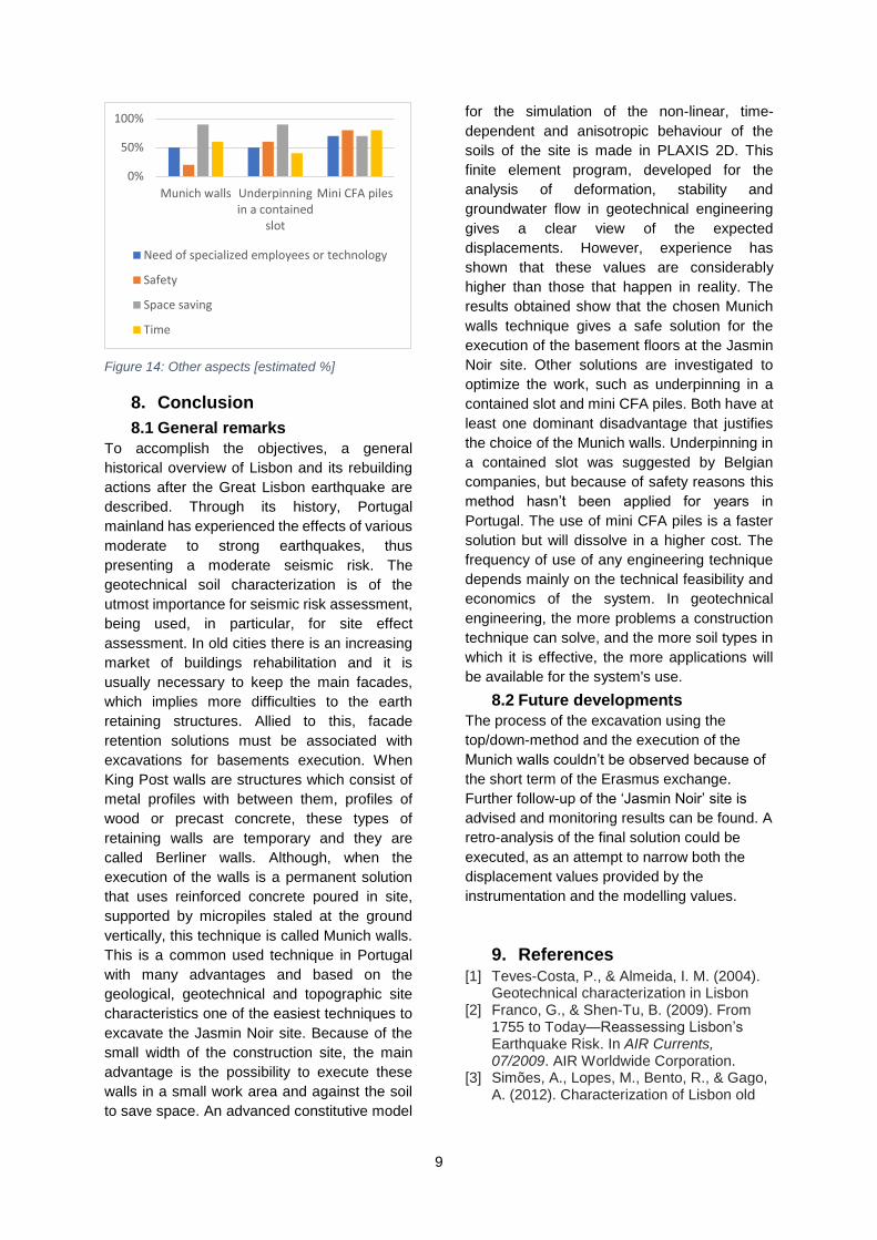
Figure 13: Estimated cost per m² of the retaining
wall plan view [€]
The cost per m² of the retaining wall plan view
of underpinning in a contained slot is similar to
the Munich wall technique, the main difference
is the lack of the core beam. The use of mini
CFA piles is the most expensive option,
because of the use of HEA-profiles. The cost of
the employee’s salary is not included in this
estimation, but can’t be forgotten. The
execution of Munich walls or underpinning in a
contained slot is a manual excavation and will
take a long time, approximately they can make
six panels/week. The mini CFA piles is a faster
solution, which can be executed in three weeks
per level of 3m depth.
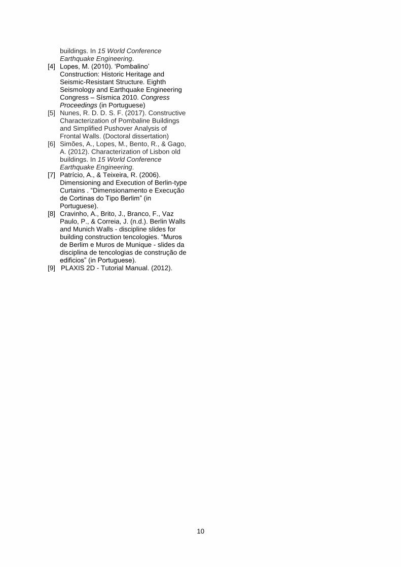
Except for the technical and economical
comparison, other important aspects have to be
taken into account. Values are estimated in %
of positive effect in Figure 14, to visualise these
properties. This way, the option of underpinning
in a contained slot can immediately be
neglected, because of safety reasons. Doing a
manual excavation in a deep contained slot
brings too much risks for the employees. The
execution of mini CFA piles enables the safest
solution because this is not a manual
excavation technique and also allows the
excavation to be executed faster. For this case
study with a small width of approximately 5m,
it’s very important to execute the retaining wall
against the soil with the least loss of space for
the basement. This is the main advantage of the
option of the Munich walls, but also for the mini
CFA piles this problem can be solved by
demolishing a small part of the piles on the
inside of the basement.
18mm 18mm
9mm
05
101520
Munich walls Underpinningin a contained
slot
Mini CFA piles
8mm 8mm
9mm
7,58
8,59
9,5
Munich walls Underpinningin a contained
slot
Mini CFA piles
€232,32 €219,20
€337,16
€0,00 €100,00 €200,00 €300,00 €400,00
Munich walls Underpinningin a
containedslot
Mini CFApiles
9
Figure 14: Other aspects [estimated %]
8. Conclusion
8.1 General remarks
To accomplish the objectives, a general
historical overview of Lisbon and its rebuilding
actions after the Great Lisbon earthquake are
described. Through its history, Portugal
mainland has experienced the effects of various
moderate to strong earthquakes, thus
presenting a moderate seismic risk. The
geotechnical soil characterization is of the
utmost importance for seismic risk assessment,
being used, in particular, for site effect
assessment. In old cities there is an increasing
market of buildings rehabilitation and it is
usually necessary to keep the main facades,
which implies more difficulties to the earth
retaining structures. Allied to this, facade
retention solutions must be associated with
excavations for basements execution. When
King Post walls are structures which consist of
metal profiles with between them, profiles of
wood or precast concrete, these types of
retaining walls are temporary and they are
called Berliner walls. Although, when the
execution of the walls is a permanent solution
that uses reinforced concrete poured in site,
supported by micropiles staled at the ground
vertically, this technique is called Munich walls.
This is a common used technique in Portugal
with many advantages and based on the
geological, geotechnical and topographic site
characteristics one of the easiest techniques to
excavate the Jasmin Noir site. Because of the
small width of the construction site, the main
advantage is the possibility to execute these
walls in a small work area and against the soil
to save space. An advanced constitutive model
for the simulation of the non-linear, time-
dependent and anisotropic behaviour of the
soils of the site is made in PLAXIS 2D. This
finite element program, developed for the
analysis of deformation, stability and
groundwater flow in geotechnical engineering
gives a clear view of the expected
displacements. However, experience has
shown that these values are considerably
higher than those that happen in reality. The
results obtained show that the chosen Munich
walls technique gives a safe solution for the
execution of the basement floors at the Jasmin
Noir site. Other solutions are investigated to
optimize the work, such as underpinning in a
contained slot and mini CFA piles. Both have at
least one dominant disadvantage that justifies
the choice of the Munich walls. Underpinning in
a contained slot was suggested by Belgian
companies, but because of safety reasons this
method hasn’t been applied for years in
Portugal. The use of mini CFA piles is a faster
solution but will dissolve in a higher cost. The
frequency of use of any engineering technique
depends mainly on the technical feasibility and
economics of the system. In geotechnical
engineering, the more problems a construction
technique can solve, and the more soil types in
which it is effective, the more applications will
be available for the system's use.
8.2 Future developments
The process of the excavation using the
top/down-method and the execution of the
Munich walls couldn’t be observed because of
the short term of the Erasmus exchange.
Further follow-up of the ‘Jasmin Noir’ site is
advised and monitoring results can be found. A
retro-analysis of the final solution could be
executed, as an attempt to narrow both the
displacement values provided by the
instrumentation and the modelling values.
9. References [1] Teves-Costa, P., & Almeida, I. M. (2004).
Geotechnical characterization in Lisbon [2] Franco, G., & Shen-Tu, B. (2009). From
1755 to Today—Reassessing Lisbon’s Earthquake Risk. In AIR Currents, 07/2009. AIR Worldwide Corporation.
[3] Simões, A., Lopes, M., Bento, R., & Gago, A. (2012). Characterization of Lisbon old
0%
50%
100%
Munich walls Underpinningin a contained
slot
Mini CFA piles
Need of specialized employees or technology
Safety
Space saving
Time
10
buildings. In 15 World Conference Earthquake Engineering.
[4] Lopes, M. (2010). ‘Pombalino’ Construction: Historic Heritage and Seismic-Resistant Structure. Eighth Seismology and Earthquake Engineering Congress – Sísmica 2010. Congress Proceedings (in Portuguese)
[5] Nunes, R. D. D. S. F. (2017). Constructive Characterization of Pombaline Buildings and Simplified Pushover Analysis of Frontal Walls. (Doctoral dissertation)
[6] Simões, A., Lopes, M., Bento, R., & Gago, A. (2012). Characterization of Lisbon old buildings. In 15 World Conference Earthquake Engineering.
[7] Patrício, A., & Teixeira, R. (2006). Dimensioning and Execution of Berlin-type Curtains . “Dimensionamento e Execução de Cortinas do Tipo Berlim” (in Portuguese).
[8] Cravinho, A., Brito, J., Branco, F., Vaz Paulo, P., & Correia, J. (n.d.). Berlin Walls and Munich Walls - discipline slides for building construction tencologies. “Muros de Berlim e Muros de Munique - slides da disciplina de tencologias de construção de edificios” (in Portuguese).
[9] PLAXIS 2D - Tutorial Manual. (2012).