examples of stormwater control devices - · pdf filefiltration basin a shallow basin with ......
TRANSCRIPT

Stormwater Control Devices
Filtration Basin A SHALLOW BASIN WITH ENGINEERED OR AMENDED SOIL
AND AN UNDERDRAIN SYSTEM
Filtration basins function by detaining stormwater in the basin. As stormwater infiltrates through the amended soil, sand, or engineered media, pollutants are filtered and adsorbed onto soil particles. Treated stormwater is directed to the receiving stream via the underdrain system.
� Filtration basins may be shaped like ponds or
channels. � To improve pollutant removal, the basin may be
covered with grass, wetland species, or landscaped vegetation (see Bioretention Basin).
� Sand filters are considered filtration basins. � Filtration basins may have outlet control structures
and emergency spillways. However, all filtration basins have underdrain systems.
Bioretention Basin A TYPE OF FILTRATION BASIN WITH ENGINEERED MEDIA, AN UNDERDRAIN SYSTEM, AND LANDSCAPED VEGETATION
Bioretention basins use a landscaped mix of water-tolerant plants to improve pollutant removal. The vegetation is selected for its ability to physically filter and uptake stormwater pollutants. As with all filtration basins, stormwater is infiltrated through amended soil or an engineered media before it enters the underdrain system. � Selected vegetation simulates various ecosystems
such as forests, meadows, and hedgerows � Bioretention basins are suited to drainage areas
less than 1 acre. � Bioretention basins may include outlet control
structures and emergency spillways, but they will always have underdrain systems.

Dry Detention Basin A SHALLOW, DRY BASIN WITH AN OUTLET PIPE OR ORIFICE
AT THE INVERT OF THE BASIN
Dry detention basins attenuate peak discharges and temporarily detain runoff to promote sedimentation of solids and infiltration. Runoff is slowly released from an outlet control structure at a steady flow rate to increase detention time.
� Dry detention basins may be shaped like ponds or
channels. � The primary outlet control structure is located at
the invert of the basin, allowing stormwater to drain slowly and completely between storm events.
� Dry detention basins are identified by the presence of an outlet control structure and an emergency spillway.
Wet Detention Basin A SHALLOW BASIN THAT MAINTAINS A PERMANENT POOL
OF WATER BY USING AN ELEVATED OUTLET CONTROL
STRUCTURE
Wet detention basins treat stormwater through sedimentation and biological uptake of pollutants by plants, algae, and bacteria. Stormwater runoff in excess of the permanent pool is slowly released from the basin to prevent downstream erosion.
� Wet detention basins may be shaped like ponds or channels.
� The outlet control structure is elevated above the invert of the basin, allowing pollutant-laden solids to settle to the bottom and cleaner surface water to exit.
� The wet detention basin may have additional capacity for detaining and slowly releasing volumes greater than the permanent pool volume.
� Wet detention basins contain an emergency spillway to convey large events.
� Vegetation growing around the perimeter of the basin provides for biological uptake of nutrients.
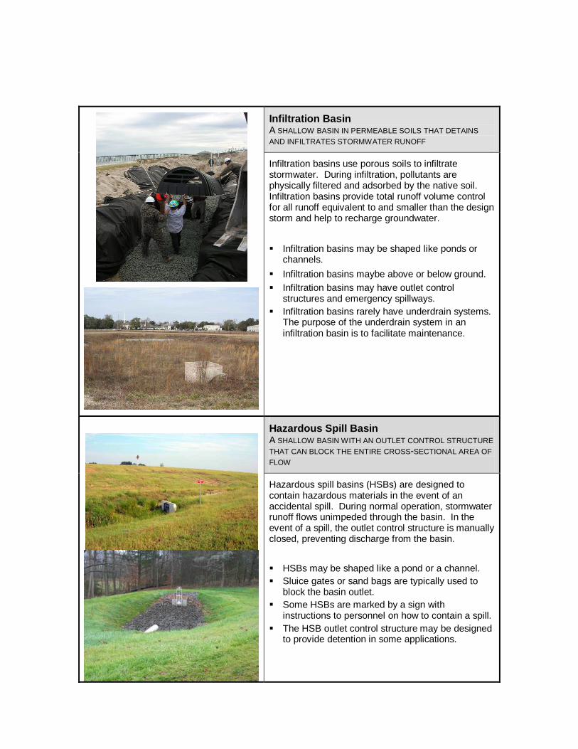
Infiltration Basin A SHALLOW BASIN IN PERMEABLE SOILS THAT DETAINS
AND INFILTRATES STORMWATER RUNOFF
Infiltration basins use porous soils to infiltrate stormwater. During infiltration, pollutants are physically filtered and adsorbed by the native soil. Infiltration basins provide total runoff volume control for all runoff equivalent to and smaller than the design storm and help to recharge groundwater.
� Infiltration basins may be shaped like ponds or channels.
� Infiltration basins maybe above or below ground. � Infiltration basins may have outlet control
structures and emergency spillways. � Infiltration basins rarely have underdrain systems.
The purpose of the underdrain system in an infiltration basin is to facilitate maintenance.
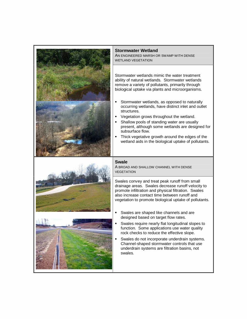
Hazardous Spill Basin A SHALLOW BASIN WITH AN OUTLET CONTROL STRUCTURE
THAT CAN BLOCK THE ENTIRE CROSS-SECTIONAL AREA OF
FLOW
Hazardous spill basins (HSBs) are designed to contain hazardous materials in the event of an accidental spill. During normal operation, stormwater runoff flows unimpeded through the basin. In the event of a spill, the outlet control structure is manually closed, preventing discharge from the basin.
� HSBs may be shaped like a pond or a channel. � Sluice gates or sand bags are typically used to
block the basin outlet. � Some HSBs are marked by a sign with
instructions to personnel on how to contain a spill. � The HSB outlet control structure may be designed
to provide detention in some applications.
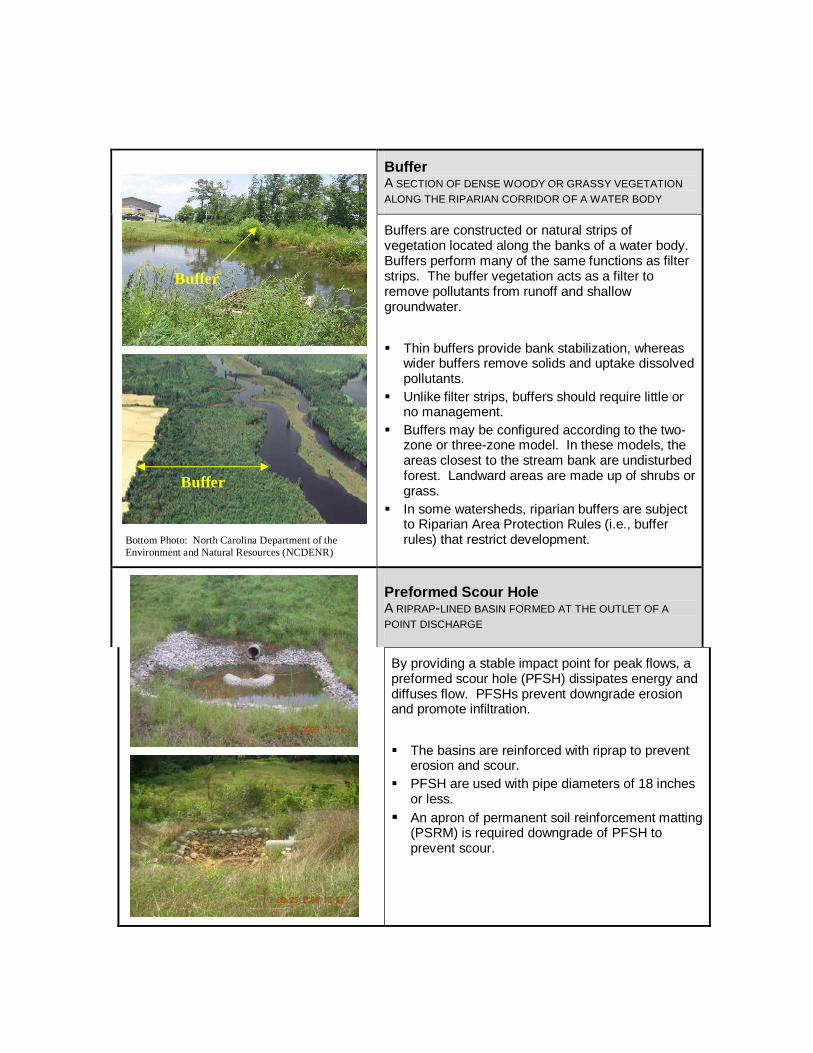
Stormwater Wetland AN ENGINEERED MARSH OR SWAMP WITH DENSE
WETLAND VEGETATION
Stormwater wetlands mimic the water treatment ability of natural wetlands. Stormwater wetlands remove a variety of pollutants, primarily through biological uptake via plants and microorganisms.
� Stormwater wetlands, as opposed to naturally
occurring wetlands, have distinct inlet and outlet structures.
� Vegetation grows throughout the wetland. � Shallow pools of standing water are usually
present, although some wetlands are designed for subsurface flow.
� Thick vegetative growth around the edges of the wetland aids in the biological uptake of pollutants.
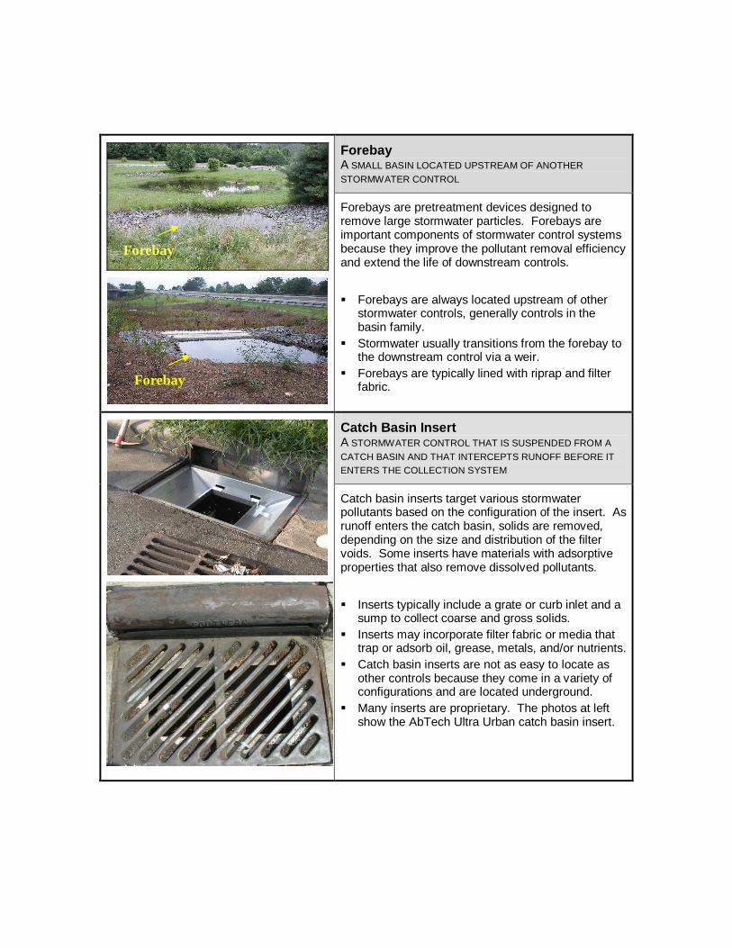
Swale A BROAD AND SHALLOW CHANNEL WITH DENSE
VEGETATION
Swales convey and treat peak runoff from small drainage areas. Swales decrease runoff velocity to promote infiltration and physical filtration. Swales also increase contact time between runoff and vegetation to promote biological uptake of pollutants.
� Swales are shaped like channels and are
designed based on target flow rates.
� Swales require nearly flat longitudinal slopes to function. Some applications use water quality rock checks to reduce the effective slope.
� Swales do not incorporate underdrain systems. Channel-shaped stormwater controls that use underdrain systems are filtration basins, not swales.

Level Spreader A TROUGH AND LEVEL LIP USED TO REDISTRIBUTE
CONCENTRATED STORMWATER AS DIFFUSE FLOW
Level spreaders provide a nonerosive outlet for concentrated runoff by diffusing the water uniformly across a stable slope.
� Level spreaders are implemented upstream of
buffers, swales, and basins to improve infiltration and biological uptake.
� Level spreaders are implemented downstream of stormwater controls to prevent stormwater from reconcentrating.
� Level spreaders are implemented on nearly flat grades to prevent reconcentration of runoff.
� The length of the level spreader trough will vary, depending on the stormwater discharge rate.
Filter Strip A LINEAR SECTION OF LAND, EITHER GRASSED OR
FORESTED, THAT PHYSICALLY FILTERS AND INFILTRATES
STORMWATER.
Filter strips intercept perpendicular, diffuse flow, much the same way a buffer does. As runoff enters the filter strip, dense foliage and thick root mats physically filter out solids while reducing the peak flow rate.
� Runoff must be in the form of diffuse flow for filter
strips to function. Filter strips are often located downstream of level spreaders and preformed scour holes.
� Filter strips may consist of tree stands, shrubs, grass, or a combination thereof.
� Filter strips may be located along the perimeter of a water bodies as well as nonriparian areas.
� Unlike buffers, filter strips are regularly managed through mowing, trimming, and replanting.
Level Spreader
Level Spreader
Filter Strip
Filter Strip
Buffer A SECTION OF DENSE WOODY OR GRASSY VEGETATION
ALONG THE RIPARIAN CORRIDOR OF A WATER BODY
Bottom Photo: North Carolina Department of the Environment and Natural Resources (NCDENR)
Buffers are constructed or natural strips of vegetation located along the banks of a water body. Buffers perform many of the same functions as filter strips. The buffer vegetation acts as a filter to remove pollutants from runoff and shallow groundwater.
� Thin buffers provide bank stabilization, whereas
wider buffers remove solids and uptake dissolved pollutants.
� Unlike filter strips, buffers should require little or no management.
� Buffers may be configured according to the two-zone or three-zone model. In these models, the areas closest to the stream bank are undisturbed forest. Landward areas are made up of shrubs or grass.
� In some watersheds, riparian buffers are subject to Riparian Area Protection Rules (i.e., buffer rules) that restrict development.
Preformed Scour Hole A RIPRAP-LINED BASIN FORMED AT THE OUTLET OF A
POINT DISCHARGE
By providing a stable impact point for peak flows, a preformed scour hole (PFSH) dissipates energy and diffuses flow. PFSHs prevent downgrade erosion and promote infiltration.
� The basins are reinforced with riprap to prevent
erosion and scour. � PFSH are used with pipe diameters of 18 inches
or less. � An apron of permanent soil reinforcement matting
(PSRM) is required downgrade of PFSH to prevent scour.
Buffer
Buffer
Forebay A SMALL BASIN LOCATED UPSTREAM OF ANOTHER
STORMWATER CONTROL
Forebays are pretreatment devices designed to remove large stormwater particles. Forebays are important components of stormwater control systems because they improve the pollutant removal efficiency and extend the life of downstream controls.
� Forebays are always located upstream of other
stormwater controls, generally controls in the basin family.
� Stormwater usually transitions from the forebay to the downstream control via a weir.
� Forebays are typically lined with riprap and filter fabric.
Catch Basin Insert A STORMWATER CONTROL THAT IS SUSPENDED FROM A
CATCH BASIN AND THAT INTERCEPTS RUNOFF BEFORE IT ENTERS THE COLLECTION SYSTEM
Catch basin inserts target various stormwater pollutants based on the configuration of the insert. As runoff enters the catch basin, solids are removed, depending on the size and distribution of the filter voids. Some inserts have materials with adsorptive properties that also remove dissolved pollutants.
� Inserts typically include a grate or curb inlet and a
sump to collect coarse and gross solids. � Inserts may incorporate filter fabric or media that
trap or adsorb oil, grease, metals, and/or nutrients. � Catch basin inserts are not as easy to locate as
other controls because they come in a variety of configurations and are located underground.
� Many inserts are proprietary. The photos at left show the AbTech Ultra Urban catch basin insert.
Forebay
Forebay
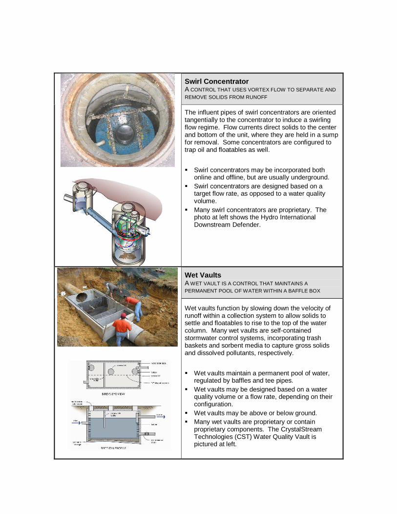
Swirl Concentrator A CONTROL THAT USES VORTEX FLOW TO SEPARATE AND
REMOVE SOLIDS FROM RUNOFF
The influent pipes of swirl concentrators are oriented tangentially to the concentrator to induce a swirling flow regime. Flow currents direct solids to the center and bottom of the unit, where they are held in a sump for removal. Some concentrators are configured to trap oil and floatables as well.
� Swirl concentrators may be incorporated both
online and offline, but are usually underground. � Swirl concentrators are designed based on a
target flow rate, as opposed to a water quality volume.
� Many swirl concentrators are proprietary. The photo at left shows the Hydro International Downstream Defender.
Wet Vaults A WET VAULT IS A CONTROL THAT MAINTAINS A PERMANENT POOL OF WATER WITHIN A BAFFLE BOX
Wet vaults function by slowing down the velocity of runoff within a collection system to allow solids to settle and floatables to rise to the top of the water column. Many wet vaults are self-contained stormwater control systems, incorporating trash baskets and sorbent media to capture gross solids and dissolved pollutants, respectively.
� Wet vaults maintain a permanent pool of water,
regulated by baffles and tee pipes. � Wet vaults may be designed based on a water
quality volume or a flow rate, depending on their configuration.
� Wet vaults may be above or below ground. � Many wet vaults are proprietary or contain
proprietary components. The CrystalStream Technologies (CST) Water Quality Vault is pictured at left.