example transport engineering guide (teg): tellabs...
TRANSCRIPT

BOTC-TEG-6900
Example Transport Engineering Guide (TEG): Tellabs 1000 Digital Loop Carrier (previously known as Tellabs AccessMAX and AFC UMC1000). Central Office applications.
Section Table of Contents Page
DS Data Sheet (weight, footprint, power, heat, timing, alarms/rm, DF blocks, CLEI) 2
1 Overview 3
2 Equipment requirements 4
3 Relay rack layouts 5
4 Mechanized Loop Test (MLT) methods 6
5 Internal aggregation 6
6 Intact DS3 transport
B) Tracer Lamp (TL) colors: TLs are used to identify near and far end cross
connect points in the DSX-3 environment. DSX-XA-BB-24R Cross Aisle and DSX4H
series DSX-3 panels (see section 4) have one TL LED for each position (24 per
panel). DSX4R series DSX-3 panels have two TL LEDs (front and back of panel) for
each position (32 per panel). The DSX-3 color standard is red for DS3 and yellow for
STS-1.
2
BOTC-TEG-2300
All ADC panels with TL capability are shipped with -48V red LEDs. If the panel
position usage is DS3 or unknown, the red LEDs should be left in place. If the panel
position usage is STS-1, the red LEDs should be replaced with yellow LEDs. These
ADC part numbers can be used to order -48V yellow LEDs (see section 11 for -24V
condition):
FLEDY: 1 yellow LED for DSX4H DSX-3 or DSX-XA-BB-24R Cross Aisle panel.
STS-KIT-Y: Kit of 24 yellow LEDs for DSX4H DSX-3 or DSX-XA-BB-24R Cross Aisle
panel.
FLED-A-YEL: 1 yellow LED for DSX4R DSX-3 panel.
FLED-A-KIT-YEL: Kit of 100 yellow LEDs for DSX4R DSX-3 panel.
In some cases, panels with yellow LEDs may need to be converted back to red (STS-1
termination changed to DS3). These ADC part numbers can be used to order -48V
red LEDs (see section 11 for -24V condition):
FLEDR: 1 red LED for DSX4H DSX-3 or DSX-XA-BB-24R Cross Aisle panel.
FLED-A-RED: 1 red LED for DSX4R DSX-3 panel.
7
7 System connection details (except VF/DS0) 7-10
8 System VF/DS0 connection and DF block layout/pair count/wiring color code 11-15
Issue Revisions Date
1 Original release of Bill Oakes Engineering Guideline for AFC UMC1000. August 6, 1997
20 Revise into Word format. August 1, 2007
Acronyms: American Wire Gauge (AWG), Battery Distribution Fuse Board (BDFB), Central Office (CO),
Competitive Local Exchange Carrier (CLEC), Digital Cross connect System-electronic (DCS), Digital Loop Carrier
(DLC), Digital System Cross connect-manual (DSX), Distributing Frame (DF), Enclosed Network Extension-
RT/CEV/Hut/Prem (ENE), Fiber Distribution Frame (FDF), Local Exchange Terminal (LET), Network Element
(NE), Receive (RX), Support Engineering Guide (SEG), Transmit (TX), Voice Frequency (VF).
Bill Oakes Telecom Consultants (BOTC)
[email protected], 831-476-0453
Copyright 1997. All rights reserved.
1

BOTC-TEG-6900
Data Sheet:
The preface section of all BOTC-TEGs is a data sheet that provides quick view information for weight, relay rack
footprint, peak (LIST 2)/nominal (LIST 1) power amperage, heat dissipation wattage, timing, alarms/remote
management, DF block and CLEI code requirements. The data shown is an ultimate condition (relay rack fully
loaded with equipment as designed in associated BOTC-TEG). Even though many relay rack deployments are
partially equipped, BOTC recommends basing initial space/engineering planning on ultimate data since existing
rack layouts typically grow to conclusion without follow-up involvement by planning personnel.
Category Requirement
Weight 400 pounds
Timing (BITS)2 or 4 BITS CC
outputs
Alarms 1 discrete
Remote
management
1 or 2 Ethernet
TL1
DF blocks 9 or 6
PWFYAL1CAA
SBMFF30B
Peak/LIST 2
amperage at
42.6V
32 amps
Eight 0210-0117/-0122 shelves at 4 amps each. See BOTC-SEG-0500 section
2 for calculation method.
Data sheet for CO Tellabs 1000 DLC relay rack
Footprint
Remarks
One relay rack: 120 pounds. One fuse panel: 10 pounds. Three heat
baffles: 15 pounds. Eight fully equipped 0210-0117/0122 shelves (32
pounds each): 256 pounds.
26" wide x 12"
deep
26" wide rack. 5" deep front guard box. 2" deep rear guard box.
CLEI codes (see
BOTC-SEG-0600
section 4)
Nominal/LIST 1
amperage at
52V
11.2 ampsEight 0210-0117/-0122 shelves at 1.4 amps each.
Heat
dissipation352 watts
Telect 0HPGMT05R fuse panel.
Tellabs 1000 0210-0117 or -0122 shelf
Eight 0210-0117/0122 shelves at 44 watts each.
Each Tellabs 1000 DLC system requires one set of primary and secondary
BITS Composite Clock (CC) outputs. One CC set for TR-57 (one eight shelf
system) racks. Two CC sets for GR-303 (two four shelf system) racks.
1 status point required on CO alarm system for Tellabs 1000 rack fuse
panel alarm
Nine 100 pair blocks for TR-57 (one eight shelf system) or six 100 pair
blocks for GR-303 (two four shelf systems). See BOTC-SEG-0300 section 2
or 8. If the DF is Conventional, blocks mount on vertical side.
Each Tellabs 1000 DLC system requires one Ethernet TL1 connection to
the CO remote management system. One Ethernet for TR-57 (one eight
shelf system) racks. Two Ethernet for GR-303 (two four shelf system)
2
BOTC-TEG-6900
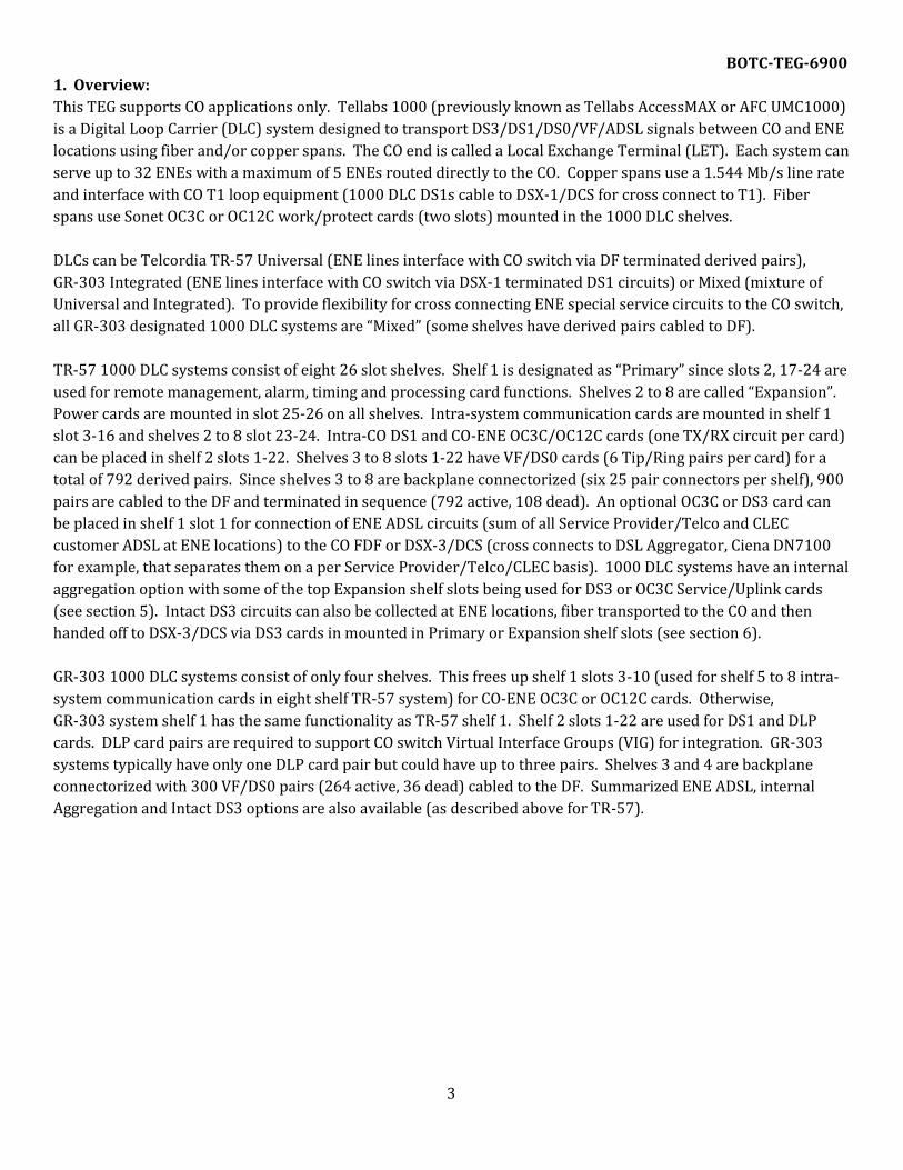
1. Overview:
This TEG supports CO applications only. Tellabs 1000 (previously known as Tellabs AccessMAX or AFC UMC1000)
is a Digital Loop Carrier (DLC) system designed to transport DS3/DS1/DS0/VF/ADSL signals between CO and ENE
locations using fiber and/or copper spans. The CO end is called a Local Exchange Terminal (LET). Each system can
serve up to 32 ENEs with a maximum of 5 ENEs routed directly to the CO. Copper spans use a 1.544 Mb/s line rate
and interface with CO T1 loop equipment (1000 DLC DS1s cable to DSX-1/DCS for cross connect to T1). Fiber
spans use Sonet OC3C or OC12C work/protect cards (two slots) mounted in the 1000 DLC shelves.
DLCs can be Telcordia TR-57 Universal (ENE lines interface with CO switch via DF terminated derived pairs),
GR-303 Integrated (ENE lines interface with CO switch via DSX-1 terminated DS1 circuits) or Mixed (mixture of
Universal and Integrated). To provide flexibility for cross connecting ENE special service circuits to the CO switch,
all GR-303 designated 1000 DLC systems are “Mixed” (some shelves have derived pairs cabled to DF).
TR-57 1000 DLC systems consist of eight 26 slot shelves. Shelf 1 is designated as “Primary” since slots 2, 17-24 are
used for remote management, alarm, timing and processing card functions. Shelves 2 to 8 are called “Expansion”.
Power cards are mounted in slot 25-26 on all shelves. Intra-system communication cards are mounted in shelf 1
slot 3-16 and shelves 2 to 8 slot 23-24. Intra-CO DS1 and CO-ENE OC3C/OC12C cards (one TX/RX circuit per card)
can be placed in shelf 2 slots 1-22. Shelves 3 to 8 slots 1-22 have VF/DS0 cards (6 Tip/Ring pairs per card) for a
total of 792 derived pairs. Since shelves 3 to 8 are backplane connectorized (six 25 pair connectors per shelf), 900
pairs are cabled to the DF and terminated in sequence (792 active, 108 dead). An optional OC3C or DS3 card can
be placed in shelf 1 slot 1 for connection of ENE ADSL circuits (sum of all Service Provider/Telco and CLEC
customer ADSL at ENE locations) to the CO FDF or DSX-3/DCS (cross connects to DSL Aggregator, Ciena DN7100
for example, that separates them on a per Service Provider/Telco/CLEC basis). 1000 DLC systems have an internal
aggregation option with some of the top Expansion shelf slots being used for DS3 or OC3C Service/Uplink cards
(see section 5). Intact DS3 circuits can also be collected at ENE locations, fiber transported to the CO and then
handed off to DSX-3/DCS via DS3 cards in mounted in Primary or Expansion shelf slots (see section 6).
GR-303 1000 DLC systems consist of only four shelves. This frees up shelf 1 slots 3-10 (used for shelf 5 to 8 intra-
system communication cards in eight shelf TR-57 system) for CO-ENE OC3C or OC12C cards. Otherwise,
GR-303 system shelf 1 has the same functionality as TR-57 shelf 1. Shelf 2 slots 1-22 are used for DS1 and DLP
cards. DLP card pairs are required to support CO switch Virtual Interface Groups (VIG) for integration. GR-303
systems typically have only one DLP card pair but could have up to three pairs. Shelves 3 and 4 are backplane
connectorized with 300 VF/DS0 pairs (264 active, 36 dead) cabled to the DF. Summarized ENE ADSL, internal
Aggregation and Intact DS3 options are also available (as described above for TR-57).
3

BOTC-TEG-6900
2. Equipment requirements:
This section provides part number and mounting/usage details for equipment in Tellabs 1000 DLC relay racks.
Layouts for TR-57 and GR-303 systems are shown in figure 3A and 3B. The racks can be factory or field assembled
(see BOTC-SEG-0600 section 9). Part A and B of this section are the factory TR-57 and GR-303 methods. Part C
and J are required for both methods (factory or field). Part D to H are the field method for TR-57 or GR-303.
A) Factory assembled rack with one 8 shelf TR-57 system: Tellabs part number 0220-0066 provides:
1 Newton 2196470033 or Telect 12300KW201 Unequal Flange rack (7’, 1.75 x 23 drilling, 5” front welded box).
1 Telect 0HPGMT05R fuse panel.
24 Telect 06100B-7.5 fuses (7.5 amp). 16 working and 8 spare.
16 Telect 102435-17 designation pins for 7.5 amp fuse.
1 Tellabs 0220-0067 Primary package (see part F).
5 Tellabs 0220-0068 Expansion packages (see part G).
3 Tellabs 0410-0291 heat baffles.
1 Set of intra-rack wiring (includes part A-step 2, B, C, E and H of section 7 System connections).
B) Factory assembled rack for two 4 shelf GR-303 systems: Tellabs part number 0220-0069 provides:
1 Newton 2196470033 or Telect 12300KW201 Unequal Flange rack (7’, 1.75 x 23 drilling, 5” front welded box).
1 Telect 0HPGMT05R fuse panel.
24 Telect 06100B-7.5 fuses (7.5 amp). 16 working and 8 spare.
16 Telect 102435-17 designation pins for 7.5 amp fuse.
2 Tellabs 0220-0067 Primary packages (see part F).
2 Tellabs 0220-0068 Expansion packages (see part G).
3 Tellabs 0410-0291 heat baffles.
1 Set of intra-rack wiring (includes part A-step 2, B, C, E and H of section 7 System connections).
C) Guard box (factory or field assembly): One 2” rear field mount guard box must be ordered as a separate item
so that the footprint depth is 12” (5” front, 2” rear). See BOTC-SEG-0600.
D) Relay rack (field assembly): One 7’ Unequal Flange rack with 1.75 x 23 drilling code and 5” front welded
guard box. See BOTC-SEG-0600.
E) Fuse panel (field assembly): One Telect 0HPGMT05R. 1.75” high. See BOTC-SEG-0500.
F) Primary package (field assembly): Provide one for TR-57 rack or two for GR-303 rack. Tellabs Primary
package part number 0220-0067 consists of: two 0210-0117 wire wrap shelves; one 0210-0122 connectorized
shelf; three 0215-0009 5” stand-off sets; two 0410-0052 MTU cables; two 0410-0003 EBF3 fibers; two 0410-0245
EBF3-BB fibers; one 0410-0241 SNMPI cable; one 0550-0007 Backup 1.0 ENG. 0210-0117 and -0122 shelves are
7” high, 12” deep, 19” wide (23” rack adapters included with shelf) with a flush set out (use 0215-0009 stand-offs).
G) Expansion package (field assembly): Provide five for TR-57 rack or two for GR-303 rack. Tellabs Expansion
package part number 0220-0068 consists of: one 0210-0122 connectorized shelf; one 0215-0009 5” stand-off set;
one 0410-0052 MTU cable; two 0410-0003 EBF3 fibers.
H) Heat baffle (field assembly): Provide three Tellabs 0410-0291 heat baffles for TR-57 or GR-303 rack. Baffle
is 1.75” high, 9.35” deep, 23” wide with a 3.84” front set out. Baffle required between even/odd numbered shelves
for routing warm air to rear aisle. Baffle space between even/odd shelves and open space between odd/even
shelves is used to route intra-system communication fibers.
J) Bulkhead panel (factory or field assembly): Provide one optional Tellabs 0410-0315 Bulkhead panel and
Westek coax assemblies (variable quantity) for DS3 card interface with CO overhead coax. See section 7 part N, Q
or R.
4

BOTC-TEG-6900
3. Relay rack layouts:
BV or 43 Fuse panel BV or 43 Fuse panelBU or 42 0410-0315 Bulkhead BU or 42 0410-0315 BulkheadBT or 41 BT or 41
BS or 40 BS or 40
BR or 39 BR or 39
BQ or 38 8 BQ or 38 4
BP or 37 Open space BP or 37 Open spaceBN or 36 BN or 36
BM or 35 BM or 35
BL or 34 BL or 34
BK or 33 7 BK or 33 3
BJ or 32 0410-0291 Heat baffle BJ or 32 0410-0291 Heat baffleBH or 31 BH or 31
BG or 30 BG or 30BF or 29 BF or 29
BE or 28 6 BE or 28 2
BD or 27 Open space BD or 27 Open spaceBC or 26 BC or 26
BB or 25 BB or 25
BA or 24 BA or 24
V or 23 5 V or 23 1
U or 22 0410-0291 Heat baffle U or 22 0410-0291 Heat baffle T or 21 T or 21
S or 20 S or 20
R or 19 R or 19
Q or 18 4 Q or 18 4
P or 17 Open space P or 17 Open space N or 16 N or 16
M or 15 M or 15
L or 14 L or 14
K or 13 3 K or 13 3
J or 12 0410-0291 Heat baffle J or 12 0410-0291 Heat baffle H or 11 H or 11
G or 10 G or 10
F or 9 F or 9
E or 8 2 E or 8 2
D or 7 Open space D or 7 Open space C or 6 C or 6
B or 5 B or 5
A or 4 A or 4
AA or 3 1 AA or 3 1
AB or 2 AB or 2
AC or 1 AC or 1
1.75 x 23 1.75 x 23
FIGURE 3A FIGURE 3B
0210-0122
Expansion shelf
0210-0117
Expansion shelf
0210-0117
Primary shelf
Layout for two 4 shelf GR-303 Mixed
systems (factory or field assembled).
Provide 2" x 2" vertical fiber protection
duct on left front upright down to shelf
1 level.
0210-0122
Expansion shelf
0210-0122
Expansion shelf
0210-0117
Expansion shelf
0210-0117
Primary shelf
0210-0122
Expansion shelf
0210-0122
Expansion shelf
0210-0122
Expansion shelf
0210-0122
Expansion shelf
Layout for one 8 shelf TR-57 Universal
system (factory or field assembled).
Provide 2" x 2" vertical fiber protection
duct on left front upright down to shelf
1 level.
0210-0117
Primary shelf
0210-0117
Expansion shelf
0210-0122
Expansion shelf
0210-0122
Expansion shelf
0210-0122
Expansion shelf
5

BOTC-TEG-6900
4. Mechanized Loop Test (MLT) methods:
A) Background: When customers report service problems, their line needs to be tested. In the late 1970s, the Bell
System started to deploy SD2P017-01 Loop Test Frame (LTF) remote testing equipment (also known as MLT-1).
In 1981, next generation SD2P076-01 Loop Test Systems (LTS) were introduced (also known as MLT-2). In 2001,
Tollgrade purchased the Lucent LTF/LTS product lines. Tollgrade also developed their own Digital Measurement
Node (DMN) version of this equipment for new testheads or replacement of old MLT-1 systems. Around 1980
most Service Providers/Telcos began to use CO-ENE Pair Gain (PG) systems (Lucent SLC-96 for example) for
transporting customer lines on multiplexed copper pairs. Since ENE lines connect to the CO switch via derived
(instead of direct local loop) pairs, SD97760-01 Pair Gain Test Controller (PGTC) shelves were added to act as the
PG-MLT interface since CO switch Number Test Trunks (NTT) could not be used. An industry standard 25 pair
mult runs from the PGTC to any CO PG systems (Lucent SLC, Nortel DMS-1, Alcatel Litespan, etc) that require this
ENE test line method. Copper based PG systems transport the test circuit on separate CO-ENE Metallic Test Pairs
(MTP). Fiber based PG systems usually insert the test circuit into their fiber overhead for CO-ENE transport.
B) Tellabs 1000 DLC methods: This system has the ability to “fool” the CO switch into thinking that TR-57 or GR-
303 derived pairs are actually direct local loop pairs. The Primary shelf 1 slot 22 OSI card acts as an MLT interface
with the CO switch and then inserts a test circuit onto it’s own CO-ENE overhead using the slot 21 DBP card. This
eliminates the need for a PGTC mult connection. Field experience with 1000 DLC GR-303 systems indicates that
switch MLT flowthrough functions somewhat differently than the TR-57 method. Even though a PGTC mult is still
not required for GR-303 systems, the testing must come through an MLT DF cross connect (see section 7 part G) to
a CO switch NTT circuit. TR-57 systems do not need this MLT DF cross connect unless future conversion to GR-303
is anticipated. When deploying new 1000 DLC TR-57 systems, BOTC recommends that engineering vendors
consult with Service Provider/Telco personnel about the MLT DF cross connect issue.
5. Internal aggregation:
A) Overview: Service Providers/Telcos and CLECs are trying their best to sell DSL service to customers. If those
customers are within range of a CO they will interface the network via local loop pairs terminating on the CO MDF
vertical side and cross connect to Digital Subscriber Line Access Multiplexer (DSLAM) equipment. If customers are
not within range of a CO, a DLC system is deployed at the nearest ENE so DSL service can be sold from that location.
Alcatel Litespan-2000/2012 DLC collects regular and DSL circuits at the ENE and groups them into separate fibers
for transport to the CO. Tellabs 1000 DLC groups regular and DSL circuits separately at the ENE but uses the same
ENE-CO transport fiber for both groups. 1000 DLC CO LET equipment then separates out the summarized group of
DSL circuits for OC3C or DS3 uplink (from shelf 1 slot 1 card position) to the CO FDF or DSX-3/DCS (cross connects
to DSL Aggregator, Ciena DN7100 for example, that separates them on a per Service Provider/Telco/CLEC basis).
To provide flexibility, Tellabs has developed an internal aggregation feature for the 1000 DLC system (if Service
Providers/Telcos decide not to use the external DSL Aggregator method).
B) Tellabs 1000 DLC engineering procedures: In the CO, one 1000 DLC system is selected as the Combination
(Combo) LET. Combo LET shelf 8 (if TR-57) or shelf 4 (if GR-303) is used to mount up to eleven Aggregation cards
(eight OC3C, three DS3). Four of the OC3C cards are used for a Service function. Fiber from the Service cards runs
to an FDF panel. Up to four other 1000 DLC LETs (called Subtending systems in this application) have fiber run
from a shelf 1, slot 1 OC3C card (summarized DSL from their ENEs). When these fiber circuits are cross connected,
the Combo LET combines all five DSL sets (four Subtending LETs and the Combo LET itself via intra-system fiber).
The Combo LET then divides DSL signals into Uplink groups (up to seven) on a per Service Provider/Telco/CLEC
basis. OC3C (up to four) or DS3 (up to three) cards are used to hand-off the Uplink groups via FDF or DSX-3/DCS
cross connect. Since internal Aggregation requires broadband capability, the two 0410-0003 EBF3 fibers used for
intra-system communication (see section 2G) must be replaced with 0410-0245 EBF3-BB. To provide flexibility,
Expansion shelves planned for internal Aggregation should still have all VF/DS0 pairs cabled to the DF.
6
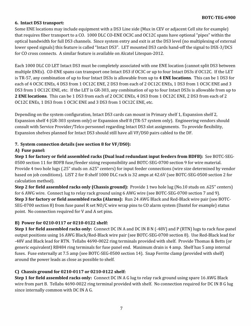
BOTC-TEG-6900 6. Intact DS3 transport:
Some ENE locations may include equipment with a DS3 Line side (Mux in CEV or adjacent Cell site for example)
that requires fiber transport to a CO. 1000 DLC CO-ENE OC3C and OC12C spans have optional “pipes” within the
optical bandwidth for full DS3 channels. Since system entry and exit is at the DS3 level (no multiplexing of external
lower speed signals) this feature is called “Intact DS3”. LET mounted DS3 cards hand-off the signal to DSX-3/DCS
for CO cross connects. A similar feature is available on Alcatel Litespan-2012.
Each 1000 DLC CO LET Intact DS3 must be completely associated with one ENE location (cannot split DS3 between
multiple ENEs). CO-ENE spans can transport one Intact DS3 if OC3C or up to four Intact DS3s if OC12C. If the LET
is TR-57, any combination of up to four Intact DS3s is allowable from up to 4 ENE locations. This can be 1 DS3 for
each of 4 OC3C ENEs, 4 DS3 from 1 OC12C ENE, 2 DS3 from each of 2 OC12C ENEs, 1 DS3 from 1 OC3C ENE and 3
DS3 from 1 OC12C ENE, etc. If the LET is GR-303, any combination of up to four Intact DS3s is allowable from up to
2 ENE locations. This can be 1 DS3 from each of 2 OC3C ENEs, 4 DS3 from 1 OC12C ENE, 2 DS3 from each of 2
OC12C ENEs, 1 DS3 from 1 OC3C ENE and 3 DS3 from 1 OC12C ENE, etc.
Depending on the system configuration, Intact DS3 cards can mount in Primary shelf 1, Expansion shelf 2,
Expansion shelf 4 (GR-303 system only) or Expansion shelf 8 (TR-57 system only). Engineering vendors should
consult with Service Provider/Telco personnel regarding Intact DS3 slot assignments. To provide flexibility,
Expansion shelves planned for Intact DS3 should still have all VF/DS0 pairs cabled to the DF.
7. System connection details (see section 8 for VF/DS0):
A) Fuse panel:
Step 1 for factory or field assembled racks (Dual load redundant input feeders from BDFB): See BOTC-SEG-
0500 section 11 for BDFB fuse/feeder sizing responsibility and BOTC-SEG-0700 section 9 for wire material.
Provide 4 two hole lugs (.25” studs on .625” centers) for input feeder connections (wire size determined by vendor
based on job conditions). LIST 2 for 8 shelf 1000 DLC rack is 32 amps at 42.6V (see BOTC-SEG-0500 section 2 for
calculation method).
Step 2 for field assembled racks only (Chassis ground): Provide 1 two hole lug (No.10 studs on .625” centers)
for 6 AWG wire. Connect lug to relay rack ground using 6 AWG wire (see BOTC-SEG-0700 section 7 and 9).
Step 3 for factory or field assembled racks (Alarms): Run 24 AWG Black and Red-Black wire pair (see BOTC-
SEG-0700 section 8) from fuse panel R set NO/C wire wrap pins to CO alarm system (Dantel for example) status
point. No connection required for V and A set pins.
B) Power for 0210-0117 or 0210-0122 shelf:
Step 1 for field assembled racks only: Connect DC IN A and DC IN B N (-48V) and P (RTN) lugs to rack fuse panel
output positions using 16 AWG Black/Red-Black wire pair (see BOTC-SEG-0700 section 8). Use Red-Black lead for
-48V and Black lead for RTN. Tellabs 4690-0022 ring terminals provided with shelf. Provide Thomas & Betts (or
generic equivalent) RB484 ring terminals for fuse panel end. Maximum drain is 4 amp. Shelf has 5 amp internal
fuses. Fuse externally at 7.5 amp (see BOTC-SEG-0500 section 14). Snap Ferrite clamp (provided with shelf)
around the power leads as close as possible to shelf.
C) Chassis ground for 0210-0117 or 0210-0122 shelf:
Step 1 for field assembled racks only: Connect DC IN A G lug to relay rack ground using spare 16 AWG Black
wire from part B. Tellabs 4690-0022 ring terminal provided with shelf. No connection required for DC IN B G lug
since internally common with DC IN A G.
7

BOTC-TEG-6900 D) Timing for 0210-0117 Primary shelf only:
Step 1 for factory or field assembled racks (Resistors and strap wire): Three 133 Ohm resistors (one is spare)
are provided with the 0220-0067 Primary package. On the rear side of 0210-0117 shelf slot 19, mount one resistor
across pins 3T-3R and one across pins 4T-4R. Provide a short length of 22 AWG Black wire (see BOTC-SEG-0700
section 8). Use the wire to add rear side straps between slot 19 pin 4R to slot 20 pin 4R, slot 19 pin 4T to slot 20
pin 4T, slot 19 pin 3R to slot 20 pin 3R, slot 19 pin 3T to slot 20 pin 3T.
Step 2 for factory or field assembled racks ( external timing cables): See BOTC-SEG-0100 section 9 for
methods. Run two single pair timing cables from shelf to CO BITS distribution equipment Composite Clock
outputs. Connect primary pair to shelf slot 20 pins 3T (LX lead), 3R (LY lead) and secondary pair to slot 20 pins 4T
(LX lead), 4R (LY lead). Do not ground cables at shelf end (no capacitive ground feature).
E) Timing for 0210-0117 or 0210-0122 Expansion shelf only:
Step 1 for field assembled racks only: This connection is only required when there is a possibility that cards on
a 0210-0117 or 0210-0122 Expansion shelf will provide DDS related service. Engineering vendors should consult
with Service Provider/Telco personnel. If future DDS related service is uncertain, BOTC recommends making this
connection on all Expansion shelves during the initial rack installation (may prevent having to do follow-up job at a
later date). See BOTC-SEG-0100 section 9 for methods. Provide two single pair timing cables for intra-system
connection from each Expansion shelf (rear side Alarm Contact Pinfield) to 0210-0117 Primary shelf (rear side
1T/1R pins for associated slot 3 to 16 intra-system communication cards). Expansion shelf pin details are A7 for
Primary LX lead, B7 for Primary LY, C3 for Secondary LX, D3 for Secondary LY and D6 for drain wire connection of
both cables (do not ground cables at Primary shelf end). Primary shelf details are slot 15/16, 13/14, 11/12, 9/10,
7/8, 5/6, 3/4 for Expansion shelf 2 to 8 Primary/Secondary timing respectively and pin 1T (LX lead), 1R (LY lead).
F) Remote management for 0210-0117 Primary shelf only:
Step 1 for factory or field assembled racks (wiring of stub cable): Primary package (section 2F) includes one
0410-0241 SNMPI stub cable that must be wired to the rear side pins of Primary 0210-0117 shelf slot 2. Wire stub
cable W-G lead to pin 5R, G-W lead to pin 5T, W-O lead to pin 2R, O-W lead to pin 2T. This establishes an Ethernet
10BASE-T circuit on the stub cable RJ45 connector (pin 1 is TX+, pin 2 TX-, pin 3 RX+, pin 6 RX-).
Step 2 for factory or field assembled racks (external remote management cable): Run electrical Ethernet
cable with straight pinning (see BOTC-SEG-0100 section 10) from shelf slot 2 stub cable RJ45 connector to CO
Remote management Ethernet hub equipment.
G) Mechanized Loop Test for 0210-0117 Primary shelf only:
Step 1 for factory or field assembled racks (external wiring to DF): See section 4B for requirements. Run one
24 AWG quad (see BOTC-SEG-0700 section 8) from Primary shelf rear side slot 22 pins (pin 1T for Tip lead, 1R for
Ring lead, 3T for Inhibit lead) to a DF block location as designated by Service Provider/Telco personnel. One lead
in the quad wire is spare. Terminate and stencil leads on one DF block pin column in Tip, Ring, Inhibit sequence.
H) Metallic Test mult for 0210-0117 or 0210-0122 Expansion shelf only:
Step 1 for field assembled racks only : Primary and Expansion packages (section 2F and 2G) include one 0410-
0052 MTU cable for an intra-system Metallic Test mult between shelves. Connect this cable from the MTU
P33/P34 plug on succeeding Expansion shelf to the MTU P31/P32 plug on preceding Primary or Expansion shelf.
8
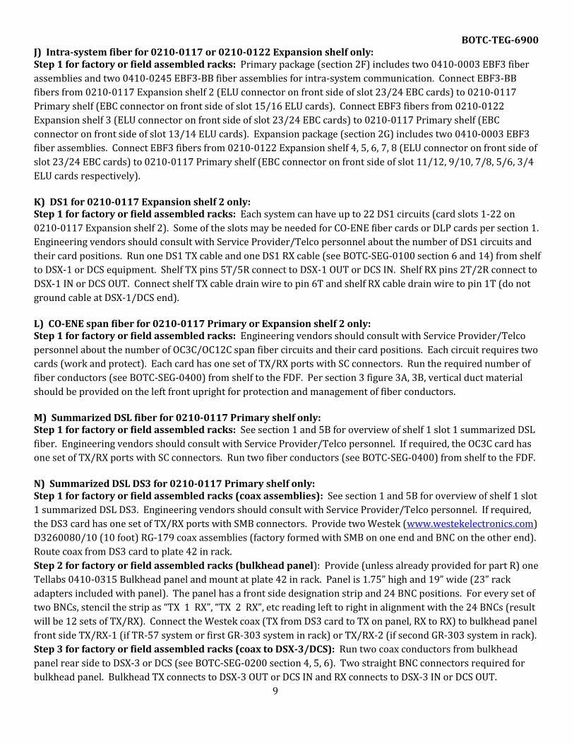
BOTC-TEG-6900 J) Intra-system fiber for 0210-0117 or 0210-0122 Expansion shelf only: Step 1 for factory or field assembled racks: Primary package (section 2F) includes two 0410-0003 EBF3 fiber
assemblies and two 0410-0245 EBF3-BB fiber assemblies for intra-system communication. Connect EBF3-BB
fibers from 0210-0117 Expansion shelf 2 (ELU connector on front side of slot 23/24 EBC cards) to 0210-0117
Primary shelf (EBC connector on front side of slot 15/16 ELU cards). Connect EBF3 fibers from 0210-0122
Expansion shelf 3 (ELU connector on front side of slot 23/24 EBC cards) to 0210-0117 Primary shelf (EBC
connector on front side of slot 13/14 ELU cards). Expansion package (section 2G) includes two 0410-0003 EBF3
fiber assemblies. Connect EBF3 fibers from 0210-0122 Expansion shelf 4, 5, 6, 7, 8 (ELU connector on front side of
slot 23/24 EBC cards) to 0210-0117 Primary shelf (EBC connector on front side of slot 11/12, 9/10, 7/8, 5/6, 3/4
ELU cards respectively).
K) DS1 for 0210-0117 Expansion shelf 2 only: Step 1 for factory or field assembled racks: Each system can have up to 22 DS1 circuits (card slots 1-22 on
0210-0117 Expansion shelf 2). Some of the slots may be needed for CO-ENE fiber cards or DLP cards per section 1.
Engineering vendors should consult with Service Provider/Telco personnel about the number of DS1 circuits and
their card positions. Run one DS1 TX cable and one DS1 RX cable (see BOTC-SEG-0100 section 6 and 14) from shelf
to DSX-1 or DCS equipment. Shelf TX pins 5T/5R connect to DSX-1 OUT or DCS IN. Shelf RX pins 2T/2R connect to
DSX-1 IN or DCS OUT. Connect shelf TX cable drain wire to pin 6T and shelf RX cable drain wire to pin 1T (do not
ground cable at DSX-1/DCS end).
L) CO-ENE span fiber for 0210-0117 Primary or Expansion shelf 2 only: Step 1 for factory or field assembled racks: Engineering vendors should consult with Service Provider/Telco
personnel about the number of OC3C/OC12C span fiber circuits and their card positions. Each circuit requires two
cards (work and protect). Each card has one set of TX/RX ports with SC connectors. Run the required number of
fiber conductors (see BOTC-SEG-0400) from shelf to the FDF. Per section 3 figure 3A, 3B, vertical duct material
should be provided on the left front upright for protection and management of fiber conductors.
M) Summarized DSL fiber for 0210-0117 Primary shelf only: Step 1 for factory or field assembled racks: See section 1 and 5B for overview of shelf 1 slot 1 summarized DSL
fiber. Engineering vendors should consult with Service Provider/Telco personnel. If required, the OC3C card has
one set of TX/RX ports with SC connectors. Run two fiber conductors (see BOTC-SEG-0400) from shelf to the FDF.
N) Summarized DSL DS3 for 0210-0117 Primary shelf only: Step 1 for factory or field assembled racks (coax assemblies): See section 1 and 5B for overview of shelf 1 slot
1 summarized DSL DS3. Engineering vendors should consult with Service Provider/Telco personnel. If required,
the DS3 card has one set of TX/RX ports with SMB connectors. Provide two Westek (www.westekelectronics.com)
D3260080/10 (10 foot) RG-179 coax assemblies (factory formed with SMB on one end and BNC on the other end).
Route coax from DS3 card to plate 42 in rack.
Step 2 for factory or field assembled racks (bulkhead panel): Provide (unless already provided for part R) one
Tellabs 0410-0315 Bulkhead panel and mount at plate 42 in rack. Panel is 1.75” high and 19” wide (23” rack
adapters included with panel). The panel has a front side designation strip and 24 BNC positions. For every set of
two BNCs, stencil the strip as “TX 1 RX”, “TX 2 RX”, etc reading left to right in alignment with the 24 BNCs (result
will be 12 sets of TX/RX). Connect the Westek coax (TX from DS3 card to TX on panel, RX to RX) to bulkhead panel
front side TX/RX-1 (if TR-57 system or first GR-303 system in rack) or TX/RX-2 (if second GR-303 system in rack).
Step 3 for factory or field assembled racks (coax to DSX-3/DCS): Run two coax conductors from bulkhead
panel rear side to DSX-3 or DCS (see BOTC-SEG-0200 section 4, 5, 6). Two straight BNC connectors required for
bulkhead panel. Bulkhead TX connects to DSX-3 OUT or DCS IN and RX connects to DSX-3 IN or DCS OUT.
9

BOTC-TEG-6900
P) Aggregation fiber for 0210-0122 Expansion shelf 4 or 8 only: Step 1 for factory or field assembled racks: See 5B for background on Expansion shelf 4 (GR-303 system) and
Expansion shelf 8 (TR-57 system) Aggregation fiber. Engineering vendors should consult with Service
Provider/Telco personnel about the number of OC3C circuits and their card positions. If required, each card has
one set of TX/RX ports with SC connectors. Run the required number of fiber conductors (see BOTC-SEG-0400)
from shelf to the FDF.
Q) Aggregation DS3 for 0210-0122 Expansion shelf 4 or 8 only: Step 1 for factory or field assembled racks (coax assemblies): See section 5B for background on Expansion
shelf 4 (GR-303 system) and Expansion shelf 8 (TR-57 system) Aggregation DS3. Engineering vendors should
consult with Service Provider/Telco personnel about the number of DS3 circuits and their card positions. If
required, each DS3 card has one set of TX/RX ports with SMB connectors. For each DS3 card, provide two Westek
(www.westekelectronics.com) D3260080/19 (19 inch if shelf 8 for TR-57 system or shelf 4 for second GR-303
system in rack) or D3260080/10 (10 foot if shelf 4 for first GR-303 system in rack) RG-179 coax assemblies
(factory formed with SMB on one end and BNC on the other end). Route coax from DS3 card to plate 42 in rack.
Step 2 for factory or field assembled racks (bulkhead panel): Provide (unless already provided for part R) one
Tellabs 0410-0315 Bulkhead panel and mount at plate 42 in rack. Panel is 1.75” high and 19” wide (23” rack
adapters included with panel). The panel has a front side designation strip and 24 BNC positions. For every set of
two BNCs, stencil the strip as “TX 1 RX”, “TX 2 RX”, etc reading left to right in alignment with the 24 BNCs (result
will be 12 sets of TX/RX). Connect the Westek coax (TX from DS3 card to TX on panel, RX to RX) to bulkhead panel
front side TX/RX-1, TX/RX-2, TX/RX-3 (if TR-57 system or first GR-303 system in rack) or TX/RX-4, TX/RX-5,
TX/RX-6 (if second GR-303 system in rack).
Step 3 for factory or field assembled racks (coax to DSX-3/DCS): Run two coax conductors for each TX/RX
circuit from bulkhead panel rear side to DSX-3 or DCS (see BOTC-SEG-0200 section 4, 5, 6). Two straight BNC
connectors required per TX/RX circuit for bulkhead panel. Bulkhead TX connects to DSX-3 OUT or DCS IN and RX
connects to DSX-3 IN or DCS OUT.
R) Intact DS3 for 0210-0117 or 0210-0122 shelf: Step 1 for factory or field assembled racks (coax assemblies): See section 6 for background on Intact DS3.
Engineering vendors should consult with Service Provider/Telco personnel about the number of DS3 circuits and
their card positions. If required, each DS3 card has one set of TX/RX ports with SMB connectors. For each DS3
card, provide two Westek (www.westekelectronics.com) D3260080/19 (19 inch) or D3260080/10 (10 foot) RG-
179 coax assemblies (factory formed with SMB on one end and BNC on the other end). Use 10 foot assemblies if
DS3 card in Primary shelf 1, Expansion shelf 2 or Expansion shelf 4 (first GR-303 system in rack). Use 19 inch
assemblies if Expansion shelf 8 (TR-57 system) or Expansion shelf 4 (second GR-303 system in rack). Route coax
from DS3 card to plate 42 in rack.
Step 2 for factory or field assembled racks (bulkhead panel): Provide (unless already provided for part N or
Q) one Tellabs 0410-0315 Bulkhead panel and mount at plate 42 in rack. Panel is 1.75” high and 19” wide (23”
rack adapters included with panel). The panel has a front side designation strip and 24 BNC positions. For every
set of two BNCs, stencil the strip as “TX 1 RX”, “TX 2 RX”, etc reading left to right in alignment with the 24 BNCs
(result will be 12 sets of TX/RX). Connect the Westek coax (TX from DS3 card to TX on panel, RX to RX) to
bulkhead panel front side TX/RX-7, TX/RX-8, TX/RX-9, TX/RX-10, TX/RX-11, TX/RX-12, TX/RX-6, TX/RX-5.
Step 3 for factory or field assembled racks (coax to DSX-3/DCS): Run two coax conductors for each TX/RX
circuit from bulkhead panel rear side to DSX-3 or DCS (see BOTC-SEG-0200 section 4, 5, 6). Two straight BNC
connectors required per TX/RX circuit for bulkhead panel. Bulkhead TX connects to DSX-3 OUT or DCS IN and RX
connects to DSX-3 IN or DCS OUT.
10

BOTC-TEG-6900
8. System VF/DS0 connection and DF block layout/pair count/wiring color code:
A) Cables: Each 0210-0122 Expansion shelf backplane has six 25 pair connectors that are factory designated JA-1,
JA-2, JB-1, JB-2, JC-1 and JC-2. As viewed from rear side of rack, JA-1, JC-1, JC-2 are designed to exit left and JA-2, JB-
1, JB-2 are designed to exit right. Two 25 pair (for JA-1, JA-2) and two 50 pair (has two 25 pair breakout legs for
JB-1/JB-2 or JC-1/JC-2) cables should be used for each shelf. Two 75 pair cables (one per side) cannot be used
since the binder groups would not terminate in sequence on the DF (would split between separate blocks). The
cables should be 1107A type (see BOTC-SEG-0100 section 8 and 14) with female connectors on the shelf end. At
the shelf end, each cable must have a 3 foot long insulated drain wire that will be connected to relay rack ground by
installation. BOTC recommends these factory formed cables (see BOTC-SEG-0100 section 7 for manufacturer
contacts). –XXX indicates footage.
25 pair: Cablcon T0860-0001-XXX, Conway CCI-337-XXX, Great Lakes 97232-XXX or CSI CA4XXXX101TSD1.
50 pair: Cablcon T0860-0010-XXX, Conway CCI-C338-XXX, Great Lakes 97233-XXX or CSI CA4XXXX3C4TSD1.
B) Pair count: 1000 DLC VF/DS0 pairs should be DF stenciled using a CO Switch Digital Loop Equipment (DLE)
method called Carrier Controller Indentifier/Carrier Controller Port (CCI/CCPT). This method designates each pair
by it’s shelf number, shelf slot number and slot pair number. For example, Expansion shelf 3, slot 17, pair 4 would
be designated 3-17-4. See figure 8A, 8B and 8C.
C) DF block layout: TR-57 systems require nine 100 pair blocks. GR-303 systems require three 100 pair blocks.
See BOTC-SEG-0300 section 2 or 8 for block part numbers. If the DF is Conventional, blocks mount on the vertical
side. Each shelf has 150 pairs that are terminated in sequence (132 active, 18 dead). Figure 8B and 8C detail the
layout.
11

Slot
Lead
Conn
Pin
Colo
r
Slot
Lead
Conn
Pin
Colo
r
Slot
Lead
Conn
Pin
Colo
r
T-1 26 W-BL T-2 26 W-BL T-3 26 W-BL
R-1 1 BL-W R-2 1 BL-W R-3 1 BL-W
T-2 27 W-O T-3 27 W-O T-4 27 W-O
R-2 2 O-W R-3 2 O-W R-4 2 O-W
T-3 28 W-G T-4 28 W-G T-5 28 W-G
R-3 3 G-W R-4 3 G-W R-5 3 G-W
T-4 29 W-BR T-5 29 W-BR T-6 29 W-BR
R-4 4 BR-W R-5 4 BR-W R-6 4 BR-W
T-5 30 W-S T-6 30 W-S T-1 30 W-S
R-5 5 S-W R-6 5 S-W R-1 5 S-W
T-6 31 R-BL T-1 31 R-BL T-2 31 R-BL
R-6 6 BL-R R-1 6 BL-R R-2 6 BL-R
T-1 32 R-O T-2 32 R-O T-3 32 R-O
R-1 7 O-R R-2 7 O-R R-3 7 O-R
T-2 33 R-G T-3 33 R-G T-4 33 R-G
R-2 8 G-R R-3 8 G-R R-4 8 G-R
T-3 34 R-BR T-4 34 R-BR T-5 34 R-BR
R-3 9 BR-R R-4 9 BR-R R-5 9 BR-R
T-4 35 R-S T-5 35 R-S T-6 35 R-S
R-4 10 S-R R-5 10 S-R R-6 10 S-R
T-5 36 BK-BL T-6 36 BK-BL T-1 36 BK-BL
R-5 11 BL-BK R-6 11 BL-BK R-1 11 BL-BK
T-6 37 BK-O T-1 37 BK-O T-2 37 BK-O
R-6 12 O-BK R-1 12 O-BK R-2 12 O-BK
T-1 38 BK-G T-2 38 BK-G T-3 38 BK-G
R-1 13 G-BK R-2 13 G-BK R-3 13 G-BK
T-2 39 BK-BR T-3 39 BK-BR T-4 39 BK-BR
R-2 14 BR-BK R-3 14 BR-BK R-4 14 BR-BK
T-3 40 BK-S T-4 40 BK-S T-5 40 BK-S
R-3 15 S-BK R-4 15 S-BK R-5 15 S-BK
T-4 41 Y-BL T-5 41 Y-BL T-6 41 Y-BL
R-4 16 BL-Y R-5 16 BL-Y R-6 16 BL-Y
T-5 42 Y-O T-6 42 Y-O T-1 42 Y-O
R-5 17 O-Y R-6 17 O-Y R-1 17 O-Y
T-6 43 Y-G T-1 43 Y-G T-2 43 Y-G
R-6 18 G-Y R-1 18 G-Y R-2 18 G-Y
T-1 44 Y-BR T-2 44 Y-BR T-3 44 Y-BR
R-1 19 BR-Y R-2 19 BR-Y R-3 19 BR-Y
T-2 45 Y-S T-3 45 Y-S T-4 45 Y-S
R-2 20 S-Y R-3 20 S-Y R-4 20 S-Y
T-3 46 V-BL T-4 46 V-BL T-5 46 V-BL
R-3 21 BL-V R-4 21 BL-V R-5 21 BL-V
T-4 47 V-O T-5 47 V-O T-6 47 V-O
R-4 22 O-V R-5 22 O-V R-6 22 O-V
T-5 48 V-G T-6 48 V-G T-1 48 V-G
R-5 23 G-V R-6 23 G-V R-1 23 G-V
T-6 49 V-BR T-1 49 V-BR T-2 49 V-BR
R-6 24 BR-V R-1 24 BR-V R-2 24 BR-V
T-1 50 V-S T-2 50 V-S T-3 50 V-S
R-1 25 S-V R-2 25 S-V R-3 25 S-V
JB-1
BOTC-TEG-6900
Page 12
FIGURE 8A
(continued on page 13)
0210-0122 Expansion shelf
VF/DS0 lead designations
and color code. Lead
designations are stenciled
on the DF block using Switch
DLE method. For example,
Expansion shelf 3, slot 11,
pair 4 would be 3-11-4.
9
10
11
12
13
6
7
8
9
JA-25
3
1
2
4
JA-1
5

Slot
Lead
Conn
Pin
Colo
r
Slot
Lead
Conn
Pin
Colo
r
Slot
Lead
Conn
Pin
Colo
r
T-4 26 W-BL T-5 26 W-BL T-6 26 W-BL
R-4 1 BL-W R-5 1 BL-W R-6 1 BL-W
T-5 27 W-O T-6 27 W-O T-1 27 W-O
R-5 2 O-W R-6 2 O-W R-1 2 O-W
T-6 28 W-G T-1 28 W-G T-2 28 W-G
R-6 3 G-W R-1 3 G-W R-2 3 G-W
T-1 29 W-BR T-2 29 W-BR T-3 29 W-BR
R-1 4 BR-W R-2 4 BR-W R-3 4 BR-W
T-2 30 W-S T-3 30 W-S T-4 30 W-S
R-2 5 S-W R-3 5 S-W R-4 5 S-W
T-3 31 R-BL T-4 31 R-BL T-5 31 R-BL
R-3 6 BL-R R-4 6 BL-R R-5 6 BL-R
T-4 32 R-O T-5 32 R-O T-6 32 R-O
R-4 7 O-R R-5 7 O-R R-6 7 O-R
T-5 33 R-G T-6 33 R-G T 33 R-G
R-5 8 G-R R-6 8 G-R R 8 G-R
T-6 34 R-BR T-1 34 R-BR T 34 R-BR
R-6 9 BR-R R-1 9 BR-R R 9 BR-R
T-1 35 R-S T-2 35 R-S T 35 R-S
R-1 10 S-R R-2 10 S-R R 10 S-R
T-2 36 BK-BL T-3 36 BK-BL T 36 BK-BL
R-2 11 BL-BK R-3 11 BL-BK R 11 BL-BK
T-3 37 BK-O T-4 37 BK-O T 37 BK-O
R-3 12 O-BK R-4 12 O-BK R 12 O-BK
T-4 38 BK-G T-5 38 BK-G T 38 BK-G
R-4 13 G-BK R-5 13 G-BK R 13 G-BK
T-5 39 BK-BR T-6 39 BK-BR T 39 BK-BR
R-5 14 BR-BK R-6 14 BR-BK R 14 BR-BK
T-6 40 BK-S T-1 40 BK-S T 40 BK-S
R-6 15 S-BK R-1 15 S-BK R 15 S-BK
T-1 41 Y-BL T-2 41 Y-BL T 41 Y-BL
R-1 16 BL-Y R-2 16 BL-Y R 16 BL-Y
T-2 42 Y-O T-3 42 Y-O T 42 Y-O
R-2 17 O-Y R-3 17 O-Y R 17 O-Y
T-3 43 Y-G T-4 43 Y-G T 43 Y-G
R-3 18 G-Y R-4 18 G-Y R 18 G-Y
T-4 44 Y-BR T-5 44 Y-BR T 44 Y-BR
R-4 19 BR-Y R-5 19 BR-Y R 19 BR-Y
T-5 45 Y-S T-6 45 Y-S T 45 Y-S
R-5 20 S-Y R-6 20 S-Y R 20 S-Y
T-6 46 V-BL T-1 46 V-BL T 46 V-BL
R-6 21 BL-V R-1 21 BL-V R 21 BL-V
T-1 47 V-O T-2 47 V-O T 47 V-O
R-1 22 O-V R-2 22 O-V R 22 O-V
T-2 48 V-G T-3 48 V-G T 48 V-G
R-2 23 G-V R-3 23 G-V R 23 G-V
T-3 49 V-BR T-4 49 V-BR T 49 V-BR
R-3 24 BR-V R-4 24 BR-V R 24 BR-V
T-4 50 V-S T-5 50 V-S T 50 V-S
R-4 25 S-V R-5 25 S-V R 25 S-V
JB-213
14
15
16
17
JC-117
18
19
20
21
21
22
DEAD
PAI
RS
BOTC-TEG-6900
Page 13
FIGURE 8A
(continued from page 12)
0210-0122 Expansion shelf
VF/DS0 lead designations
and color code. Lead
designations are stenciled
on the DF block using Switch
DLE method. For example,
Expansion shelf 3, slot 15,
pair 4 would be 3-15-4.
JC-2

BOTC-TEG-6900
T R T R T R T R T R T R T R T R T R T R T R T R
FIGURE 8B
Conventional block layout for Tellabs 1000 DLC 0210-0122 Expansion shelves.
1st, 2nd, 3rd blocks shown for TR-57 or GR-303 Expansion shelf 3, 4.
4th through 9th blocks for TR-57 Expansion shelf 5 to 8 not shown.
View is from block's front (jumper) side.
1st Conventional block 2nd Conventional block 3rd Conventional block
3-5-1
3-5-5
3-6-3
3-7-1
3-7-5
3-8-3
3-9-1
3-9-5
3-10-3
3-11-1
3-11-5
3-12-3
3-6-5
3-7-3
3-8-1
3-8-5
3-15-2
3-15-6
3-1-1
3-1-5
3-2-3
3-3-1
3-3-5
3-4-3
3-9-6
3-10-4
3-17-1
3-1-2
3-1-6
3-2-4
3-3-2
3-3-6
3-4-4
3-5-2
3-5-6
3-6-4
3-13-1
3-13-5
3-14-3
3-15-1
3-15-5
3-16-3 3-16-4
3-17-2
3-1-3
3-2-1
3-2-5
3-3-3
3-4-1
3-4-5
3-11-2
3-11-6
3-12-4
3-13-2
3-13-6
3-14-4
3-7-2
3-7-6
3-8-4
3-9-2
3-17-3
3-13-3
3-14-1
3-14-5
3-15-3
3-16-1
3-1-4
3-2-2
3-2-6
3-3-4
3-4-2
3-4-6
3-5-4
3-6-2
3-6-6
3-16-5
3-9-3
3-10-1
3-10-5
3-11-3
3-12-1
3-12-5
3-5-3
3-6-1
3-17-4
3-17-5 3-17-6
3-19-1 3-19-2
3-20-3 3-20-4
3-11-4
3-12-2
3-12-6
3-13-4
3-14-2
3-14-6
3-7-4
3-8-2
3-8-6
3-9-4
3-10-2
3-10-6
3-Dead 3-Dead
4-3-3 4-3-4
4-6-1
3-18-1 3-18-2
3-18-3 3-18-4 3-18-5 3-18-6
3-15-4
3-16-2
3-16-6
3-20-5 3-20-6
3-21-1 3-21-2 3-21-3 3-21-4
3-19-3 3-19-4
3-19-5 3-19-6 3-20-1 3-20-2
3-Dead 3-Dead 3-Dead 3-Dead
3-Dead 3-Dead 3-Dead 3-Dead
3-21-5 3-21-6 3-22-1 3-22-2
3-22-3 3-22-4 3-22-5 3-22-6
4-1-1 4-1-2
4-1-3 4-1-4 4-1-5 4-1-6
3-Dead 3-Dead 3-Dead 3-Dead
3-Dead 3-Dead 3-Dead 3-Dead
4-3-5 4-3-6
4-4-1 4-4-2 4-4-3 4-4-4
4-2-1 4-2-2 4-2-3 4-2-4
4-2-5 4-2-6 4-3-1 4-3-2
4-6-2 4-6-3 4-6-4
4-6-5 4-6-6 4-7-1 4-7-2
4-4-5 4-4-6 4-5-1 4-5-2
4-5-3 4-5-4 4-5-5 4-5-6
4-9-5 4-9-6
4-10-1 4-10-2 4-10-3 4-10-4
4-8-5 4-8-6 4-9-1 4-9-2
4-9-3 4-9-4
4-10-5 4-10-6
4-12-1 4-12-2
4-7-3 4-7-4 4-7-5 4-7-6
4-8-1 4-8-2 4-8-3 4-8-4
4-12-3 4-12-4
4-12-5 4-12-6 4-13-1 4-13-2
4-11-1 4-11-2
4-11-3 4-11-4 4-11-5 4-11-6
4-14-5 4-14-6 4-15-1 4-15-2
4-15-3 4-15-4 4-15-5 4-15-6
4-13-3 4-13-4 4-13-5 4-13-6
4-14-1 4-14-2 4-14-3 4-14-4
4-17-3 4-17-4 4-17-5 4-17-6
4-18-1 4-18-2 4-18-3 4-18-4
4-16-1 4-16-2 4-16-3 4-16-4
4-16-5 4-16-6 4-17-1 4-17-2
4-20-1 4-20-2 4-20-3 4-20-4
4-20-5 4-20-6 4-21-1 4-21-2
4-18-5 4-18-6 4-19-1 4-19-2
4-19-3 4-19-4 4-19-5 4-19-6
4-22-5 4-22-6 4-Dead 4-Dead
4-Dead 4-Dead 4-Dead 4-Dead
4-21-3 4-21-4 4-21-5 4-21-6
4-22-1 4-22-2 4-22-3 4-22-4
4-Dead 4-Dead 4-Dead 4-Dead
4-Dead 4-Dead 4-Dead 4-Dead
4-Dead 4-Dead 4-Dead 4-Dead
14

BOTC-TEG-6900
T
R
T
R
T
R
T
R
T
R
T
R
T
R
T
R
T
R
T
R
T
R
T
R
FIGURE 8C
3-13
-43-
9-3
3-5-
23-
1-1
3-10
-53-
6-4
3-2-
3
3-6-
13-
1-6
3-14
-43-
10-3
3-6-
23-
2-1
3-6-
33-
2-2
3-14
-23-
10-1
3-5-
63-
1-5
3-13
-53-
9-4
3-5-
33-
1-2
3-13
-6
3-14
-13-
9-6
3-9-
53-
5-4
3-1-
3
3-5-
53-
1-4
3-15
-43-
11-3
3-7-
23-
3-1
3-15
-13-
10-6
3-14
-53-
10-4
3-14
-33-
10-2
3-14
-6
3-7-
13-
2-6
3-15
-33-
11-2
3-6-
53-
2-4
3-15
-23-
6-6
3-11
-13-
2-5
3-16
-13-
11-6
3-7-
53-
3-4
3-16
-23-
12-1
3-7-
63-
3-5
3-15
-53-
11-4
3-7-
33-
3-2
3-15
-63-
11-5
3-7-
43-
3-3
3-16
-53-
12-4
3-8-
33-
4-2
3-16
-63-
12-5
3-8-
43-
4-3
3-16
-33-
12-2
3-8-
13-
3-6
3-16
-43-
12-3
3-8-
23-
4-1
3-17
-33-
13-2
3-9-
13-
4-6
3-17
-43-
13-3
3-9-
23-
5-1
3-17
-13-
12-6
3-8-
53-
4-4
3-17
-23-
13-1
3-8-
63-
4-5
1st Cosmic block
3-17
-5
3-17
-6
3-18
-1
3-18
-2
3-18
-3
3-18
-4
3-18
-5
3-18
-6
3-19
-1
3-19
-2
3-19
-3
3-19
-4
3-19
-5
3-19
-6
3-20
-1
3-20
-2
3-20
-3
3-20
-4
3-20
-5
3-20
-6
3-21
-1
3-21
-2
3-21
-3
3-21
-4
3-21
-5
3-21
-6
3-22
-1
3-22
-2
3-22
-3
3-22
-4
3-22
-5
3-22
-6
3-D
ead
3-D
ead
3-D
ead
3-D
ead
3-D
ead
3-D
ead
3-D
ead
3-D
ead
3-D
ead
3-D
ead
3-D
ead
3-D
ead
3-D
ead
3-D
ead
3-D
ead
3-D
ead
3-D
ead
3-D
ead
4-1-
1
4-1-
2
4-1-
3
4-1-
4
4-1-
5
4-1-
6
4-2-
1
4-2-
2
4-2-
3
4-2-
4
4-2-
5
4-2-
6
4-3-
1
4-3-
2
4-3-
3
4-3-
4
4-3-
5
4-3-
6
4-4-
1
4-4-
2
4-4-
3
4-4-
4
4-4-
5
4-4-
6
4-5-
1
4-5-
2
4-5-
3
4-5-
4
4-5-
5
4-5-
6
4-6-
1
4-6-
2
4-6-
3
4-6-
4
4-6-
5
4-6-
6
4-7-
1
4-7-
2
4-7-
3
4-7-
4
4-7-
5
4-7-
6
4-8-
1
4-8-
2
4-8-
3
4-8-
4
4-8-
5
4-8-
6
4-9-
1
4-9-
2
2nd Cosmic block
4-9-
3
4-9-
4
4-9-
5
4-9-
6
4-10
-1
4-10
-2
4-10
-3
4-10
-4
4-10
-5
4-10
-6
4-11
-1
4-11
-2
4-11
-3
4-11
-4
4-11
-5
4-11
-6
4-12
-1
4-12
-2
4-12
-3
4-12
-4
4-12
-5
4-12
-6
4-13
-1
4-13
-2
4-13
-3
4-13
-4
4-13
-5
4-13
-6
4-14
-1
4-14
-2
4-14
-3
4-14
-4
4-14
-5
4-14
-6
4-15
-1
4-15
-2
4-15
-3
4-15
-4
4-15
-5
4-15
-6
4-16
-1
4-16
-2
4-17
-5
4-17
-6
4-18
-1
4-18
-2
4-18
-3
4-18
-4
4-18
-5
4-18
-6
4-19
-1
4-D
ead
4-D
ead
4-D
ead
4-D
ead
4-21
-4
4-21
-5
4-16
-3
4-16
-4
4-16
-5
4-16
-6
4-17
-1
4-17
-2
4-17
-3
4-17
-4
4-20
-3
4-20
-4
4-20
-5
4-20
-6
4-21
-1
4-21
-2
4-21
-3
4-19
-2
4-19
-3
4-19
-4
4-19
-5
4-19
-6
4-20
-1
4-20
-2
Cosmic block layout for Tellabs 1000 DLC 0210-0122 Expansion shelves.
1st, 2nd, 3rd blocks shown for TR-57 or GR-303 Expansion shelf 3, 4.
4th through 9th blocks for TR-57 Expansion shelf 5 to 8 not shown.
View is from block's front (jumper) side.
4-D
ead
4-D
ead
3rd Cosmic block
4-D
ead
4-D
ead
4-D
ead
4-D
ead
4-D
ead
4-D
ead
4-D
ead
4-D
ead
4-D
ead
4-21
-6
4-22
-1
4-22
-2
4-22
-3
4-22
-4
4-22
-5
4-22
-6
4-D
ead
4-D
ead
4-D
ead
15