example 6 - deck design including type 10 mash rail
TRANSCRIPT

EXAMPLE 6 - DECK DESIGN INCLUDING COLLISION ON A TYPE 10 MASH BARRIER
===============================================================================================
1
APPENDIX A
EXAMPLE 6 - DECK DESIGN INCLUDING TYPE 10 MASH RAIL COLLISION
EXAMPLE 6.1 - DECK DESIGNGENERAL INFORMATION
Based on AASHTO LRFD Bridge Design Specifications 9.6.1, there are 3 methods of deck analysis:
1. Approximate Elastic Method, or "Equivalent Strip" Method (AASHTO 4.6.2.1)
2. Refined Methods (AASHTO 4.6.3.2)
3. Empirical Design Method (AASHTO 9.7.2)
MATERIAL AND SECTION PROPERTIES
Structure Type
Girder Spacing, maximum SGdr= 11.0 ft
Number of girders NGdr= 4 ea
Overall Deck width Wdeck= 43.0 ft
Deck slab thickness tdeck= 8 in
Overhang thickness (average) tOH= 9.67 in
Concrete top cover cTop= 2.0 in AASHTO T 5.10.1-1 & BDM 5.4.3
Concrete bottom cover cBot= 1.0 in AASHTO T 5.10.1-1
Wearing surface tWS= 3.0 in
Concrete strength f'c= 4.5 ksi (Concrete Class D or G compressive strength)
Reinforcement strength fy= 60.0 ksi (Minimum yield strength of grade 60 steel)
Concrete density Wc= 0.150 kcf
Deck overlay density WWS= 0.147 kcf BDM 3.4.2
Allowance for future utilities Wutil= 0.005 ksf BDM 3.4.3
Resistance factors φSTR = 0.9 (strength limit state)
φEE = 1.0 (extreme event limit state)
Correction factor for source aggregate K1= 1
Modulus of elasticity of reinforcement Es= 29000.0 ksi AASHTO 5.4.3.2
Modulus of elasticity of concrete Ec= 4435.3 ksi AASHTO 5.4.2.4
Modular ratio n=Es/Ec= 6.54
Girder Type
Girder web thickness web= 4.0 in
Girder top flange width flange= 48.0 in
This design example uses the Approximate Elastic Method (Equivalent Strip Method), in which the deck is divided into
transverse strips, assumed to be supported on rigid supports at the center of the girders.
CIP Concrete Deck
Box Girder
�� � 120,000����′��.��
===============================================================================================
CDOT Bridge Design Manual April 2021

EXAMPLE 6 - DECK DESIGN INCLUDING COLLISION ON A TYPE 10 MASH BARRIER
===============================================================================================
2
Barrier Type
CY of concrete for barrier section AB= 0.06 CY/ft
Barrier Weight Wbarrier= 0.461 kip/ft
(Refer to CDOT bridge Worksheet B-606-10MASH for more details)
UNFACTORED DEAD LOADS
+Moment in terms of wl2
0.08
-Moment in terms of wl2
0.10
Wdeck= 8.00 in /12 * 0.15 kcf = 0.1 klf
WWS= 3.00 in /12 * 0.147 kcf = 0.037 klf
Positive Moment
+Mdeck= 0.100 klf * (11.00 ft)^2 * 0.08 = 0.968 k-ft/ft
+MWS= 0.037 klf * (11.00 ft)^2 * 0.08 = 0.355 k-ft/ft
Negative Moment
-Mdeck= 0.100 klf * (11.00 ft)^2 * 0.10 = 1.21 k-ft/ft
-MWS= 0.037 klf * (11.00 ft)^2 * 0.10 = 0.444 k-ft/ft
UNFACTORED LIVE LOADS
Deck superstructure type b AASHTO T4.6.2.2.1-1
Design section = At the face of the supporting component 24.00 in AASHTO 4.6.2.1.6
Girder spacing, S= 11.0 ft
Maximum Live Loads per unit width:
Positive Moment from LL +MLL= 7.46 kip-ft/ft AASHTO T. A4-1
Negative Moment from LL -MLL= 4.52 kip-ft/ft AASHTO T. A4-1
FACTORED DESIGN LOADS
Mu = η [γDCMDC + γDWMDW + m γLL(MLL+ IM)]
η = 1.0 load modifier
γ - load factors specified in AASHTO T.3.4.1-1, T.3.4.1-2
m - multiple presence factor, included in values from AASHTO T. A4-1
IM - dynamic load allowance, included in values from AASHTO T. A4-1
γDC_max γDW_max γLL +MLL -MLL
1.25 1.5 1.75 14.80 -10.09
1 1 1 8.78 -6.17
Note - it is conservative to use minimum load factors for positive values of M 100 and M200 and negative values of M150.
Controlling positive factored moment +Mu = 14.80 kip-ft/ft
Controlling negative factored moment -Mu = -10.09 kip-ft/ft
Based on Table 3-22c, Continuous Beams Moment and Shear Coefficients - Equal Spans, Equally Loaded, in terms of wl2, +M
=0.080 and -M = 0.100 and will be used for this design
Live load moment can be determined by using AASHTO LRFD Bridge Design Specifications Appendix A4 T.A4-1. This table
lists positive and negative moments per unit width of the deck with various girder spacings and various distances from the
design section to the centerline of girders. This table is based on the equivalent strip method and interpolation is allowed when
needed.
Load Combination
Design MomentsLoad Factors
Type 10MASH
Concrete decks must be investigated for strength, service and extreme limit states. Fatigue and fracture limit states do not
need to be investigated (AASHTO 9.5).
Strength I
Service I
===============================================================================================
CDOT Bridge Design Manual April 2021

EXAMPLE 6 - DECK DESIGN INCLUDING COLLISION ON A TYPE 10 MASH BARRIER
===============================================================================================
3
DECK SLAB STRENGTH DESIGN
Width of the design section b = 12.0 in.
Resistance factor for tension-controlled section φSTR = 0.9 AASHTO 5.5.4.2
Positive Moment Capacity (bottom reinforcement)
Try Bar size # 5
Bar spacing s = 6.0 in.
Bar diameter db = 0.625 in.
Bar area Ab = 0.31 in.2
Area of steel per design strip
AS = b (Ab / s) = 12.0 in. * 0.310 in. / 6.0 in. = 0.62 in.2
Effective depth of section
dS = tDeck - cBot - 1/2 db = 8.0 in. - 1.0 in. - 0.625 in. / 2 = 6.69 in.
Depth of equivalent stress block
0.62 in. * 29000.0 ksi / (0.85 * 1.0 ksi * 12 in.) = 0.81 in.
Factored flexural resistance
= 0.90 * 0.62 in. * 60.0 ksi * (6.69 in. - 0.81 in. / 2) / 12 in./ft. = 17.53 kip-ft.
17.53 > 14.80 OK
Negative Moment Capacity (top reinforcement)
Try Bar size # 5
Bar spacing s = 5.0 in.
Bar Diameter db = 0.625 in.
Bar Area Ab = 0.31 in.2
Area of steel per 1.00 ft. design strip
AS = B (Ab / s) = 12 in. * 0.310 in. / 5.00 in. = 0.74 in.2
Effective depth of section
dS = tDeck - cTop - 1/2 db = 8.0 in. - 2.0 in. - 0.625 in. / 2 = 5.69 in.
Depth of equivalent stress block
0.74 in * 60.0 ksi / (0.85 * 4.5 ksi * 12 in.) = 0.97 in.
Factored flexural resistance
= 0.90 * 0.74in. * 60.0 ksi * (5.69 in. - 0.97 in. / 2) / 12 in./ft. = 17.41 kip-ft.
17.41 > 10.09 OK
Minimum Reinforcement AASHTO 5.6.3.3
• 1.33 times the positive factored ultimate moment
• Cracking moment
Cracking moment AASHTO 5.6.3.3-1
Design of deck reinforcement, including flexural resistance, limits of reinforcement, and control of cracking is based on
AASHTO LRFD Bridge Design Specifications 5.7.3 (typical rectangular beam design). The following design method can be
used for normal weight concrete with specified compressive strengths up to 15.0 ksi. Refer to Section 9, Deck and Deck
Systems, of this BDM for information about acceptable deck reinforcement sizes and spacing.
Unless otherwise specified, the amount of prestressed and non-prestressed tensile reinforcement shall be adequate to develop
a factored flexural resistance, Mr = φMn, at least equal to the lesser of:
� � ����0.85���� �
+��� � ����� �� − �2 �
�ℎ!"# + ��� > +�%:
� � �'��0.85���� �
−��� � ��'�� �' − �2 �
�ℎ!"# − ��� > −�%:
2
2
2
��) � *� *�) + *���+, -� − �.��-�
-��− 1
2
2
2
===============================================================================================
CDOT Bridge Design Manual April 2021

EXAMPLE 6 - DECK DESIGN INCLUDING COLLISION ON A TYPE 10 MASH BARRIER
===============================================================================================
4
Where: AASHTO 5.6.3.3
Flexural cracking variability factor γ1 = 1.6 (non-segmental brg.)
Ratio of specified min. yield strength to ultimate tensile strength γ3 = 0.67 (A615 steel)
Concrete density modification factor λ = 1.0 AASHTO 5.4.2.8
Modulus of rupture 0.509 ksi AASHTO 5.4.2.6
Section modulus of design section 12.0in. * (8.0 in.) / 6 = 128 in.3
Check Positive Moment reinforcement
1.33 (+Mu) = 1.33 * 14.80 kip-ft. = 19.68 kip-ft.
Mcr = 0.67 * 1.60 * 0.51 ksi * 128.0 in. / 12 in./ft. = 5.82 kip-ft.
17.53 > 5.82 OK
Check Negative Moment reinforcement
1.33 (-Mu) = 1.33 * 10.09 kip-ft. = 13.42 kip-ft.
Mcr = 0.67 * 1.60 * 0.51 ksi * 128.0 in. / 12 in./ft. = 5.82 kip-ft.
17.41 > 5.82 OK
CONTROL OF CRACKING AT SERVICE LIMIT STATE
AASHTO 5.6.7-1
In which: γe = 1.00
bs -
fss - calculated tensile stress in mild steel reinforcement at the service limit state ( ≤ 0.60 fy ksi)
dc -
Check Cracking at the Bottom of Deck (spacing of Positive Moment reinforcement):
dc = cBot + 1/2 db = 1.00 in. + 0.625 in. / 2 = 1.31 in.
1 + 1.31 in. / [0.7 (8.0 in. - 1.31 in.)] = 1.28
Tension reinforcement ratio 0.62 in. / (12 in. * 6.69 in.) = 0.008
0.271
0.910
8.78 kip-ft. * 12in./ft. / (0.62 in. * 0.91 * 6.69 in.) = 27.95 ksi
700 * 1.00 / (1.28 * 27.95 ksi) - 2 * 1.31in. = 16.94 in.
Spacing of positive moment reinforcement used in the design = 6.00 in.
6.00 < 16.94 OK
- exposure factor (1.0 for Class 1 and 0.75 for Class 2) (assume waterproofing membrane
is used)
ratio of flexural strain at the extreme tension face to the strain at the centroid of the reinforcement
layer nearest the tension face
thickness of concrete cover measured from extreme tension fiber to center of the flexural
reinforcement located closest thereto. For calculation purposes, d c need not be taken greater than 2
in. plus the bar radius
When simplified by removing all values applicable to prestressed and noncomposite sections, this equation becomes the
following:
Cracking is controlled by the spacing of mild steel reinforcement in the layer closest to the tension face, which shall satisfy the
following (need not be less than 5.00 in.):
��) � *�*�)-�
�) � 0.240 ���1 �
-� � �ℎ�
6 � �34,�5�
6 �
�ℎ!"# + ��� ≥ 789
�ℎ!"# − ��� ≥ 789
3
2
3
: ≤ 700*,='�''
− 2��
=� � 1 + �>0.7(34,�5 − �>) �
A � �����
�
# � 29A + 9A �1 − 9A �B � 1 − #/3 �
�'' � +�%_',)FG�,��B��
�
:HIJ � 700*,=����
− 2�> �
�ℎ!"# :K�"89L M:!� ≤ :HIJ:
2
2
===============================================================================================
CDOT Bridge Design Manual April 2021

EXAMPLE 6 - DECK DESIGN INCLUDING COLLISION ON A TYPE 10 MASH BARRIER
===============================================================================================
5
Check Cracking at Top of Deck (spacing of Negative Moment reinforcement):
dc = cTop + 1/2 db = 2.0 in. + 0.625 in. / 2 = 2.31 in.
1+ 2.31 in. / [0.7 * (8.0 in. - 2.31 in.)] = 1.58
Tension reinforcement ratio 0.74 in. / (12 in. * 5.69 in.) = 0.011
Modular ratio n = ES / EC = 29000 ksi / 4435 ksi = 6.54
0.313
0.896
6.17 kip-ft. * 12in./ft. / (0.74 in. * 0.90 * 5.69 in.) = 19.55 ksi
700 * 1.00 / (1.58 * 19.55 ksi) - 2 * 2.31 in. = 18.03 in.
Spacing of negative moment reinforcement used in the design = 5.00 in.
5.00 < 18.03 OK
LONGITUDINAL REINFORCEMENT
AASHTO 5.10.6-1
AASHTO 5.10.6-2
As,min = 1.3 * 12.0 in.* 8.0 in. / [2 (12.0 in. + 8.0 in.) 60.0 ksi] = 0.052 in.2/ft.
As,min = 0.11 in.2/ft. - controls
Top reinforcement try # 4 @ 6.00 in on center: AS = 0.40 in.2/ft.
OK
Effective span length 11.0 ft. - 48.0in. / 12in./ft. = 7 ft.
AASHTO 9.7.2.3
Amount of reinforcement required in secondary direction in the bottom of the slab
83% Use - 67% AASHTO 9.7.3.2
Area of primary reinforcement for positive moment = 0.62 in.2/ft.
Required area of bottom longitudinal steel: AS_Req = 67% * 0.62 in./ft.= 0.42 in.2/ft.
Bottom reinforcement try # 5 @ 8.00 in. on center: AS = 0.465 in.2/ft.
OK
OK
DECK SECTION SUMMARY
Deck thickness 8.00 in.
Top Transverse Reinforcement # 5 @ 5.00 in.
Bottom Transverse Reinforcement # 5 @ 6.00 in.
Top Longitudinal Reinforcement # 4 @ 6.00 in.
Bottom Longitudinal Reinforcement # 5 @ 8.00 in.
Minimum reinforcement is required in all directions to accommodate shrinkage and temperature changes near the surface of
the slab. Longitudinal reinforcement on each face shall meet the following:
Per Section 9.6 of the CDOT BDM, the minimum longitudinal reinforcing steel in the top of the concrete bridge deck shall be #4
@ 6.00 in. Longitudinal reinforcement in the bottom of the deck slab can be distributed as a percentage of the primary
reinforcement for positive moment.
A � �����
�
=' � 1 + �>0.7(34,�5 − �>) �
# � 29A + 9A �1 − 9A �B � 1 − #/3 �
�'' � −�%_',)FG�,��B��
�
:HIJ � 700*,=����
− 2�> �
�ℎ!"# :K�"89L M:!� ≤ :HIJ:
2
2
�� ≥ 1.3� 34,�52(� + 34,�5)��
0.11 ≤ �� ≤ 0.60
�ℎ!"# �� ≥ �� HG�
�ℎ!"# �� ≥ �� HG�
220-1 ≤ 67%
�ℎ!"# �� ≥ ��_O,P
- � -Q.) − L8R�!R S8�3ℎ
2
220-1 �
===============================================================================================
CDOT Bridge Design Manual April 2021

EXAMPLE 6 - DECK DESIGN INCLUDING COLLISION ON A TYPE 10 MASH BARRIER
===============================================================================================
6
EXAMPLE 6.2 - TYPE 10 MASH STRENGTH DESIGN
GENERAL INFORMATION
Overall barrier height HB = 43.0 in.
Concrete cover c = 2.0 in.
Resistance factors φEE = 1 (Extreme Event) AASHTO 1.3.2.1
φS = 0.8 (A325 bolts in shear) AASHTO 6.5.4.2
φT = 0.8 (A325 bolts in tension) AASHTO 6.5.4.2
Test level TL-4 AASHTO T.A13.2-1
Transverse design force Ft = 80.0 kips See table below
Impact force distribution Lt = 5.0 ft. See table below
CONCRETE PARAPET
Height HW = 13.4375 in.
Width at base d = 18.0 in.
Concrete Compressive Strength f'c = 4.5 ksi
Reinforcing Steel fy = 75.0 ksi
RAIL POST
Type W6x20
Steel grade
Post spacing L = 10 ft. (max)
Effective height HR = 32.5 in.
Area of post APost = 5.87 in.2
Web depth D = 5.47 in.
Web thickness tW = 0.26 in.
Flange thickness tF = 0.37 in.
Flange width bf= 6.02
Depth of W beam db= 6.2
Fy (post) = 50 ksi AISC Table 1-1
Zx-x (post) = 14.9 in.3
Mn=Mp=FyZ (F7-1 AISC Manual) Mpost= 62.08 kip-ft
RAIL TUBES AISC Table 1-12
Type
Steel grade
Area of one tube ATube = 5.59 in.2
Number of tubes nTubes = 2 ea.
Fy (tube) = 50.0 ksi
Z (tube) = 11.2 in.3
Mn=Mp=FyZ (F7-1 AISC Manual) Mp= 93.33 kip-ft
BASE PLATE
Width of base plate Wb = 12.0 in.
Thickness of base plate tb = 0.6875 in.
Distance to bolts dbo = 10.0 in.
Bolt diameter Ø = 0.875 in.
Min tensile strength Fub = 120.0 ksi
Number of bolts nb = 2
CDOT Bridge Rail Type 10MASH consists of a concrete parapet and a metal rail. The resistance to transverse vehicular impact
loads shall be determined as specified in AASHTO LRFD Bridge Design Specifications A13.3.3. End impact is not considered.
See CDOT Worksheet B-606-10MASH for barrier details.
ASTM A-572, Grade 50
HSS 6x6x1/4
ASTM A-1085
===============================================================================================
CDOT Bridge Design Manual April 2021

EXAMPLE 6 - DECK DESIGN INCLUDING COLLISION ON A TYPE 10 MASH BARRIER
===============================================================================================
7
CONCRETE PARAPET CAPACITY
Back face horizontal reinforcement Size = # 3 Bar Diameter = 0.375 in.
Number of bars = 2 Bar Area = 0.11 in2
Stirrup Dia. = 0.375 in.
Design strip, b = 13.0 in.
Area of steel per design strip AS = Bar Area * NO. of bars = 0.22 in.2/ft.
Effective depth of section dS = d - c - Stirrup Dia. - 1/2 Bar Dia. = 15.44 in.
Depth of equivalent stress block
0.22 in. * 75.0 ksi / (0.85 * 4.50 ksi * 13.0 in.) = 0.332 in.
Flexural resistance
1.0 * 0.22 in. * 75.0 ksi * (15.44 in. - 0.33 in. / 2) / 12 in./ft. = 21.00 kip-ft.
Stirrup Size = # 3 Bar Diameter = 0.375 in.
Stirrup spacing = 6.00 in. Bar Area = 0.11 in2
Area of steel per design strip AS = Bar Area * b / Stirrup spacing = 0.22 in.2/ft.
Effective depth of section dS = d - c - 1/2 Stirrup Dia. = 15.81 in.
Depth of equivalent stress block 0.36 in.
Flexural moment resistance 21.50 kip-ft./ft.
2. Determine M C : flexural resistance of cantilevered parapet about an axis parallel to the longitudinal
axis of the bridge. Flexural moment resistance is based on the vertical reinforcement in the barrier.
1. Determine M W : flexural resistance of the parapet about its vertical axis. Positive and negative
moment strength must be evaluated but will be equal based on barrier longitudinal reinforcement.
� � ����0.85���� �
�T � �UU���� �� − �2 �
� � ����0.85���� �
�� � �UU���� �� − �2 �
===============================================================================================
CDOT Bridge Design Manual April 2021

EXAMPLE 6 - DECK DESIGN INCLUDING COLLISION ON A TYPE 10 MASH BARRIER
===============================================================================================
8
Critical length of yield line failure pattern 6.37 ft.
There is no additional resistance at the top of the parapet in addition to MW , Mb = 0 kip-ft.
3. Determine R W (nominal railing resistance to transverse load) within a wall segment.
244.67 kip AASHTO A13.3.1-1
4. Calculate maximum post capacity P P .
a. Plastic moment capacity of the post
Yielding of post Mpost= 62.08 kip-ft
CG of impact force above curb HR - HW 19.06 in
Maximum shear force at base of the post, Pp to cause post failure
Mpost / (HR - HW) Pp1= 39.08 kip
b. Weld connection strength
Thickness of the weld tweld= 0.313 in
Effective thickness 0.77*tweld tweff= 0.22 in
Calculate fillet weld strength as a line (Design of Welded Structures by Blodgett)
SW = 19.32 in3
Strength of the weld FEXX = 70.00 ksi
Maximum weld moment Mweld = 67.63 kip-ft (0.6 * FEXX * SW)
Maximum shear force at base Pp2= 42.58 kip
c. Bolt shear strength
Shear resistance AASHTO 6.13.2.7-2
Rn = 0.45 * (pi * 7/8 in ^2)/4 * 120.0 ksi * 2 Pp3= 64.94 kip
d. Concrete breakout shear strength
Spacing of bolts bspa = 9.00 in ACI 318 17.7.2
Since the spacing of the anchors is less than 3 times the bolt distance db, the bolts must be treated as a group
Area resisting breakout AVC = 585 in2
(9.0 in + 3 * 10.0 in) * 1.5 * 10.0 in
Maximum area = nb * 4.5 dbo2
900 in2
AVCO = 450 in2
There is no eccentricity in shear loading and so modification factor for eccentricity ψec,V = 1.0 ACI 318 17.7.2.3
Edge distances (along the curb) > 1.5 x bolt distance and so modification factor for edge distance ψed,V = 1.0 ACI 318 17.7.2.4
Analysis indicates no cracking at service loads and so modification factor for concrete ψc,V = 1.4 ACI 318 17.7.2.5
Anchor embedment hef = 10.75 in
1.5 * dbo = 15.00 in
1.181 ACI 318 17.7.2.6
Basic shear strength is minimum of
Vb1 = 21.05 kip Vb2 = 19.09 kip
V> � VW2 + VW
2�
+ 8XT �Y + �T�>
�1
ZT � 22V> − VW
8�Y + 8�T + �>V>�
XT�
-T �(2*b*d + .⬚
\
� )*tweff
Z� � 0.45�Y]%Y '̂
_�Y � �`��`�a
b,�,`b,.,`b�,`bc,`_Y
bc,` � 1.5�Yℎ,d
1
_Y � 7 e,�
�.��1 0I �′�
1 (�Ya).f _Y� � 90I �′�1 (�Ya).f
===============================================================================================
CDOT Bridge Design Manual April 2021

EXAMPLE 6 - DECK DESIGN INCLUDING COLLISION ON A TYPE 10 MASH BARRIER
===============================================================================================
9
Load bearing length in shear le = 7 in (Min of hef and 8φ)
λa = 1.0 for normal weight concrete
Basic shear strength Vb = 19.09 kip
Shear strength Pp4= 41.05 kip
e. Bolt tensile strength (Ignore self weight)
Bolt tensile strength futa = 120.0 ksi Bolt outside diameter da = 0.895 in
φ= 0.75 Number of threads/in. nt = 9 in
Ase = 0.486 in2
Nsa = 43.75 kip
Tensile strength of 2 bolts = Ns = 87.50 kip
Equating tension and compression, depth of compression c = N s / (0.85 * f'c * Wb) c = 1.91 in
Moment lever arm = 7" - c/2 6.05 in
Moment capacity based on bolt tensile capacity Mbolt = 44.09 kip-ft
Mbolt / (HR - HW) Pp5= 27.76 kip
Minimum strength of post in shear PP = 27.76 kip
4. Calculate collision tensile force in deck T and collision moment M CT.
Impact at Midspan (3 spans) (Other odd spans didn't control and so not included)
Number of spans N= 3
Yielding of all rails Mp= 93.33 kip-ft
Impact force distribution Lt = 5.00 ft
post spacing L= 10.00 ft
AASHTO A13.3.2-1
=(16 * 93.33 kip-ft + 0) / (2 * 3 ft * 10.00 ft - 5.00 ft)
RR= 67.53 kip
=(67.53 kip +244.67 kip) = 312.1985 kip AASHTO A13.3.3-1
Therefore Use RW= 12.47 kip (80.00 kip - 67.53 kip ) 80.00 kip
AASHTO A13.3.3-2
=(67.53 kip * 32.50 in. +12.47 kip * 13.44 in.) / 80.00 kip
Y= 29.53 in
Tmid = 1.45 kip/ft
MCTmid = 1.62 kip-ft/ft
Impact at Post (2 spans) (Other even spans didn't control and so not included)
Number of spans N= 2
Impact force distribution Lt = 5.00 ft
post spacing L= 10.00 ft
Designing deck overhang for strength > strength of rails and curb is conservative. Therefore, design only for maximum MASH
Ft loads. Assume the rails fail during impact and curb resists the remaining load.
The resistance of each component of a combination bridge rail shall be determined as specified in Article A13.3.1 and A13.3.2
of the AASHTO code. The flexural strength of the rail shall be determined over one and two spans. The resistance of the
combination parapet and rail shall be taken as the lesser of the resistances determined for the two failure modes.
ZO � 16�+ + (^ − 1)(^ + 1)h+V2^V − VW
Zi � ZO + Zj
ki � ZOXO + ZjXjZi
Single span Zi �
l '̂I � l�',,m�%WI �', � n4 �I − 0.9743
9W �
o � ZjV> + 2Xj
�>p � o ∗ Xj
===============================================================================================
CDOT Bridge Design Manual April 2021

EXAMPLE 6 - DECK DESIGN INCLUDING COLLISION ON A TYPE 10 MASH BARRIER
===============================================================================================
10
AASHTO A13.3.2-2
=(16 * 93.33 kip-ft + 2^2 * 27.76 * 10.00/ (2 * 2 * 10.00 ft - 5.00 ft)
R'R= 74.39 kip
=(244.67 kip * 13.44 in. -27.76 kip * 32.50 in.) / 13.44 in AASHTO A13.3.3-5
R'W= 177.54 kip
= 27.76 kip + 74.39 kip + 177.54 kip 279.69 kip AASHTO A13.3.3-3
80 kip Ignore R'W and use reduced R'R = 52.24 kip (80.00 kip - 27.76 kip )
AASHTO A13.3.3-4
=(27.76 kip * 32.50 in. +52.24 kip * 32.50 in. + 0.00 kip * 13.44 in. ) / 80.00 kip
Y= 32.5 in
Tpost = 7.26 kip/ft
MCTpost = 19.66 kip-ft/ft
Use greater of the two failure modes \ Mct = 19.66 kip-ft/ft T = 7.26 kip/ft
SUMMARY
Impact at post controls the design as the transfer width is narrower than the impact between posts
Controlling Axial Load Per Unit Length of the Deck TAxial = 7.26 kip/ft.
Deck Overhang Moment Mct = 19.66 kip-ft./ft.
Z′O � 16�+ + ^�h+V2^V − VW
Zi � h+ + Z′O + Z′j
ki � h+XO + Z′OXO + Z′jXjZi
Z′j � ZjXj − h+XOXj
Use Zi �
o � h+Y + �Y + 2Xj
�>p � o ∗ ki
===============================================================================================
CDOT Bridge Design Manual April 2021

EXAMPLE 6 - DECK DESIGN INCLUDING COLLISION ON A TYPE 10 MASH BARRIER
======================================================================================
11
EXAMPLE 6.3 - BARRIER TYPE 7 STRENGTH DESIGNGENERAL INFORMATION
Overall barrier height HB = 35.00 in.
Concrete strength f'c = 4.50 ksi (Concrete Class D compressive strength)
Reinforcement strength fy = 60.00 ksi (Specified minimum yield strength of grade 60 steel)
Concrete cover c = 2.00 in.
Resistance factor φ = 1.00 (Extreme Event) AASHTO 1.3.2.1
Test level TL-4 AASHTO T A13.2-1
Transverse design force Ft = 54.00 kips
Impact force distribution Lt = 3.50 ft.
Barrier Dimensions
Section1 Section2 Section3
Section top width 10.50 13.00 18.00 in.
Section bottom width 13.00 18.00 18.00 in.
Section height 24.00 7.00 4.00 in.
Center of gravity from back face XC.G. = 6.84 in.
BARRIER FLEXURAL CAPACITY
Front face vertical reinforcement: # 4 @ 8.00 in Bar Diameter = 0.50 in.
Bar Area = 0.20 in.2
AS
(in.2)
h(avg)
(in.)
dS
(in.)
b
(in.)k= .85f'Cb
a=ASfy/k
(in.)
φMn
(kip-ft.)
MC
(kip-ft./ft.)Section 1 0.30 11.75 9.50 12.00 45.90 0.39 13.96 9.57
Section 2 0.30 15.50 13.25 12.00 45.90 0.39 19.58 3.92
Section 3 0.30 18.00 15.75 12.00 45.90 0.39 23.33 2.67
Barrier MC = 16.15 kip-ft./ft.
AS - area of steel per design strip
h(avg) - average section width
dS - effective depth of design section
b - width of design strip
a - depth of equivalent stress block
The CDOT Bridge Rail Type 7 design follows the AASHTO LRFD Bridge Design Specifications A13.3.1 design
procedure for concrete railings, using strength design for reinforced concrete. Although the Type 7 is not an
accepted bridge rail for new bridges (retired), the design methodology is similar to what would be done for the new
Type 9 Bridge Rail. The following calculations show case of impact within barrier segment, assuming that barrier will
be extended past the limits of the bridge. For cases concerning impact at end of the barrier, refer to AASHTO
Appendix A13.
1. Determine M C : flexural resistance of cantilevered parapet about an axis parallel to the longitudinal axis of the
bridge. Flexural moment resistance is based on the vertical reinforcement in the barrier.
Barrier Type 7
��� � ����� �� − �2 �> � t ��� · -!"38v9X!8Lℎ3
�
/Xw
======================================================================================
CDOT Bridge Design Manual April 2021
EXAMPLE 6 - DECK DESIGN INCLUDING COLLISION ON A TYPE 10 MASH BARRIER
======================================================================================
12
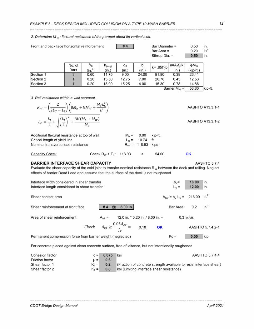
2. Determine M W : flexural resistance of the parapet about its vertical axis.
Front and back face horizontal reinforcement # 4 Bar Diameter = 0.50 in.
Bar Area = 0.20 in2
Stirrup Dia. = 0.50 in.
No. of
Bars
AS
(in.2)
h(avg)
(in.)
dS
(in.)
b
(in.)k= .85f'Cb
a=ASfy/k
(in.)
φMW
(kip-ft.)Section 1 3 0.60 11.75 9.00 24.00 91.80 0.39 26.41
Section 2 1 0.20 15.50 12.75 7.00 26.78 0.45 12.53
Section 3 1 0.20 18.00 15.25 4.00 15.30 0.78 14.86
Barrier MW = 53.80 kip-ft.
3. Rail resistance within a wall segment.
AASHTO A13.3.1-1
AASHTO A13.3.1-2
Additional flexural resistance at top of wall Mb = 0.00 kip-ft.
Critical length of yield line LC = 10.74 ft.
Nominal transverse load resistance RW = 118.93 kips
Capacity Check Check RW > Ft : 118.93 > 54.00 OK
BARRIER INTERFACE SHEAR CAPACITY AASHTO 5.7.4
Interface width considered in shear transfer bV= 18.00 in.
Interface length considered in shear transfer LV = 12.00 in.
Shear contact area ACV = bV LV = 216.00 in.2
Shear reinforcement at front face # 4 @ 8.00 in. Bar Area = 0.2 in.2
Area of shear reinforcement AVF = 12.0 in. * 0.20 in. / 8.00 in. = 0.3 in.2/ft.
0.18 OK AASHTO 5.7.4.2-1
Permanent compression force from barrier weight (neglected) Pc = 0.00 kip
For concrete placed against clean concrete surface, free of laitance, but not intentionally roughened
Cohesion factor c = 0.075 ksi AASHTO 5.7.4.4
Friction factor μ = 0.6
Shear factor 1 K1 = 0.2 (Fraction of concrete strength available to resist interface shear)
Shear factor 2 K2 = 0.8 ksi (Limiting interface shear resistance)
Evaluate the shear capacity of the cold joint to transfer nominal resistance RW between the deck and railing. Neglect
effects of barrier Dead Load and assume that the surface of the deck is not roughened.
ZT � 22V> − VW
8�Y + 8�T + �>V>�
X
V> � VW2 + VW
2�
+ 8X �Y + �T�>
1
�ℎ!"# �Fd ≥ 0.05��F��
�
======================================================================================
CDOT Bridge Design Manual April 2021

EXAMPLE 6 - DECK DESIGN INCLUDING COLLISION ON A TYPE 10 MASH BARRIER
======================================================================================
13
194.4 kip AASHTO 5.7.4.3
Vn = min 172.8 kip
27.00 kip
Resistance factor φ = 1.00 (Extreme Event) AASHTO 1.3.2.1
Factored Shear Resistance φVn = 27.00 kip
Shear force acting on the barrier per 1.00 ft. strip 11.08 kip/ft.
Capacity Check Check φVn > Vu : 27.00 > 11.08 OK
OVERHANG DESIGN DATA
TAxial = RW /(LC + 2HB) AASHTO A13.4.2-1
Axial Load Per Unit Length of the Deck TAxial = 7.18 kip/ft.
Moment Capacity of the Barrier Mc = 16.15 kip-ft./ft.
Note: This example does not use MASH loads.
0.80 * 216.0 in. =
0.075 ksi*216in.+0.60(0.30 in.* 60 ksi+0kip) =
Barrier Type 7 satisfies all checks outlined in AASHTO LRFD Bridge Design Specifications Appendix 13. Use the
following data for Deck overhang design when Barrier Type 7 is used (Test Level 4):
0.20 * 4.50 ksi * 216.0 in. =�����>` ����>` �
"�>` + x �`y�� + h> �
_% � ZTV>
�
======================================================================================
CDOT Bridge Design Manual April 2021

EXAMPLE 6 - DECK DESIGN INCLUDING COLLISION ON A TYPE 10 MASH BARRIER
=============================================================================================
14
EXAMPLE 6.4 - OVERHANG DESIGN
GENERAL INFORMATION
Bridge deck overhang shall be designed for three separate design cases: AASHTO A13.4.1
• Case 1 - Horizontal and longitudinal forces from vehicle collision load (Extreme Event II limit state)
• Case 2 - Vertical force from vehicle collision load (Extreme Event II limit state)
• Case 3 - Vertical Dead and Live Load at the overhang section (Strength I limit state)
Barrier type
Width of barrier base WB = 18.0 in.
Barrier weight WBarrier = 0.461 kip/ft. (see Deck Design)
Deck overlay density WWS = 0.147 kcf Section 3.4.2
Concrete density WC = 0.15 kcf
Barrier center of gravity XC.G. = 12.70 in.
Axial load per unit length TAxial = 7.26 kip/ft. (refer to Type 10MASH Strength Design)
Moment capacity of the barrier MC = 19.66 kip-ft./ft. (refer to Type 10MASH Strength Design)
Critical length of yield line LC = 6.37 ft. (refer to Type 10MASH Strength Design)
Overhang width SOH = 5.00 ft.
Edge of deck to edge of flange SGdr_Edge = 3.00 ft.
Overhang minimum depth tOH(min) = 8.00 in.
Overhang maximum depth tOH(max) = 10.00 in. (at exterior edge of flange)
Concrete top cover cTop = 2.00 in. AASHTO T.5.10.1-1
Concrete strength f'c = 4.5 ksi
Reinforcement strength fy = 60 ksi
Test Level TL-4
Transverse design force Ft = 80 kips
Impact force distribution Lt = 5 ft
Vertical Design Force FV = 22 kips
Longitudinal distribution of Vertical force LV = 18 ft
γDC γDW_max γCT γLL
Extreme Event II 1.00 1.00 1.00 0.50 AASHTO T3.4.1-1
Strength I 1.25 1.50 0.00 1.75
DESIGN CASE 1: Extreme Event II (Transverse Collision) at the face of the curb
Distance from edge of deck to design section K = 1.50 ft. AASHTO 4.6.2.1.6
Distance from barrier face to design section X = 0.00 ft.
Depth of the section under consideration hDesign = 9.00
Bending moments from dead load of structural components and nonstructural attachments:
Barrier MDC-Barrier = WBarrier * (K - XC.G.) = 0.461 kip/ft. * (1.50 ft. - 12.70 in. / 12 in./ft.) = 0.204 kip-ft./ft.
Deck MDC-Deck = WC * tOH(min) * K2 / 2 = 0.150 kcf * 8 in. / 12 in./ft. * (1.50 ft.) / 2 = 0.113 kip-ft./ft.
Additional overhang concrete MDC-Add = 0.5 WC * SGdr_Edge (TOH(max) - TOH(min)) * (K - 2/3 SGdr_Edge) =
= 0.5 * 0.150 kcf * 1.50 ft. * (10.0 in. - 8.0 in.) / 12 in./ft. * (1.50 ft. - 2/3 * 1.50 ft.) = 0.009 kip-ft./ft.
Total DC = MDC-Barrier + MDC-Deck + MDC-Add = 0.20 kip-ft.+0.11 kip-ft.+0.009 kip-ft. = 0.325 kip-ft./ft.
The deck overhang region shall be designed to have resistance larger than the MASH impact forces. Therefore, analysis of
MASH barriers must be done. Refer to Example 6.2 for detailed strength calculations for Barrier Type 10 MASH.
Type 10MASH
in. (may add min haunch depth if needed,
conservative to use constant deck depth)
Controlling Load
Combinations
The deck overhang is designed to resist an axial tension force and moment from vehicular collision (CT) acting
simultaneously with the Dead Load (DC/DW) and Live Load (LL) moment. The critical section shall be taken at the face of the
box girder (AASHTO 4.6.2.1.6). In addition, Extreme Event II combination is also checked at the face of the curb. Loads are
be assumed to be distributed at a 45 degree angle starting from the base plate.
Load Factors
=============================================================================================
CDOT Bridge Design Manual April 2021

EXAMPLE 6 - DECK DESIGN INCLUDING COLLISION ON A TYPE 10 MASH BARRIER
=============================================================================================
15
Bending moments from wearing surfaces and utilities:
Deck overlay MDW-WS = WWS * 3 in. * X2 / 2 = 0.147 kcf * 3in. / 12 in./ft. * (0.00 ft.) / 2 = 0.000 kip-ft./ft.
Bending moment from vehicular collision MCT = MC = 19.66 kip-ft./ft.
Design factored moment (Extreme Event II, Case I) AASHTO 3.4.1, A13.4.1
Mu1 = 1.0MDC + 1.0MDW + 1.0MCT = 0.325 kip-ft. + 0.000 kip-ft. + 19.66 kip-ft. = 19.99 kip-ft./ft.
DESIGN CASE 2: Extreme Event II (Vertical Collision) at the face of the curb
Vertical and Longitudinal collision cases will not control generally and so other critical sections are not included.
Lever arm for vertical collision la= 0.442 ft
Vertical Design Force FV = 22.00 kips
Longitudinal distribution of Vertical force LV = 18.00 ft
Bending moment on overhang due to vertical forces
MV-CT = FV * la / LV = 22 kip * 0.44 ft. / 18.00 ft. = 0.540 kip-ft./ft.
Dead Load moment
MDC = 0.33 kip-ft./ft.
Design factored moment (Extreme Event II, Case I) AASHTO 3.4.1, A13.4.1
Mu2 = 1.0MDC + 1.0MCT = 0.540 kip-ft./ft. + 0.325 kip-ft./ft. = 0.866 kip-ft./ft.
DESIGN CASE 3: STRENGTH I (At the face of the girder)
Both design bending moment and design axial tension are calculated based on the properties of the barrier on the deck. See
Type 10MASH tab for information on strength design.
For decks with overhangs not exceeding 6.00 ft. measured from the centerline of the exterior girder to the face of a
structurally continuous concrete railing, the outside row of wheel loads may be replaced with a uniformly distributed line load
of 1.0 klf intensity per AASHTO LRFD Bridge Design Specifications 3.6.1.3.4.
The overhang is designed to resist gravity forces from the Dead Load of structural components and attachments to the
cantilever, as well as a concentrated Live Load positioned 12.00 in. from the face of the barrier.
12.7"
=============================================================================================
CDOT Bridge Design Manual April 2021

EXAMPLE 6 - DECK DESIGN INCLUDING COLLISION ON A TYPE 10 MASH BARRIER
=============================================================================================
16
Distance from edge of deck to design section K = 3 ft.
Distance from barrier face to design section X = 1.5 ft.
Depth of the section under consideration hDesign = 10.00 in.
Distance from LL application to design section z = 0.5 ft.
Live Load multiple presence factor m = 1.00 AASHTO T.3.6.1.1.2-1
Dynamic load allowance IM = 0.33 AASHTO 3.6.2
Bending moment from Dead Loads (equal to the loads calculated for Design Case 1)
Barrier MDC-Barrier = 0.894 kip-ft./ft.
Deck MDC-Deck = 0.45 kip-ft./ft.
Add. overhang concrete MDC-Add = 0.038 kip-ft./ft.
Deck overlay MDW-WS = 0.041 kip-ft./ft.
AASHTO 3.6.1.3.4
Bending moment from live load MLL = 1.0 klf * 0.50 ft. = 0.5 kip-ft./ft.
Design factored moment (Strength I) Mu3 = 1.25MDC+1.50MDW+1.75m(MLL+IM) =
= 1.25 * 1.38 kip-ft./ft + 1.50 * 0.041 kip-ft./ft + 1.75 * 1.00 * 1.33 * 0.50 kip-ft./ft = 2.95 kip-ft./ft.
Design Summary (By observation, other load cases will not control and are not included in this example)
Mu1 = 19.990 kip-ft./ft.
Mu2 = 0.866 kip-ft./ft.
Mu3 = 2.953 kip-ft./ft.
Mu1 = 19.990 kip-ft./ft. DESIGN CASE 1 CONTROLS
Design axial tensile load TAxial = 7.26 kip/ft.
Top transverse reinforcement: Bar size # 5 (see Deck Design)
Bar spacing s = 5 in.
Bottom transverse reinforcement: Bar size # 5 (see Deck Design)
Bar spacing s = 6 in.
Area of top steel per design strip ASt = b (Ab / s) = 12 in. * 0.31 in. / 5.0 in. = 0.744 in.2/ft.
Area of bottom steel per design strip ASb = b (Ab / s) = 12 in. * 0.31 in. / 5.0 in. = 0.62 in.2/ft.
Steel in each layer resisting tension Aten = Taxial * 0.5 / Fy = 7.26 kip * 0.5 / 60.0 ksi = 0.061 in.2/ft.
Area of top steel per design strip resisting moment Ast - Aten
0.74 sq. in. - 0.06 sq. in. = 0.683 in.2/ft.
Effective depth of section dS = hDesign - cTop - 1/2 db =
9 in. - 2 in. - 0.625 in./ 2 = 6.688 in.
Depth of equivalent stress block
0.56 sq. in. * 60 ksi / (0.85 * 4.50 ksi * 12 in.) = 0.893 in.
Factored flexural resistance
1.0 * 0.68 sq. in. * 60.00 ksi * ( 6.69 in. - 0.89 in / 2 ) = 21.328 kip-ft./ft.
21.328 > 19.990 OK
Controlling Case =
Design Case 1
Design Case 2
Design Case 3
� � �: ∗ �z0.85���� �
�UU�� � �UU �: ∗ �z � − �2 �
=============================================================================================
CDOT Bridge Design Manual April 2021

BARRIER TYPE 10MASH CENTER OF GRAVITY
Tubes 6 x 6 x 1/4 19.02 13.61 10.00 2 380.40 5175.34
Post W6 x 20 20.00 7.61 2.33 1 46.60 354.63
Base Pl 10.5 x 12 x 11/16 24.56 8.25 1.00 1 24.56 202.65
Total 451.56 5732.62
CG from deck out = 12.70 in.
Wx lb-in.Description Unit wt lb/ftDistance from
deck out (in.)
Length
(ft)Number Weight lb