examination of halbach permanent magnet arrays in ... institute of aeronautics and astronautics 1...
TRANSCRIPT

American Institute of Aeronautics and Astronautics
1
Examination of Halbach Permanent Magnet Arrays in
Miniature Hall-Effect Thrusters
Matthew L. Warren1 and Richard Branam2
University of Alabama, Tuscaloosa, AL 35487
Carl Hartsfield3
Air Force Institute of Technology, WPAFB, OH 45355
With the rise of micro-satellites and CubeSats in both academia and commercial
industries, demand for main propulsion systems and attitude control systems compatible with
these satellites’ volume constraints has increased greatly. A UA designed miniature hall-effect
thruster with traditional permanent magnets has been ignited and characterization is
occurring in the coming months. The use of permanent magnets enables these thrusters to
produce meaningful performance levels at the micro scale. This research extends the design’s
capability by using Halbach magnetic array configurations. The Halbach magnetic array is
expected to provide the designer a means to increases thrust levels and efficiencies to
meaningful performance levels to employ on satellites. The goal is to produce a thruster with
at least 20% efficiency.
I. Introduction
HE University of Alabama Space Propulsion Observation and Testing (SPOT) Lab has begun development and
testing of a miniature hall-effect thruster for use in the school’s CubeSat program. The UA thruster was designed
based on the BHT-20, shown below in Figure 1, designed by Busek Co. Inc and tested at AFIT by de La Harpe.1 The
UA thruster features an axially magnetized samarium-cobalt ring magnet for the outer channel magnet, and an axially
magnetized samarium-cobalt rod magnet in the boron nitride center post. Additionally, work has begun on the
development and testing of two thrusters of the same dimensions, but featuring an a modified cusp field, called a
Halbach array, in place of the outer channel ring magnet to strengthen the exit plane radial magnetic field and reduce
the residual radial magnetic field throughout the remainder of the thruster channel.2,5
Figure 1. Busek BHT-20 Micro-Hall Effect Thruster
1 Graduate Student, Department of Aerospace Engineering and Mechanics, Student Member AIAA 2 Assistant Professor, Department of Aerospace Engineering and Mechanics, Associate Fellow AIAA 3 Assist. Professor, Aeronautical and Astronautical Engineering, WPAFB,AIAA Associate Fellow.
T
American Institute of Aeronautics and Astronautics
2
II. UAMHET Design
A. Traditional Magnet Field Thruster
With an goal of developing a hall-effect thruster system in house for UA’s CubeSat program, a low power micro-hall-
effect thruster was designed and constructed based on the Busek Co. Inc BHT-20 thruster.3 This thruster was chosen
because of its low power regime and easily available model.4
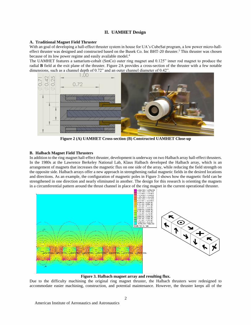
The UAMHET features a samarium-cobalt (SmCo) outer ring magnet and 0.125” inner rod magnet to produce the
radial B field at the exit plane of the thruster. Figure 2A provides a cross-section of the thruster with a few notable
dimensions, such as a channel depth of 0.72” and an outer channel diameter of 0.42”.
Figure 2 (A) UAMHET Cross-section (B) Constructed UAMHET Close-up
B. Halbach Magnet Field Thrusters
In addition to the ring magnet hall-effect thruster, development is underway on two Halbach array hall-effect thrusters.
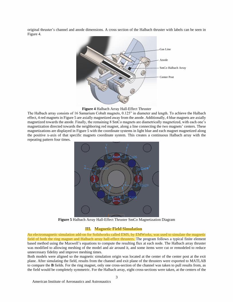
In the 1980s at the Lawrence Berkeley National Lab, Klaus Halbach developed the Halbach array, which is an
arrangement of magnets that increases the magnetic flux on one side of the array, while reducing the field strength on
the opposite side. Halbach arrays offer a new approach in strengthening radial magnetic fields in the desired locations
and directions. As an example, the configuration of magnetic poles in Figure 3 shows how the magnetic field can be
strengthened in one direction and nearly eliminated in another. The design for this research is orienting the magnets
in a circumferential pattern around the thrust channel in place of the ring magnet in the current operational thruster.
Figure 3. Halbach magnet array and resulting flux.
Due to the difficulty machining the original ring magnet thruster, the Halbach thrusters were redesigned to
accommodate easier machining, construction, and potential maintenance. However, the thruster keeps all of the
American Institute of Aeronautics and Astronautics
3
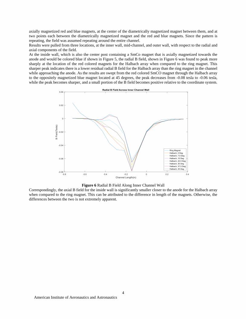
original thruster’s channel and anode dimensions. A cross section of the Halbach thruster with labels can be seen in
Figure 4.
Figure 4 Halbach Array Hall-Effect Thruster
The Halbach array consists of 16 Samarium Cobalt magnets, 0.125” in diameter and length. To achieve the Halbach
effect, 4 red magnets in Figure 5 are axially magnetized away from the anode. Additionally, 4 blue magnets are axially
magnetized towards the anode. Finally, the remaining 8 SmCo magnets are diametrically magnetized, with each one’s
magnetization directed towards the neighboring red magnet, along a line connecting the two magnets’ centers. These
magnetizations are displayed in Figure 5 with the coordinate systems in light blue and each magnet magnetized along
the positive x-axis of that specific magnets coordinate system. This creates a continuous Halbach array with the
repeating pattern four times.
Figure 5 Halbach Array Hall-Effect Thruster SmCo Magnetization Diagram
III. Magnetic Field Simulation
An electromagnetic simulation add-on for Solidworks called EMS, by EMWorks, was used to simulate the magnetic
field of both the ring magnet and Halbach array hall-effect thrusters. The program follows a typical finite element
based method using the Maxwell’s equations to compute the resulting flux at each node. The Halbach array thruster
was modified to allowing meshing of the model and air around it, and some items were cut or remodeled to reduce
unnecessary fidelity and improve meshing times.
Both models were aligned so the magnetic simulation origin was located at the center of the center post at the exit
plane. After simulating the field, results from the channel and exit plane of the thrusters were exported to MATLAB
to compare the B fields. For the ring magnet, only one cross-section of the channel was taken to pull results from, as
the field would be completely symmetric. For the Halbach array, eight cross-sections were taken, at the centers of the
Center Post
SmCo Halbach Array
Anode
Gas Line
American Institute of Aeronautics and Astronautics
4
axially magnetized red and blue magnets, at the center of the diametrically magnetized magnet between them, and at
two points each between the diametrically magnetized magnet and the red and blue magnets. Since the pattern is
repeating, the field was assumed repeating around the entire channel.
Results were pulled from three locations, at the inner wall, mid-channel, and outer wall, with respect to the radial and
axial components of the field.
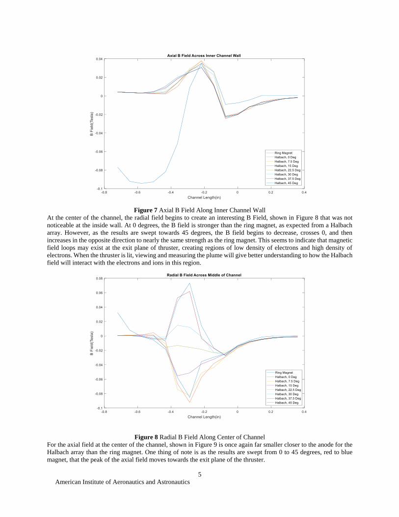
At the inside wall, which is also the center post containing a SmCo magnet that is axially magnetized towards the
anode and would be colored blue if shown in Figure 5, the radial B field, shown in Figure 6 was found to peak more
sharply at the location of the red colored magnets for the Halbach array when compared to the ring magnet. This
sharper peak indicates there is a lower residual radial B field for the Halbach array than the ring magnet in the channel
while approaching the anode. As the results are swept from the red colored SmCO magnet through the Halbach array
to the oppositely magnetized blue magnet located at 45 degrees, the peak decreases from -0.08 tesla to -0.06 tesla,
while the peak becomes sharper, and a small portion of the B field becomes positive relative to the coordinate system.
Figure 6 Radial B Field Along Inner Channel Wall
Correspondingly, the axial B field for the inside wall is significantly smaller closer to the anode for the Halbach array
when compared to the ring magnet. This can be attributed to the difference in length of the magnets. Otherwise, the
differences between the two is not extremely apparent.
American Institute of Aeronautics and Astronautics
5
Figure 7 Axial B Field Along Inner Channel Wall
At the center of the channel, the radial field begins to create an interesting B Field, shown in Figure 8 that was not
noticeable at the inside wall. At 0 degrees, the B field is stronger than the ring magnet, as expected from a Halbach
array. However, as the results are swept towards 45 degrees, the B field begins to decrease, crosses 0, and then
increases in the opposite direction to nearly the same strength as the ring magnet. This seems to indicate that magnetic
field loops may exist at the exit plane of thruster, creating regions of low density of electrons and high density of
electrons. When the thruster is lit, viewing and measuring the plume will give better understanding to how the Halbach
field will interact with the electrons and ions in this region.
Figure 8 Radial B Field Along Center of Channel
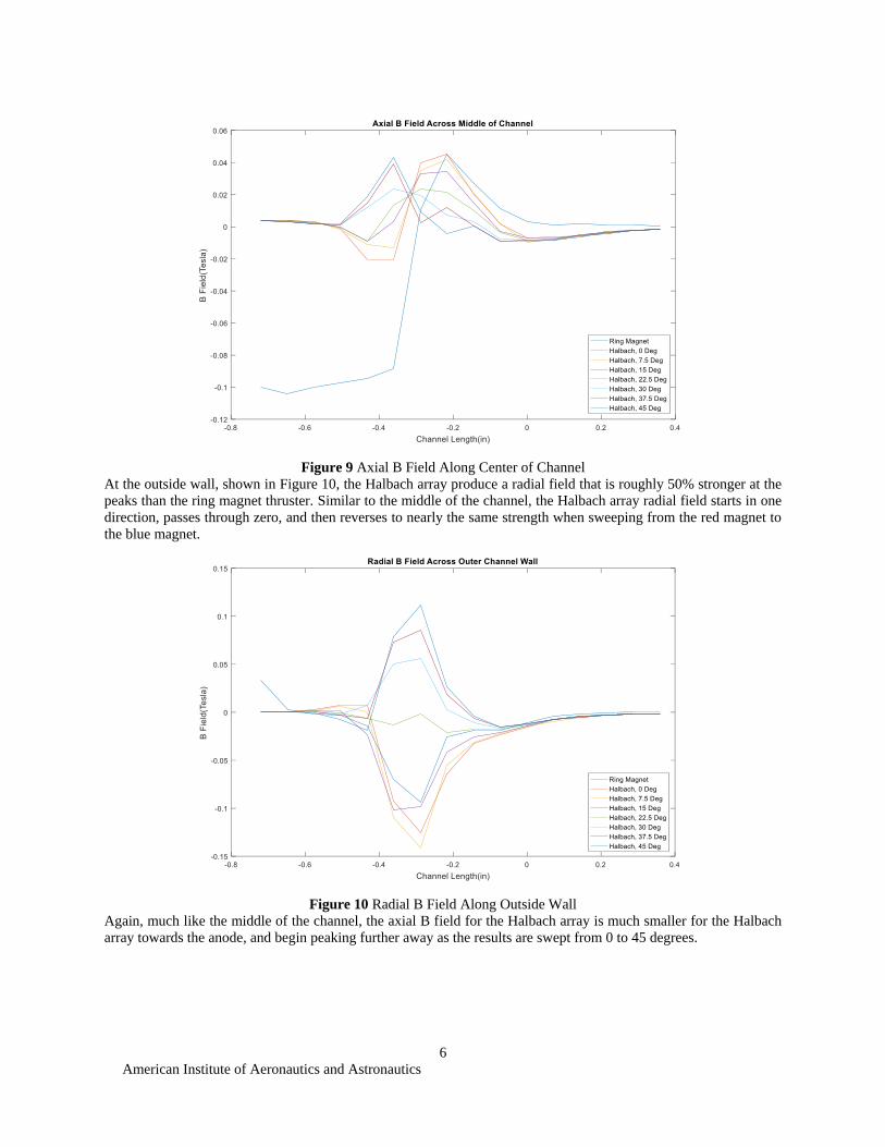
For the axial field at the center of the channel, shown in Figure 9 is once again far smaller closer to the anode for the
Halbach array than the ring magnet. One thing of note is as the results are swept from 0 to 45 degrees, red to blue
magnet, that the peak of the axial field moves towards the exit plane of the thruster.
American Institute of Aeronautics and Astronautics
6
Figure 9 Axial B Field Along Center of Channel
At the outside wall, shown in Figure 10, the Halbach array produce a radial field that is roughly 50% stronger at the
peaks than the ring magnet thruster. Similar to the middle of the channel, the Halbach array radial field starts in one
direction, passes through zero, and then reverses to nearly the same strength when sweeping from the red magnet to
the blue magnet.
Figure 10 Radial B Field Along Outside Wall
Again, much like the middle of the channel, the axial B field for the Halbach array is much smaller for the Halbach
array towards the anode, and begin peaking further away as the results are swept from 0 to 45 degrees.

American Institute of Aeronautics and Astronautics
7
Figure 11 Axial B Field Along Outside Wall
With the results gathered from the magnetic simulation of the Halbach array, a very asymmetric plume is expected to
form, with regions of high and low density for both the electrons and ions. Sweeping across one plane of the thruster
with a faraday will not be sufficient to characterize the plume. Either the thruster will need to be rotated multiple times
around the centerline, or a much more complicated translation system will be needed to sweep the 180 degree arcs in
multiple locations of the plume
IV. Experimental Progress
These experiments discussed in this paper takes place at the University of Alabama (UA) SPOT lab in Tuscaloosa,
AL. The vacuum space environment simulator, shown in Figure 12 maintains a base pressure of 2E-5 torr, and
approximately 5E-5 torr while operating the UAMHET and corresponding cathode. This cylindrical vacuum chamber

American Institute of Aeronautics and Astronautics
8
(2m x 3m) provides ample space for spacecraft hardware and instrumentation and is pumped with a Varian HS-20
Diffusion pump and Trivac D45BCS roughing pump.
Figure 12. UA SPOT lab vacuum chamber.
The UAMHET had its first successful ignition in early May, operating for a total of 3 hours before being turned off
to begin setting up the vacuum chamber for an axial centerline Faraday sweep. The UAMHET can be seen operating
in Figure 13 on the right, with the lanthanum hexaboride hollow cathode operating on the left. The 24 watt operating
parameters are listed in Table 1.
Figure 13 UAMHET Operating at 24W
American Institute of Aeronautics and Astronautics
9
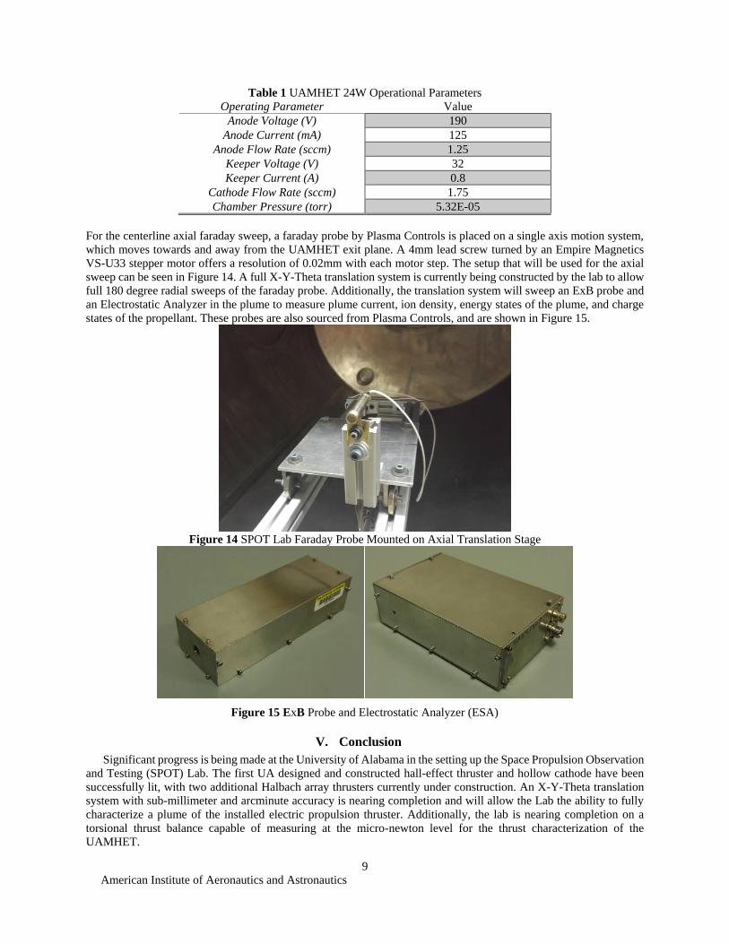
Table 1 UAMHET 24W Operational Parameters
Operating Parameter Value
Anode Voltage (V) 190
Anode Current (mA) 125
Anode Flow Rate (sccm) 1.25
Keeper Voltage (V) 32
Keeper Current (A) 0.8
Cathode Flow Rate (sccm) 1.75
Chamber Pressure (torr) 5.32E-05
For the centerline axial faraday sweep, a faraday probe by Plasma Controls is placed on a single axis motion system,
which moves towards and away from the UAMHET exit plane. A 4mm lead screw turned by an Empire Magnetics
VS-U33 stepper motor offers a resolution of 0.02mm with each motor step. The setup that will be used for the axial
sweep can be seen in Figure 14. A full X-Y-Theta translation system is currently being constructed by the lab to allow
full 180 degree radial sweeps of the faraday probe. Additionally, the translation system will sweep an ExB probe and
an Electrostatic Analyzer in the plume to measure plume current, ion density, energy states of the plume, and charge
states of the propellant. These probes are also sourced from Plasma Controls, and are shown in Figure 15.
Figure 14 SPOT Lab Faraday Probe Mounted on Axial Translation Stage
V. Conclusion
Significant progress is being made at the University of Alabama in the setting up the Space Propulsion Observation
and Testing (SPOT) Lab. The first UA designed and constructed hall-effect thruster and hollow cathode have been
successfully lit, with two additional Halbach array thrusters currently under construction. An X-Y-Theta translation
system with sub-millimeter and arcminute accuracy is nearing completion and will allow the Lab the ability to fully
characterize a plume of the installed electric propulsion thruster. Additionally, the lab is nearing completion on a
torsional thrust balance capable of measuring at the micro-newton level for the thrust characterization of the
UAMHET.
Figure 15 ExB Probe and Electrostatic Analyzer (ESA)
American Institute of Aeronautics and Astronautics
10
The Halbach permanent magnet array offers a potentially unique magnetic field for the UAMHET. This field will
need to be tested and characterized first before conclusions can be drawn on the impact it has on the thruster’s thrust
and efficiency parameters. This characterization is expected to occur in August of 2017.
References 1 de La Harpe, J.D., Branam, R., Huffman, R., Paintal, S. and Tedrake, R., “-Hall Effect Thruster Characterization,”
AIAA-2011-524, 49th AIAA Aerospace Sciences Meeting including the New Horizons Forum and Aerospace
Exposition, Orlando, Florida, Jan. 4-7, 2011. 2 Goebel, D. M. and Katz, I. Fundamentals of Electric Propulsion: Ion and Hall Thrusters. John Wiley & Sons,
Hoboken, 2008. 3 Paintel, S., “Micro-Hall Thruster Proof of Concept,” May 2010, Busek, Co., Inc. 4 Selstrom, J.J. "Thrust and Performance Study of Micro Pulsed Plasma Thrusters," MS Thesis, Air Force Institute of
Technology, March 2010. 5 R. R. Hofer, R. S. Jankovsky, and A. D. Gallimore, “High-Specific Impulse Hall Thrusters, Part 1: Influence of
Current Density and Magnetic Field,” Journal of Propulsion and Power, vol. 22, no. 4, pp. 721-731, 2006.