exam review - utah review acronyms ... system monitoring to ensure drinking water is safe monitor...
TRANSCRIPT
1
Operation and Maintenance
Exam Review
Acronyms� GPM= gallons per minute
� MGD= million gallons per day
� TTHM= total trihalomethane
� PSI= pounds per square inch
� NTU= Nephelometric Turbidity Unit
� mg/L= milligrams per litre or ppm= parts per million are the same
� TON= Threshold Odor Number for odor in the water. Should be conducted at 60 degrees C
System Monitoring
To Ensure Drinking Water is safe monitor for:
� Bacteria
� Turbidity
� Chlorine residual
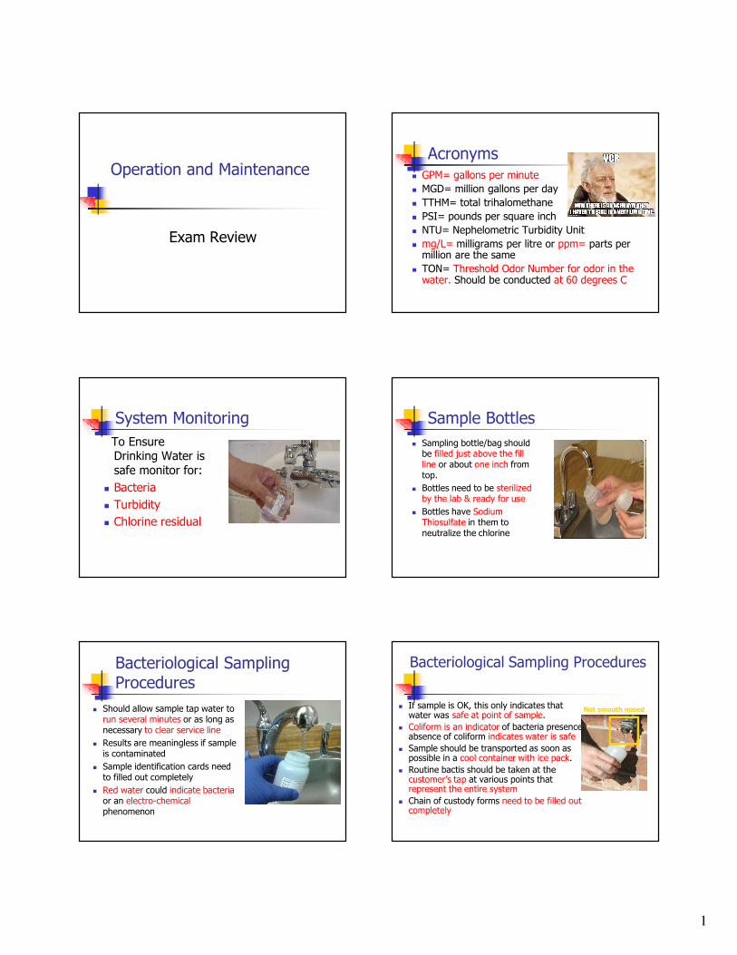
Sample Bottles
� Sampling bottle/bag should be filled just above the fill line or about one inch from top.
� Bottles need to be sterilized by the lab & ready for use
� Bottles have Sodium Thiosulfate in them to neutralize the chlorine
Bacteriological SamplingProcedures
� Should allow sample tap water to run several minutes or as long as necessary to clear service line
� Results are meaningless if sample is contaminated
� Sample identification cards need to filled out completely
� Red water could indicate bacteriaor an electro-chemicalphenomenon
Bacteriological Sampling Procedures
� If sample is OK, this only indicates that water was safe at point of sample.
� Coliform is an indicator of bacteria presence, absence of coliform indicates water is safe
� Sample should be transported as soon as possible in a cool container with ice pack.
� Routine bactis should be taken at the customer’s tap at various points that represent the entire system
� Chain of custody forms need to be filled out completely
Not smooth nosed
2
Composite Sample
� A series of grab samplestaken from the same sampling point at different times and mixed together
� Grab samples represent instantaneous conditions at the time and location the sample was taken
Nitrates
� Fertilizing lawns and farms can cause elevated levels of nitrates
� Nitrates cause Methemoglobinemia known as “blue baby”syndrome
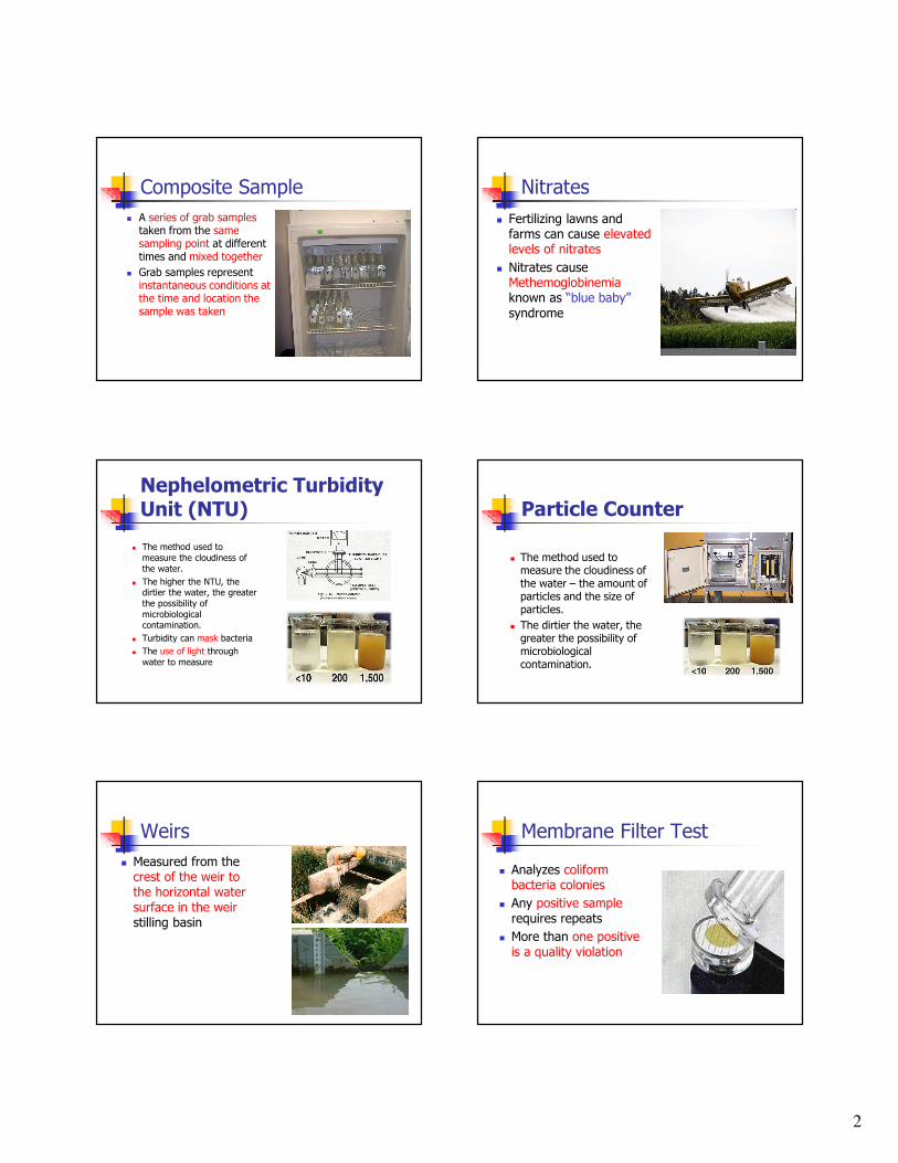
Nephelometric Turbidity Unit (NTU)
� The method used to
measure the cloudiness of
the water.
� The higher the NTU, the dirtier the water, the greater
the possibility of
microbiological contamination.
� Turbidity can mask bacteria
� The use of light through
water to measure
Particle Counter
� The method used to measure the cloudiness of the water – the amount of particles and the size of particles.
� The dirtier the water, the greater the possibility of microbiological contamination.
Weirs
� Measured from the crest of the weir to the horizontal water surface in the weir stilling basin
Membrane Filter Test
� Analyzes coliform bacteria colonies
� Any positive sample requires repeats
� More than one positive is a quality violation

3
GWR
� TC+ bacterial Samples
� Requires Triggered Source Water sample (TSW)
� All sources that were in operation at time of +TC sample
� You can email DDW on sources not sampled –not running
� Test for fecal coliform
GWR continued
� 5 additional samples if first Triggered Source Water sample is Fecal+
� 2 or more sourcesrequires you to submit new sample site plan
� Correct significant deficiencies within 120 days
New Minimum PSI Standards
� Water pressure is measured in psi
� Maintain minimum of 20 psi at all times
� 20 psi during fire flow
� 30 psi during peak instantaneous demand
� 40 psi during peak daydemand
Sanitary Surveys Performed By
� Executive Secretary shall ensure a sanitary survey is conducted at least every 3 years
� Division of Drinking Water
� DEQ District Engineers
� Local Health Departments
� Forest Service Engineers
� Utah Rural Water Association staff
� Consulting Engineers
� Others authorized by Executive Secretary
Aesthetics
� Means attractive or appealing.
� With respect to water it means taste, odor, or coloration of the water.
� Things that affect this are extreme hardness or high total dissolved solids
� Effects range from bad smell and poor taste to causing stains on laundry and/or fixtures
� Hydrogen sulfide causes rotten egg odors
Water Storage Reservoirs
� Provides adequate water to the water system during average and peak demands
� Provides adequate pressuresthroughout the water systems
� Must be covered to prevent algae and bacterial growth
� Reserve storage
� Fire protection
� Most susceptible to degradation from external sources
Measured as volume

4
Screen Sizes
� #14 mesh for air vents and air vacuum release valve
� Air vac vent pipe above the flood line
� #4 mesh for overflow and drain lines
� #14 mesh = 14 squares per inch
� #4 mesh = 4 squares per inch
#14
#4
Pressure Tanks
� Blow off valves should be able to discharge at pumping rate
� Frequent on & off cycling of the booster pumpshows lack of air in tank & is water logged
Blow off
Reservoir Maintenance
� Comprehensive inspections and cleaning inside of tank should be done every 3 to 5 years or more frequently
� Repair
� Disinfect
� Take bacti’s
� Inspect Vents- for ice, screen holes, etc.
� Long & short life coatings for tank interiors
Surface Reservoirs
� Most significant reason for turn over is a change in surface water temperature and density
� Act as pre-sedimentation basins
� Water is most dense at 39.2 deg F, 4 deg C.
� Colder water has more oxygen
SCBA
� Self Contained Breathing Apparatus
� Always use when around gas leaks & oxygen deficient areas
Confined Spaces
� Reservoir site entry
� Sources- where chemicals are stored
� Vehicles- Keep away from manhole
� Vaults- Carbon Monoxide (CO) will settle to the floor.
� Minimum oxygen level of 19.5%

5
Chemical Handling
� All chemicals should be stored according to the manufacturer’sspecs
� Chemical compound has multiple chemicals such as calcium carbonate
Tank Maintenance
� Cycling of water (movement)to prevent freezing
� Cathodic protection to protect from corrosion
� Age of the water in the tank attributed to quality problems cause by low demand or short circuiting
� Sandblasting is recommended for preparing interior of tank
� Should be sampled for possible water quality changes
Disinfection of Reservoirs
� Facility disinfected before it is put on line
� Disinfected after cleaning, repair, painting
� AWWA C652
� Full reservoir – 10 mg/l/ 24 hours
� 6 hour/24 hour
� Spraying interior – 200 mg/l – 30 minute detention time
� Fill 5 %/ 50 ppm – 6 hours, then fill rest of tank <2 ppm – 24 hours
� At least one bacteriological sample(TC-)
Water Distribution Systems� Leaks get worse� Do a water audit to identify water &
revenue losses� Leak surveys should be done during low
flows� Cracked mains should be replaced
� Pressures can be measured at a fire hydrant or pressure regulating station
� Distribution system pressures� 20 psi at all times for peak instantaneous flows
� Minimum Water main size� 8 inch with fire hydrants
� Unless you have an engineer signature to buy off on it
� 4 inch without fire hydrants
Distribution Systems
� Water mains
� 10 Feet horizontal distance from sewer main
� Water main and sewer mains must cross at least 18” of separation
� Water line is on top
� Water & sewer not installed in the same trench.
� Anaerobic growth develops in water devoid of oxygen causing odor problems
� Hydraulic adequacy determined by pressure measurements throughout system at various times
� Looped to prevent dead ends, quality problems, and better flow
Customer Service Connection
� Corporation valve (corp stop) for customer service line shut off
� ¾” most common customer service connection
� Thaw service line with hot water or warm air
� Consider flow rate & pressure for sizing
6
New Main Installation
� Jacking and Boring is the most common technique for the construction of a pipeline under a heavily traveled highway or railway without disrupting the traffic
New Water Mains
� Steps taken to put into service� Pressure and leak test� Flush out debris� Keep pipe clean� Disinfect the pipe – AWWA C651� Take a chlorine residual� Flush highly chlorinated water� Bacteriological Samples –
� 2 samples taken 24 hours apart. Why?
� Special conditions
� Keep ends of pipe plugged when unmanned
Pressure Testing New Water Main
� Should be done at 50% higher than normal operating pressure or 150 psi whichever is larger
� Duration 4 Hours
� New connections installed under pressure are calledhot taps
Water Mains
� Never shut main valve completely (may cause a back siphon)
� Disinfect with tablets or granular @ 25 mg/L for 24 hours
� Continuous Feed – 10 mg/L after 24 hours
� Fill main with water
� Flush out debris
� Fill with chlorinated water
Backfilling Mains
� Notify other utilities or blue stakes before digging
� Soil placed equally on both sides half way up of the pipe in layers hand tamped
� Pipe should covered by about 12” of soil
� “Well Point” used to dewater trenches
� Shallow mains more susceptible to freezing
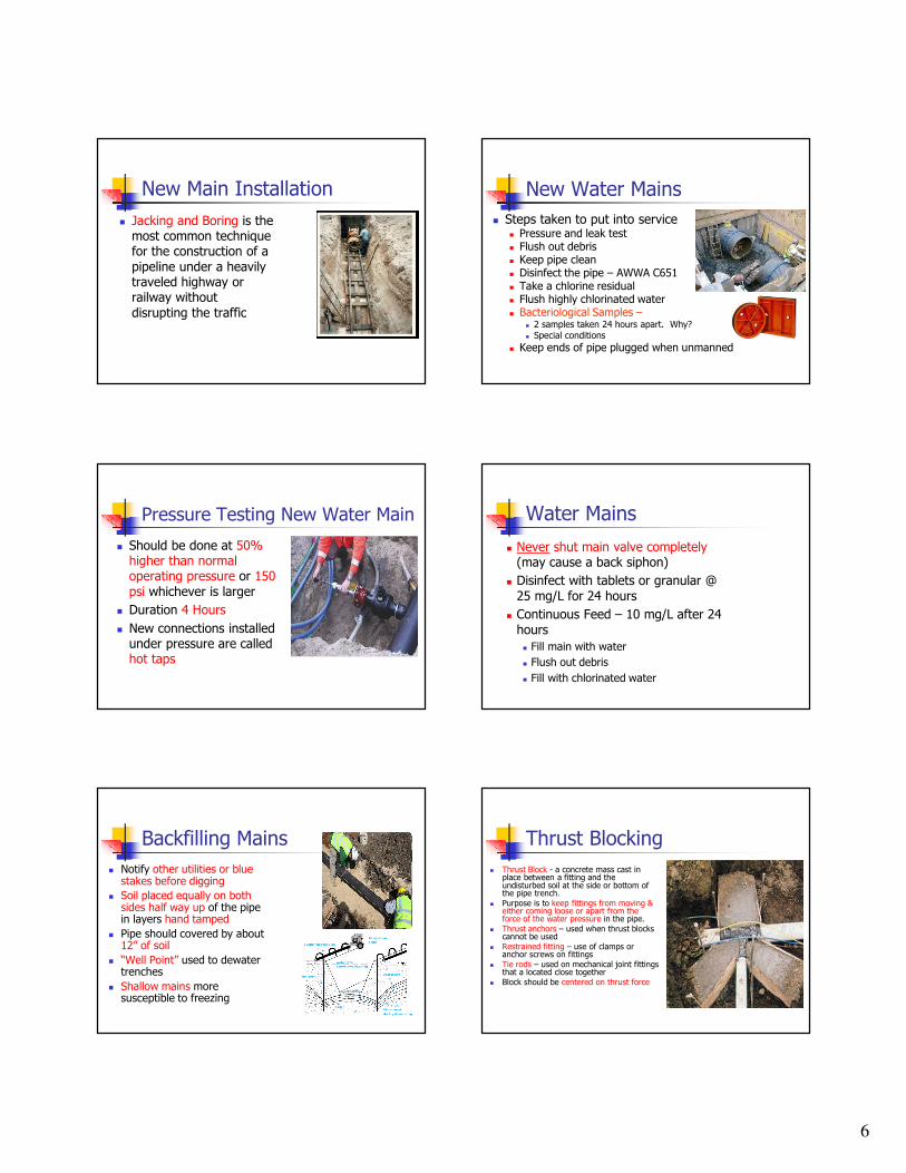
Thrust Blocking
� Thrust Block - a concrete mass cast in place between a fitting and the undisturbed soil at the side or bottom of the pipe trench.
� Purpose is to keep fittings from moving & either coming loose or apart from the force of the water pressure in the pipe.
� Thrust anchors – used when thrust blocks cannot be used
� Restrained fitting – use of clamps or anchor screws on fittings
� Tie rods – used on mechanical joint fittings that a located close together
� Block should be centered on thrust force

7
Thrust Blocks
� Should be place behind the foot of the hydrant at the flow line
Fire Hydrants
� Hydrant bury is the distance below the ground to the main connection.
� Because of increased population growth and scaling of pipes, hydrant flow tests should be performed periodically & after major changes to distribution system
� Dropping a weighted string down the barrel of hydrant to check for water is called “Stringing”
� Nozzles are usually 2.5 and 4.5 inches
� Painted different colors to show flow
Hydrant Cap Color Codes
Class Color Water Flow (GPM)
� AA Light blue 1500 or more
� A Green 1000–1499
� B Orange 500–999
� C Red Less than 500
Fire Hydrants
� Flushing hydrants can stir up silt creating water quality problems
� Should be tested for flow with a pitot gauge
� Flow tests show quantity of available water
� Should be metered by contractors to account for water use
Dry Barrel Hydrants
� Drain hole drains barrel to protect from freezing
� Partially open drain valve would cause excessive leakage from drain hole
� Must be tested for leakage withmain valve open & caps on
� Use a listening device to check for leaking valve seat
� Operating valve located in the base of the hydrant
Flush Hydrants
� Means hydrant is flush with a wall or ground
� For areas where post hydrants are not suitable

8
Flushing the System
� Dead End Systems
� Water Quality Issues
� Customer Complaints
� Be mindful of environmental concerns
� During periods of low demand
Flushing Procedure
� Notify customers thru billing, newspaper, or electronic media of times and places affected or anything affecting the condition of their water
� Explain Intent Of Flushing
� Notify Hospitals, Dialysis Patients, Restaurants, Laundromats, & Others That May Be Affected
Flushing The System
� When The System Has Become Contaminated
� Newly Installed Or Repaired Mainlines
Flushing Hydrants
� Helps remove taste & odor causing deposits
� Helps remove encrustations that may restrict flow
� Helps remove sand, rust, & biological materials that cause water quality problems
FLUSHING PROCEDURE
� Try To Avoid Flooding Traffic Areas
� Open Hydrant Fully For 5 To 10 Minutes To Stir Up Deposits
� Don’t let nearby areas drop below 20 psi to avoid negative pressures
� Record Pertinent Data: Odor, Water Appearance, Times, & Places, Etc.
Fire Fighters
� Fire fighters can createnegative pressures
� Dead end systems would likely haveinadequate flows for firemen

9
Valves
� All system valves should be exercised annually
� Purpose is to isolatesections of the system
Gate Valves
� Most commonly used valve in distribution system
� Gate Valve: Isolation only, should be either all the way open or all the way closed
� Cavitation (formation & collapse of bubbles) can occur
� Fully open has least amount of head loss from other valves
� Can be repacked without taking out of service
Globe Valves
� Best for flow control throttling, & pressure regulating
Butterfly Valves -
� Higher resistance to flow
� Operates easily & quickly
� They cost less than gate valves
� Used for flow control & isolation
Ball & Plug Valves Sluice Gate & Sleeve Valves

10
PRV Valves
� Pressure Sustaining/Reducing: maintain either upstream or downstream pressures depending on the position of the pilot screw.
� Need to be maintained periodically
� Help reduce water hammer
Pressure Reducing Valves
� Installed in parallel to handle high & low flows
Altitude Valve
� A good valve to regulate tank levels
� Altitude valve: opens when system psi drops below a certain pressure and closes when the reservoir reaches a predetermined level.
Pump Control Valves
� Allow pumps to be started & stopped against a closed valve
� Best method to control water hammer
Check Valves
� Keep flows going one direction
� Flow must be directional with pump discharge lines, customer service lines, and water treatment plants
Air Release Valves (air-vacs)
� Allow air in & out
� Should be placed athigh points in the system
� Need to be screened & protected from flooding
� Relief valve outlet12” above ground

11
Water Hammer
� Occurs when a valve is closed quickly or pump shuts down and causes the water pressures to rise and fall rapidly.
� Sounds like some hammering on pipe.
� Can damage pipes, causing them burst.
System Mapping
� Accurate mapping ensures the operators can locate the valvesand main lines in case of a main break or leak
pH� pH: expression that refers to the basic or acidic conditions of the water
� pH is measured on a scale from 0 to 14.
� Less than 7 is more acidic, greater than 7 is more basic or higher alkalinity 7 is neutral.
pH
� pH and alkalinity tests can be performed to assess the corrosiveness of the water
� Alkalinity expressed as Calcium Carbonate
� Chlorine lowers the pH & chlorine rate may need to be increased
Water Hardness
� Caused mainly by salts of calcium and magnesium, such as bicarbonate, carbonate, sulfate, chloride and nitrate.
� Causes formation of soap curds
� Deposits show chemical instability
� Deposits of scale in boilers & fixtures
� Damages in some industrial processes
� Objectionable tastes in water

12
Langlier Saturation Index (LSI)
� Measures corrosiveness of water� LSI (Carrier)Indication� -2.0 to less than -0.5: Serious corrosion or aggressive
� -0.5 to less than 0: Slightly corrosion but non-scale forming
� LSI = 0.0 Balanced but pitting corrosion possible� 0.0 to less than 0.5: Slightly scale forming and corrosive
� 0.5 to less than 2: Scale forming but non corrosive
Corrosive� Electrochemical phenomenon
� Measurements:
� Langelier index
� Positive number: Deposit
� Negative number: Corrosive
� Metal coupons used to measure corrosiveness of
water – determined by weight loss of coupon
� Adjustments can be accomplished by:
� Chemicals which increase or decrease the depositing, or
� Sequester the problem with the use of
polyphosphates
� pH/Alkalinity adjustment w/Lime, Sequestering &
Chelation
Alkalinity
� A measurement of the water’s capacity to neutralize an acid
� Alkalinity is determined by titrating to an end point with a pH meter or the use of the methyl orange test
� Use sulfuric acid to perform test
� Affects the coagulation process
� Insoluble calcium carbonate compoundscause build up of scale
� Hardness expressed as mg/L in CaCO3, to be considered soft should be 0 to 50 mg/L
Head Loss
� Valves, elbows, pipe characteristics, etc. contribute to loss of flows
� Pipe roughness coefficient tests to see if friction losses are increasing
� Bursting strength of pipe refers to pipe’s ability to withstand internal forces
Head Loss
� Friction head loss: caused by valves, bends, pipe roughness, etc.
� Friction headloss is in direct proportion to theincrease in the velocity of the water flow
� Various factors can slow down the velocity of water.
� Alkalinity expressed as Calcium Carbonate
FRICTIONAL HEADLOSS
� Energy used up by water movement
� Two Conditions that affect head loss:
1. Roughness of the pipe
2. Velocity of the water
. Two Conditions that affect Roughness:
1. Age – Condition
2. Type of pipe Materials

13
C-Factor
� Indicates the smoothness pipe material
� The higher the C value, the smoother the pipe.
� To calculate measure flow, pipe diameter, distance between two pressure gauges, and the friction losses between the gauges.
� 3 most common types of plastic pipe are PVC, PE, & ABS
� PVC least susceptible to corrosion
� C value reduced by tuberculation
PVC has higher C- factor than concrete
Water Loss
� Affected by: leaks, pressures, efficiency of the meter maintenance, attention given to leak reduction & unauthorized use of water
� Some systems 10% of the water produced
� Other systems not until 20%
Consumer Calls
� Persons name, address, & phone
� What’s the problem: taste, odor, discolor,etc.
� When was problem first noticed?
� Duration of problem?
� Are neighbors having same problems?
� Has it resulted in any illness?
� Has Local Health Dept. or DDW been notified?
� Can they get a sample in a clean glass?
Cross Connections
� Determined by the degree of hazard� Cross connection: a connection between a potable and an
unapproved source.� Two Types of Backflow:
Backsiphonage: backflow caused by a negative or below atmospheric pressure in a water system.
Backpressure: when users pressure is higher than the system pressure
� Water user is responsible to keep contaminants out of the water system
� Flush out debris and trapped air in newly installed assemblies
� An effective program helps minimize degradation of the water system
� Responsible for most waterborne disease outbreaks
Devices and Assemblies
� Keep contaminants out� Air Gap: a physical break between to connections. Minimum of 1” or two times the diameter of the pipe & safest method of backflow prevention
� Double Check Assembly: Has two independent internally loaded check valves, 2 shut off valves, & 4 test cocks.
Cross Connections
� Reduced Pressure Principle Assembly: For High Hazards, has 2 spring loaded check valves, a relief valve, 4 test cocks, and 2 shut off valves. Relief port can’t be submerged & installed 12” above floor
� Pressure Vacuum Breaker: internal check valve, an internal loaded air poppet, 2 shut off valves and 2 test cocks. Not designed for back pressure

14
Cross Connection
� Atmospheric Vacuum Breakers not designed to protect against back pressure
� Prior to the installation of any backflow prevention assembly or device owner should be advised thermal expansion hazards
Wire to Water Efficiency
� The combined efficiency of the pump and the motor together. Also called the over all efficiency.
� Water HP/Electrical HPx100%=over all efficiency
� The amount of energy required to overcome the inefficiencies of the pump and motor
Electric Motors� Upon start up an electric motor will
develop a torque to turn the pump shaft and impeller
� Torque causes motor to draw a high amperage
� Amperage drops once the pump is up to speed.
� To change rotation on 3 phase, switch any 2 leads
� Transformers step down voltage
� Circuit breakers protect from circuit overloads
Digital Multimeters
� Ohm meters measure resistance
� Volt meters measure voltage
� Amp meters measure current
� Tachometer would showpump speed
� Setting should be set to next highest level of what you measuring
Lightning Arrestor
� Becomes a low resistance conductor to ground when the line voltage exceeds a predetermined amount
� Used to protect equipment from lightning strikes.
� No device made to protect against a direct hit.
Power Sources
� Primary Sources- Power Company
� Auxiliary Sources-Diesel, Natural Gas, & Gasoline Powered Generators may be necessary in an emergency

15
Meter Sizing Considerations
� Pressure at the service connection
� Highest fixture in the building being
served
� Any back flow prevention device
� A 5/8 inch meter should be tested every 5 to 10 years.
� Meter should not have more than
20 psi of head loss.
� One inch and smaller meters
shouldn’t exceed 15 psi of head loss
Small Meter Installation
� Meter pit located on public property
� Meter pit relatively safe from vehicle & snow removalequipment
� Riser pipes should be 1 to 2 inches away from meter box walls
� Use of meter yoke� Use jumper cable to protect from electrical shock from piping in the home
Meter Accuracy
� Measure water flow� Worn meters will cause the meter to under register, allowing the customer to receive more water than they pay for.
� Unaccountable water loss is the term used in determining meter accuracy & leakage
� Over time a worn meter will cost the water system revenue.
� Formula: Meter Accuracy= (Meter,GPM)(100%)/Volume,GPM
Magnetic Meters
� Maintenance calibration should include flow at zero flow rate
Compound Meters
� For low to intermediate flows
� Occasionally high flows
Positive Displacement Meter
� Nutating disk: nutating means nodding. When the water flows the disk rotates.

16
Oscillating Piston Meter
� Displacement type
� Water flows into a chamber and displaces piston
� Oscillating circular motion moves meter
� Higher head loss than nutating disk
Velocity Meter & Venturi
� Mechanical rotors or propellers are turned by velocity of water to measure flow
� Venturi meters measure differential pressure & have no moving parts.
� Venturi meters are best forproviding uninterrupted flow
Velocity Meter
Iron
� Consumer complaints
� Can cause stains on laundry & fixtures
� Formation of iron bacteria that form slick slimes on pipe walls
� Taste and odor problems
� Reacts with chlorine increasing use
� Can be removed thru aeration, flushing & polyphosphates
� Mixed with manganese react withdissolved oxygen forming insoluble compounds
Manganese
� Iron mixed with manganese reacts with dissolved oxygen forming insoluble compounds
� Causes black stains
Electrolysis
� Decomposition of material by an outside electriccurrent
� Electric current caused bymovement of water in the line
� Cathodic protection installed to preventcorrosion
� Magnesium anodes help prevent galvanic corrosion
� Galvanic corrosion caused by connecting dissimilar metals
� Metal coupons evaluated for weigh loss
Tanks – Cathodic Protection
Anodes

17
Ground Water
� Water passing thru porous soil is called percolation
� Water bearing geological formation is called an aquifer
Wells
� Sanitary seal – prevents contamination from entering
� Well casing – pipe placed inside well to keep it open
� Grout – mixture of cement, water and sand pumped between the casing & the drilling hole (annulus)
� Specific capacity is the well yield in GPM per foot of drawdown
Well Maintenance
� Water needs to be pumped to waste until it clears up
ACCURATE RECORD KEEPING
� Shows decreases in flow and pressures
� Insures each piece of equipment receives proper attention to prolong its life
� Shows when preventive maintenance or repairs were last performed
� Reduces liability to operator & improves customer service
� Work orders best way to track system maintenance
The end
� Contact Information
� Kim Dyches
� 801-536-4202