ex d csc, efsco, efdc, emha - cortemgroup.com · ex d a.1 ed.2018 command and control stations...
TRANSCRIPT

Ex d
ED.2018A.1
Command and control stations ‘Ex d’
CSC, EFSCO, EFDC, EMHA
- Group IIC- Zone 1, 2, 21, 22- Aluminium alloy, stainless steel or cast iron enclosures- Category 2GD or M2
Cast metal fixing lugs
Stainless steel screws
RAL7035 polyester coating
Earthing bolt with rod to prevent cable from twisting
Ex d
ED.2018 A.2
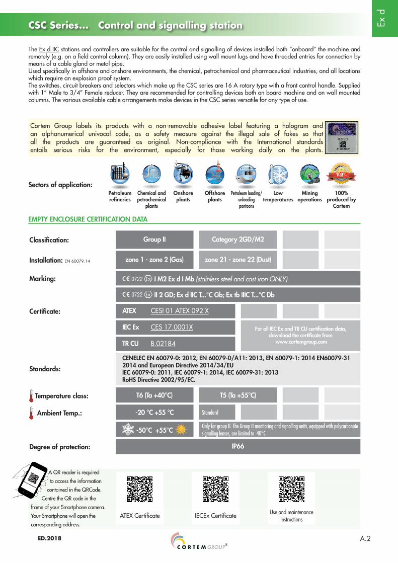
The Ex d IIC stations and controllers are suitable for the control and signalling of devices installed both “onboard” the machine and remotely (e.g. on a field control column). They are easily installed using wall mount lugs and have threaded entries for connection by means of a cable gland or metal pipe.Used specifically in offshore and onshore environments, the chemical, petrochemical and pharmaceutical industries, and all locations which require an explosion proof system.The switches, circuit breakers and selectors which make up the CSC series are 16 A rotary type with a front control handle. Supplied with 1” Male to 3/4” Female reducer. They are recommended for controlling devices both on board machine and on wall mounted columns. The various available cable arrangements make devices in the CSC series versatile for any type of use.
Sectors of application:
EMPTY ENCLOSURE CERTIFICATION DATA
Petroleum refineries
Chemical and petrochemical
plants
Onshore plants
Offshore plants
Petroleum loading/unloading pontoons
Low temperatures
Mining operations
100% produced by
Cortem
Classification: Group II Category 2GD/M2
Installation: EN 60079.14 zone 1 - zone 2 (Gas) zone 21 - zone 22 (Dust)
Marking: I M2 Ex d I Mb (stainless steel and cast iron ONLY)
II 2 GD; Ex d IIC T...°C Gb; Ex tb IIIC T...°C Db
Certificate: ATEX CESI 01 ATEX 092 X
IEC Ex CES 17.0001X For all IEC Ex and TR CU certification data, download the certificate from
www.cortemgroup.comTR CU B.02184
Standards:
CENELEC EN 60079-0: 2012, EN 60079-0/A11: 2013, EN 60079-1: 2014 EN60079-31 2014 and European Directive 2014/34/EUIEC 60079-0: 2011, IEC 60079-1: 2014, IEC 60079-31: 2013RoHS Directive 2002/95/EC.
Temperature class: T6 (Ta +40°C) T5 (Ta +55°C)
Ambient Temp.: -20 °C +55 °C Standard
-50°C +55°C Only for group II. The Group II monitoring and signalling units, equipped with polycarbonate signalling lenses, are limited to -40°C
Degree of protection: IP66
CSC Series... Control and signalling station
Cortem Group labels its products with a non-removable adhesive label featuring a hologram and an alphanumerical univocal code, as a safety measure against the illegal sale of fakes so that all the products are guaranteed as original. Non-compliance with the International standards entails serious risks for the environment, especially for those working daily on the plants.
ATEX Certificate IECEx Certificate Use and maintenance instructions
A QR reader is required
to access the information
contained in the QRCode.
Centre the QR code in the
frame of your Smartphone camera.
Your Smartphone will open the
corresponding address.
Ex d
ED.2018A.3
CSC Series... Control and signalling station
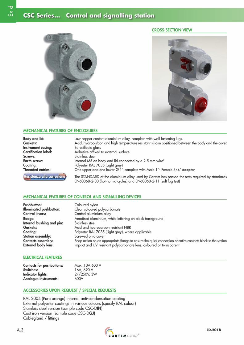
CROSS-SECTION VIEW
MECHANICAL FEATURES OF ENCLOSURES
Body and lid: Low copper content aluminium alloy, complete with wall fastening lugs.Gaskets: Acid, hydrocarbon and high temperature resistant silicon positioned between the body and the coverInstrument casing: Borosilicate glassCertification label: Adhesive affixed to external surfaceScrews: Stainless steelEarth screw: Internal M5 on body and lid connected by a 2.5 mm wire2
Coating: Polyester RAL 7035 (Light grey)Threaded entries: One upper and one lower Ø 1” complete with Male 1”- Female 3/4” adapter
: The STANDARD of the aluminium alloy used by Cortem has passed the tests required by standards EN60068-2-30 (hot-humid cycles) and EN60068-2-11 (salt fog test)
MECHANICAL FEATURES OF CONTROL AND SIGNALLING DEVICES
Pushbutton: Coloured nylonIlluminated pushbutton: Clear coloured polycarbonateControl levers: Coated aluminium alloyBadge: Anodised aluminium, white lettering on black backgroundInternal bushing and pin: Stainless steel Gaskets: Acid and hydrocarbon resistant NBRCoating: Polyester RAL 7035 (Light grey), where applicableStation assembly: Screwed onto coverContacts assembly: Snap action on an appropriate flange to ensure the quick connection of entire contacts block to the stationExternal body lens: Impact and UV resistant polycarbonate lens, coloured or transparent
RAL 2004 (Pure orange) internal anti-condensation coatingExternal polyester coatings in various colours (specify RAL colour)Stainless steel version (sample code CSC-DIN)Cast iron version (sample code CSC-DGJ)Cablegland / fittings
Contacts for pushbuttons: Max. 10A 600 VSwitches: 16A, 690 VIndicator lights: 24/250V, 3WAnalogue instruments: 600V
ACCESSORIES UPON REQUEST / SPECIAL REQUESTS
ELECTRICAL FEATURES
Ex d
ED.2018 A.4
CSC Series... Control and signalling station
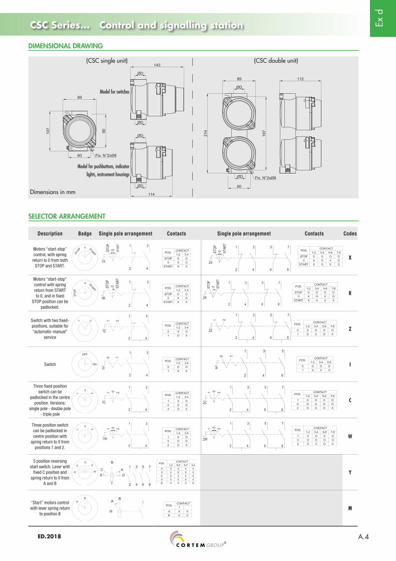
Description Badge Single pole arrangement Contacts Single pole arrangement Contacts Codes
Motors “start-stop” control, with spring
return to 0 from both STOP and START.
X
Motors “start-stop” control with spring return from START to 0, and in fixed
STOP position can be padlocked.
R
Switch with two fixed-positions, suitable for “automatic-manual”
service
Z
Switch I
Three fixed position switch can be
padlocked in the centre position. Versions:
single pole - double pole - triple pole
C
Three position switch can be padlocked in centre position with
spring return to 0 from positions 1 and 2.
W
5 position reversing start switch. Lever with
fixed C position and spring return to 0 from
A and B
Y
“Start” motors control with lever spring return
to position BM
Dimensions in mm
(CSC single unit)
Model for switches
Model for pushbuttons, indicator lights, instrument housings
(CSC double unit)
DIMENSIONAL DRAWING
SELECTOR ARRANGEMENT

Ex d
ED.2018A.5
Illustration EntryØD Description Diagram Weight
Kg Codes
1” ISO 7/1
Single body: double pushbutton 0.85
CSC-D
1” NPT CSC-DN
1” ISO 7/1
Single body: illuminated pushbutton 0.90
CSC-G
1” NPT CSC-GN
1” ISO 7/1
Double body: double illuminated pushbutton 1.60
CSC-GG
1” NPT CSC-GGN
1” ISO 7/1
Single body: single signal lamp 0.80
CSC-L
1” NPT CSC-LN
1” ISO 7/1
Double body: double signal lamp 1.57
CSC-LL
1” NPT CSC-LLN
1” ISO 7/1 Single body: single pushbutton(1NA+1NC) 0.74
CSC-P
1” NPT CSC-PN
1” ISO 7/1 Single body: single pushbutton 2NA 2NC 0.88
CSC-2P
1” NPT CSC-2PN
1” ISO 7/1
Double body: pushbutton + indicator light 1.63
CSC-PL
1” NPT CSC-PLN
1” ISO 7/1
Double body: two pushbuttons 1.69
CSC-PP
1” NPT CSC-PPN
1” ISO 7/1 Single body: single maintained pushbutton(maintained) (1NA+1NC) 0.90
CSC-B
1” NPT CSC-BN
1” ISO 7/1 Single body: single maintained pushbutton (maintained) (2NA+2NC) 0.92
CSC-2B
1” NPT CSC-2BN
CSC Series... Control and signalling station
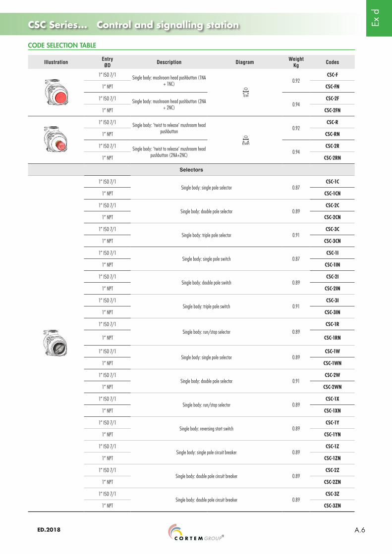
CODE SELECTION TABLE
Ex d
ED.2018 A.6
Illustration EntryØD Description Diagram Weight
Kg Codes
1” ISO 7/1 Single body: mushroom head pushbutton (1NA + 1NC) 0.92
CSC-F
1” NPT CSC-FN
1” ISO 7/1 Single body: mushroom head pushbutton (2NA + 2NC) 0.94
CSC-2F
1” NPT CSC-2FN
1” ISO 7/1 Single body: ‘twist to release’ mushroom head pushbutton 0.92
CSC-R
1” NPT CSC-RN
1” ISO 7/1 Single body: ‘twist to release’ mushroom head pushbutton (2NA+2NC) 0.94
CSC-2R
1” NPT CSC-2RN
Selectors
1” ISO 7/1Single body: single pole selector 0.87
CSC-1C
1” NPT CSC-1CN
1” ISO 7/1Single body: double pole selector 0.89
CSC-2C
1” NPT CSC-2CN
1” ISO 7/1Single body: triple pole selector 0.91
CSC-3C
1” NPT CSC-3CN
1” ISO 7/1Single body: single pole switch 0.87
CSC-1I
1” NPT CSC-1IN
1” ISO 7/1Single body: double pole switch 0.89
CSC-2I
1” NPT CSC-2IN
1” ISO 7/1Single body: triple pole switch 0.91
CSC-3I
1” NPT CSC-3IN
1” ISO 7/1Single body: run/stop selector 0.89
CSC-1R
1” NPT CSC-1RN
1” ISO 7/1Single body: single pole selector 0.89
CSC-1W
1” NPT CSC-1WN
1” ISO 7/1Single body: double pole selector 0.91
CSC-2W
1” NPT CSC-2WN
1” ISO 7/1Single body: run/stop selector 0.89
CSC-1X
1” NPT CSC-1XN
1” ISO 7/1Single body: reversing start switch 0.89
CSC-1Y
1” NPT CSC-1YN
1” ISO 7/1Single body: single pole circuit breaker 0.89
CSC-1Z
1” NPT CSC-1ZN
1” ISO 7/1Single body: double pole circuit breaker 0.89
CSC-2Z
1” NPT CSC-2ZN
1” ISO 7/1Single body: double pole circuit breaker 0.89
CSC-3Z
1” NPT CSC-3ZN
CODE SELECTION TABLE
CSC Series... Control and signalling station

Ex d
ED.2018A.7
Combinations
Illustration EntryØD Description Weight
Kg Codes
1” ISO 7/1 Double body: single pole changeover switch + indicator light 1.65
CSC-1CL
1” NPT CSC-1CLN
1” ISO 7/1 Double body: double pole changeover switch + indicator light 1.67
CSC-2CL
1” NPT CSC-2CLN
1” ISO 7/1 Double body: triple pole changeover switch + indicator light 1.69
CSC-3CL
1” NPT CSC-3CLN
1” ISO 7/1Double body: pushbutton + single pole selector 1.70
CSC-P1C
1” NPT CSC-P1CN
1” ISO 7/1Double body: pushbutton + double pole selector 1.72
CSC-P2C
1” NPT CSC-P2CN
1” ISO 7/1Double body: pushbutton + triple pole selector 1.74
CSC-P3C
1” NPT CSC-P3CN
1” ISO 7/1Double body: single pole circuit breaker + indicator light 1.65
CSC-1ZL
1” NPT CSC-1ZLN
1” ISO 7/1Double body: double pole circuit breaker + indicator light 1.67
CSC-2ZL
1” NPT CSC-2ZLN
1” ISO 7/1Double body: triple pole circuit breaker + indicator light 1.65
CSC-3ZL
1” NPT CSC-3ZLN
1” ISO 7/1Double body: pushbutton + single pole circuit breaker 1.70
CSC-P1Z
1” NPT CSC-P1ZN
1” ISO 7/1Double body: pushbutton + double pole circuit breaker 1.72
CSC-P2Z
1” NPT CSC-P2ZN
1” ISO 7/1Double body: pushbutton + triple pole circuit breaker 1.74
CSC-P3Z
1” NPT CSC-P3ZN
1” ISO 7/1 Double body: run/stop selector + single pole switch 1.74
CSC-1R1C
1” NPT CSC-1R1CN
1” ISO 7/1 Double body: run/stop selector + single pole switch 1.76
CSC-1R2C
1” NPT CSC-1R2CN
1” ISO 7/1 Double body: run/stop selector + single pole switch 1.78
CSC-1R3C
1” NPT CSC-1R3CN
1” ISO 7/1 Double body:run/stop selector + single pole circuit breaker 1.73
CSC-1R1Z
1” NPT CSC-1R1ZN
1” ISO 7/1 Double body:run/stop selector + double pole circuit breaker 1.76
CSC-1R2Z
1” NPT CSC-1R2ZN
1” ISO 7/1 Double body:run/stop selector + triple pole circuit breaker 1.78
CSC-1R3Z
1” NPT CSC-1R3ZN
CODE SELECTION TABLE
CSC Series... Control and signalling station

Ex d
ED.2018 A.8
Illustration EntryØD Description Weight
Kg Codes
1” ISO 7/1 Double body: run/stop selector + single pole switch 1.73
CSC-1X1C
1” NPT CSC-1X1CN
1” ISO 7/1 Double body: run/stop selector + double pole changeover switch 1.75
CSC-1X2C
1” NPT CSC-1X2CN
1” ISO 7/1 Double body: run/stop selector + triple pole changeover switch 1.73
CSC-1X3C
1” NPT CSC-1X3CN
1” ISO 7/1 Double body: run/stop selector + single pole circuit breaker 1.73
CSC-1X1Z
1” NPT CSC-1X1ZN
1” ISO 7/1 Double body: run/stop selector + double pole circuit breaker 1.75
CSC-1X2Z
1” NPT CSC-1X2ZN
1” ISO 7/1 Double body: run/stop selector + triple pole circuit breaker 1.77
CSC-1X3Z
1” NPT CSC-1X3ZN
1” ISO 7/1 Double body: run/stop selector + indicator light 1.67
CSC-1RL
1” NPT CSC-1RLN
1” ISO 7/1 Double body:run/stop selector + indicator light 1.66
CSC-1XL
1” NPT CSC-1XLN
1” ISO 7/1Single body: instrument casing 0.75
CSC-H
1” NPT CSC-HN
1” ISO 7/1
Double body: instrument casing 1.50
CSC-HH
1” NPT CSC-HHN
1” ISO 7/1
Double body: run/stop selector + instrument casing 1.67
CSC-1RH
1” NPT CSC-1RHN
1” ISO 7/1 CSC-1XH
1” NPT CSC-1XHN
1” ISO 7/1
Single body:Key operated handle with quick coupling for cam switch. Stainless steel bushing.
0.95
CSC-1ZK
1” NPT CSC-1ZK
1” ISO 7/1 CSC-2ZK
1” NPT CSC-2ZK
1” ISO 7/1Single body:
break glass emergency pushbutton with hammer 1.10CSCPEA2
1” NPT CSCPEA2N
CODE SELECTION TABLE
CSC Series... Control and signalling station
Note:For non-standard arrangements, contact the Sales Office.

Ex d
ED.2018A.9
EFDC Series... Control and signalling station
MECHANICAL FEATURES OF CONTROL AND SIGNALLING DEVICES
Pushbutton: Coloured nylonIlluminated pushbutton: Clear coloured polycarbonateControl lever: Aluminium alloyBadge: Anodised aluminium, white lettering on black backgroundOuter body: Aluminium alloyInternal bushing and pin: Stainless steel Gaskets: Acid and hydrocarbon resistant NBRStation assembly: Screwed onto coverContacts assembly: Snap action on an appropriate flange to ensure the quick connection of entire contacts block to the stationExternal body lens: Impact and UV resistant polycarbonate lens, coloured or transparent
MECHANICAL FEATURES OF ENCLOSURES
DESCRIPTION
Body and lid: Low copper content aluminium alloy, complete with wall fastening lugs.Gaskets: Acid, hydrocarbon and high temperature resistant silicon positioned between the body and the cover Certification label: Adhesive affixed to external surfaceScrews: Stainless steelEarth screw: Internal M5 on body and lid connected by a 2.5 mm wire2
Coating: Polyester RAL 7035 (Light grey)Threaded entries: One upper and one lower Ø 1”
: The STANDARD of the aluminium alloy used by Cortem has passed the tests required by standards EN60068-2-30 (hot-humid cycles) and EN60068-2-11 (salt fog test)
CROSS-SECTION VIEW
RAL 2004 (Pure orange) internal anti-condensation coatingExternal polyester coatings in various colours (specify RAL colour)Cablegland / fittings
ACCESSORIES UPON REQUEST / SPECIAL REQUESTS
EFDC series control and monitoring units are suitable for the control and signalling of devices, both on board the machine or remotely, and are used in the chemical, petrochemical and pharmaceutical industries, and any location which requires an explosion proof system. A feature of this station is the ability to mount up to four operators on the cover.
Contacts for pushbuttons: Max. 10A 600 VSwitches: 16A, 690 VIndicator lights: 24/250V, 3W
ELECTRICAL FEATURES
Ex d
ED.2018 A.10
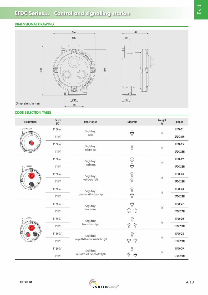
EFDC Series... Control and signalling station
Illustration EntryØD Description Diagram Weight
Kg Codes
1” ISO 7/1Single body:
button 1.4EFDC-21
1” NPT EFDC-21N
1” ISO 7/1Single body:indicator light 1.4
EFDC-25
1” NPT EFDC-25N
1” ISO 7/1Single body:two buttons 1.5
EFDC-22
1” NPT EFDC-22N
1” ISO 7/1Single body:
two indicator lights 1.5EFDC-24
1” NPT EFDC-24N
1” ISO 7/1Single body:
pushbutton with indicator light 1.5EFDC-23
1” NPT EFDC-23N
1” ISO 7/1Single body:three buttons 1.6
EFDC-27
1” NPT EFDC-27N
1” ISO 7/1Single body:
three indicator lights 1.6EFDC-20
1” NPT EFDC-20N
1” ISO 7/1Single body:
two pushbuttons and an indicator light 1.6EFDC-28
1” NPT EFDC-28N
1” ISO 7/1 Single body:
pushbutton with two indicator lights 1.6EFDC-29
1” NPT EFDC-29N
CODE SELECTION TABLE
DIMENSIONAL DRAWING
Dimensions in mm

Ex d
ED.2018A.11
EFDC Series... Control and signalling station
Illustration EntryØD Description Diagram Weight
Kg Codes
1” ISO 7/1Single body:
four pushbuttons 1.8
EFDC-30
1” NPT EFDC-30N
1” ISO 7/1Single body:
four indicator lights 1.8
EFDC-31
1” NPT EFDC-31N
1” ISO 7/1Single body:
three pushbuttons with an indicator light 1.8
EFDC-32
1” NPT EFDC-32N
1” ISO 7/1Single body:
two pushbuttons with two indicator lights 1.8
EFDC-33
1” NPT EFDC-33N
1” ISO 7/1Single body:
pushbutton with three indicator lights 1.8
EFDC-34
1” NPT EFDC-34N
1” ISO 7/1Single body:
emergency pushbutton station with protective glass and hammer
1.4
EFDC-21EMV
1” NPT EFDC-21EMVN
1” ISO 7/1
Single body:emergency pushbutton station 1.4
EFDC-21EM
1” NPT EFDC-21EMN
1” ISO 7/1
Emergency pushbutton station with ‘twist to release’ mushroom head pushbutton 1.4
EFDC-21EMR
1” NPT EDFC-21EMRN
1” ISO 7/1Emergency pushbutton station with key release mushroom head pushbutton (when the button is
pressed, turn the key to release)1.4
EFDC-21EMC
1” NPT EFDC-21EMCN
CODE SELECTION TABLE
Ex d
ED.2018 A.12
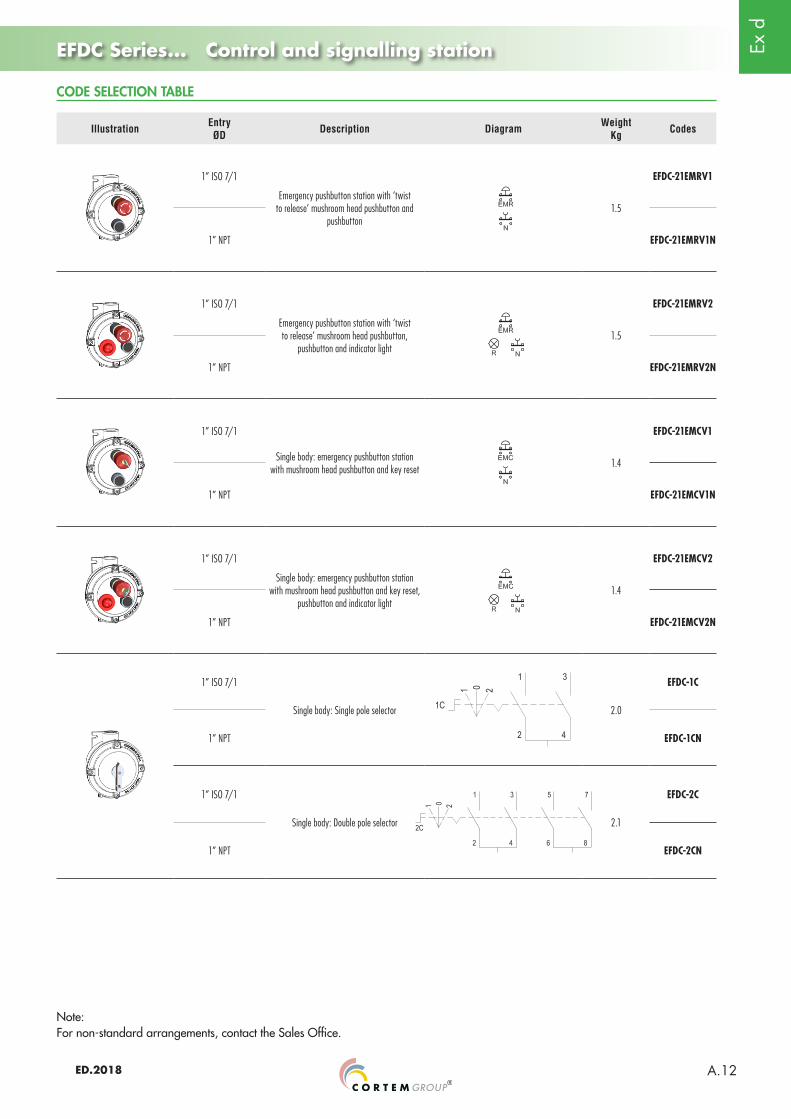
EFDC Series... Control and signalling station
Illustration EntryØD Description Diagram Weight
Kg Codes
1” ISO 7/1
Emergency pushbutton station with ‘twist to release’ mushroom head pushbutton and
pushbutton1.5
EFDC-21EMRV1
1” NPT EFDC-21EMRV1N
1” ISO 7/1
Emergency pushbutton station with ‘twist to release’ mushroom head pushbutton,
pushbutton and indicator light1.5
EFDC-21EMRV2
1” NPT EFDC-21EMRV2N
1” ISO 7/1
Single body: emergency pushbutton station with mushroom head pushbutton and key reset 1.4
EFDC-21EMCV1
1” NPT EFDC-21EMCV1N
1” ISO 7/1
Single body: emergency pushbutton station with mushroom head pushbutton and key reset,
pushbutton and indicator light1.4
EFDC-21EMCV2
1” NPT EFDC-21EMCV2N
1” ISO 7/1
Single body: Single pole selector 2.0
EFDC-1C
1” NPT EFDC-1CN
1” ISO 7/1
Single body: Double pole selector 2.1
EFDC-2C
1” NPT EFDC-2CN
CODE SELECTION TABLE
Note:For non-standard arrangements, contact the Sales Office.

Ex d
ED.2018A.13
EFDC Series... Control and signalling station (Double body)
Dimensions in mm
EFDC33/2C connected to an instrument casing CSC-H with ammeter.
CODE SELECTION TABLE
DESCRIPTION
EFDC series control and signalling stations -.../... are double bodied enclosures and can contain up to eight devices. They are used for the remote control of devices such as distribution panels for lights, pumps, starter motors, etc.
Use the code in the selection table of EFDC single body stations to compose the code for double body stations.
Example:EFDC-20/22 Double body station with three indicator lights in the left-hand enclosure and two pushbuttons in the one to the right. Two 1” ISO7/1 fittings.
EFDC-23/21N Double body station with pushbutton and indicator light in the left-hand enclosure and a pushbutton in the one to the right. Two 1” NPT fittings.
EFDC - N: NPT/
DIMENSIONAL DRAWING
Ex d
ED.2018 A.14
Ex d
ED.2018A.15
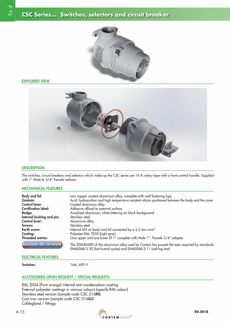
CSC Series... Switches, selectors and circuit breaker
EXPLODED VIEW
MECHANICAL FEATURES
Body and lid: Low copper content aluminium alloy, complete with wall fastening lugs. Gaskets: Acid, hydrocarbon and high temperature resistant silicon positioned between the body and the cover Control lever: Coated aluminium alloyCertification label: Adhesive affixed to external surfaceBadge: Anodised aluminium, white lettering on black backgroundInternal bushing and pin: Stainless steelControl lever: Aluminium alloyScrews: Stainless steelEarth screw: Internal M5 on body and lid connected by a 2.5 mm wire2
Coating: Polyester RAL 7035 (Light grey)Threaded entries: One upper and one lower Ø 1” complete with Male 1”- Female 3/4” adapter
: The STANDARD of the aluminium alloy used by Cortem has passed the tests required by standards EN60068-2-30 (hot-humid cycles) and EN60068-2-11 (salt fog test)
RAL 2004 (Pure orange) internal anti-condensation coatingExternal polyester coatings in various colours (specify RAL colour)Stainless steel version (sample code CSC-216IN)Cast iron version (sample code CSC-216GJ)Cablegland / fittings
ACCESSORIES UPON REQUEST / SPECIAL REQUESTS
DESCRIPTION
The switches, circuit breakers and selectors which make up the CSC series are 16 A rotary type with a front control handle. Supplied with 1” Male to 3/4” Female reducer
Switches: 16A, 690 V
ELECTRICAL FEATURES
Ex d
ED.2018 A.16
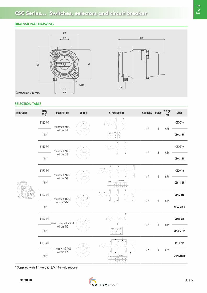
Dimensions in mm
CSC Series... Switches, selectors and circuit breaker
DIMENSIONAL DRAWING
SELECTION TABLE
Illustration EntryØD (*) Description Badge Arrangement Capacity Poles Weight
Kg Code
1” ISO 7/1
Switch with 2 fixed positions ‘0-1’
16 A 2 0.95
CSC-216
1” NPT CSC-216N
1” ISO 7/1
Switch with 2 fixed positions ‘0-1’ 16 A 3 0.86
CSC-316
1” NPT CSC-316N
1” ISO 7/1
Switch with 2 fixed positions ‘0-1’ 16 A 4 0.85
CSC-416
1” NPT CSC-416N
1” ISO 7/1
Switch with 3 fixed positions ‘1-0-2’ 16 A 2 0.89
CSCC-216
1” NPT CSCC-216N
1” ISO 7/1
Circuit breaker with 2 fixed positions ‘1-2’ 16 A 2 0.89
CSCD-216
1” NPT CSCD-216N
1” ISO 7/1
Inverter with 3 fixed positions ‘1-2’ 16 A 2 0.89
CSCI-216
1” NPT CSCI-216N
* Supplied with 1” Male to 3/4” Female reducer
Ex d
ED.2018A.17
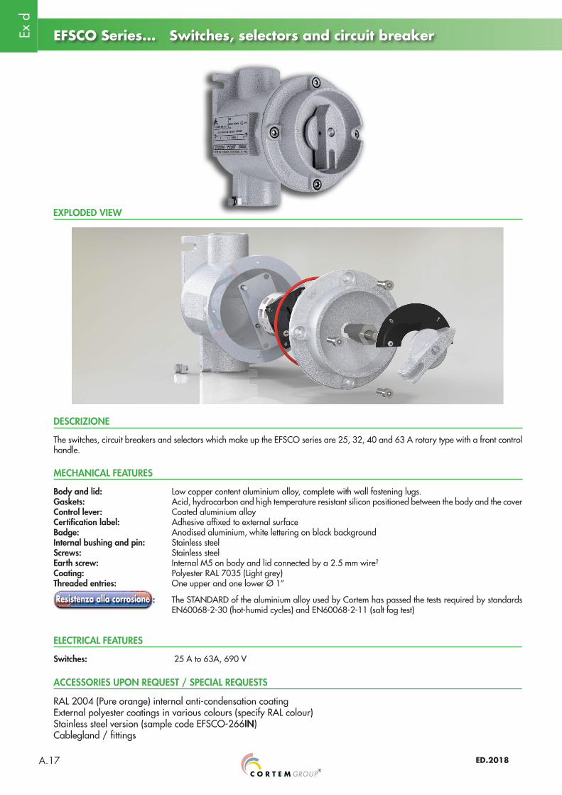
DESCRIZIONE
Body and lid: Low copper content aluminium alloy, complete with wall fastening lugs.Gaskets: Acid, hydrocarbon and high temperature resistant silicon positioned between the body and the cover Control lever: Coated aluminium alloyCertification label: Adhesive affixed to external surfaceBadge: Anodised aluminium, white lettering on black backgroundInternal bushing and pin: Stainless steelScrews: Stainless steelEarth screw: Internal M5 on body and lid connected by a 2.5 mm wire2
Coating: Polyester RAL 7035 (Light grey)Threaded entries: One upper and one lower Ø 1”
: The STANDARD of the aluminium alloy used by Cortem has passed the tests required by standards EN60068-2-30 (hot-humid cycles) and EN60068-2-11 (salt fog test)
EFSCO Series... Switches, selectors and circuit breaker
EXPLODED VIEW
RAL 2004 (Pure orange) internal anti-condensation coatingExternal polyester coatings in various colours (specify RAL colour)Stainless steel version (sample code EFSCO-266IN)Cablegland / fittings
MECHANICAL FEATURES
ACCESSORIES UPON REQUEST / SPECIAL REQUESTS
Switches: 25 A to 63A, 690 V
ELECTRICAL FEATURES
The switches, circuit breakers and selectors which make up the EFSCO series are 25, 32, 40 and 63 A rotary type with a front control handle.
Ex d
ED.2018 A.18
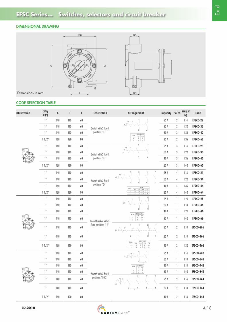
EFSC Series... Switches, selectors and circuit breaker
Dimensions in mm
DIMENSIONAL DRAWING
CODE SELECTION TABLE
Illustration EntryD (*) A G I Description Arrangement Capacity Poles Weight
Kg Code
1” 140 110 60
Switch with 2 fixed positions ‘0-1’
25 A 2 1.14 EFSCO-22
1” 140 110 60 32 A 2 1.20 EFSCO-32
1” 140 110 60 40 A 2 1.35 EFSCO-42
1 1/2” 160 120 80 63 A 2 1.35 EFSCO-62
1” 140 110 60
Switch with 2 fixed positions ‘0-1’
25 A 3 1.14 EFSCO-23
1” 140 110 60 32 A 3 1.20 EFSCO-33
1” 140 110 60 40 A 3 1.35 EFSCO-43
1 1/2” 160 120 80 63 A 3 1.40 EFSCO-63
1” 140 110 60
Switch with 2 fixed positions ‘0-1’
25 A 4 1.18 EFSCO-24
1” 140 110 60 32 A 4 1.20 EFSCO-34
1” 140 110 60 40 A 4 1.35 EFSCO-44
1 1/2” 160 120 80 63 A 4 1.40 EFSCO-64
1” 140 110 60
Circuit breaker with 2 fixed positions ‘1-2’
25 A 1 1.20 EFSCO-26
1” 140 110 60 32 A 1 1.18 EFSCO-36
1” 140 110 60 40 A 1 1.20 EFSCO-46
1” 140 110 60 63 A 1 1.40 EFSCO-66
1” 140 110 60 25 A 2 1.18 EFSCO-266
1” 140 110 60 32 A 2 1.18 EFSCO-366
1 1/2” 160 120 80 40 A 2 1.20 EFSCO-466
1” 140 110 60
Switch with 3 fixed positions ‘1-0-2’
25 A 1 1.14 EFSCO-242
1” 140 110 60 32 A 1 1.18 EFSCO-342
1” 140 110 60 40 A 1 1.18 EFSCO-442
1” 140 110 60 63 A 1 1.40 EFSCO-642
1” 140 110 60 25 A 2 1.14 EFSCO-244
1” 140 110 60 32 A 2 1.18 EFSCO-344
1 1/2” 160 120 80 40 A 2 1.18 EFSCO-444
Ex d
ED.2018A.19
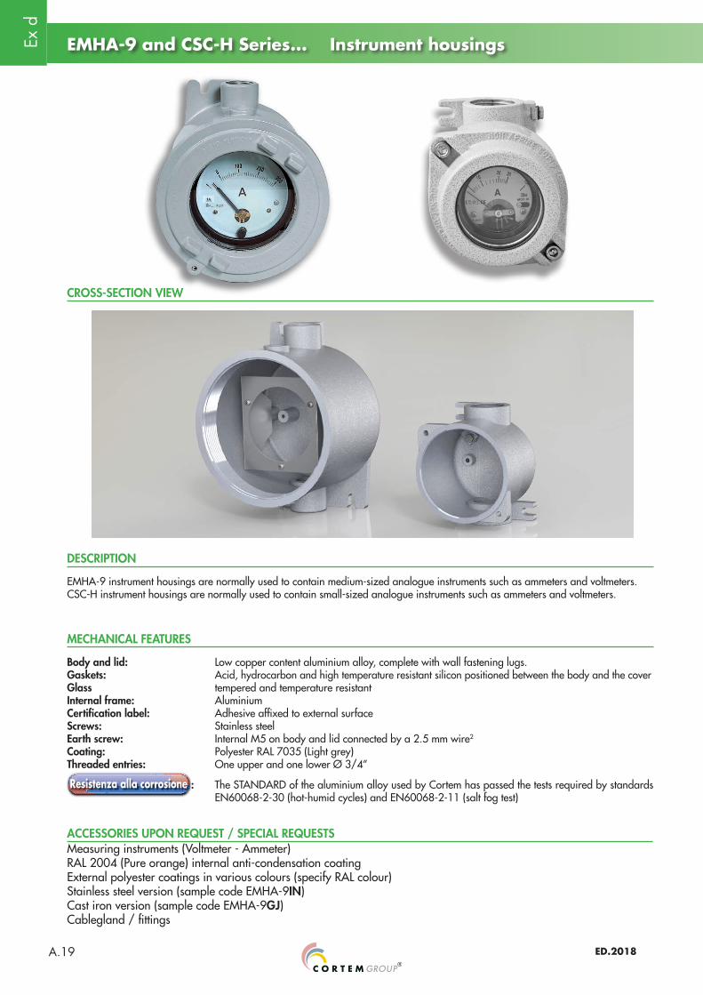
EMHA-9 and CSC-H Series... Instrument housings
CROSS-SECTION VIEW
MECHANICAL FEATURES
Body and lid: Low copper content aluminium alloy, complete with wall fastening lugs.Gaskets: Acid, hydrocarbon and high temperature resistant silicon positioned between the body and the coverGlass tempered and temperature resistantInternal frame: AluminiumCertification label: Adhesive affixed to external surfaceScrews: Stainless steelEarth screw: Internal M5 on body and lid connected by a 2.5 mm wire2
Coating: Polyester RAL 7035 (Light grey)Threaded entries: One upper and one lower Ø 3/4”
: The STANDARD of the aluminium alloy used by Cortem has passed the tests required by standards EN60068-2-30 (hot-humid cycles) and EN60068-2-11 (salt fog test)
Measuring instruments (Voltmeter - Ammeter)RAL 2004 (Pure orange) internal anti-condensation coatingExternal polyester coatings in various colours (specify RAL colour)Stainless steel version (sample code EMHA-9IN)Cast iron version (sample code EMHA-9GJ)Cablegland / fittings
ACCESSORIES UPON REQUEST / SPECIAL REQUESTS
DESCRIPTION
EMHA-9 instrument housings are normally used to contain medium-sized analogue instruments such as ammeters and voltmeters.CSC-H instrument housings are normally used to contain small-sized analogue instruments such as ammeters and voltmeters.

Ex d
ED.2018 A.20
EMHA-9 and CSC-H Series... Instrument housings
Dimensions in mm
DIMENSIONAL DRAWING
Illustration EntryØD Description Weight
Kg Codes
3/4” ISO7/1
Instrument casing Ø85 mm 1.88
EMHA-9
3/4” NPT EMHA-9N
1” ISO 7/1
Single body: instrument casing 0.75
CSC-H
1” NPT CSC-HN
CODE SELECTION TABLE
Ex d
ED.2018A.21
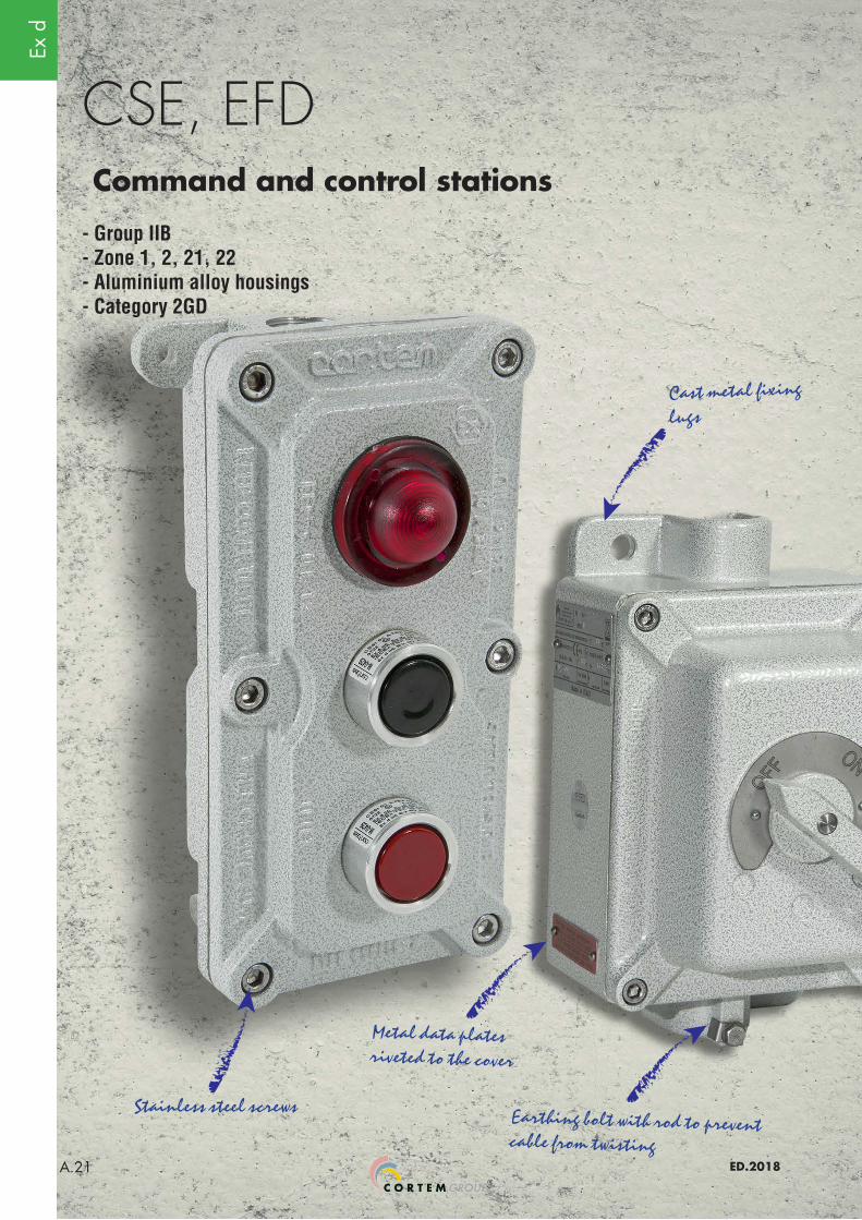
CSE, EFD
Metal data plates riveted to the cover
Stainless steel screws Earthing bolt with rod to prevent cable from twisting
Command and control stations
- Group IIB- Zone 1, 2, 21, 22- Aluminium alloy housings- Category 2GD
Cast metal fixing lugs

Ex d
ED.2018 A.22
CSE Series... Control and signalling station
The Ex d IIB stations and controllers are suitable for the control and signalling of devices installed both “on board” the machine and remotely (P.E on a field control column). They are easily installed using wall mount lugs and have threaded entries for connection by means of a cable gland or metal pipe.Used specifically in offshore and onshore environments, the chemical, petrochemical and pharmaceutical industries, and all locations which require an explosion proof system.
Sectors of application:
EMPTY ENCLOSURE CERTIFICATION DATA
Petroleum refineries
Chemical and petrochemical
plants
Onshore plants
Offshore plants
Petroleum loading/unloading pontoons
Low temperatures
Mining operations
100% produced by
Cortem
Classification: Group II Category 2GD
Installation: EN 60079.14 zone 1 - zone 2 (Gas) zone 21 - zone 22 (Dust)
Marking: II 2 GD; Ex d IIB T6 Gb; Ex tb IIIC T85°C Db
II 2 GD; Ex d IIB T5 Gb; Ex tb IIIC T100°C Db
Certificate: ATEX CESI 03 ATEX 172
TR CU B.02184 For all IEC Ex and TR CU certification data, download the certificate from www.cortemgroup.com
Standards:CENELEC EN 60079-0: 2012, EN 60079-1:2007, EN 60079-31: 2009 and EUROPEAN DIRECTIVE 2014/34/EURoHS Directive 2002/95/EC.
Temperature class: T6 (Ta +40°C) T5 (Ta +55°C)
Temp. Temperature: -20 °C +55 °C
-20 °C +40 °C
Degree of protection: IP66
ATEX Certificate Use and maintenance instructions
A QR reader is required
to access the information
contained in the QRCode.
Centre the QR code in the
frame of your Smartphone camera.
Your Smartphone will open the
corresponding address.
Cortem Group labels its products with a non-removable adhesive label featuring a hologram and an alphanumerical univocal code, as a safety measure against the illegal sale of fakes so that all the products are guaranteed as original. Non-compliance with the International standards entails serious risks for the environment, especially for those working daily on the plants.
Ex d
ED.2018A.23
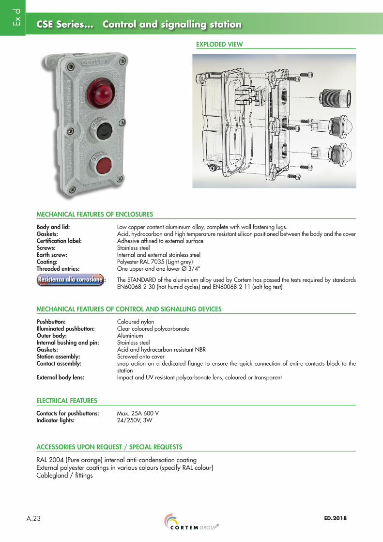
Body and lid: Low copper content aluminium alloy, complete with wall fastening lugs.Gaskets: Acid, hydrocarbon and high temperature resistant silicon positioned between the body and the coverCertification label: Adhesive affixed to external surfaceScrews: Stainless steelEarth screw: Internal and external stainless steelCoating: Polyester RAL 7035 (Light grey)Threaded entries: One upper and one lower Ø 3/4”
: The STANDARD of the aluminium alloy used by Cortem has passed the tests required by standards EN60068-2-30 (hot-humid cycles) and EN60068-2-11 (salt fog test)
CSE Series... Control and signalling station
Pushbutton: Coloured nylonIlluminated pushbutton: Clear coloured polycarbonateOuter body: AluminiumInternal bushing and pin: Stainless steel Gaskets: Acid and hydrocarbon resistant NBRStation assembly: Screwed onto coverContact assembly: snap action on a dedicated flange to ensure the quick connection of entire contacts block to the
stationExternal body lens: Impact and UV resistant polycarbonate lens, coloured or transparent
MECHANICAL FEATURES OF ENCLOSURES
MECHANICAL FEATURES OF CONTROL AND SIGNALLING DEVICES
RAL 2004 (Pure orange) internal anti-condensation coatingExternal polyester coatings in various colours (specify RAL colour)Cablegland / fittings
ACCESSORIES UPON REQUEST / SPECIAL REQUESTS
EXPLODED VIEW
Contacts for pushbuttons: Max. 25A 600 VIndicator lights: 24/250V, 3W
ELECTRICAL FEATURES
Ex d
ED.2018 A.24
CSE Series... Control and signalling station
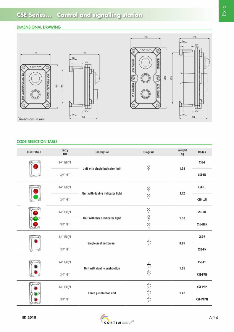
Dimensions in mm
DIMENSIONAL DRAWING
Illustration EntryØD Description Diagram Weight
Kg Codes
3/4” ISO7/1
Unit with single indicator light 1.01
CSE-L
3/4” NPT CSE-LN
3/4” ISO7/1
Unit with double indicator light 1.12
CSE-LL
3/4” NPT CSE-LLN
3/4” ISO7/1
Unit with three indicator light 1.53
CSE-LLL
3/4” NPT CSE-LLLN
3/4” ISO7/1
Single pushbutton unit 0.97
CSE-P
3/4” NPT CSE-PN
3/4” ISO7/1
Unit with double pushbutton 1.05
CSE-PP
3/4” NPT CSE-PPN
3/4” ISO7/1
Three pushbutton unit 1.42
CSE-PPP
3/4” NPT CSE-PPPN
CODE SELECTION TABLE
Ex d
ED.2018A.25
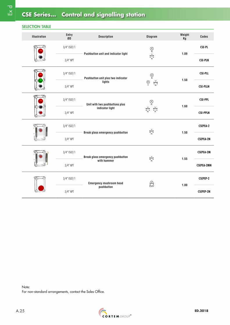
SELECTION TABLE
CSE Series... Control and signalling station
Illustration EntryØD Description Diagram Weight
Kg Codes
3/4” ISO7/1
Pushbutton unit and indicator light 1.09
CSE-PL
3/4” NPT CSE-PLN
3/4” ISO7/1Pushbutton unit plus two indicator
lights 1.50
CSE-PLL
3/4” NPT CSE-PLLN
3/4” ISO7/1Unit with two pushbuttons plus
indicator light 1.60
CSE-PPL
3/4” NPT CSE-PPLN
3/4” ISO7/1
Break glass emergency pushbutton 1.50
CSEPEA-2
3/4” NPT CSEPEA-2N
3/4” ISO7/1Break glass emergency pushbutton
with hammer 1.55
CSEPEA-2M
3/4” NPT CSEPEA-2MN
3/4” ISO7/1Emergency mushroom head
pushbutton 1.00
CSEPEP-2
3/4” NPT CSEPEP-2N
Note:For non-standard arrangements, contact the Sales Office.
Ex d
ED.2018 A.26
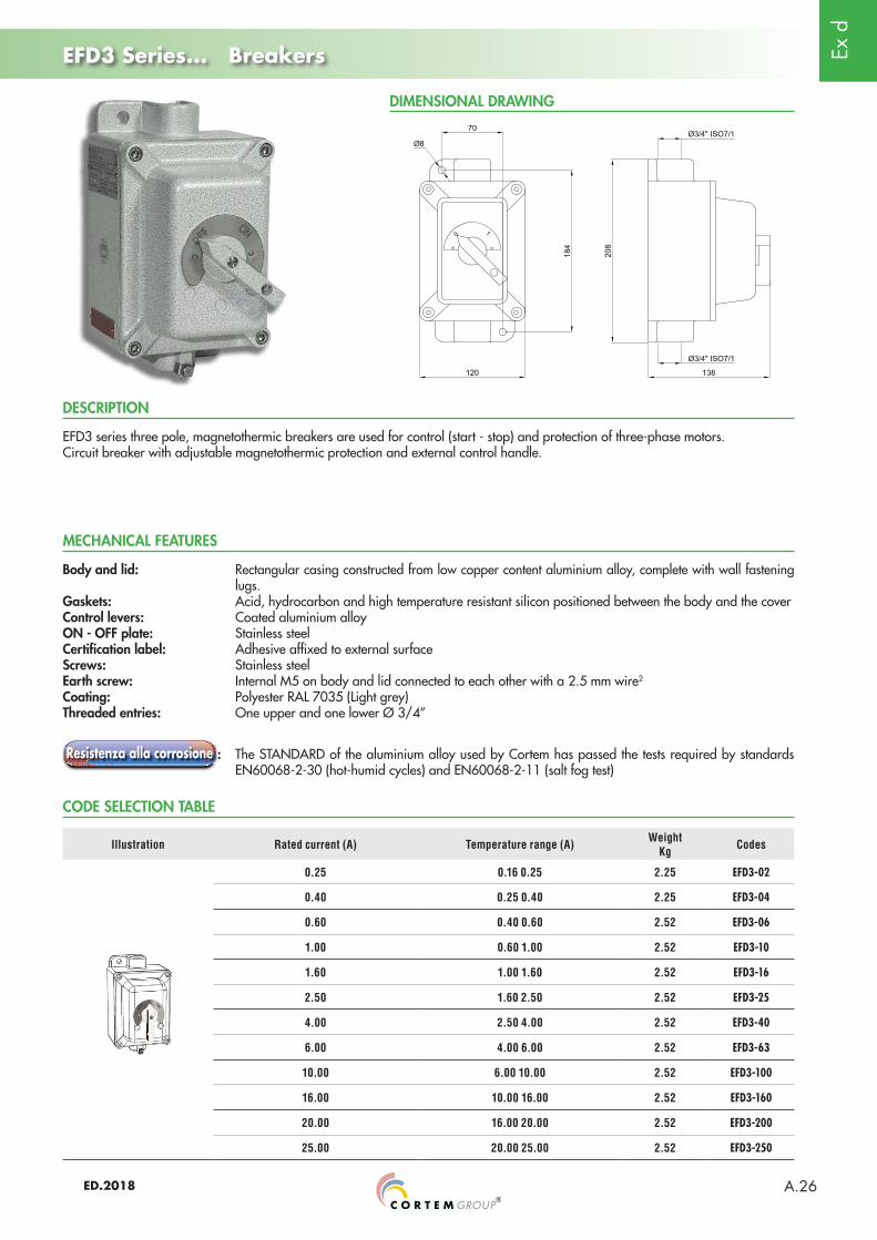
EFD3 Series... Breakers
DIMENSIONAL DRAWING
Body and lid: Rectangular casing constructed from low copper content aluminium alloy, complete with wall fastening lugs.
Gaskets: Acid, hydrocarbon and high temperature resistant silicon positioned between the body and the coverControl levers: Coated aluminium alloyON - OFF plate: Stainless steelCertification label: Adhesive affixed to external surfaceScrews: Stainless steelEarth screw: Internal M5 on body and lid connected to each other with a 2.5 mm wire2
Coating: Polyester RAL 7035 (Light grey)Threaded entries: One upper and one lower Ø 3/4”
: The STANDARD of the aluminium alloy used by Cortem has passed the tests required by standards EN60068-2-30 (hot-humid cycles) and EN60068-2-11 (salt fog test)
EFD3 series three pole, magnetothermic breakers are used for control (start - stop) and protection of three-phase motors. Circuit breaker with adjustable magnetothermic protection and external control handle.
MECHANICAL FEATURES
DESCRIPTION
CODE SELECTION TABLE
Illustration Rated current (A) Temperature range (A) Weight Kg Codes
0.25 0.16 0.25 2.25 EFD3-02
0.40 0.25 0.40 2.25 EFD3-04
0.60 0.40 0.60 2.52 EFD3-06
1.00 0.60 1.00 2.52 EFD3-10
1.60 1.00 1.60 2.52 EFD3-16
2.50 1.60 2.50 2.52 EFD3-25
4.00 2.50 4.00 2.52 EFD3-40
6.00 4.00 6.00 2.52 EFD3-63
10.00 6.00 10.00 2.52 EFD3-100
16.00 10.00 16.00 2.52 EFD3-160
20.00 16.00 20.00 2.52 EFD3-200
25.00 20.00 25.00 2.52 EFD3-250
Ex d
ED.2018A.27
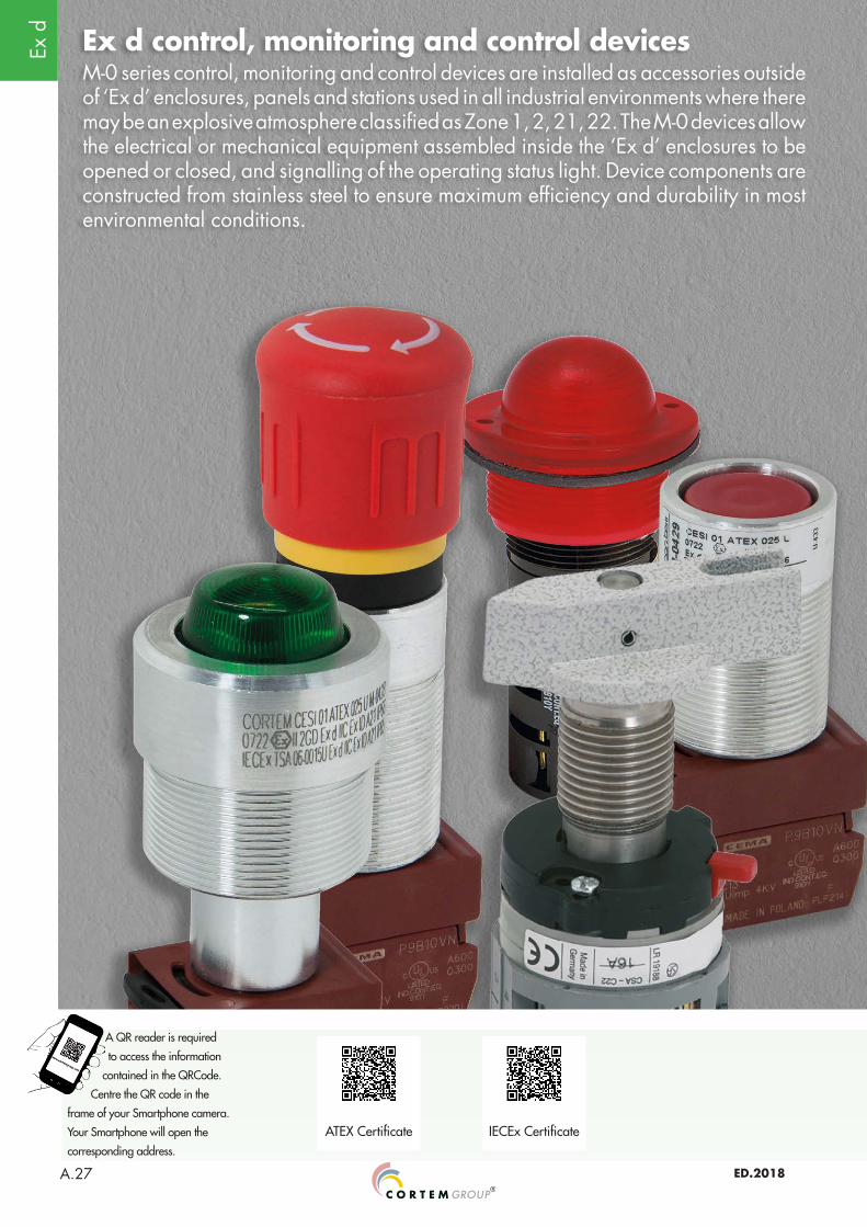
Ex d control, monitoring and control devicesM-0 series control, monitoring and control devices are installed as accessories outside of ‘Ex d’ enclosures, panels and stations used in all industrial environments where there may be an explosive atmosphere classified as Zone 1, 2, 21, 22. The M-0 devices allow the electrical or mechanical equipment assembled inside the ‘Ex d’ enclosures to be opened or closed, and signalling of the operating status light. Device components are constructed from stainless steel to ensure maximum efficiency and durability in most environmental conditions.
ATEX Certificate IECEx Certificate
A QR reader is required
to access the information
contained in the QRCode.
Centre the QR code in the
frame of your Smartphone camera.
Your Smartphone will open the
corresponding address.
Ex d
ED.2018 A.28
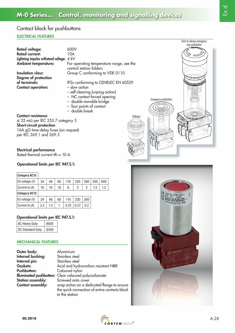
M-0 Series... Control, monitoring and signalling devices
ELECTRICAL FEATURES
MECHANICAL FEATURES
Rated voltage: 600VRated current: 10ALightning impulse withstand voltage: 4 kVAmbient temperature: For operating temperature range, see the control station foldersInsulation class: Group C conforming to VDE 0110Degree of protection of terminals: IP2x conforming to CENELEC EN 60529Contact operation: – slow action – self-cleaning (wiping action) – NC contact forced opening – double movable bridge – four points of contact – double breakContact resistance≤ 25 mΩ per IEC 255.7 category 3Short-circuit protection 16A gG time-delay fuses (on request) per IEC 269.1 and 269.3
Category AC15
EU voltage (V) 24 48 60 110 220 380 500 600
Current Ie (A) 10 10 10 6 3 2 1.5 1.2
Category DC13
EU voltage (V) 24 48 60 110 220 300
Current Ie (A) 2.5 1.5 1 0.22 0.27 0.2
Electrical performanceRated thermal current Ith = 10 A
Operational limits per IEC 947.5.1:
Operational limits per IEC 947.5.1:AC Heavy Duty A600
DC Standard Duty Q300
Outer body: AluminiumInternal bushing: Stainless steel Internal pin: Stainless steelGaskets: Acid and hydrocarbon resistant NBRPushbutton: Coloured nylonIlluminated pushbutton: Clear coloured polycarbonateStation assembly: Screwed onto coverContact assembly: snap action on a dedicated flange to ensure
the quick connection of entire contacts block to the station
Pollution
Emergency pushbutton
Twist to release emergency stop pushbutton
Contact block for pushbuttons
Ex d
ED.2018A.29
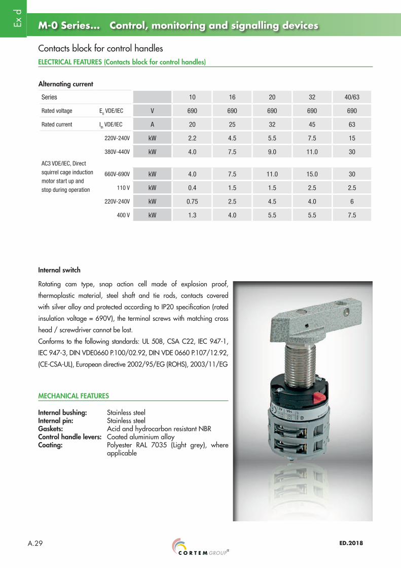
M-0 Series... Control, monitoring and signalling devices
MECHANICAL FEATURES
ELECTRICAL FEATURES (Contacts block for control handles)
Series 10 16 20 32 40/63
Rated voltage EU VDE/IEC V 690 690 690 690 690
Rated current Ith VDE/IEC A 20 25 32 45 63
AC3 VDE/IEC, Direct
squirrel cage induction
motor start up and
stop during operation
220V-240V kW 2.2 4.5 5.5 7.5 15
380V-440V kW 4.0 7.5 9.0 11.0 30
660V-690V kW 4.0 7.5 11.0 15.0 30
110 V kW 0.4 1.5 1.5 2.5 2.5
220V-240V kW 0.75 2.5 4.5 4.0 6
400 V kW 1.3 4.0 5.5 5.5 7.5
Alternating current
Internal switch
Rotating cam type, snap action cell made of explosion proof,
thermoplastic material, steel shaft and tie rods, contacts covered
with silver alloy and protected according to IP20 specification (rated
insulation voltage = 690V), the terminal screws with matching cross
head / screwdriver cannot be lost.
Conforms to the following standards: UL 508, CSA C22, IEC 947-1,
IEC 947-3, DIN VDE0660 P.100/02.92, DIN VDE 0660 P.107/12.92,
(CE-CSA-UL), European directive 2002/95/EG (ROHS), 2003/11/EG
Internal bushing: Stainless steel Internal pin: Stainless steelGaskets: Acid and hydrocarbon resistant NBRControl handle levers: Coated aluminium alloyCoating: Polyester RAL 7035 (Light grey), where
applicable
Contacts block for control handles
Ex d
ED.2018 A.30
Padlocking option
M-0 Series... Control, monitoring and signalling devices
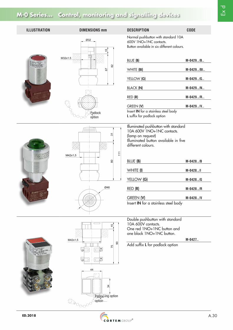
ILLUSTRATION DIMENSIONS mm DESCRIPTION CODE
Normal pushbutton with standard 10A 600V 1NO+1NC contacts. Button available in six different colours.
BLUE (B) M-0429../B..
WHITE (BI) M-0429../BI..
YELLOW (G) M-0429../G..
BLACK (N) M-0429../N..
RED (R) M-0429../R..
GREEN (V) M-0429../V..Insert IN for a stainless steel bodyL suffix for padlock option
Illuminated pushbutton with standard 10A 600V 1NO+1NC contacts. (lamp on request) Illuminated button available in five different colours.
BLUE (B) M-0428../B
WHITE (I) M-0428../I
YELLOW (G) M-0428../G
RED (R) M-0428../R
GREEN (V) M-0428../VInsert IN for a stainless steel body
Double pushbutton with standard 10A 600V contacts. One red 1NO+1NC button and one black 1NO+1NC button.
M-0427..Add suffix L for padlock option
Padlok option
Padlock option
Ex d
ED.2018A.31
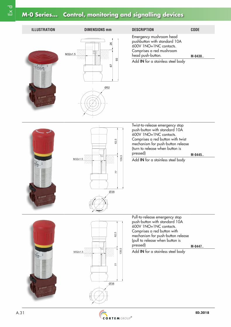
M-0 Series... Control, monitoring and signalling devices
ILLUSTRATION DIMENSIONS mm DESCRIPTION CODE
Emergency mushroom head pushbutton with standard 10A 600V 1NO+1NC contacts. Comprises a red mushroom head push-button. M-0430..Add IN for a stainless steel body
Twist-to-release emergency stop push-button with standard 10A 600V 1NO+1NC contacts. Comprises a red button with twist mechanism for push-button release (turn to release when button is pressed) M-0445..Add IN for a stainless steel body
Pull-to-release emergency stop push-button with standard 10A 600V 1NO+1NC contacts. Comprises a red button with mechanism for push-button release (pull to release when button is pressed) M-0447..Add IN for a stainless steel body
Ex d
ED.2018 A.32
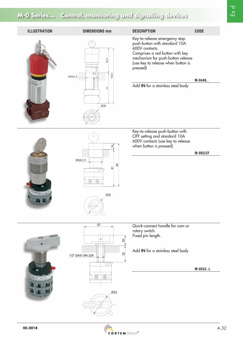
M-0 Series... Control, monitoring and signalling devices
ILLUSTRATION DIMENSIONS mm DESCRIPTION CODE
Key-to-release emergency stop push-button with standard 10A 600V contacts. Comprises a red button with key mechanism for push-button release (use key to release when button is pressed)
M-0446..Add IN for a stainless steel body
Key-to-release push-button with OFF setting and standard 10A 600V contacts (use key to release when button is pressed)
M-093/CF
Quick-connect handle for cam or rotary switch. Fixed pin length.
Add IN for a stainless steel body
M-0553..L
Ex d
ED.2018A.33
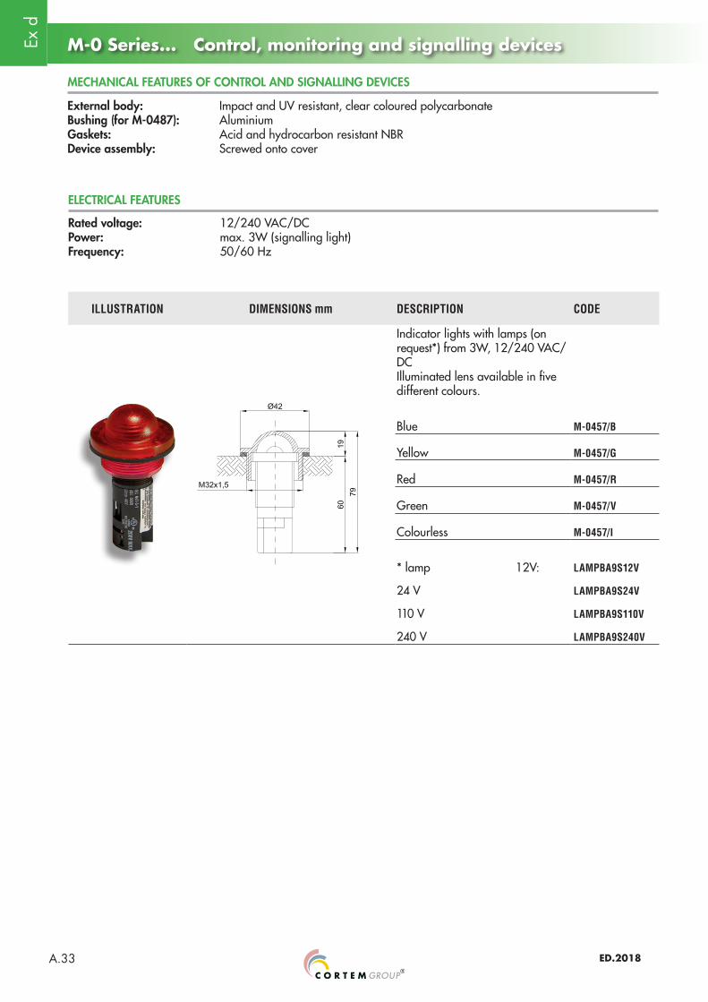
M-0 Series... Control, monitoring and signalling devices
External body: Impact and UV resistant, clear coloured polycarbonateBushing (for M-0487): Aluminium Gaskets: Acid and hydrocarbon resistant NBRDevice assembly: Screwed onto cover
MECHANICAL FEATURES OF CONTROL AND SIGNALLING DEVICES
ELECTRICAL FEATURES
Rated voltage: 12/240 VAC/DCPower: max. 3W (signalling light)Frequency: 50/60 Hz
ILLUSTRATION DIMENSIONS mm DESCRIPTION CODE
Indicator lights with lamps (on request*) from 3W, 12/240 VAC/DCIlluminated lens available in five different colours.
Blue M-0457/B
Yellow M-0457/G
Red M-0457/R
Green M-0457/V
Colourless M-0457/I
* lamp 12V: LAMPBA9S12V
24 V LAMPBA9S24V
110 V LAMPBA9S110V
240 V LAMPBA9S240V
Ex d
ED.2018 A.34