ex 2 way installation
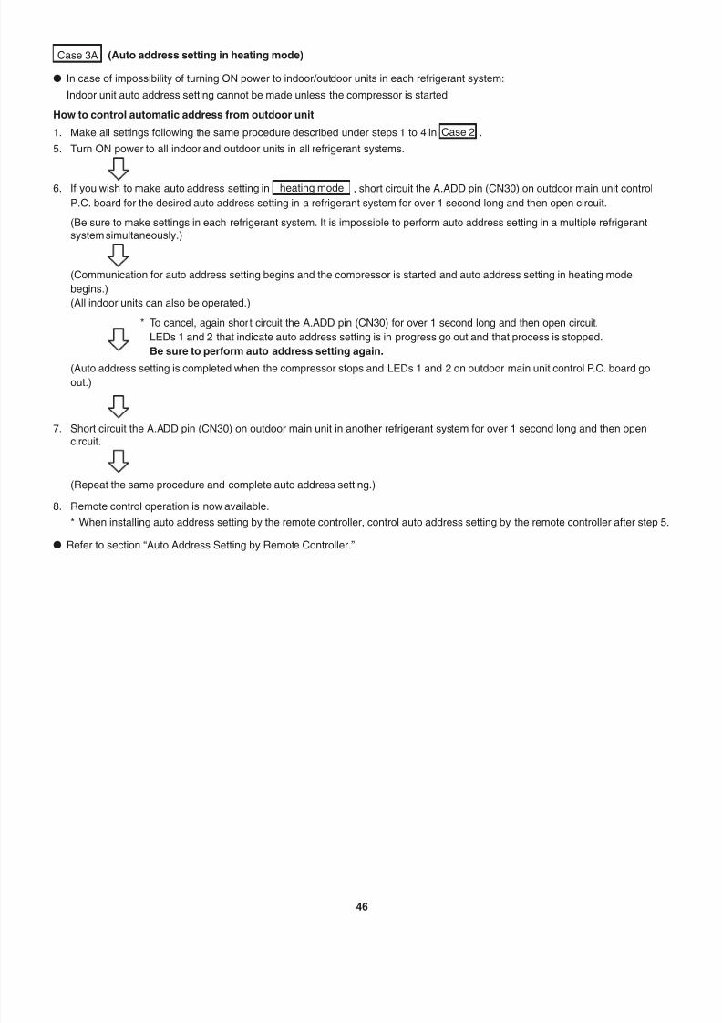
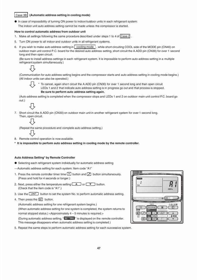
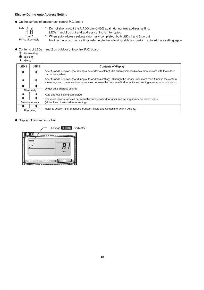
TRANSCRIPT

7/25/2019 Ex 2 Way Installation
http://slidepdf.com/reader/full/ex-2-way-installation 1/57
INSTALLATION INSTRUCTIONS
2WAY VRF System Air Conditioner
85464369760021-SP
Table 1-7 Indoor Unit Tubing Connection Size Unit: in. (mm)
Indoor unit type 7 9 12 15 18 19 24 36 48 54
Gas tubing ø1/2" (ø12.7) ø5/8" (ø15.88)
Liquid tubing ø1/4" (ø6.35) ø3/8" (ø9.52)
Necessary Amount of Additional Refrigerant Charge for All Indoor Unit Cooling Capacity
Charge a refrigerant amount calculated in the following formula according to the total amount of indoor unit cooling capacity.
Additional refrigerant amount when cooling capacity is BTU/h = Cooling capacity (BTU/h) x 1.034 x 0.001 + 10.6 (oz)
or Additional refrigerant amount when cooling capacity is kW = Cooling capacity (kW) x 1000 x 0.1 + 300 (g)
Regarding the system connected to the indoor unit model S-19MS1U6, see the following contents.
1. Additional sentences are provided in the "NOTE" under the section "Table 1-2 Ranges that Apply to Refrigerant Tubing Lengths
and to Differences in Installation Heights " on page 8 in the Installation Instructions.
7: If the tubing length which is connected to the model S-19MS1U6 is less than 8 m (26.2 ft) between the outdoor unit and
the final distribution joint, increase the size of the gas tube between them by one-rank-higher.
* When connecting the gas tube for S-19MS1U6, use a field supply reducer.
3. Replace the section "Necessary Amount of Additional Refrigerant Charge for All Indoor Unit Cooling Capacity" on page 10 in the
Installation Instructions with the following table.
* However, calculate the cooling capacity of the indoor unit S-19MS1U6 as 0 kW.
SUPPLEMENT
2. Replace the section "Table 1-7 Indoor Unit Tubing Connection Size" on page 9 in the Installation Instructions with the following table
7/25/2019 Ex 2 Way Installation
http://slidepdf.com/reader/full/ex-2-way-installation 2/57
INSTALLATION INSTRUCTIONS
2WAY VRF System Air Conditioner
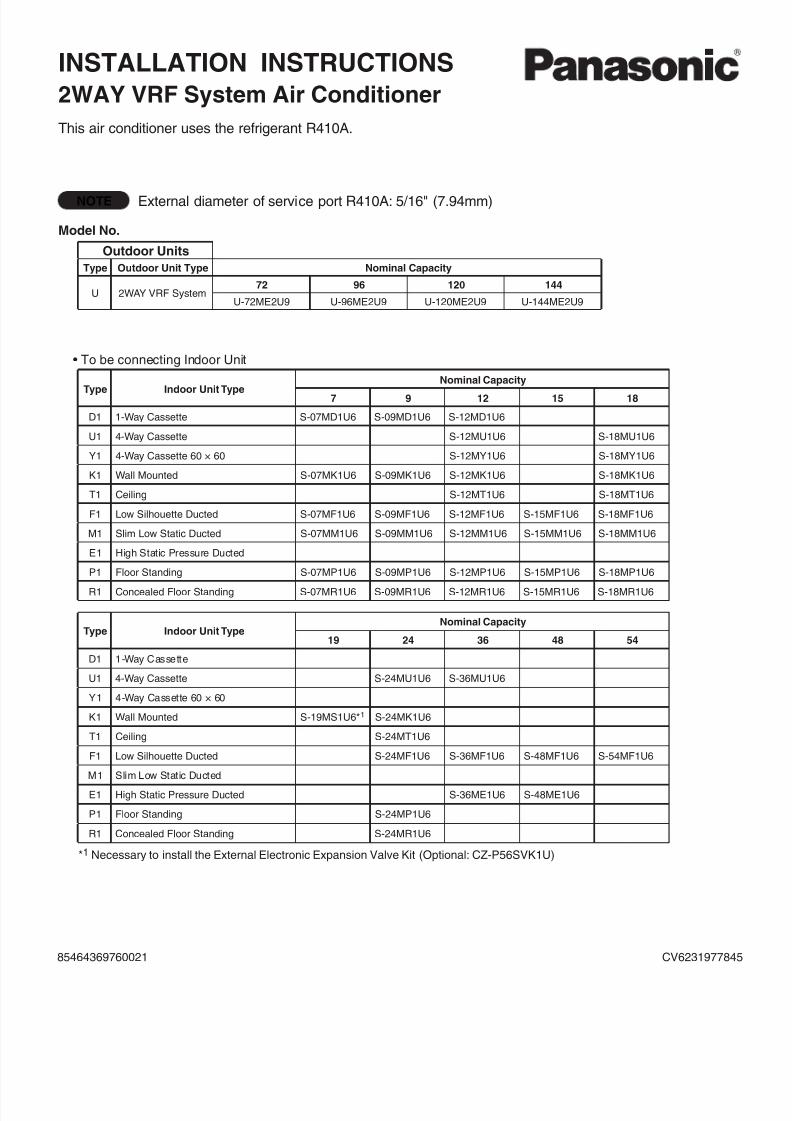
This air conditioner uses the refrigerant R410A.
NOTE External diameter of service port R410A: 5/16" (7.94mm)
Model No.
Outdoor Units
Type Outdoor Unit Type Nominal Capacity
U 2WAY VRF System72 96 120 144
U-72ME2U9 U-96ME2U9 U-120ME2U9 U-144ME2U9
• To be connecting Indoor Unit
Type Indoor Unit Type
Nominal Capacity
7 9 12 15 18
D1 1-Way Cassette S-07MD1U6 S-09MD1U6 S-12MD1U6
U1 4-Way Cassette S-12MU1U6 S-18MU1U6
Y1 4-Way Cassette 60 × 60 S-12MY1U6 S-18MY1U6
K1 Wall Mounted S-07MK1U6 S-09MK1U6 S-12MK1U6 S-18MK1U6
T1 Ceiling S-12MT1U6 S-18MT1U6
F1 Low Silhouette Ducted S-07MF1U6 S-09MF1U6 S-12MF1U6 S-15MF1U6 S-18MF1U6
M1 Slim Low Static Ducted S-07MM1U6 S-09MM1U6 S-12MM1U6 S-15MM1U6 S-18MM1U6
E1 High Static Pressure Ducted
P1 Floor Standing S-07MP1U6 S-09MP1U6 S-12MP1U6 S-15MP1U6 S-18MP1U6
R1 Concealed Floor Standing S-07MR1U6 S-09MR1U6 S-12MR1U6 S-15MR1U6 S-18MR1U6
Type Indoor Unit TypeNominal Capacity
19 24 36 48 54
D1 1-Way Cassette
U1 4-Way Cassette S-24MU1U6 S-36MU1U6
Y1 4-Way Cassette 60 × 60
K1 Wall Mounted S-19MS1U6*1 S-24MK1U6
T1 Ceiling S-24MT1U6
F1 Low Silhouette Ducted S-24MF1U6 S-36MF1U6 S-48MF1U6 S-54MF1U6
M1 Slim Low Static Ducted
E1 High Static Pressure Ducted S-36ME1U6 S-48ME1U6
P1 Floor Standing S-24MP1U6
R1 Concealed Floor Standing S-24MR1U6
*1 Necessary to install the External Electronic Expansion Valve Kit (Optional: CZ-P56SVK1U)
85464369760021 CV6231977845

7/25/2019 Ex 2 Way Installation
http://slidepdf.com/reader/full/ex-2-way-installation 3/572
This air conditioning system meets strict safety andoperating standards. As the installer or service person, it isan important part of your job to install or service the system
so it operates safely and efficiently.
For safe installation and trouble-free operation, you must:
Carefully read this instruction booklet before beginning.Follow each installation or repair step exactly as shown.
Observe all local, state, and national electrical codes.
Pay close attention to all warning and caution noticesgiven in this manual.
CAUTION
WARNING
This symbol refers to a hazard orunsafe practice which can resultin severe personal injury or death.
This symbol refers to a hazard orunsafe practice which can resultin personal injury or product orproperty damage.
If Necessary, Get HelpThese instructions are all you need for most installationsites and maintenance conditions. If you require help for a
special problem, contact our sales/service outlet or your
certified dealer for additional instructions.
In Case of Improper InstallationThe manufacturer shall in no way be responsible for
improper installation or maintenance service, includingfailure to follow the instructions in this document.
SPECIAL PRECAUTIONS
WARNING When WiringELECTRICAL SHOCK CAN CAUSE
SEVERE PERSONAL INJURY OR DEATH.
ONLY A QUALIFIED, EXPERIENCED
ELECTRICIAN SHOULD ATTEMPT TO
WIRE THIS SYSTEM.
• Do not supply power to the unit until all wiring and tubingare completed or reconnected and checked.
• Highly dangerous electrical voltages are used in thissystem. Carefully refer to the wiring diagram and theseinstructions when wiring. Improper connections andinadequate grounding can cause accidental injury or
death.• Ground the unit following local electrical codes.
• Connect all wiring tightly. Loose wiring may causeoverheating at connection points and a possible fire hazard.
• To prevent possible hazards from insulation failure,the unit must be grounded.
• This equipment is strongly recommended to be installedwith Earth Leakage Circuit Breaker (ELCB) or ResidualCurrent Device (RCD). Otherwise, it may cause electricalshock and fire in case of equipment breakdown orinsulation breakdown.
When Transporting
Be careful when picking up and moving the indoor and
outdoor units. Get a partner to help, and bend your knees
when lifting to reduce strain on your back. Sharp edges orthin aluminum fins on the air conditioner can cut your fingers.
When Installing…
Select an installation location which is rigid and strongenough to support or hold the unit, and select a location foreasy maintenance.
…In a Room
Properly insulate any tubing run inside a room to prevent“sweating” that can cause dripping and water damage towalls and floors.
CAUTIONKeep the fire alarm and the air outlet at
least 5 feet (1.5m) away from the unit.
…In Moist or Uneven Locations
Use a raised concrete pad or concrete blocks to providea solid, level foundation for the outdoor unit. This preventswater damage and abnormal vibration.
…In an Area with High Winds
Securely anchor the outdoor unit down with bolts and ametal frame. Provide a suitable air baffle.
…In a Snowy Area (for Heat Pump-type Systems)
Install the outdoor unit on a raised platform that is higherthan drifting snow. Provide snow vents.
When Connecting Refrigerant Tubing
• Ventilate the room well, in the event that is refrigerant
gas leaks during the installation. Be careful not to allowcontact of the refrigerant gas with a flame as this willcause the generation of poisonous gas.
• Keep all tubing runs as short as possible.
• Use the flare method for connecting tubing.
• Apply refrigerant lubricant to the matching surfaces of theflare and union tubes before connecting them, then tightenthe nut with a torque wrench for a leak-free connection.
• Check carefully for leaks before starting the test run.
WARNING
• When performing piping work do notmix air except for specified refrigerant(R410A) in refrigeration cycle. It causes
capacity down, and risk of explosionand injury due to high tension insidethe refrigerant cycle.
• Check for a leaking refrigerant!Refrigerant gas may produce a toxicgas if it comes in contact with fire.
• Do not add or replace refrigerant otherthan specified type.It may cause product damage, burstand injury etc.
• Do not leak refrigerant while piping work for an installationor re-installation, and while repairing refrigeration parts.Handle liquid refrigerant carefully as it may cause frostbite.
IMPORTANT!Please Read Before Starting
7/25/2019 Ex 2 Way Installation
http://slidepdf.com/reader/full/ex-2-way-installation 4/573
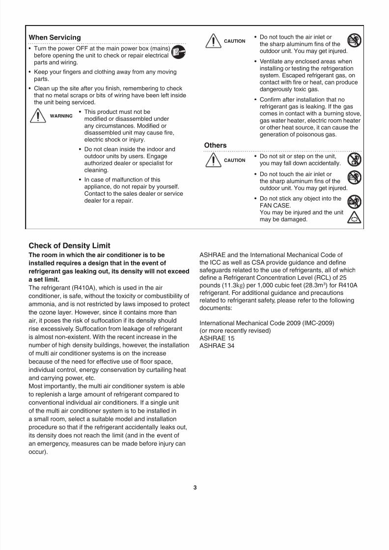
When Servicing
• Turn the power OFF at the main power box (mains)before opening the unit to check or repair electricalparts and wiring.
• Keep your fingers and clothing away from any movingparts.
• Clean up the site after you finish, remembering to check
that no metal scraps or bits of wiring have been left insidethe unit being serviced.
WARNING• This product must not be
modified or disassembled underany circumstances. Modified ordisassembled unit may cause fire,electric shock or injury.
• Do not clean inside the indoor andoutdoor units by users. Engageauthorized dealer or specialist forcleaning.
• In case of malfunction of thisappliance, do not repair by yourself.
Contact to the sales dealer or servicedealer for a repair.
CAUTION• Do not touch the air inlet or
the sharp aluminum fins of theoutdoor unit. You may get injured.
• Ventilate any enclosed areas wheninstalling or testing the refrigerationsystem. Escaped refrigerant gas, oncontact with fire or heat, can producedangerously toxic gas.
• Confirm after installation that norefrigerant gas is leaking. If the gascomes in contact with a burning stove,gas water heater, electric room heateror other heat source, it can cause thegeneration of poisonous gas.
Others
CAUTION• Do not sit or step on the unit,
you may fall down accidentally.
• Do not touch the air inlet orthe sharp aluminum fins of theoutdoor unit. You may get injured.
• Do not stick any object into theFAN CASE.You may be injured and the unitmay be damaged.
Check of Density LimitThe room in which the air conditioner is to be
installed requires a design that in the event of
refrigerant gas leaking out, its density will not exceed
a set limit.
The refrigerant (R410A), which is used in the airconditioner, is safe, without the toxicity or combustibility of
ammonia, and is not restricted by laws imposed to protect
the ozone layer. However, since it contains more than
air, it poses the risk of suffocation if its density should
rise excessively. Suffocation from leakage of refrigerant
is almost non-existent. With the recent increase in the
number of high density buildings, however, the installation
of multi air conditioner systems is on the increase
because of the need for effective use of floor space,
individual control, energy conservation by curtailing heat
and carrying power, etc.
Most importantly, the multi air conditioner system is ableto replenish a large amount of refrigerant compared to
conventional individual air conditioners. If a single unit
of the multi air conditioner system is to be installed in
a small room, select a suitable model and installation
procedure so that if the refrigerant accidentally leaks out,
its density does not reach the limit (and in the event of
an emergency, measures can be made before injury can
occur).
ASHRAE and the International Mechanical Code ofthe ICC as well as CSA provide guidance and definesafeguards related to the use of refrigerants, all of whichdefine a Refrigerant Concentration Level (RCL) of 25pounds (11.3kg) per 1,000 cubic feet (28.3m3) for R410Arefrigerant. For additional guidance and precautionsrelated to refrigerant safety, please refer to the followingdocuments:
International Mechanical Code 2009 (IMC-2009)(or more recently revised)ASHRAE 15ASHRAE 34

7/25/2019 Ex 2 Way Installation
http://slidepdf.com/reader/full/ex-2-way-installation 5/574
Precautions for Installation Using New Refrigerant
1. Care regarding tubing
1-1. Process tubing
l Material: Use C1220 phosphorous deoxidized copper specified in JIS H3300 “Copper and Copper Alloy Seamless
Pipes and Tubes.”
l Tubing size: Be sure to use the sizes indicated in the table below.
l Use a tube cutter when cutting the tubing, and be sure to remove any flash. This also applies to distribution joints
(optional).
l When bending tubing, use a bending radius that is 4 times the outer diameter of the tubing or larger.
CAUTION
Use sufficient care in handling the tubing. Seal the tubing ends with caps or tape to
prevent dirt, moisture, or other foreign substances from entering.
These substances can result in system malfunction.
Material: O Material: O
Outer diameter Wall thickness Outer diameter Wall thickness
1/4" (6.35) 0.025 (0.635) 7/8" (22.22) 0.045 (1.143)
3/8" (9.52) 0.030 (0.762) 1-1/8" (28.58) 0.050 (1.27)
1/2" (12.7) 0.035 (0.889) 1-3/8" (34.92) 0.055 (1.397)
5/8" (15.88) 0.040 (1.016) 1-5/8" (41.28) 0.060 (1.524)3/4" (19.05) 0.042 (1.0668) Unit: in. (mm)
1-2. Prevent impurities including water, dust and oxide from entering the tubing. Impurities can cause R410A
refrigerant deterioration and compressor defects. Due to the features of the refrigerant and refrigerating machine
oil, the prevention of water and other impurities becomes more important than ever.
2. Be sure to recharge the refrigerant only in liquid form.
2-1. Since R410A is a non-azeotrope, recharging the refrigerant in gas form can lower performance and cause defects
in the unit.
2-2. Since refrigerant composition changes and performance decreases when gas leaks, collect the remaining
refrigerant and recharge the required total amount of new refrigerant after fixing the leak.
3. Different tools required
3-1. Tool specifications have been changed due to the characteristics of R410A.
Some tools for R22- and R407C-type refrigerant systems cannot be used.
ItemNew
tools?
R407C tools
compatible
with R410A?
Remarks
Manifold gauge Yes NoTypes of refrigerant, refrigerating machine oil, and
pressure gauge are different.
Charge hose Yes No To resist higher pressure, material must be changed.
Vacuum pump Yes YesUse a conventional vacuum pump if it is equipped witha check valve. If it has no check valve, purchase and
attach a vacuum pump adapter.
Leak detector Yes No
Leak detectors for CFC and HCFC that react to chlorine
do not function because R410A contains no chlorine.
Leak detector for HFC134a can be used for R410A.
Flaring oil Yes No
For systems that use R22, apply mineral oil (Suniso
oil) to the flare nuts on the tubing to prevent refrigerant
leakage. For machines that use R407C or R410A, apply
synthetic oil (ether oil) to the flare nuts.
* Using tools for R22 and R407C and new tools for R410A together can cause defects.
Manifold gauge
Vacuum pump
Outlet
Inlet

7/25/2019 Ex 2 Way Installation
http://slidepdf.com/reader/full/ex-2-way-installation 6/575
3-2. Use R410A exclusive cylinder only.
Single-outlet valve
(with siphon tube)
Liquid refrigerant should be recharged
with the cylinder standing on end as
shown.
New refrigerant R410A cannot be used forearlier models
1. Compressor specifications are different.
If recharging a R22 or R407C compressor with
R410A, durability will significantly decrease since
some of the materials used for compressor parts are
different.
2. Existing tubing cannot be used (especially R22).
Completely cleaning out residual refrigerating
machine oil is impossible, even by flushing.
3. Refrigerating machine oil differs (R22).
Since R22 refrigerating machine oil is mineral oil, it
does not dissolve in R410A. Therefore, refrigerating
machine oil discharged from the compressor can
cause compressor damage.
R22 refrigerating machine oil Mineral oil (Suniso oil)
R407C refrigerating machine oil Synthetic fluid (ether oil)
R410A refrigerating machine oil Synthetic fluid (ether oil)
Valve
Liquid

7/25/2019 Ex 2 Way Installation
http://slidepdf.com/reader/full/ex-2-way-installation 7/576
IMPORTANT! . . . . . . . . . . . . . . . . . . . . . . . . . . . . . 2
Please Read Before Starting
Check of Density Limit
Precautions for Installation Using New Refrigerant
New refrigerant R410A cannot be used for earlier models
1. GENERAL . . . . . . . . . . . . . . . . . . . . . . . . . . . . . 7
1-1. Tools Required for Installation (not supplied)
1-2. Accessories Supplied
1-3. Type of Copper Tube and Insulation Material
1-4. Additional Materials Required for Installation
1-5. Tubing Length
1-6. Tubing Size
1-7. Straight Equivalent Length of Joints
1-8. Additional Refrigerant Charge
1-9. System Limitations
1-10. Check of Limit Density
1-11. Installing Distribution Joint
1-12. Optional Distribution Joint Kits
1-13. Example of Tubing Size Selection and
Refrigerant Charge Amount
2. SELECTING THE INSTALLATION SITE . . . . 16
2-1. Outdoor Unit
2-2. Shield for Horizontal Exhaust Discharge
2-3. Installing the Outdoor Unit in Heavy Snow
Areas
2-4. Precautions When Installing in Heavy Snow
Areas
2-5. Dimensions of Wind Ducting
2-6. Dimensions of Snow Ducting
3. HOW TO INSTALL THE OUTDOOR UNIT . . . 22
3-1. Transporting
3-2. Installing the Outdoor Unit
3-3. Routing the Tubing
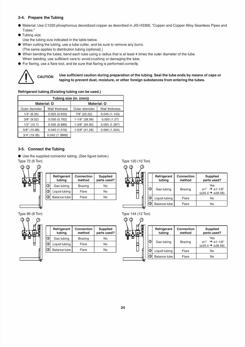
3-4. Prepare the Tubing
3-5. Connect the Tubing
4. ELECTRICAL WIRING . . . . . . . . . . . . . . . . . . 27
4-1. General Precautions on Wiring
4-2. Recommended Wire Length and Wire
Diameter for Power Supply System
4-3. Wiring System Diagram
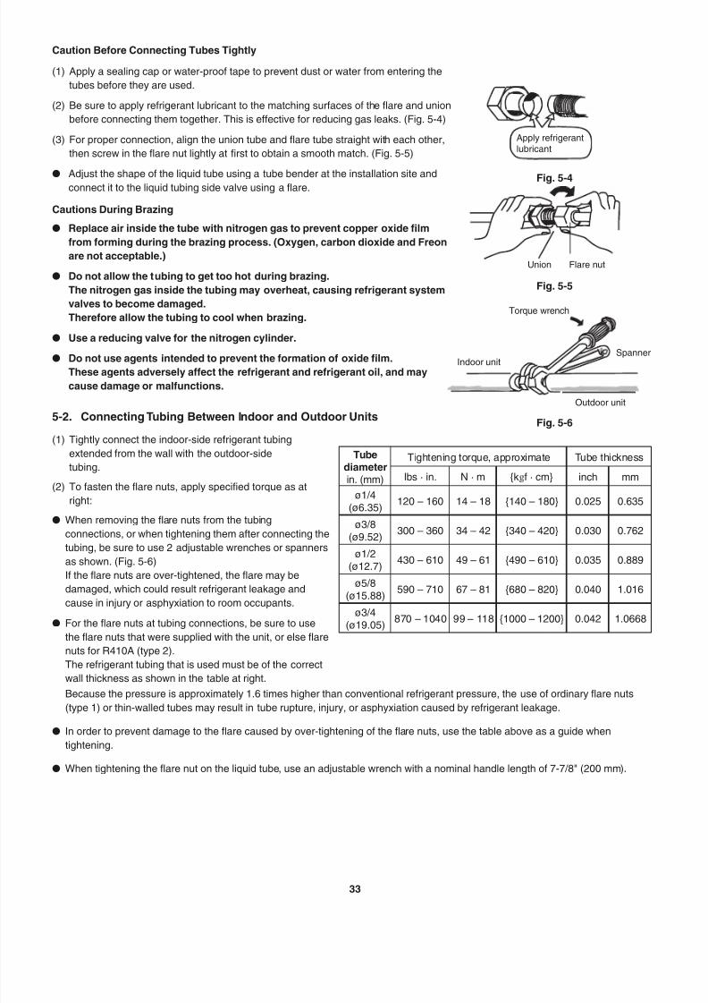
5. HOW TO PROCESS TUBING . . . . . . . . . . . . . 32
5-1. Connecting the Refrigerant Tubing
5-2. Connecting Tubing Between Indoor and
Outdoor Units
5-3. Insulating the Refrigerant Tubing
5-4. Taping the Tubes
5-5. Finishing the Installation
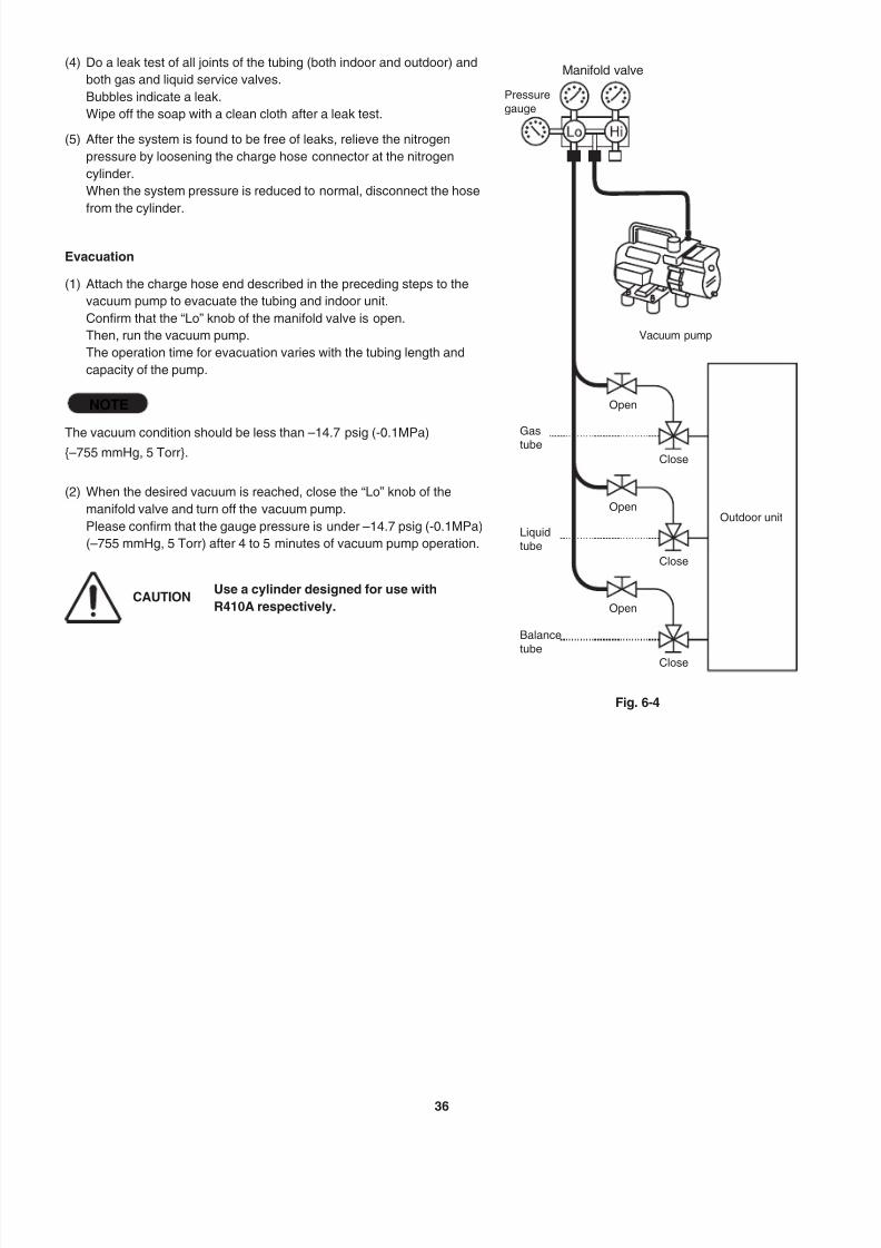
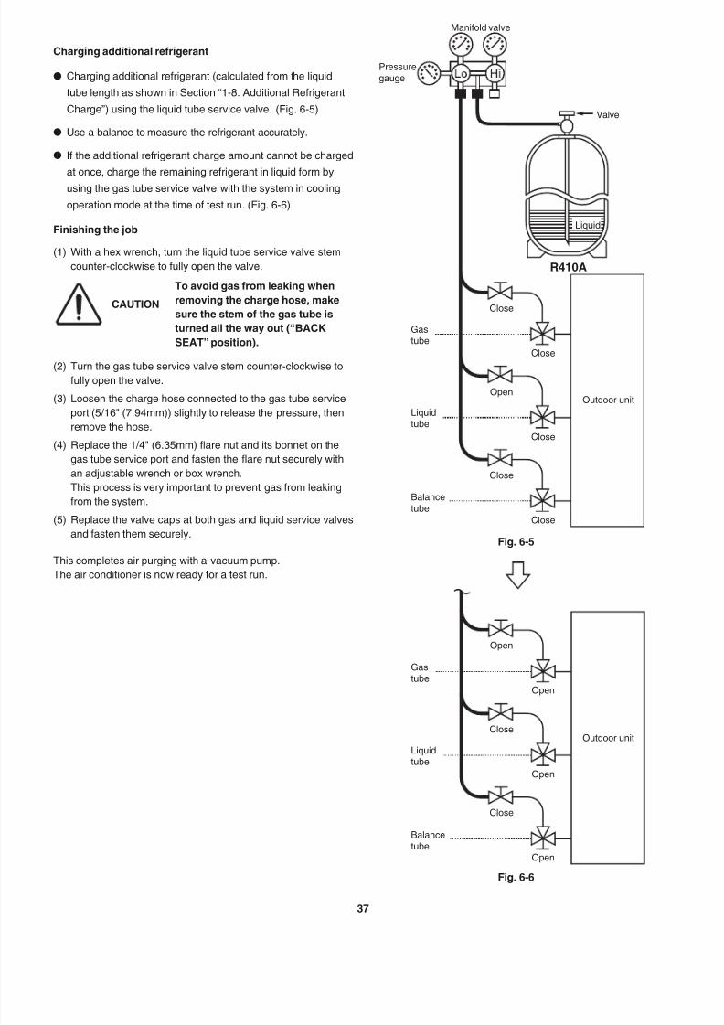
6. AIR PURGING . . . . . . . . . . . . . . . . . . . . . . . . . 35
n Air Purging with a Vacuum Pump (for Test Run)
Preparation
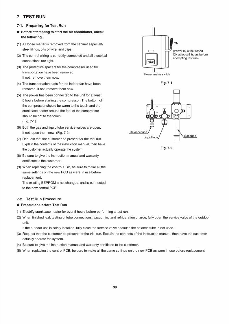
7. TEST RUN . . . . . . . . . . . . . . . . . . . . . . . . . . . . 38
7-1. Preparing for Test Run
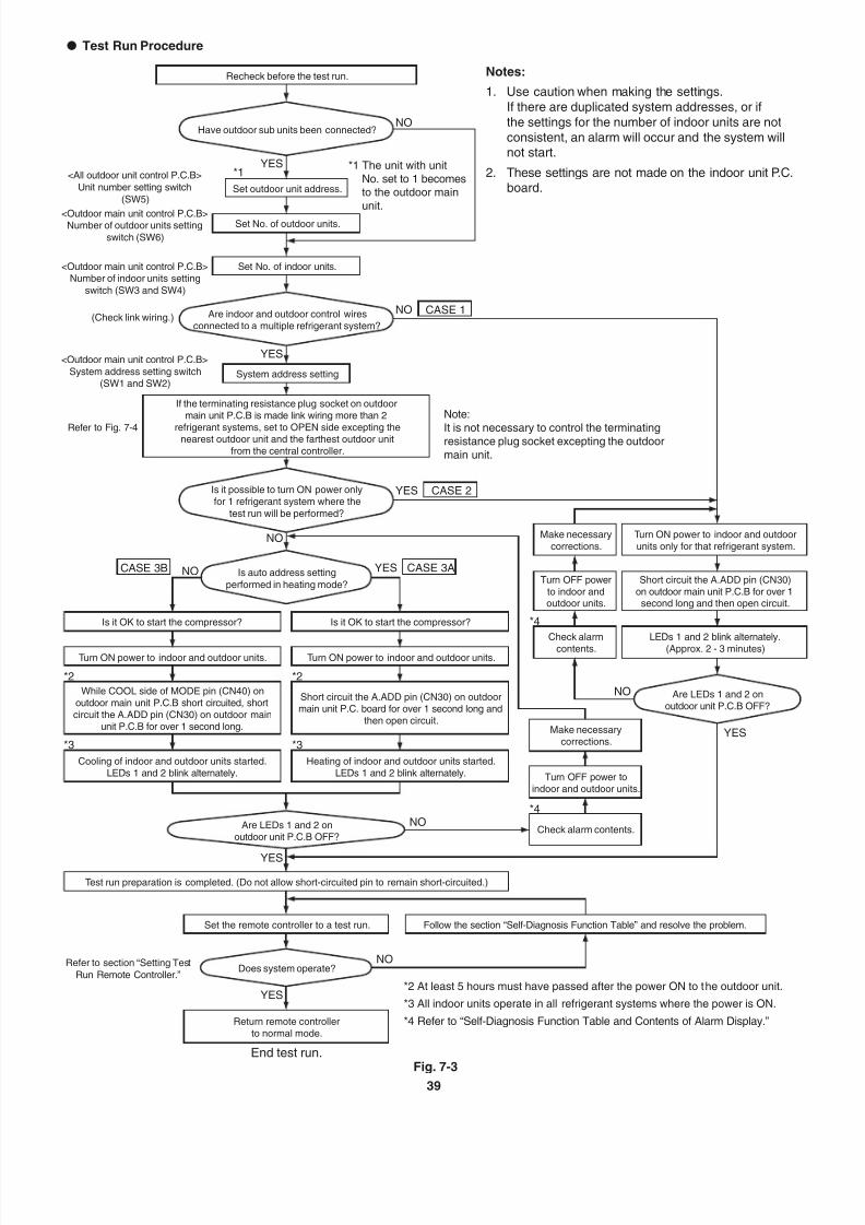
7-2. Test Run Procedure
7-3. Main Outdoor Unit PCB Setting
7-4. Function Switches on P.C. Board
7-5. Auto Address Setting
7-6. Setting Test Run Remote Controller
7-7. Caution for Pump Down
7-8. Self-Diagnosis Function Table and Contents of
Alarm Display
CONTENTS
Page Page
7/25/2019 Ex 2 Way Installation
http://slidepdf.com/reader/full/ex-2-way-installation 8/577
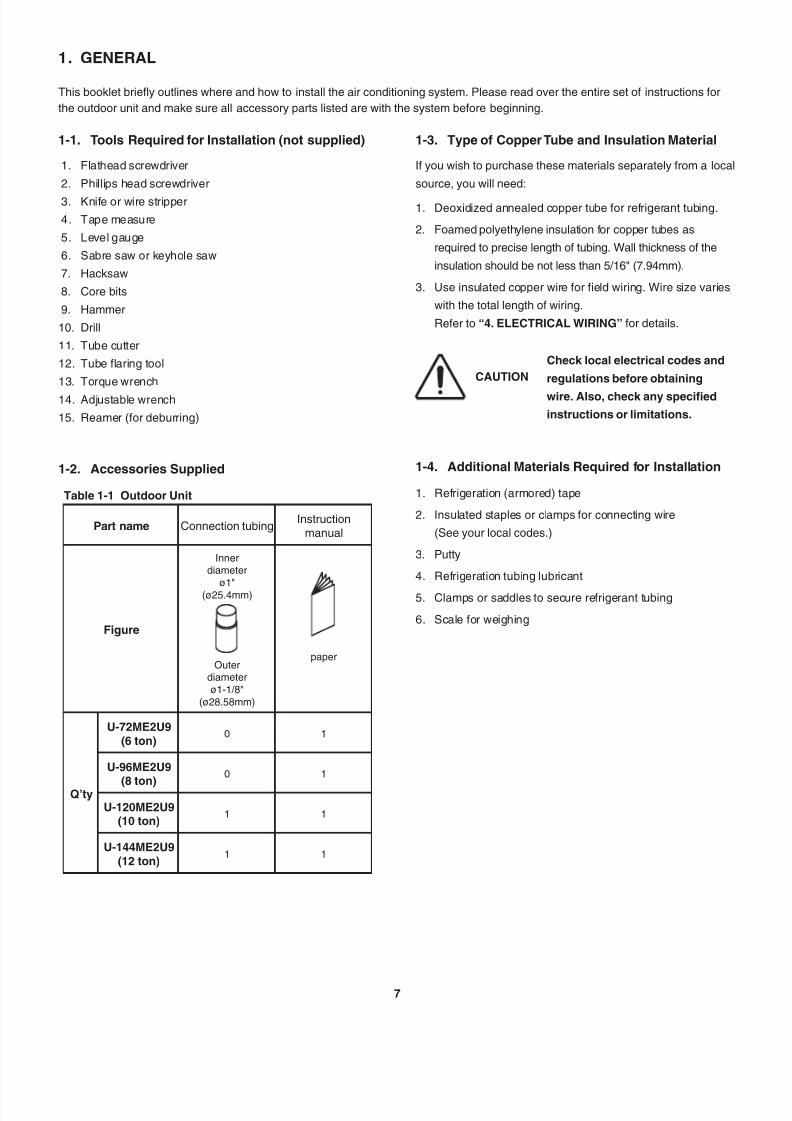
1. GENERAL
This booklet briefly outlines where and how to install the air conditioning system. Please read over the entire set of instructions for
the outdoor unit and make sure all accessory parts listed are with the system before beginning.
1-1. Tools Required for Installation (not supplied)
1. Flathead screwdriver
2. Phillips head screwdriver
3. Knife or wire stripper
4. Tape measure
5. Level gauge
6. Sabre saw or keyhole saw
7. Hacksaw
8. Core bits
9. Hammer
10. Drill
11. Tube cutter
12. Tube flaring tool
13. Torque wrench
14. Adjustable wrench
15. Reamer (for deburring)
1-2. Accessories Supplied
Table 1-1 Outdoor Unit
Part name Connection tubingInstruction
manual
Figure
Innerdiameter
ø1"(ø25.4mm)
Outerdiameterø1-1/8"
(ø28.58mm)
paper
Q’ty
U-72ME2U9
(6 ton)0 1
U-96ME2U9
(8 ton)
0 1
U-120ME2U9(10 ton)
1 1
U-144ME2U9
(12 ton)1 1
1-3. Type of Copper Tube and Insulation Material
If you wish to purchase these materials separately from a local
source, you will need:
1. Deoxidized annealed copper tube for refrigerant tubing.
2. Foamed polyethylene insulation for copper tubes as
required to precise length of tubing. Wall thickness of the
insulation should be not less than 5/16" (7.94mm).
3. Use insulated copper wire for field wiring. Wire size varies
with the total length of wiring.
Refer to “4. ELECTRICAL WIRING” for details.
CAUTION
Check local electrical codes and
regulations before obtaining
wire. Also, check any specified
instructions or limitations.
1-4. Additional Materials Required for Installation
1. Refrigeration (armored) tape
2. Insulated staples or clamps for connecting wire
(See your local codes.)
3. Putty
4. Refrigeration tubing lubricant
5. Clamps or saddles to secure refrigerant tubing
6. Scale for weighing
7/25/2019 Ex 2 Way Installation
http://slidepdf.com/reader/full/ex-2-way-installation 9/578
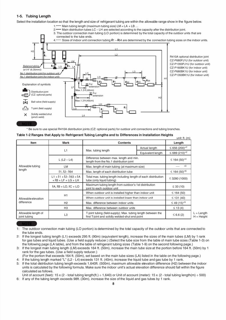
1-5. Tubing Length
Select the installation location so that the length and size of refrigerant tubing are within the allowable range show in the figure below.
NOTE
* Be sure to use special R410A distribution joints (CZ: optional parts) for outdoor unit connections and tubing branches.
Table 1-2 Ranges that Apply to Refrigerant Tubing Lengths and to Differences in Installation Heightsunit: ft. (m)
Item Mark Contents Length
Allowable tubinglength
L1 Max. tubing lengthActual length 656 (200)*2
Equivalent length 689 (210)*2
L (L2 – L4)Difference between max. length and min.length from the No.1 distribution joint
164 (50)*4
LM Max. length of main tubing (at maximum size) -
*
3
1, 2~ 64 Max. length of each distribution tube 164 (50)*6
L1 + 1 + 2~ 63 + A+ B + LF + LG + LH
Total max. tubing length including length of each distributiontube (only liquid tubing)
3280 (1000)
A, B + LO, C + LOMaximum tubing length from outdoor’s 1st distribution joint to each outdoor unit
33 (10)
Allowable elevationdifference
H1When outdoor unit is installed higher than indoor unit 164 (50)
When outdoor unit is installed lower than indoor unit 131 (40)
H2 Max. difference between indoor units 49 (15)*5
H3 Max. difference between outdoor units 13 (4)
Allowable length of joint tubing
L3T-joint tubing (field-supply); Max. tubing length between thefirst T-joint and solidly welded-shut end point
6.6 (2)L = LengthH = Height
NOTE1: The outdoor connection main tubing (LO portion) is determined by the total capacity of the outdoor units that are connected to
the tube ends.2: If the longest tubing length (L1) exceeds 295 ft. (90m) (equivalent length), increase the sizes of the main tubes (LM) by 1 rank
for gas tubes and liquid tubes. (Use a field supply reducer.) (Select the tube size from the table of main tube sizes (Table 1-3) onthe following page (LA table), and from the table of refrigerant tubing sizes (Table 1-9) on the second following page.)
3: If the longest main tubing length (LM) exceeds 164 ft. (50m), increase the main tube size at the portion before 164 ft. (50m) by 1rank for the gas tubes. (Use a field supply reducer.)(For the portion that exceeds 164 ft. (50m), set based on the main tube sizes (LA) listed in the table on the following page.)
4: If the tubing length marked "L" (L2 - L4) exceeds 131 ft. (40m), increase the liquid tube and gas tube by 1 rank.5: If the total distribution tubing length exceeds 1,640ft. (500m), maximum allowable elevation difference (H2) between the indoor
units is calculated by the following formula. Make sure the indoor unit’s actual elevation difference should fall within the figurecalculated as follows.Unit of account (feet): 15 x (2 - total tubing length(ft.) ÷ 1,640) or Unit of account (meter): 15 x (2 - total tubing length(m) ÷ 500)
6: If any of the tubing length exceeds 98ft. (30m), increase the size of the liquid and gas tubes by 1 rank.
R410A optional distribution jointCZ-P680PJ1U (for outdoor unit)
CZ-P1350PJ1U (for outdoor unit)
CZ-P160BK1U (for indoor unit)
CZ-P680BK1U (for indoor unit)
CZ-P1350BK1U (for indoor unit)
LO LA
LF
LM
LB
LC
L2
L4
LG
3L
LD
LH
H2
H3
H1
L1
23
1
54
AB
C
62 6364
Balance tubing
(ø1/4" (6.35mm))
Explanation of symbols
No.1 distribution joint for outdoor unit
No.1 distribution joint (for indoor unit)
Distribution joint
(CZ: optional parts)
Forextension
Forextension
Max.1.3 ft (40cm)
Max.1.3 ft (40cm)
Solidly welded shut(pinch weld)
Ball valve (field supply)
T-joint (field supply)
1. Main tubing length (maximum tubing size) LM = LA + LB …2. Main distribution tubes LC – LH are selected according to the capacity after the distribution joint.3. The outdoor connection main tubing (LO portion) is determined by the total capacity of the outdoor units that are
connected to the tube ends.4. Sizes of indoor unit connection tubing 1 – 64 are determined by the connection tubing sizes on the indoor units.

7/25/2019 Ex 2 Way Installation
http://slidepdf.com/reader/full/ex-2-way-installation 10/57
7/25/2019 Ex 2 Way Installation
http://slidepdf.com/reader/full/ex-2-way-installation 11/5710
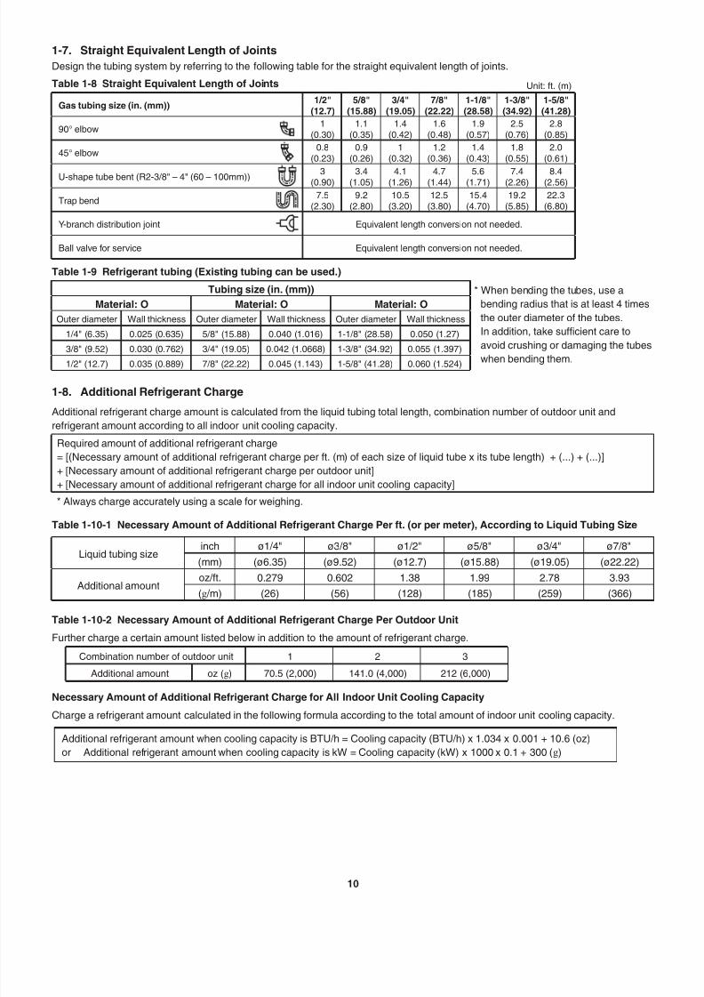
1-7. Straight Equivalent Length of Joints
Design the tubing system by referring to the following table for the straight equivalent length of joints.
Table 1-8 Straight Equivalent Length of Joints Unit: ft. (m)
Gas tubing size (in. (mm))1/2"
(12.7)5/8"
(15.88)3/4"
(19.05)7/8"
(22.22)1-1/8"(28.58)
1-3/8"(34.92)
1-5/8"(41.28)
90° elbow1
(0.30)1.1
(0.35)1.4
(0.42)1.6
(0.48)1.9
(0.57)2.5
(0.76)2.8
(0.85)
45° elbow0.8
(0.23)0.9
(0.26)1
(0.32)1.2
(0.36)1.4
(0.43)1.8
(0.55)2.0
(0.61)
U-shape tube bent (R2-3/8" – 4" (60 – 100mm)) 3(0.90) 3.4(1.05) 4.1(1.26) 4.7(1.44) 5.6(1.71) 7.4(2.26) 8.4(2.56)
Trap bend7.5
(2.30)9.2
(2.80)10.5
(3.20)12.5
(3.80)15.4
(4.70)19.2
(5.85)22.3
(6.80)
Y-branch distribution joint Equivalent length conversion not needed.
Ball valve for service Equivalent length conversion not needed.
Table 1-9 Refrigerant tubing (Existing tubing can be used.)
Tubing size (in. (mm)) * When bending the tubes, use a
bending radius that is at least 4 times
the outer diameter of the tubes.
In addition, take sufficient care to
avoid crushing or damaging the tubeswhen bending them.
Material: O Material: O Material: O
Outer diameter Wall thickness Outer diameter Wall thickness Outer diameter Wall thickness
1/4" (6.35) 0.025 (0.635) 5/8" (15.88) 0.040 (1.016) 1-1/8" (28.58) 0.050 (1.27)
3/8" (9.52) 0.030 (0.762) 3/4" (19.05) 0.042 (1.0668) 1-3/8" (34.92) 0.055 (1.397)1/2" (12.7) 0.035 (0.889) 7/8" (22.22) 0.045 (1.143) 1-5/8" (41.28) 0.060 (1.524)
1-8. Additional Refrigerant Charge
Additional refrigerant charge amount is calculated from the liquid tubing total length, combination number of outdoor unit and
refrigerant amount according to all indoor unit cooling capacity.
Required amount of additional refrigerant charge
= [(Necessary amount of additional refrigerant charge per ft. (m) of each size of liquid tube x its tube length) + (...) + (...)]
+ [Necessary amount of additional refrigerant charge per outdoor unit]
+ [Necessary amount of additional refrigerant charge for all indoor unit cooling capacity]
* Always charge accurately using a scale for weighing.
Table 1-10-1 Necessary Amount of Additional Refrigerant Charge Per ft. (or per meter), According to Liquid Tubing Size
Liquid tubing sizeinch ø1/4" ø3/8" ø1/2" ø5/8" ø3/4" ø7/8"
(mm) (ø6.35) (ø9.52) (ø12.7) (ø15.88) (ø19.05) (ø22.22)
Additional amountoz/ft. 0.279 0.602 1.38 1.99 2.78 3.93
(g /m) (26) (56) (128) (185) (259) (366)
Table 1-10-2 Necessary Amount of Additional Refrigerant Charge Per Outdoor Unit
Further charge a certain amount listed below in addition to the amount of refrigerant charge.
Combination number of outdoor unit 1 2 3
Additional amount oz (g) 70.5 (2,000) 141.0 (4,000) 212 (6,000)
Necessary Amount of Additional Refrigerant Charge for All Indoor Unit Cooling CapacityCharge a refrigerant amount calculated in the following formula according to the total amount of indoor unit cooling capacity.
Additional refrigerant amount when cooling capacity is BTU/h = Cooling capacity (BTU/h) x 1.034 x 0.001 + 10.6 (oz)
or Additional refrigerant amount when cooling capacity is kW = Cooling capacity (kW) x 1000 x 0.1 + 300 (g)
7/25/2019 Ex 2 Way Installation
http://slidepdf.com/reader/full/ex-2-way-installation 12/57
7/25/2019 Ex 2 Way Installation
http://slidepdf.com/reader/full/ex-2-way-installation 13/57

7/25/2019 Ex 2 Way Installation
http://slidepdf.com/reader/full/ex-2-way-installation 14/5713
3. CZ-P160BK1U
Use: For indoor unit (Capacity after distribution joint is 76,400 BTU/h (22.4 kW) or less.)
4-21/64
(110)
4-21/64
(110)
(97)3-13/16 3-13/16
(97)2 - 5 3 / 6 4
( 7 2 )
2 - 5 3 / 6 4
( 7 2 )
B A D
B
BC
C
C D E
A
CDE
C
Example: Gas tubing Liquid tubing
DistributionJoint
DistributionJointInsulation Insulation
Unit: in. (mm)
Table 1-15 Size of connection point on each part (Shown are inside diameters of tubing)
Size Part A Part B Part C Part D Part E
in. (mm)ø3/4"
(ø19.05)ø5/8"
(ø15.88)ø1/2"
(ø12.7)ø3/8"
(ø9.52)ø1/4"
(ø6.35)
4. CZ-P680BK1U
Use: For indoor unit (Capacity after distribution joint is greater than 76,400 BTU/h (22.4 kW) and no more than 232,000 BTU/h (68.0 kW).)
6-57/64
(175)5-5/16
(135)
4-21/64
(110)
(97)
3-13/16
E
E
FG
FGH
B
CD
EF
EB C D F GHD C BE F
4 - 3 1 / 6 4
( 1 1 4 )
2 - 5 3 / 6 4
( 7 2 )
A
A
A
Example: Gas tubing Liquid tubing
DistributionJoint
DistributionJoint
Insulation
Insulation
ReducingJoints
ReducingJoints
Unit: in. (mm)
Table 1-16 Size of connection point on each part (Shown are inside diameters of tubing)
Size Part A Part B Part C Part D Part E Part F Part G Part H
in. (mm)ø1-1/8"(ø28.58)
ø1"(ø25.4)
ø7/8"(ø22.22)
ø3/4"(ø19.05)
ø5/8"(ø15.88)
ø1/2"(ø12.7)
ø3/8"(ø9.52)
ø1/4"(ø6.35)
5. CZ-P1350BK1U
Use: For indoor unit (Capacity after distribution joint is greater than 232,000 BTU/h (68.0 kW) and no more than 460,700 BTU/h (135.0 kW).)
(175)
(135)
4-21/64
(110)
(97)
3-13/16
4 - 3 1 / 6 4
( 1 1 4 )
2 - 5 3 / 6 4
( 7 2 )
6-57/64
5-5/16
HIJ
C
D
EF
GH
G
F F
H
G
GBCD
B
B
A
C D
A
A
Unit: in. (mm)
Gas tubing Liquid tubingExample:
Distribution
Joint
Distribution
Joint
Insulation
Insulation
ReducingJointsReducing
Joints: Outside dimension
Table 1-17 Size of connection point on each part (Shown are inside diameters of tubing)
Size Part A Part B Part C Part D Part E Part F Part G Part H Part I Part J
in. (mm)ø1-3/8"(ø34.92)
ø1-1/4"(ø31.75)
ø1-1/8"(ø28.58)
ø1"(ø25.4)
ø7/8"(ø22.22)
ø3/4"(ø19.05)
ø5/8"(ø15.88)
ø1/2"(ø12.7)
ø3/8"(ø9.52)
ø1/4"(ø6.35)

7/25/2019 Ex 2 Way Installation
http://slidepdf.com/reader/full/ex-2-way-installation 15/57
7/25/2019 Ex 2 Way Installation
http://slidepdf.com/reader/full/ex-2-way-installation 16/5715
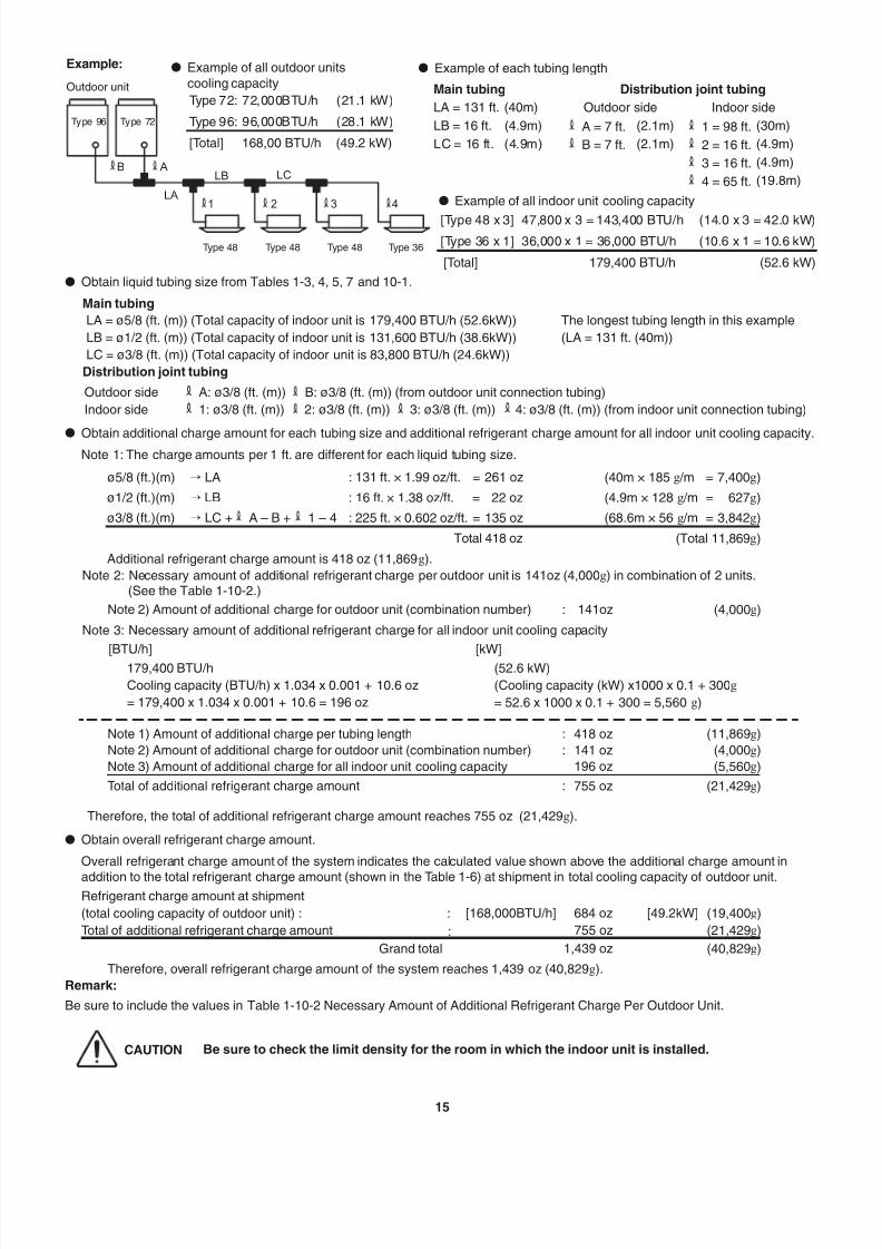
l Obtain liquid tubing size from Tables 1-3, 4, 5, 7 and 10-1.
Main tubing
LA = ø5/8 (ft. (m)) (Total capacity of indoor unit is 179,400 BTU/h (52.6kW))
LB = ø1/2 (ft. (m)) (Total capacity of indoor unit is 131,600 BTU/h (38.6kW))
LC = ø3/8 (ft. (m)) (Total capacity of indoor unit is 83,800 BTU/h (24.6kW))
The longest tubing length in this example
(LA = 131 ft. (40m))
Distribution joint tubing
Outdoor side A: ø3/8 (ft. (m)) B: ø3/8 (ft. (m)) (from outdoor unit connection tubing)
Indoor side 1: ø3/8 (ft. (m)) 2: ø3/8 (ft. (m)) 3: ø3/8 (ft. (m)) 4: ø3/8 (ft. (m)) (from indoor unit connection tubing)
lObtain additional charge amount for each tubing size and additional refrigerant charge amount for all indoor unit cooling capacity.
Note 1: The charge amounts per 1 ft. are different for each liquid tubing size.
ø5/8 (ft.)(m) í LA : 131 ft. × 1.99 oz/ft. = 261 oz (40m × 185 g /m = 7,400g)
ø1/2 (ft.)(m) í LB : 16 ft. × 1.38 oz/ft. = 22 oz (4.9m × 128 g /m = 627g)
ø3/8 (ft.)(m) í LC + A – B + 1 – 4 : 225 ft. × 0.602 oz/ft. = 135 oz (68.6m × 56 g /m = 3,842g)
Total 418 oz (Total 11,869g)
Additional refrigerant charge amount is 418 oz (11,869g).
Note 2: Necessary amount of additional refrigerant charge per outdoor unit is 141oz (4,000g) in combination of 2 units.(See the Table 1-10-2.)
Note 2) Amount of additional charge for outdoor unit (combination number) : 141oz (4,000g)
Note 3: Necessary amount of additional refrigerant charge for all indoor unit cooling capacity
[BTU/h] [kW]
179,400 BTU/h
Cooling capacity (BTU/h) x 1.034 x 0.001 + 10.6 oz
= 179,400 x 1.034 x 0.001 + 10.6 = 196 oz
(52.6 kW)
(Cooling capacity (kW) x1000 x 0.1 + 300g
= 52.6 x 1000 x 0.1 + 300 = 5,560 g)
Note 1) Amount of additional charge per tubing length : 418 oz (11,869g)
Note 2) Amount of additional charge for outdoor unit (combination number) : 141 oz (4,000g)
Note 3) Amount of additional charge for all indoor unit cooling capacity 196 oz (5,560g)
Total of additional refrigerant charge amount : 755 oz (21,429g)
Therefore, the total of additional refrigerant charge amount reaches 755 oz (21,429g).
l Obtain overall refrigerant charge amount.
Overall refrigerant charge amount of the system indicates the calculated value shown above the additional charge amount in
addition to the total refrigerant charge amount (shown in the Table 1-6) at shipment in total cooling capacity of outdoor unit.Refrigerant charge amount at shipment
(total cooling capacity of outdoor unit) : : [168,000BTU/h] 684 oz [49.2kW] (19,400g)
Total of additional refrigerant charge amount : 755 oz (21,429g)
Grand total 1,439 oz (40,829g)
Therefore, overall refrigerant charge amount of the system reaches 1,439 oz (40,829g).
Remark:
Be sure to include the values in Table 1-10-2 Necessary Amount of Additional Refrigerant Charge Per Outdoor Unit.
CAUTION Be sure to check the limit density for the room in which the indoor unit is installed.
1 2 3 4LA
LB LC AB
Example:
Outdoor unit
Type 96 Type 72
Type 48 Type 48 Type 48 Type 36
l Example of each tubing length
Main tubing Distribution joint tubing
LA = 131 ft. (40m) Outdoor side Indoor side
LB = 16 ft. (4.9m) A = 7 ft. (2.1m) 1 = 98 ft. (30m)
LC = 16 ft. (4.9m) B = 7 ft. (2.1m) 2 = 16 ft. (4.9m)
3 = 16 ft. (4.9m)
4 = 65 ft. (19.8m)
l Example of all indoor unit cooling capacity
[Type 48 x 3] 47,800 x 3 = 143,400 BTU/h (14.0 x 3 = 42.0 kW)
[Type 36 x 1] 36,000 x 1 = 36,000 BTU/h (10.6 x 1 = 10.6 kW)
[Total] 179,400 BTU/h (52.6 kW)
l Example of all outdoor unitscooling capacity
Type 72: 72,000BTU/h (21.1 kW)
Type 96: 96,000BTU/h (28.1 kW)
[Total] 168,00 BTU/h (49.2 kW)
7/25/2019 Ex 2 Way Installation
http://slidepdf.com/reader/full/ex-2-way-installation 17/5716
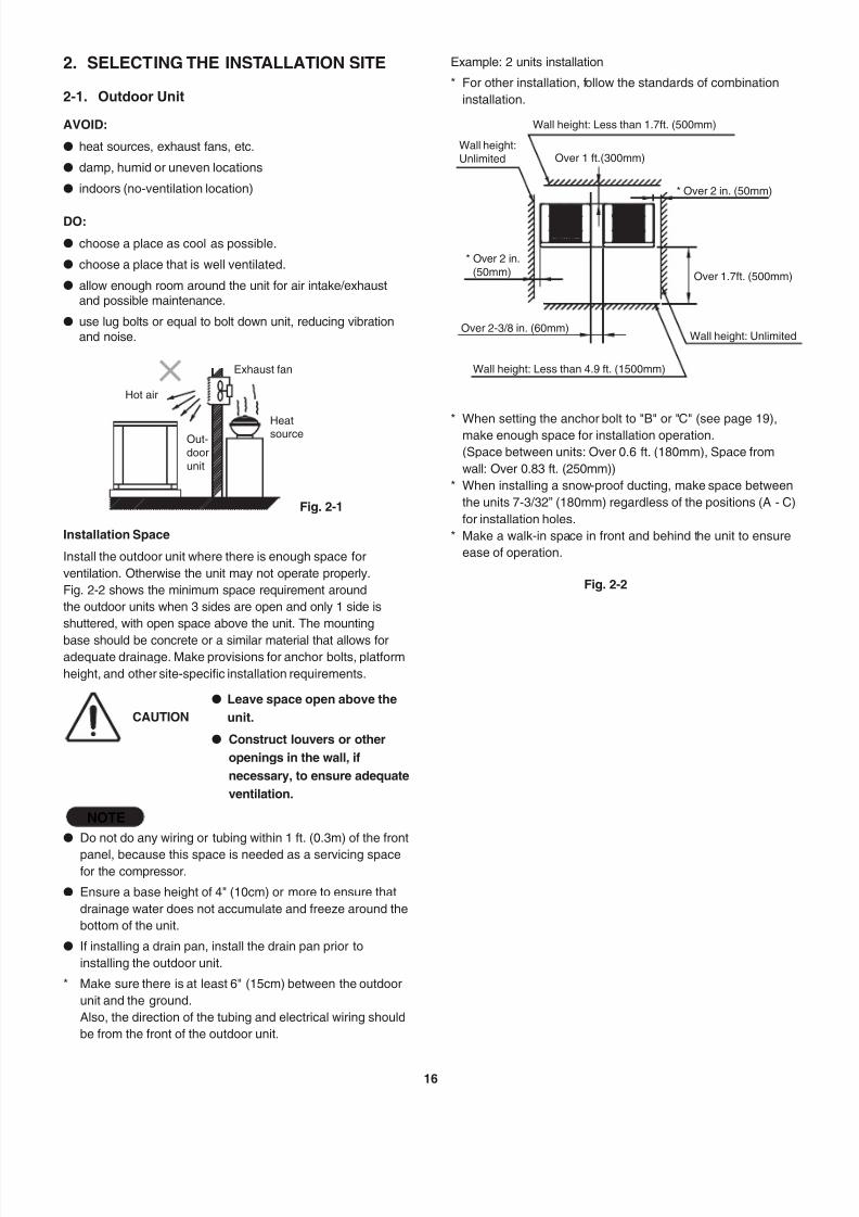
2. SELECTING THE INSTALLATION SITE
2-1. Outdoor Unit
AVOID:
l heat sources, exhaust fans, etc.
l damp, humid or uneven locations
l indoors (no-ventilation location)
DO:
l choose a place as cool as possible.
l choose a place that is well ventilated.
l allow enough room around the unit for air intake/exhaustand possible maintenance.
l use lug bolts or equal to bolt down unit, reducing vibration
and noise.
Exhaust fan
Fig. 2-1
Hot air
HeatsourceOut-doorunit
Installation Space
Install the outdoor unit where there is enough space for
ventilation. Otherwise the unit may not operate properly.
Fig. 2-2 shows the minimum space requirement around
the outdoor units when 3 sides are open and only 1 side is
shuttered, with open space above the unit. The mounting
base should be concrete or a similar material that allows foradequate drainage. Make provisions for anchor bolts, platform
height, and other site-specific installation requirements.
CAUTION
l Leave space open above the
unit.
l Construct louvers or other
openings in the wall, if
necessary, to ensure adequate
ventilation.
NOTE
l Do not do any wiring or tubing within 1 ft. (0.3m) of the front
panel, because this space is needed as a servicing spacefor the compressor.
l Ensure a base height of 4" (10cm) or more to ensure that
drainage water does not accumulate and freeze around the
bottom of the unit.
l If installing a drain pan, install the drain pan prior to
installing the outdoor unit.
* Make sure there is at least 6" (15cm) between the outdoor
unit and the ground.
Also, the direction of the tubing and electrical wiring should
be from the front of the outdoor unit.
Wall height: Less than 1.7ft. (500mm)
Over 1 ft.(300mm)
* Over 2 in. (50mm)
* Over 2 in.(50mm) Over 1.7ft. (500mm)
Wall height: Unlimited
Wall height: Less than 4.9 ft. (1500mm)
Over 2-3/8 in. (60mm)
Wall height:Unlimited
Example: 2 units installation
* For other installation, follow the standards of combination
installation.
* When setting the anchor bolt to "B" or "C" (see page 19),
make enough space for installation operation.
(Space between units: Over 0.6 ft. (180mm), Space from
wall: Over 0.83 ft. (250mm))
* When installing a snow-proof ducting, make space between
the units 7-3/32” (180mm) regardless of the positions (A - C)
for installation holes.
* Make a walk-in space in front and behind the unit to ensure
ease of operation.
Fig. 2-2
7/25/2019 Ex 2 Way Installation
http://slidepdf.com/reader/full/ex-2-way-installation 18/5717
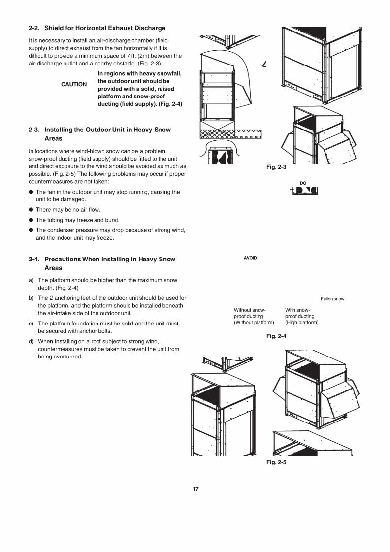
2-2. Shield for Horizontal Exhaust Discharge
It is necessary to install an air-discharge chamber (field
supply) to direct exhaust from the fan horizontally if it is
difficult to provide a minimum space of 7 ft. (2m) between the
air-discharge outlet and a nearby obstacle. (Fig. 2-3)
CAUTION
In regions with heavy snowfall,
the outdoor unit should be
provided with a solid, raised
platform and snow-proofducting (field supply). (Fig. 2-4)
2-3. Installing the Outdoor Unit in Heavy Snow
Areas
In locations where wind-blown snow can be a problem,
snow-proof ducting (field supply) should be fitted to the unit
and direct exposure to the wind should be avoided as much as
possible. (Fig. 2-5) The following problems may occur if proper
countermeasures are not taken:
l The fan in the outdoor unit may stop running, causing theunit to be damaged.
l There may be no air flow.
l The tubing may freeze and burst.
l The condenser pressure may drop because of strong wind,
and the indoor unit may freeze.
2-4. Precautions When Installing in Heavy Snow
Areas
a) The platform should be higher than the maximum snow
depth. (Fig. 2-4)b) The 2 anchoring feet of the outdoor unit should be used for
the platform, and the platform should be installed beneath
the air-intake side of the outdoor unit.
c) The platform foundation must be solid and the unit must
be secured with anchor bolts.
d) When installing on a roof subject to strong wind,
countermeasures must be taken to prevent the unit from
being overturned.
Fig. 2-3
Fig. 2-4
Fallen snow
DO
AVOID
Without snow-proof ducting(Without platform)
With snow-proof ducting(High platform)
Fig. 2-5

7/25/2019 Ex 2 Way Installation
http://slidepdf.com/reader/full/ex-2-way-installation 19/57

7/25/2019 Ex 2 Way Installation
http://slidepdf.com/reader/full/ex-2-way-installation 20/5719
Reference diagram for air-discharge chamber (field supply) (continued)
Combination of units
For various types of combination, refer to Technical Data.
unit: in. (mm)
J
K
E
G
E
J
K
GJ
K
F
H
ML
D
LM
D
LM
FI I
1 0 1 - 3 / 1 6
( 2 5 7 0 )
2 8 - 5 5 / 6 4
( 7 3 3 )
39-31/64(1003)3/64 (1) 5/64 (2)
Top view(Before installing air-discharge chamber)
Top view
C
: 2 8 - 4
7 / 6 4 ( 7 3 0 ) I n s
t a l l a t i o n
h o
l e p
i t c h
B :
2 8 - 4
7 / 6 4 ( 7 3 0 ) I n s
t a l l a t i o n
h o
l e p
i t c h d o w n w a r d
t u b i n g
d i r e c
t i o n
A :
3 7 - 6
1 / 6 4 ( 9 6 4 ) I n s
t a l l a t i o n
h o
l e p
i t c h f o r w a r d
t u b i n g
d i r e c
t i o n
Front view Right side view
According to the installation site, you may choose the setting position in the depth direction of the anchor bolt from “A”, “B” or “C”.
Sample of small size models (3 units):
D E F G H I J K L M
A :
Installation hole pitch
2-23/64
(60)
2-1/8
(54)
95-29/32
(2,436)
3-35/64
(90)
94-31/64
(2,400)
3-15/64
(82)
29-9/64
(740)
30-35/64
(776)
29-29/64
(748)
27-43/64
(703)B :
Installation hole pitch7-3/32(180)
6-27/32(174)
105-23/64(2,676)
8-17/64(210)
103-15/16(2,640)
7-61/64(202)
29-9/64(740)
30-35/64(776)
29-29/64(748)
27-43/64(703)
C :Installation hole pitch
7-3/32(180)
6-27/32(174)
105-23/64(2,676)
8-17/64(210)
103-15/16(2,640)
7-61/64(202)
29-9/64(740)
30-35/64(776)
29-29/64(748)
27-43/64(703)
Sample of middle size models (3 units):
D E F G H I J K L M
A :Installation hole pitch
2-23/64(60)
2-1/8(54)
144-21/64(3,666)
3-35/64(90)
142-29/32(3,630)
3-15/64(82)
45-9/32(1,150)
46-11/16(1,186)
45-19/32(1,158)
43-13/16(1,113)
B :Installation hole pitch
7-3/32(180)
6-27/32(174)
153-25/32(3,906)
8-17/64(210)
152-23/64(3,870)
7-61/64(202)
45-9/32(1,150)
46-11/16(1,186)
45-19/32(1,158)
43-13/16(1,113)
C :Installation hole pitch
7-3/32(180)
6-27/32(174)
153-25/32(3,906)
8-17/64(210)
152-23/64(3,870)
7-61/64(202)
45-9/32(1,150)
46-11/16(1,186)
45-19/32(1,158)
43-13/16(1,113)
7/25/2019 Ex 2 Way Installation
http://slidepdf.com/reader/full/ex-2-way-installation 21/5720
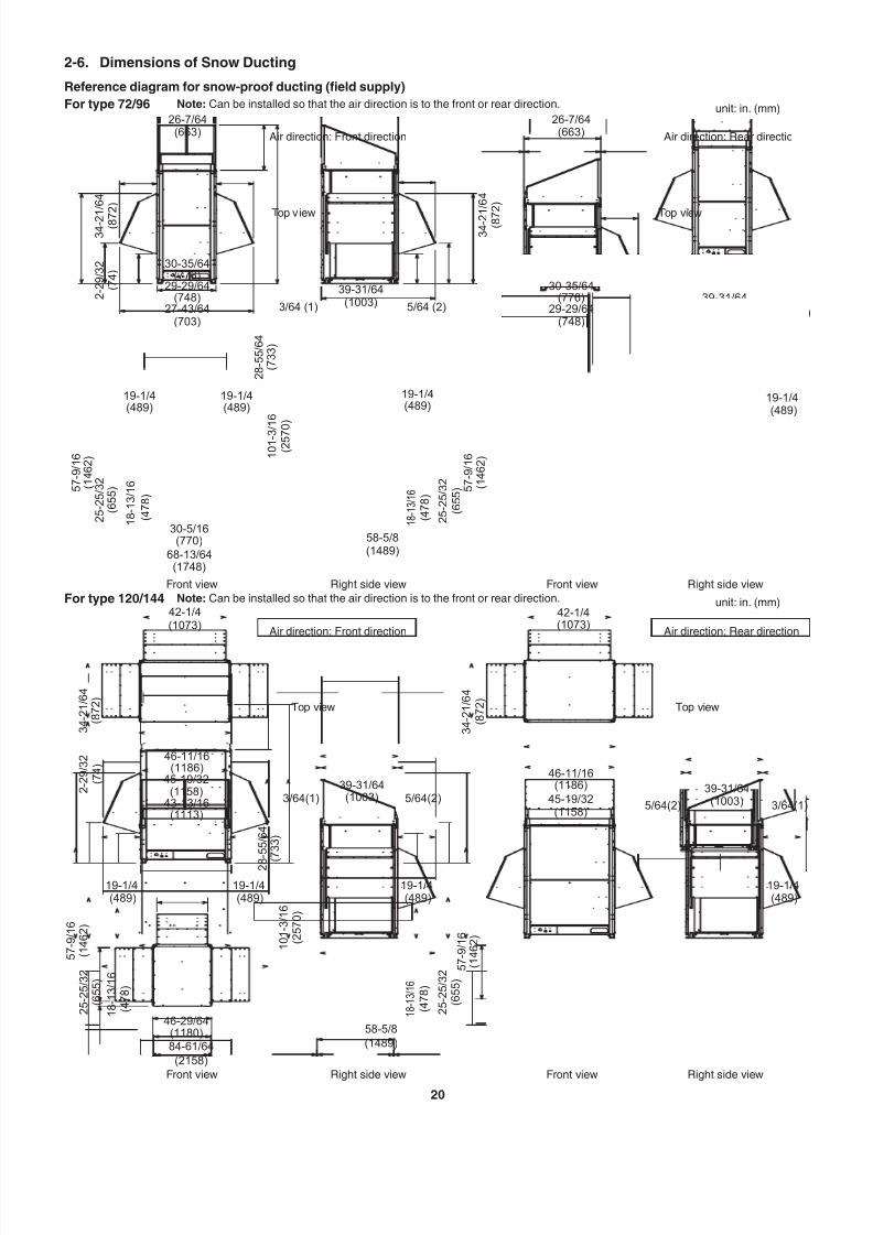
2-6. Dimensions of Snow Ducting
Reference diagram for snow-proof ducting (field supply)
For type 72/96 Note: Can be installed so that the air direction is to the front or rear direction.
For type 120/144 Note: Can be installed so that the air direction is to the front or rear direction.
3 4 - 2 1 / 6 4
2 - 2 9 / 3 2
( 8 7
2 )
3 4 - 2
1 / 6 4
( 8 7
2 )
( 7 4 )
26-7/64(663)
26-7/64(663)
39-31/64(1003) 39-31/64
(1003)
58-5/8(1489)
1 8 -
1 3 / 1 6
( 4 7 8 )
2 5 - 2 5 / 3 2
( 6 5 5 ) 5
7 - 9 / 1 6
( 1 4 6 2 )
2 8 - 5 5 / 6 4
( 7 3 3 )
1 0 1 - 3
/ 1 6
( 2 5 7
0 )
29-29/64(748)
27-43/64(703)
30-35/64(776)
29-29/64(748)
30-35/64(776)
19-1/4(489)
19-1/4(489)
19-1/4(489)
19-1/4(489)
3/64 (1) 5/64 (2)5/64 (2) 3/64 (1)
68-13/64(1748)
30-5/16(770)
( 4 7 8 )
1 8 - 1 3 / 1 6
2 5 - 2 5 / 3 2
( 6 5 5 ) 5
7 - 9 / 1 6
( 1 4 6 2 )
unit: in. (mm)
Top viewTop view
Air direction: Rear directionAir direction: Front direction
Front view Right side view Front view Right side view
1 8 -
1 3 / 1 6
( 4 7 8 )
19-1/4(489)
19-1/4(489)
19-1/4(489)
42-1/4(1073)
3 4 - 2 1 / 6 4
( 8 7 2 )
3 4 - 2 1 / 6 4
( 8 7 2 )
2 - 2 9 / 3 2
( 7 4 )
(1073)42-1/4
39-31/64(1003) 3/64(1)5/64(2)
45-19/32(1158)
46-11/16(1186)39-31/64
(1003) 5/64(2)3/64(1)
58-5/8
(1489)
2 5 - 2 5 / 3 2
( 6 5 5 )
5 7 - 9 / 1 6
( 1 4 6 2 )
2 8 - 5 5 / 6 4
( 7 3 3 )
1 0 1 - 3 / 1 6
( 2 5 7 0 )
45-19/32(1158)
43-13/16(1113)
46-11/16(1186)
84-61/64
(2158)
46-29/64(1180)
1 8 - 1 3 / 1 6
( 4 7 8 )
2 5 - 2 5 / 3 2
( 6 5 5 )
5 7 - 9 / 1 6
( 1 4 6 2 )
19-1/4(489)
unit: in. (mm)
Top viewTop view
Air direction: Rear directionAir direction: Front direction
Front view Right side view Front view Right side view

7/25/2019 Ex 2 Way Installation
http://slidepdf.com/reader/full/ex-2-way-installation 22/5721
Reference diagram for snow-proof ducting (field supply) (continued)
Combination of units
For various types of combination, refer to Technical Data.unit: in. (mm)
D
E
8-17/64 (210) 8-17/64 (210)
7-3/32 (180) 7-3/32 (180)
E
DD
E
3 9 - 3 / 8
( 1 0 0 0 )
G
2 - 2 9 / 3 2
( 7 4 )
3 4 - 2 1 / 6 4
( 8 7 2 )
2 - 2 9 / 3 2
( 7 4 )
3 4 - 2 1 / 6 4
( 8 7 2 )
H
7-61/64 (202)
2 0 - 9 / 3 2
( 5 1 5 )
2 0 - 9 / 3 2
( 5 1 5 )
1 8 -
1 3 / 1 6
( 4 7 8 )
1 8 - 1 3 / 1 6
( 4 7 8 )
1 8 -
1 3 / 1 6
( 4 7 8 )
19-1/4
(489)
19-1/4
(489)
19-19/
(490
7-61/64 (202)
5 7 - 2 3 / 3 2
( 1 4 6 6 )
5 7 - 2 3 / 3 2
( 1 4 6 6 )
2 5 - 2 5 / 3 2
( 6 5 5 )
5
7 - 9 / 1 6
( 1 4 6 2 )
35/64
(14)
35/64 (14)
F
I
5 7 -
9 / 1 6
( 1 4
6 2 )
2 5 - 2 5 / 3 2
( 6 5 5 )
2 8 - 5 5 / 6 4
( 7 3 3 )
1 0 1 - 3 / 1 6
( 2 5 7 0 )
2 5 - 5 3 / 6 4
( 6 5 6 ) 5
7 - 9
/ 1 6
39-31/64(1003)
3/64 (1) 5/64 (2)
Top view(Before installing snow-proof ducting)
Top view
C
: 2 8 - 4
7 / 6 4 ( 7 3 0 ) I n s
t a l l a t i o n
h o
l e p
i t c h
B :
2 8 - 4
7 / 6 4 ( 7 3 0 ) I n s
t a l l a t i o n
h o
l e p
i t c h
d o w n w a r d
t u b i n g
d i r e c
t i o n
A :
3 7 - 6
1 / 6 4 ( 9 6 4 ) I n s
t a l l a t i o n
h o
l e p i
t c h f o r w a r d
t u b i n g
d i r e c
t i o n
Front view Right side view
According to the installation site, you may choose the setting position in the depth direction of the anchor bolt from “A”, “B” or “C”.
Sample of small size models (3 units):
D E F G H I
A : Installation hole pitch
29-9/64(740)
30-5/16(770)
105-23/64(2,676)
105-1/8(2,670)
100-29/32(2,563)
143-5/8(3,648)
B : Installation hole pitch
C : Installation hole pitch
Sample of middle size models (3 units):
D E F G H I
A : Installation hole pitch
45-9/32(1,150)
46-29/64(1,180)
153-25/32(3,906)
153-35/64(3,900)
149-21/64(3,793)
192-3/64(4,878)
B : Installation hole pitch
C : Installation hole pitch

7/25/2019 Ex 2 Way Installation
http://slidepdf.com/reader/full/ex-2-way-installation 23/57

7/25/2019 Ex 2 Way Installation
http://slidepdf.com/reader/full/ex-2-way-installation 24/5723
3-3. Routing the Tubing
l The tubing can be routed out either from the front or from the bottom. (Fig. 3-5)
l The connecting valve is contained inside the unit. Therefore, remove the front panel. (Fig. 3-5)
(1) If the tubing is routed out from the front, use cutting pliers or a similar tool to cut out the tubing outlet slit (part indicated by )
from the tubing cover. (Figs. 3-5 and 3-6)
3 9 - 3 / 8 ( 1 0 0 0 )
3 9 - 3 / 8 ( 1 0 0 0 )
A A
4 5 / 6 4 ( 1 8 )
4 5 / 6 4 ( 1 8 )
B B
C C
29-9/64 (740) 45-9/32 (1150)
30-5/16 (770) 46-29/64 (1180)
19/32 (15) 19/32 (15)
Type 72/96 Type 120/144Unit: in. (mm)
Air intake Air intake
(Installation hole pitch) (Installation hole pitch)
A i r i n t a k e
A i r i n t a k e
A i r i n t a k e
A i r i n t a k e
A : 37-61/64 (964) [Installation hole pitch] * The tubing is routed out from the front.
B : 28-47/64 (730) [Installation hole pitch] * The tubing is routed out from the bottom.
C : 28-47/64 (730) [Installation hole pitch] Fig. 3-4
For type 72/96
FrontFront
Tubing cover
Tubing cover
Tubing cover
Slit part
Slit hole
Remove 2 screws
Indentation (5 locations)
Use cutting pliers or similar toolto cut cover out
Remove 10 panel screwsfrom front panel
Remove 8 panel screwsfrom front panel
Bottom Bottom
For type 120/144 ex.) type 72/96
Fig. 3-5
Fig. 3-6
(2) If the tubing is routed out from the bottom, remove the slit part ( ).
l Use a drill bit approximately 13/64" (5.2 mm) dia. to create holes at the
5 slit hole indentations (openings).
l Punch out the slit part ( ).
l Be careful not to damage the base plate.
7/25/2019 Ex 2 Way Installation
http://slidepdf.com/reader/full/ex-2-way-installation 25/57

7/25/2019 Ex 2 Way Installation
http://slidepdf.com/reader/full/ex-2-way-installation 26/5725
Refrigerant tube port
l Use caulking, putty, or a similar material to fill any gaps at the
refrigerant tube port ( ) in order to prevent rainwater, dust or
foreign substances from entering the unit.
* Perform this work even if the tubing is routed out in a downward
direction.
l Tighten each cap as specified below.
Tightening torque for each capCap tightening torque
Width unit: lbs · inch unit: N · m {unit: kgf · cm}
Service port cap 43/64" (17mm) 90 - 100 10 - 12 {100 - 120}
Valve cap
35/64" (14mm),43/64" (17 mm)
170 - 220 20 - 25 {200 - 250}
3/4" (19 mm) 120 - 170 14 - 20 {140 - 200}
17/16" (27mm) 190 - 240 22 - 28 {220 - 280}
Tubing cover
Tubing routed out
through the front side
Bottom plate
Tubing routed out
through the bottom
For type 72
Service port capwidth 43/64 (17)
Valve capwidth 3/4 (19)
Valve capwidth 35/64 (14)
Valve capwidth 35/64 (14)
Service port capwidth 43/64 (17)
Service port capwidth 43/64 (17)
Flare nutø1/4 (6.35)
Flare nutø3/8 (9.52)
For type 120/144
Service port capwidth 43/64 (17)
Valve capwidth 17/16 (27)
Valve capwidth 35/64 (14)
Valve capwidth 43/64 (17)
Service port capwidth 43/64 (17)
Service port cap
width 43/64 (17)
Flare nutø1/4 (6.35)
Flare nut
ø1/2 (12.7)
For type 96Unit: in. (mm)
Service port capwidth 43/64 (17)
Valve capwidth 3/4 (19)
Valve capwidth 35/64 (14)
Valve capwidth 43/64 (17)
Service port capwidth 43/64 (17)
Service port capwidth 43/64 (17)
Flare nutø1/4 (6.35)
Flare nutø3/8 (9.52)
Do not apply an adjustable wrench
to the hexagonal part.
Use two adjustable wrenches, as shown in the figure,
when removing the liquid tube valve flare nut.
Do not use two adjustable wrenches when removing or
installing the balance tube flare nut. In particular, do not
apply an adjustable wrench to the hexagonal part at the top
of the valve. (If force is applied to this part, gas leakage will
occur.)
1. Do not apply a wrench to the valve cap when
removing or installing the flare nuts.
Doing so may damage the valve.
2. If the valve cap is left off for a long period of time,
refrigerant leakage will occur.
Therefore, do not leave the valve cap off.
3. Applying refrigerant oil to the flare surface can be
effective in preventing gas leakage, however be
sure to use a refrigerant oil which is suitable for
the refrigerant that is used in the system. (This unit
utilizes R410A refrigerant, and the refrigerant oil is
ether oil (synthetic oil).
However, hub oil (synthetic oil) can also be used.)

7/25/2019 Ex 2 Way Installation
http://slidepdf.com/reader/full/ex-2-way-installation 27/5726
l Precautions for brazing
Be sure to replace the air inside the tube with nitrogen to prevent
oxide film from forming during the brazing process. Be sure to use
a damp cloth or other means to cool the valve unit during brazing.
CAUTION
1. Be sure to use nitrogen. (Oxygen, CO2, and CFC must not be used.)
2. Use a pressure-reducing valve on the nitrogen tank.
3. Do not use agents intended to prevent the formation of oxide film.
They will adversely affect the refrigeration oil, and may cause equipment failure.
4. The balance tube is not used if only 1 outdoor unit is installed.
Use the unit in the same conditions as when it was shipped from the factory.
Work methodPressure-reducingvalve (regulator)
Field-supply tube
Brazing locations Taping
Ni t r o g en
Remote valve

7/25/2019 Ex 2 Way Installation
http://slidepdf.com/reader/full/ex-2-way-installation 28/57
7/25/2019 Ex 2 Way Installation
http://slidepdf.com/reader/full/ex-2-way-installation 29/5728
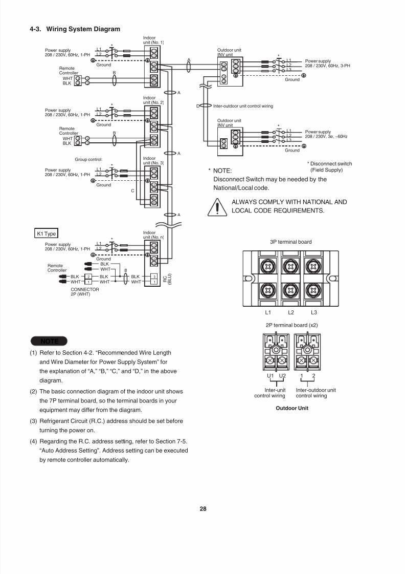
NOTE
(1) Refer to Section 4-2. “Recommended Wire Length
and Wire Diameter for Power Supply System” for
the explanation of “A,” “B,” “C,” and “D,” in the above
diagram.
(2) The basic connection diagram of the indoor unit shows
the 7P terminal board, so the terminal boards in yourequipment may differ from the diagram.
(3) Refrigerant Circuit (R.C.) address should be set before
turning the power on.
(4) Regarding the R.C. address setting, refer to Section 7-5.
“Auto Address Setting”. Address setting can be executed
by remote controller automatically.
4-3. Wiring System Diagram
2
1
B
1
3
*
*
*
*
*
*
U2
U1
L2
L1
R2
R1
2
U2
1
U1
2
1
2
1
2
1
B
C
A
L1
L2
L3
L1
L2
L1
L2
L1
L2
L1
L2
2
1
2
1
L1
L2
L3
D
B
A
U2
U1
L2
L1
R2
R1
U2
U1
L2
L1
R2
R1
U2
U1
L2
L1
A
A
L2
L1
L3
L2
L1
L3
Power supply208 / 230V, 60Hz, 1-PH
Power supply208 / 230V, 60Hz, 1-PH
Power supply208 / 230V, 60Hz, 1-PH
Power supply208 / 230V, 60Hz, 1-PH
RemoteController
CONNECTOR2P (WHT)
R C
( B L U )
Power supply208 / 230V, 60Hz, 3-PH
Power supply208 / 230V, 3ø, ~60Hz
* Disconnect switch(Field Supply)* NOTE:
Disconnect Switch may be needed by the
National/Local code.
ALWAYS COMPLY WITH NATIONAL ANDLOCAL CODE REQUIREMENTS.
RemoteController
RemoteController
Indoorunit (No. 1)
Indoorunit (No. 2)
Indoorunit (No. 3)
Indoorunit (No. n)
Outdoor unitINV unit
Outdoor unitINV unit
WHTBLK
WHTBLK
BLK
WHTBLK
WHTBLK
WHT
BLK
WHT
Ground
Ground
Ground
Ground
K1 Type
Group control:
Ground
Ground
Inter-outdoor unit control wiring
L2 L3L1
3P terminal board
U1 1U2 2
2P terminal board (x2)
Outdoor Unit
Inter-unitcontrol wiring
Inter-outdoor unitcontrol wiring

7/25/2019 Ex 2 Way Installation
http://slidepdf.com/reader/full/ex-2-way-installation 30/5729
CAUTION
(1) When linking outdoor units in a network, disconnect the terminal extended from the short plug (CN67, 2P Black,
location: left bottom on the outdoor main control PCB) from all outdoor units except any one of the outdoor units.
(When shipping: In shorted condition.)
For a system without link (no connection wiring between outdoor units), do not remove the short plug.
(2) Do not install the inter-unit control wiring in a way that forms a loop. (Fig. 4-1)
Fig. 4-1
Outdoor unit
Indoor unit Indoor unit Indoor unit Indoor unit Indoor unit
Outdoor unit Outdoor unit
Prohibited
Prohibited
(3) Do not install inter-unit control wiring such as star branch
wiring. Star branch wiring causes mis-address setting.
Outdoor unit Indoor unit Indoor unit
Indoor unit Indoor unitNOBranch point
Fig. 4-2
(4) If branching the inter-unit control wiring, the number of branch points should be 16 or fewer.
Outdoor unit
Outdoor unit
Outdoor unit
Indoor unit
Central Controller
Indoor unit
Indoor unit
Indoor unit
Indoor unit
Indoor unit
Indoor unit
Indoor unit
Indoor unit
M o r e
t h a n
7 f t . ( 2 m
) r e q u
i r e d
: Branch point
Fig. 4-3
7/25/2019 Ex 2 Way Installation
http://slidepdf.com/reader/full/ex-2-way-installation 31/57
7/25/2019 Ex 2 Way Installation
http://slidepdf.com/reader/full/ex-2-way-installation 32/5731
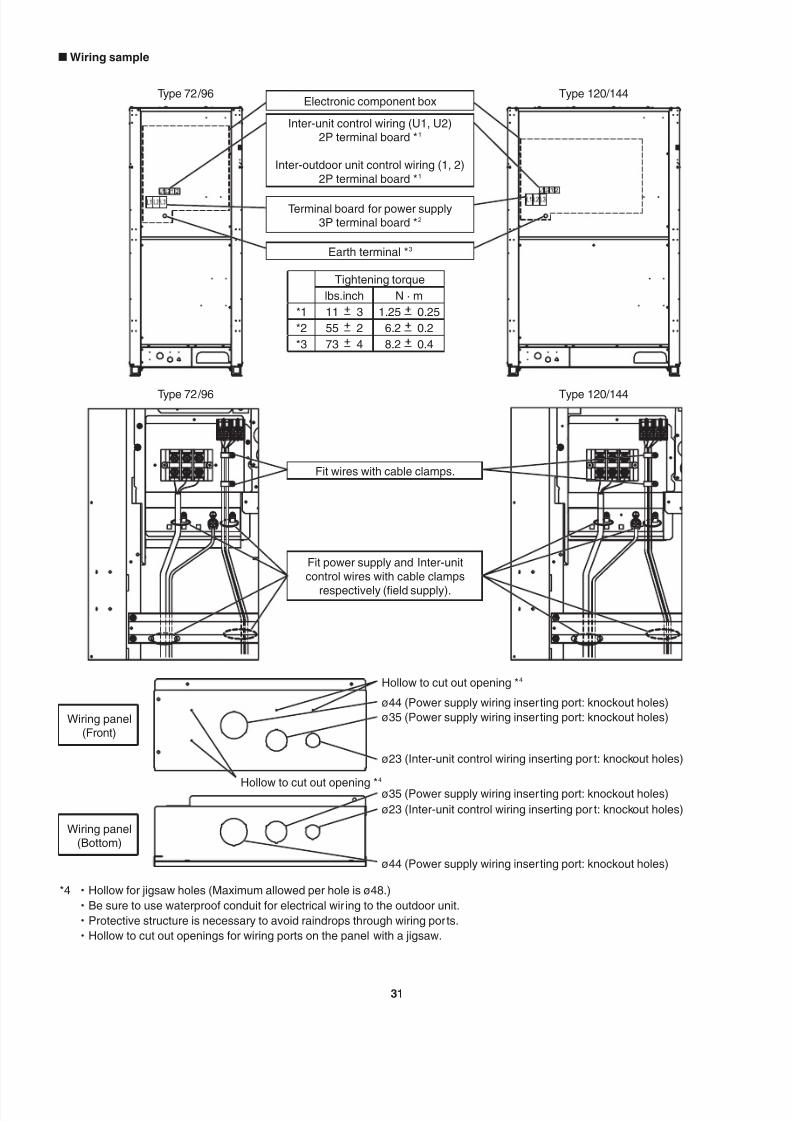
n Wiring sample
Type 72/96
Type 72/96
Electronic component box
Earth terminal *3
Fit wires with cable clamps.
Fit power supply and Inter-unit
control wires with cable clamps
respectively (field supply).
Wiring panel(Front)
Wiring panel(Bottom)
Terminal board for power supply3P terminal board *2
Inter-unit control wiring (U1, U2)2P terminal board *1
Inter-outdoor unit control wiring (1, 2)
2P terminal board *1
Type 120/144
Type 120/144
Tightening torque
lbs.inch N · m
*1 11 3 1.25 0.25
*2 55 2 6.2 0.2
*3 73 4 8.2 0.4
Hollow to cut out opening *4
Hollow to cut out opening *4
ø44 (Power supply wiring inserting port: knockout holes)
ø35 (Power supply wiring inserting port: knockout holes)
ø23 (Inter-unit control wiring inserting por t: knockout holes)
ø35 (Power supply wiring inserting port: knockout holes)
ø23 (Inter-unit control wiring inserting por t: knockout holes)
ø44 (Power supply wiring inserting port: knockout holes)
*4 ・Hollow for jigsaw holes (Maximum allowed per hole is ø48.)
・Be sure to use waterproof conduit for electrical wir ing to the outdoor unit.
・Protective structure is necessary to avoid raindrops through wiring ports.
・Hollow to cut out openings for wiring ports on the panel with a jigsaw.
7/25/2019 Ex 2 Way Installation
http://slidepdf.com/reader/full/ex-2-way-installation 33/5732
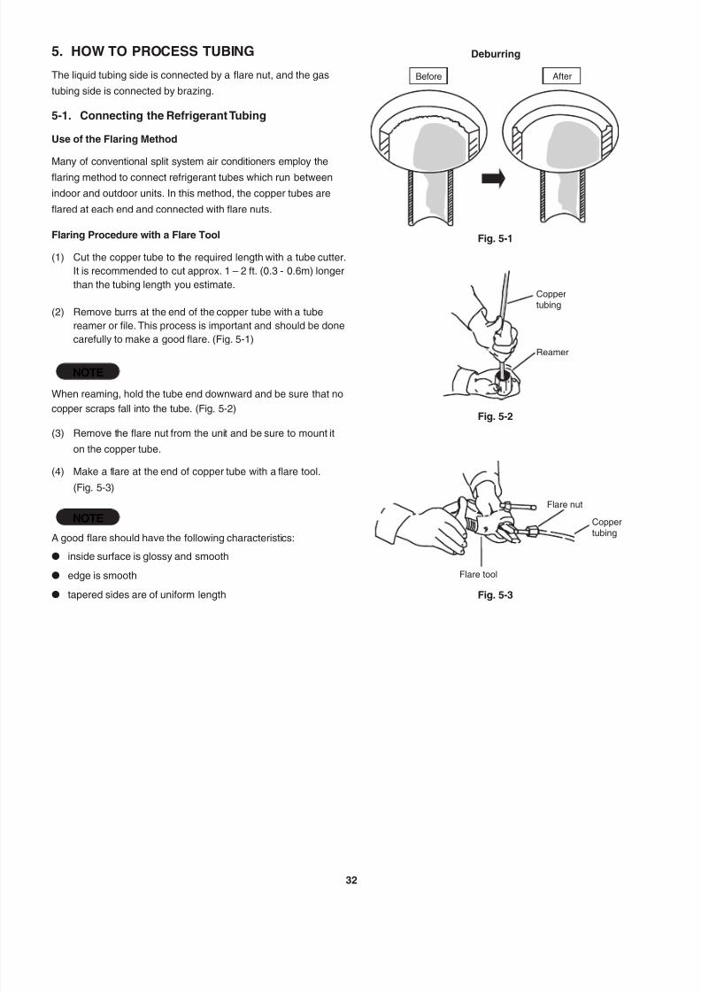
5. HOW TO PROCESS TUBING
The liquid tubing side is connected by a flare nut, and the gas
tubing side is connected by brazing.
5-1. Connecting the Refrigerant Tubing
Use of the Flaring Method
Many of conventional split system air conditioners employ the
flaring method to connect refrigerant tubes which run between
indoor and outdoor units. In this method, the copper tubes are
flared at each end and connected with flare nuts.
Flaring Procedure with a Flare Tool
(1) Cut the copper tube to the required length with a tube cutter.
It is recommended to cut approx. 1 – 2 ft. (0.3 - 0.6m) longer
than the tubing length you estimate.
(2) Remove burrs at the end of the copper tube with a tube
reamer or file. This process is important and should be done
carefully to make a good flare. (Fig. 5-1)
NOTE
When reaming, hold the tube end downward and be sure that no
copper scraps fall into the tube. (Fig. 5-2)
(3) Remove the flare nut from the unit and be sure to mount it
on the copper tube.
(4) Make a flare at the end of copper tube with a flare tool.
(Fig. 5-3)
NOTEA good flare should have the following characteristics:
l inside surface is glossy and smooth
l edge is smooth
l tapered sides are of uniform length
Deburring
Fig. 5-1
Before After
Fig. 5-2
Coppertubing
Reamer
Fig. 5-3
Flare nut
Flare tool
Coppertubing
7/25/2019 Ex 2 Way Installation
http://slidepdf.com/reader/full/ex-2-way-installation 34/57

7/25/2019 Ex 2 Way Installation
http://slidepdf.com/reader/full/ex-2-way-installation 35/57

7/25/2019 Ex 2 Way Installation
http://slidepdf.com/reader/full/ex-2-way-installation 36/57
7/25/2019 Ex 2 Way Installation
http://slidepdf.com/reader/full/ex-2-way-installation 37/57
7/25/2019 Ex 2 Way Installation
http://slidepdf.com/reader/full/ex-2-way-installation 38/57
7/25/2019 Ex 2 Way Installation
http://slidepdf.com/reader/full/ex-2-way-installation 39/57
7/25/2019 Ex 2 Way Installation
http://slidepdf.com/reader/full/ex-2-way-installation 40/57

7/25/2019 Ex 2 Way Installation
http://slidepdf.com/reader/full/ex-2-way-installation 41/57
7/25/2019 Ex 2 Way Installation
http://slidepdf.com/reader/full/ex-2-way-installation 42/5741
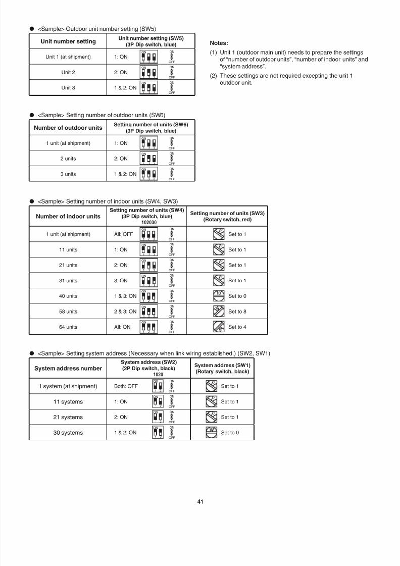
l <Sample> Outdoor unit number setting (SW5)
Unit number settingUnit number setting (SW5)
(3P Dip switch, blue)
Unit 1 (at shipment) 1: ON21 3
ON ON
OFF
Unit 2 2: ON1 2 3
ON ON
OFF
Unit 3 1 & 2: ON321
ON ON
OFF
l <Sample> Setting number of outdoor units (SW6)
Number of outdoor unitsSetting number of units (SW6)
(3P Dip switch, blue)
1 unit (at shipment) 1: ON21 3
ON ON
OFF
2 units 2: ON1 2 3
ON ON
OFF
3 units 1 & 2: ON321
ON ON
OFF
l <Sample> Setting number of indoor units (SW4, SW3)
Number of indoor unitsSetting number of units (SW4)
(3P Dip switch, blue)Setting number of units (SW3)
(Rotary switch, red)
1 unit (at shipment) All: OFF1 2 3
ON ON
OFF
1
Set to 1
11 units 1: ON21 3
ON ON
OFF
1
Set to 1
21 units 2: ON1 2 3
ON ON
OFF
1
Set to 1
31 units 3: ON321
ON ON
OFF
1
Set to 1
40 units 1 & 3: ON 1 2 3
ON ON
OFF
0
Set to 0
58 units 2 & 3: ON1 2 3
ON ON
OFF
8Set to 8
64 units All: ON1 2 3
ON ON
OFF
4 Set to 4
l <Sample> Setting system address (Necessary when link wiring established.) (SW2, SW1)
System address numberSystem address (SW2)(2P Dip switch, black)
System address (SW1)(Rotary switch, black)
1 system (at shipment) Both: OFF21
ON ON
OFF
1
Set to 1
11 systems 1: ON21
ON ON
OFF
1
Set to 1
21 systems 2: ON21
ON ON
OFF
1
Set to 1
30 systems 1 & 2: ON1 2
ON ON
OFF
0Set to 0
102030
1020
Notes:
(1) Unit 1 (outdoor main unit) needs to prepare the settingsof “number of outdoor units”, “number of indoor units” and
“system address”.
(2) These settings are not required excepting the unit 1
outdoor unit.

7/25/2019 Ex 2 Way Installation
http://slidepdf.com/reader/full/ex-2-way-installation 43/5742
7-4. Function Switches on P.C. Board
Function Switch Remarks
MODE pin (3P, BLK)
(CN40)
Changes to cooling/heating mode. (outdoor main unit is only usable.)
When in normal operation: When short circuited the COOL side, indoor unit operation in the same
refrigerant system changes to all cooling mode.
When short circuited the HEAT side, indoor unit operation in the same
refrigerant system changes to all heating mode.
When in auto address setting: Changes to heating mode with open-circuit.
A.ADD pin (2P, WHT)
(CN30)
Short circuited for over 1 second long Auto address setting starts with open-circuit.
If short circuit lasts for over 1 second long during auto address setting, the setting is interrupted.
CHK pin (2P, WHT)(CN23)
When short circuited, test run begins.(If the remote controller is connected in test run mode, it is automatically cancelled after 1 hour.)
Also, if short-circuit is cancelled, test run mode is cancelled.
RC plug (3P, BLU)
(CN73)Connects to outdoor unit maintenance remote controller and content of alarm message will be
checked.
RUN pin (2P, WHT)(CN27)
When short circuited and pulse signal is given, all indoor units operate in the same refrigerant system.
STOP pin (2P, WHT)(CN28) When short circuited and pulse signal is given, all indoor units stop in the same refrigerant system.(When short circuited, operation cannot be performed by the indoor unit's remote controller.)
AP pin (2P, WHT)(CN24)
Can be used when vacuuming the outdoor unit.
SNOW plug (3P, RD)(CN34)
Can be used when installing a snowfall sensor device.
SILENT plug (2P, WHT)
(CN33)Can be used when setting the outdoor unit fan in sound absorbing mode.
For details, refer to Test Run Service Manual.
7/25/2019 Ex 2 Way Installation
http://slidepdf.com/reader/full/ex-2-way-installation 44/5743
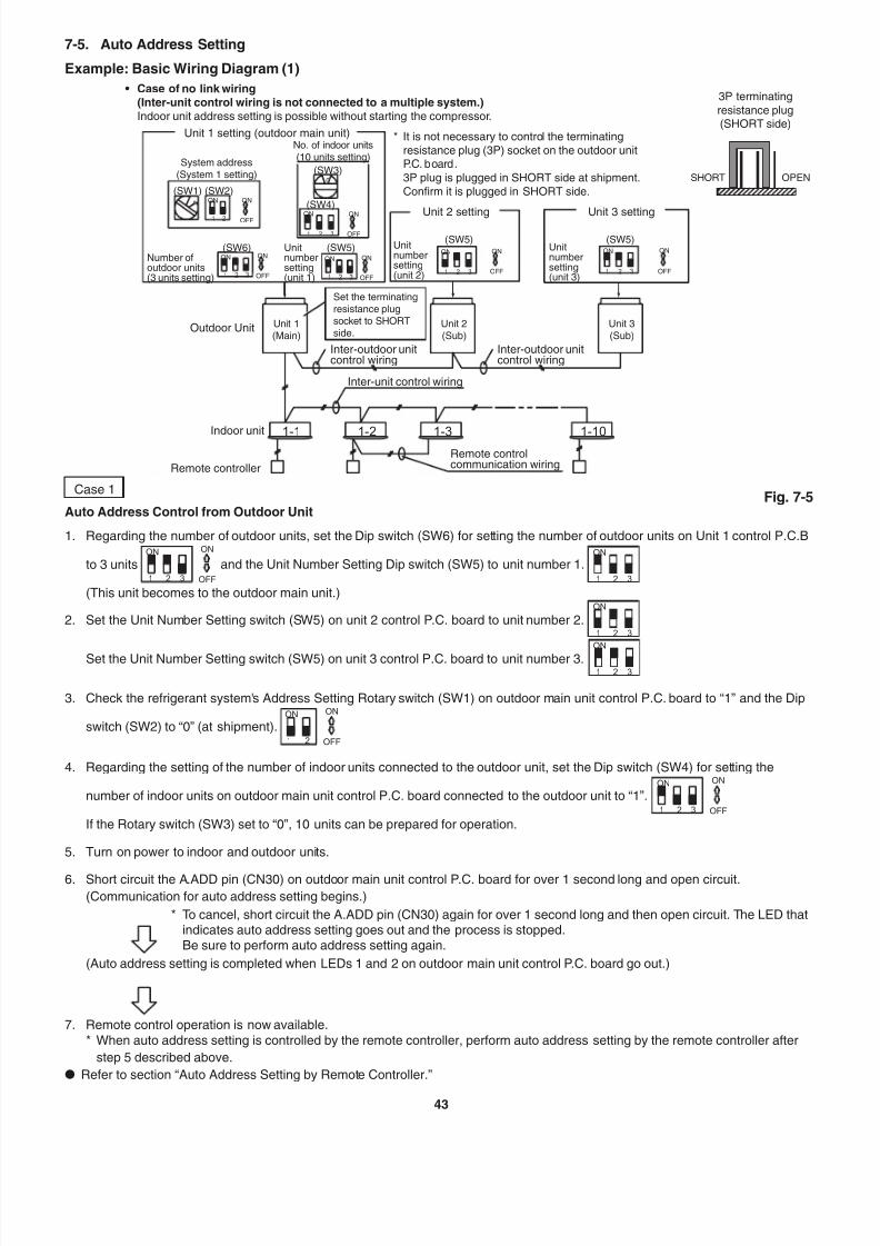
Case 1
Auto Address Control from Outdoor Unit
1. Regarding the number of outdoor units, set the Dip switch (SW6) for setting the number of outdoor units on Unit 1 control P.C.B
to 3 units1 2 3
ON ON
OFF
and the Unit Number Setting Dip switch (SW5) to unit number 1.2 31
ON
(This unit becomes to the outdoor main unit.)
2. Set the Unit Number Setting switch (SW5) on unit 2 control P.C. board to unit number 2.321
ON
Set the Unit Number Setting switch (SW5) on unit 3 control P.C. board to unit number 3.321
ON
3. Check the refrigerant system's Address Setting Rotary switch (SW1) on outdoor main unit control P.C. board to “1”
and the Dip
switch (SW2) to “0” (at shipment).1 2
ON ON
OFF
4. Regarding the setting of the number of indoor units connected to the outdoor unit, set the Dip switch (SW4) for setting the
number of indoor units on outdoor main unit control P.C. board connected to the outdoor unit to “1”.2 31
ON ON
OFF
If the Rotary switch (SW3) set to “0”, 10 units can be prepared for operation.
5. Turn on power to indoor and outdoor units.
6. Short circuit the A.ADD pin (CN30) on outdoor main unit control P.C. board for over 1 second long and open circuit.
(Communication for auto address setting begins.)
* To cancel, short circuit the A.ADD pin (CN30) again for over 1 second long and then open circuit. The LED thatindicates auto address setting goes out and the process is stopped.Be sure to perform auto address setting again.
(Auto address setting is completed when LEDs 1 and 2 on outdoor main unit control P.C. board go out.)
7. Remote control operation is now available.
* When auto address setting is controlled by the remote controller, perform auto address setting by the remote controller after
step 5 described above.
l Refer to section “Auto Address Setting by Remote Controller.”
7-5. Auto Address Setting
Example: Basic Wiring Diagram (1)
• Case of no link wiring (Inter-unit control wiring is not connected to a multiple system.)Indoor unit address setting is possible without starting the compressor.
1 2 3 321
1 32
1 2
21 3321
0
1
1-1 1-2 1-3 1-10
Unit 1 setting (outdoor main unit)
Unit 2 setting Unit 3 setting
3P terminatingresistance plug(SHORT side)
No. of indoor units(10 units setting)
System address(System 1 setting)
(SW1)
(SW3)
(SW4)
(SW5)(SW5) (SW5)
Unit 3(Sub)
Inter-outdoor unitcontrol wiring
Remote controlcommunication wiring
Inter-unit control wiring
Outdoor Unit
Indoor unit
Remote controller
Set the terminatingresistance plugsocket to SHORTside.
Inter-outdoor unitcontrol wiring
Unit 2(Sub)
Unit 1(Main)
OPENSHORT
(SW6)
(SW2)ON
ON
ONON ON
ON
ON
ON
ONON ON
ON
OFF
OFF
OFFOFF OFF
OFF
Unitnumbersetting(unit 1)
Unitnumbersetting(unit 2)
Unitnumbersetting(unit 3)
Number ofoutdoor units(3 units setting)
* It is not necessary to control the terminatingresistance plug (3P) socket on the outdoor unitP.C. board.3P plug is plugged in SHORT side at shipment.Confirm it is plugged in SHORT side.
Fig. 7-5
7/25/2019 Ex 2 Way Installation
http://slidepdf.com/reader/full/ex-2-way-installation 45/5744
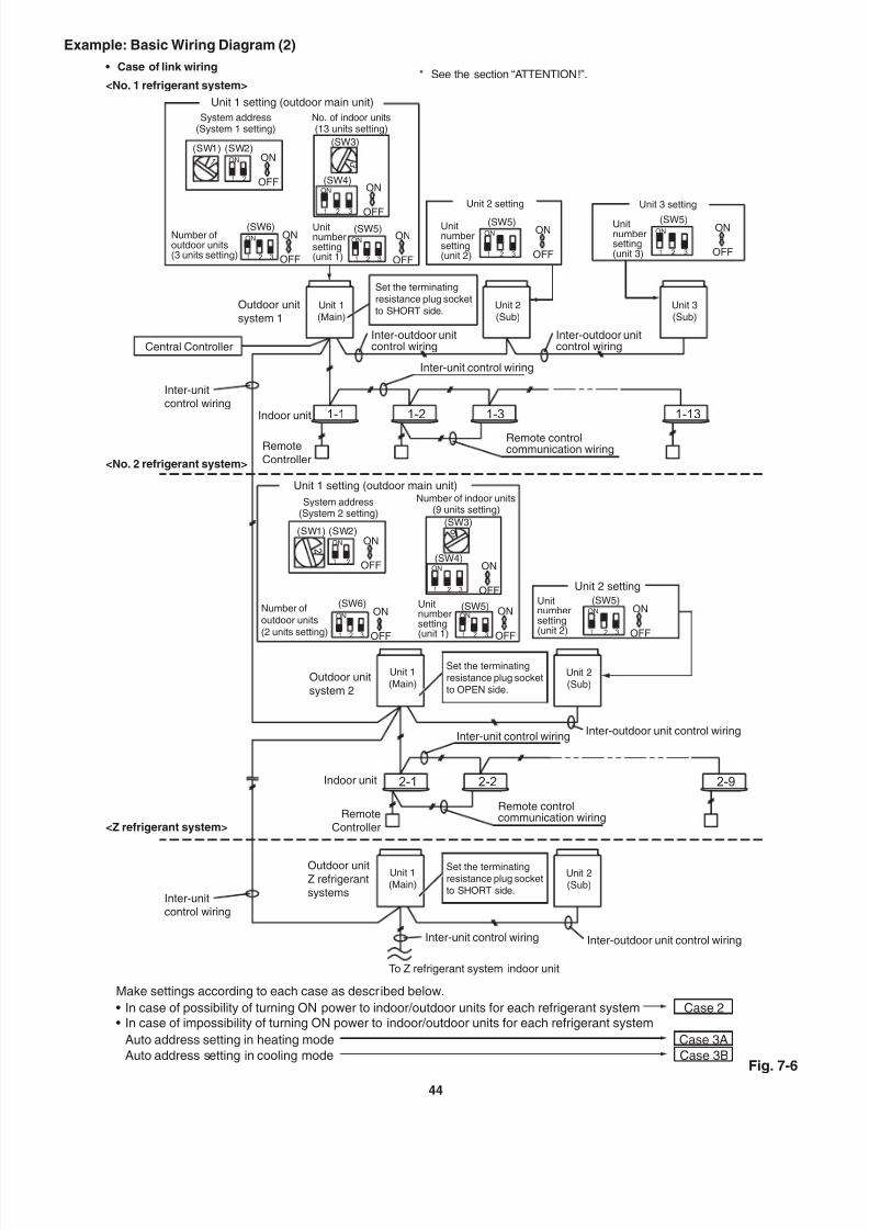
Example: Basic Wiring Diagram (2)
• Case of link wiring
<No. 1 refrigerant system>
1-1 1-2 1-131-3
2
3
9
21 3
1 2 3
1 2 3
321
1 2 3
1 2
21 3
1
1 32
1 2
21 3321
2-1 2-2 2-9
<No. 2 refrigerant system>
<Z refrigerant system>
* See the section “ATTENTION!”.
Unit 1 setting (outdoor main unit)
System address(System 1 setting)
No. of indoor units(13 units setting)
Unit 2 setting Unit 3 setting
Unit 3(Sub)
Unit 2(Sub)
Unit 1(Main)
(SW1) (SW2)(SW3)
(SW4)
(SW6) (SW5)(SW5) (SW5)
ON
ON
ONON ON
ON
ON
ON
ONON ON
ON
OFF
OFF
OFFOFF OFF
OFF
Number ofoutdoor units(3 units setting)
Unitnumbersetting(unit 1)
Unitnumbersetting(unit 2)
Set the terminatingresistance plug socketto SHORT side.
Unitnumbersetting(unit 3)
Inter-outdoor unitcontrol wiring
Inter-outdoor unitcontrol wiring
Remote controlcommunication wiring
Outdoor unitsystem 1
Inter-unitcontrol wiring
Inter-unitcontrol wiring
RemoteController
Indoor unit
Inter-unit control wiring
Central Controller
Unit 1 setting (outdoor main unit)
System address(System 2 setting)
Number of indoor units(9 units setting)
(SW1) (SW2)(SW3)
(SW4)
(SW6) (SW5)
ON
ON
ONON
ON
ON
ONON
OFF
OFF
OFFOFF
Number ofoutdoor units(2 units setting)
Unitnumbersetting(unit 1)
Unit 2 setting(SW5)
ON ON
OFF
Unitnumbersetting(unit 2)
Unit 2(Sub)
Unit 2(Sub)
Unit 1(Main)
Unit 1(Main)
Set the terminatingresistance plug socketto OPEN side.
Set the terminatingresistance plug socketto SHORT side.
Outdoor unitsystem 2
Outdoor unitZ refrigerantsystems
Inter-outdoor unit control wiring
Inter-outdoor unit control wiring
To Z refrigerant system indoor unit
Inter-unit control wiring
Inter-unit control wiring
Remote controlcommunication wiringRemote
Controller
Indoor unit
Fig. 7-6
Make settings according to each case as described below.
• In case of possibility of turning ON power to indoor/outdoor units for each refrigerant system Case 2• In case of impossibility of turning ON power to indoor/outdoor units for each refrigerant system
Auto address setting in heating mode Case 3A Auto address setting in cooling mode Case 3B

7/25/2019 Ex 2 Way Installation
http://slidepdf.com/reader/full/ex-2-way-installation 46/5745
Case 2 In case of possibility of turning ON power to indoor/outdoor units for each refrigerant system:
l In case of possibility of turning ON power to indoor/outdoor units for each refrigerant system:
Indoor unit address setting can be made without starting the compressor.
How to control auto address setting from outdoor unit
1. Set the unit number setting switch (SW5) on unit 1 (outdoor main unit) control P.C. board to:2 31
ON
(Unit 1: This unit becomes to the outdoor main unit.)
Set the unit number setting switch (SW5) on unit 2 control P.C. board to:321
ON
Set the unit number setting switch (SW5) on unit 3 control P.C. board to:321
ON
2. Regarding the number of outdoor units, set the Dip switch (SW6) for setting the number of outdoor units on outdoor main unit
control P.C. board to 3 units.1 2 3
ON ON
OFF
3. Check that the refrigerant system address Rotary switch (SW1) on outdoor main unit control P.C. board in 1 refrigerant system is
set to “1” and the Dip switch (SW2) is set to “0” (at shipment).1 2
ON ON
OFF
4. Regarding the number of indoor units connected to the outdoor unit, set the Dip switch (SW4) for setting the number on indoor
units on outdoor main unit control P.C. board to “1”2 31
ON ON
OFF
and set the Rotary switch (SW3) to “3”.
Total of 13 units installation are made.
5. Turn ON power to all indoor and outdoor units in one refrigerant system.
6. Short circuit the A.ADD pin (CN30) of outdoor main unit for over 1 second long and then open circuit.
(Communication for auto address setting begins.)
* To cancel, again short circuit the A.ADD pin (CN30) for over 1 second long and then open circuit.
LEDs 1 and 2 that indicate auto address setting is in progress go out and that process is stopped.
Be sure to perform auto address setting again.
(Auto address setting is completed when the compressor stops and LEDs 1 and 2 on outdoor main unit control P.C. board goout.)
7. Turn ON power to indoor and outdoor units only for another refrigerant system and repeat steps 1 to 5 described above.
Complete auto address setting for each refrigerant system.
8. Remote control operation is now available.
* When performing auto address setting by the remote controller, perform auto address setting by the remote controller after
step 5.
l Refer to section “Auto Address Setting by Remote Controller.”
7/25/2019 Ex 2 Way Installation
http://slidepdf.com/reader/full/ex-2-way-installation 47/57
7/25/2019 Ex 2 Way Installation
http://slidepdf.com/reader/full/ex-2-way-installation 48/57
7/25/2019 Ex 2 Way Installation
http://slidepdf.com/reader/full/ex-2-way-installation 49/5748
Display During Auto Address Setting
l On the surface of outdoor unit control P.C. board
1 2LED
Blinks alternately
* Do not short circuit the A.ADD pin (CN30) again during auto address setting.
LEDs 1 and 2 go out and address setting is interrupted.
* When auto address setting is normally completed, both LEDs 1 and 2 go out.
In other cases, correct settings referring to the following table and perform auto address setting again.
l Contents of LEDs 1 and 2 on outdoor unit control P.C. board
: Illuminating
: Blinking
: Go out
LED 1 LED 2 Contents of display
After turned ON power (not during auto address setting), it is entirely impossible to communicate with the indoorunit in the system.
After turned ON power (not during auto address setting), although the indoor units more than 1 unit in the systemare recognized, there are inconsistencies between the number of indoor units and setting number of indoor units.
Under auto address settingAlternately
Auto address setting completed
There are inconsistencies between the number of indoor units and setting number of indoor units.
(at the time of auto address setting)Simultaneously
Refer to section “Self-Diagnosis Function Table and Contents of Alarm Display.”Alternating
l Display of remote controller
Blinking “ ” indicator
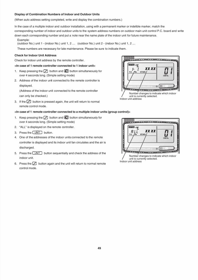
7/25/2019 Ex 2 Way Installation
http://slidepdf.com/reader/full/ex-2-way-installation 50/57

7/25/2019 Ex 2 Way Installation
http://slidepdf.com/reader/full/ex-2-way-installation 51/57
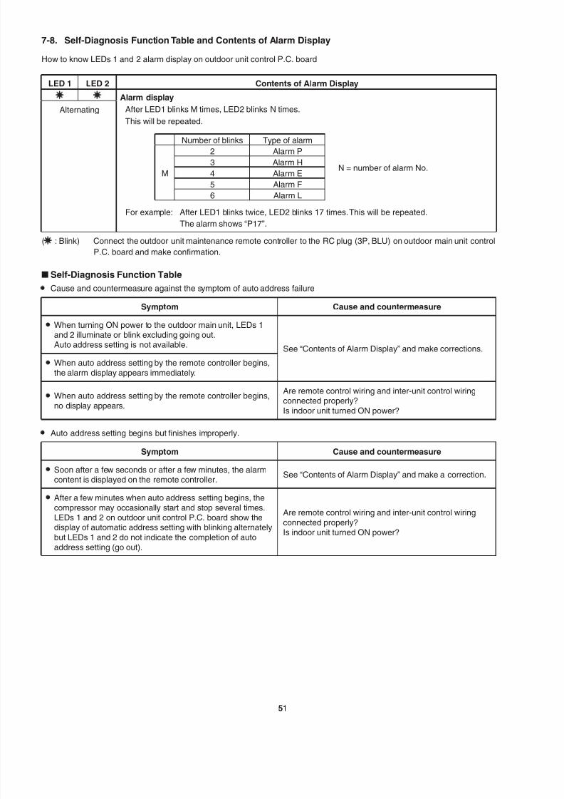
7/25/2019 Ex 2 Way Installation
http://slidepdf.com/reader/full/ex-2-way-installation 52/57
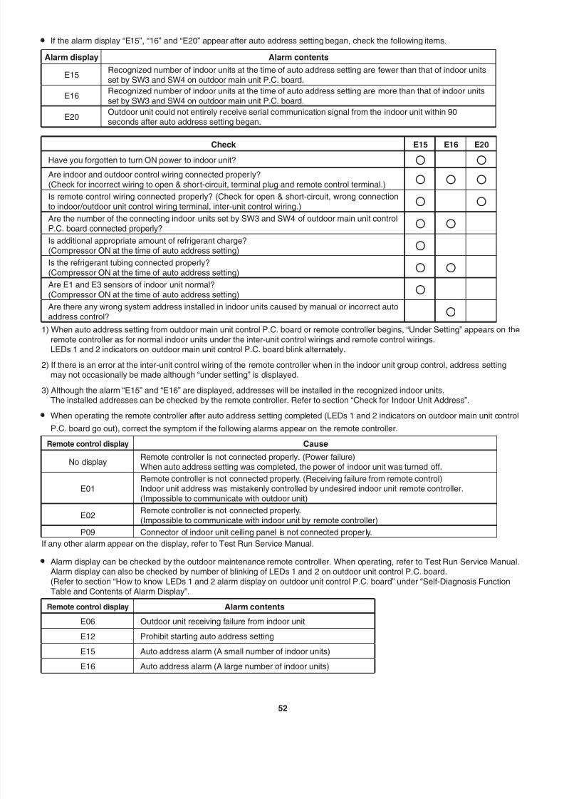
7/25/2019 Ex 2 Way Installation
http://slidepdf.com/reader/full/ex-2-way-installation 53/5752
• If the alarm display “E15”, “16” and “E20” appear after auto address setting began, check the following items.
Alarm display Alarm contents
E15Recognized number of indoor units at the time of auto address setting are fewer than that of indoor units
set by SW3 and SW4 on outdoor main unit P.C. board.
E16Recognized number of indoor units at the time of auto address setting are more than that of indoor units
set by SW3 and SW4 on outdoor main unit P.C. board.
E20Outdoor unit could not entirely receive serial communication signal from the indoor unit within 90seconds after auto address setting began.
Check E15 E16 E20
Have you forgotten to turn ON power to indoor unit?
Are indoor and outdoor control wiring connected properly?
(Check for incorrect wiring to open & short-circuit, terminal plug and remote control terminal.)
Is remote control wiring connected properly? (Check for open & short-circuit, wrong connection
to indoor/outdoor unit control wiring terminal, inter-unit control wiring.)
Are the number of the connecting indoor units set by SW3 and SW4 of outdoor main unit control
P.C. board connected properly?
Is additional appropriate amount of refrigerant charge?
(Compressor ON at the time of auto address setting)
Is the refrigerant tubing connected properly?
(Compressor ON at the time of auto address setting)
Are E1 and E3 sensors of indoor unit normal?
(Compressor ON at the time of auto address setting)
Are there any wrong system address installed in indoor units caused by manual or incorrect auto
address control?
1) When auto address setting from outdoor main unit control P.C. board or remote controller begins, “Under Setting” appears on the
remote controller as for normal indoor units under the inter-unit control wirings and remote control wirings.LEDs 1 and 2 indicators on outdoor main unit control P.C. board blink alternately.
2) If there is an error at the inter-unit control wiring of the remote controller when in the indoor unit group control, address settingmay not occasionally be made although “under setting” is displayed.
3) Although the alarm “E15” and “E16” are displayed, addresses will be installed in the recognized indoor units.The installed addresses can be checked by the remote controller. Refer to section “Check for Indoor Unit Address”.
• When operating the remote controller after auto address setting completed (LEDs 1 and 2 indicators on outdoor main unit controlP.C. board go out), correct the symptom if the following alarms appear on the remote controller.
Remote control display Cause
No displayRemote controller is not connected properly. (Power failure)When auto address setting was completed, the power of indoor unit was turned off.
E01Remote controller is not connected properly. (Receiving failure from remote control)Indoor unit address was mistakenly controlled by undesired indoor unit remote controller.
(Impossible to communicate with outdoor unit)
E02Remote controller is not connected properly.(Impossible to communicate with indoor unit by remote controller)
P09 Connector of indoor unit ceiling panel is not connected properly.
If any other alarm appear on the display, refer to Test Run Service Manual.
• Alarm display can be checked by the outdoor maintenance remote controller. When operating, refer to Test Run Service Manual.Alarm display can also be checked by number of blinking of LEDs 1 and 2 on outdoor unit control P.C. board.
(Refer to section “How to know LEDs 1 and 2 alarm display on outdoor unit control P.C. board” under “Self-Diagnosis Function
Table and Contents of Alarm Display”.
Remote control display Alarm contents
E06 Outdoor unit receiving failure from indoor unit
E12 Prohibit starting auto address setting
E15 Auto address alarm (A small number of indoor units)
E16 Auto address alarm (A large number of indoor units)
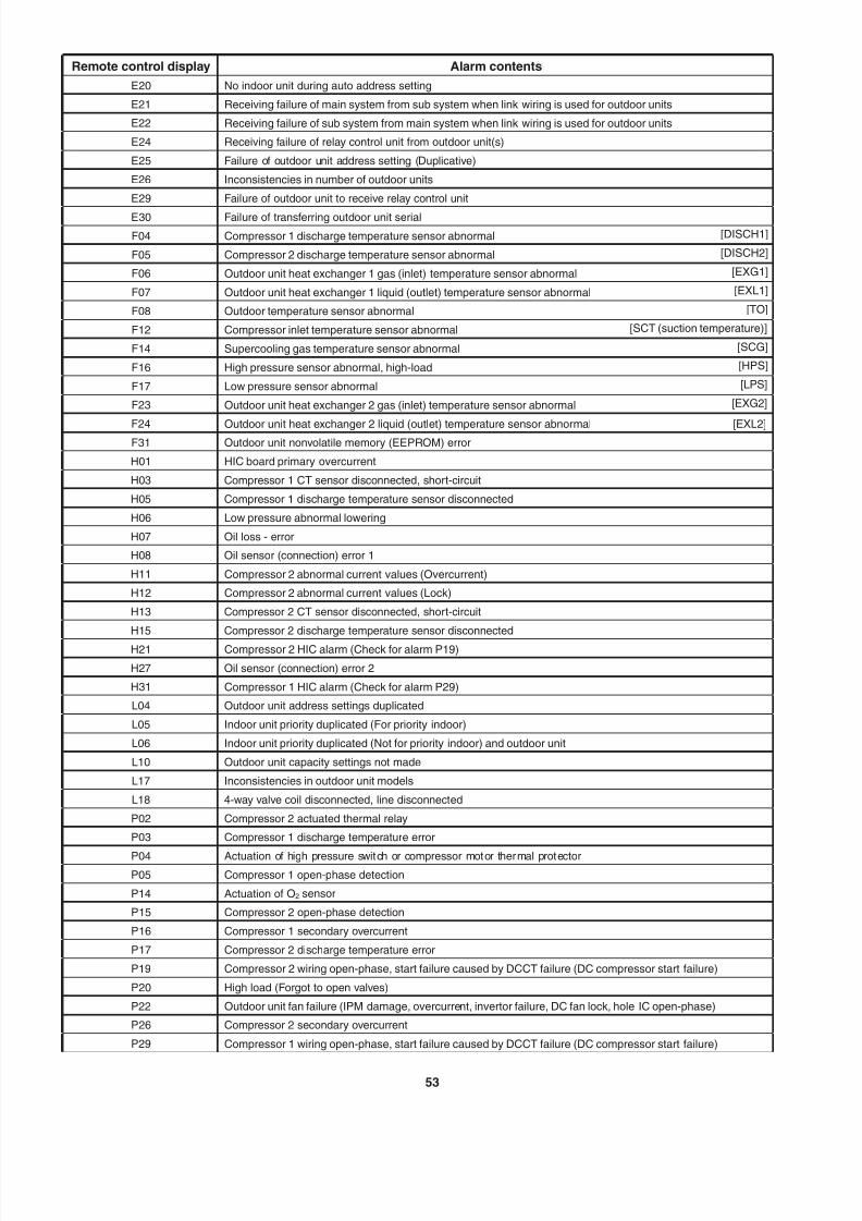
7/25/2019 Ex 2 Way Installation
http://slidepdf.com/reader/full/ex-2-way-installation 54/5753
Remote control display Alarm contents
E20 No indoor unit during auto address setting
E21 Receiving failure of main system from sub system when link wiring is used for outdoor units
E22 Receiving failure of sub system from main system when link wiring is used for outdoor units
E24 Receiving failure of relay control unit from outdoor unit(s)
E25 Failure of outdoor unit address setting (Duplicative)
E26 Inconsistencies in number of outdoor units
E29 Failure of outdoor unit to receive relay control unit
E30 Failure of transferring outdoor unit serial
F04 Compressor 1 discharge temperature sensor abnormal [DISCH1]
F05 Compressor 2 discharge temperature sensor abnormal [DISCH2]
F06 Outdoor unit heat exchanger 1 gas (inlet) temperature sensor abnormal [EXG1]
F07 Outdoor unit heat exchanger 1 liquid (outlet) temperature sensor abnormal [EXL1]
F08 Outdoor temperature sensor abnormal [TO]
F12 Compressor inlet temperature sensor abnormal [SCT (suction temperature)]
F14 Supercooling gas temperature sensor abnormal [SCG]
F16 High pressure sensor abnormal, high-load [HPS]
F17 Low pressure sensor abnormal [LPS]
F23 Outdoor unit heat exchanger 2 gas (inlet) temperature sensor abnormal [EXG2]
F24 Outdoor unit heat exchanger 2 liquid (outlet) temperature sensor abnormal [EXL2]F31 Outdoor unit nonvolatile memory (EEPROM) error
H01 HIC board primary overcurrent
H03 Compressor 1 CT sensor disconnected, short-circuit
H05 Compressor 1 discharge temperature sensor disconnected
H06 Low pressure abnormal lowering
H07 Oil loss - error
H08 Oil sensor (connection) error 1
H11 Compressor 2 abnormal current values (Overcurrent)
H12 Compressor 2 abnormal current values (Lock)
H13 Compressor 2 CT sensor disconnected, short-circuit
H15 Compressor 2 discharge temperature sensor disconnected
H21 Compressor 2 HIC alarm (Check for alarm P19)
H27 Oil sensor (connection) error 2
H31 Compressor 1 HIC alarm (Check for alarm P29)
L04 Outdoor unit address settings duplicated
L05 Indoor unit priority duplicated (For priority indoor)
L06 Indoor unit priority duplicated (Not for priority indoor) and outdoor unit
L10 Outdoor unit capacity settings not made
L17 Inconsistencies in outdoor unit models
L18 4-way valve coil disconnected, line disconnected
P02 Compressor 2 actuated thermal relay
P03 Compressor 1 discharge temperature error
P04 Actuation of high pressure switch or compressor motor thermal protector
P05 Compressor 1 open-phase detection
P14 Actuation of O2 sensor
P15 Compressor 2 open-phase detection
P16 Compressor 1 secondary overcurrent
P17 Compressor 2 discharge temperature error
P19 Compressor 2 wiring open-phase, start failure caused by DCCT failure (DC compressor start failure)
P20 High load (Forgot to open valves)
P22 Outdoor unit fan failure (IPM damage, overcurrent, invertor failure, DC fan lock, hole IC open-phase)
P26 Compressor 2 secondary overcurrent
P29 Compressor 1 wiring open-phase, start failure caused by DCCT failure (DC compressor start failure)
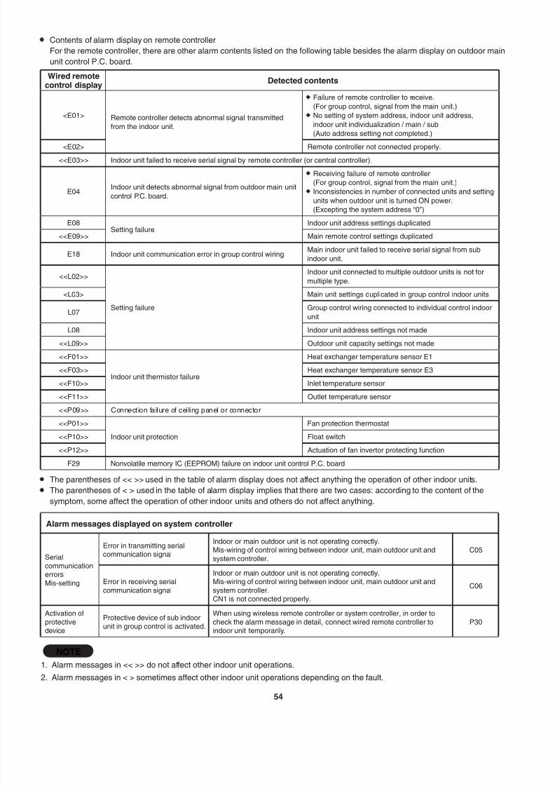
7/25/2019 Ex 2 Way Installation
http://slidepdf.com/reader/full/ex-2-way-installation 55/57

7/25/2019 Ex 2 Way Installation
http://slidepdf.com/reader/full/ex-2-way-installation 56/5755
ATTENTION!
Adjustment of terminating resistance (plug) is necessary.
Communication failure will occur unless adjustment is made correctly.
• Terminating resistance (plug) is mounted on outdoor unit control P.C. board.
• When connecting central controller, interface or peripheral equipment, adjustment of terminating resistance (plug) is necessary.
Although the connection is not made, confirmation is necessary for VRF systems.
• In the case of a refrigerant system, the terminating resistance (plug) for this inter-unit control wiring (S-LINK wiring) is one
location (Refer to section “7-5. Auto Address Setting”).
For 2 or more refrigerant systems, 2 locations should be valid (“SHORT” for VRF systems at shipment). (Refer to section
“7-5. Auto Address Setting”)
In order to make 2 locations valid, let the terminating resistance (plug) of the nearest outdoor unit and the farthest outdoor unit
be valid (SHORT side) from the location of central controller.
In other refrigerant systems excepting 2 locations described above, make them invalid (OPEN side).
It is prohibited making more than 3 locations of terminating resistance valid.
• Since the use of linking the sub outdoor units of VRF systems is not connected to the inter-unit control wiring, it is not necessary
to make the terminating resistance invalid “OPEN side”.
Make final confirmation regarding the central controller or interface & inter-unit control wiring (S-LINK wiring) connected to the
peripheral equipment.
Measure the line resistance with a tester and check whether the values are in the range of 30Ω - 120Ω.
If the resistance values are out of range, check again the terminating resistance.
Nevertheless, if the values are out of range, the problem comes from wiring.
• Is the connection properly made?
• Are there any scratches or damages on the coated surface?
• Measure the line, between wires and ground with the 500V megger (insulation
resistance meter) and check the values are over 100MΩ.
• When measuring, be sure to remove both edges of the wire from the terminal board.
If not removed, it will be damaged.
• If the line resistance is within 100MΩ, newly carry out the wiring work.
Megger
Line
Between wires and ground
(Wire)
(Wire)
(Wire)
(Wire)
(Ground)

7/25/2019 Ex 2 Way Installation
http://slidepdf.com/reader/full/ex-2-way-installation 57/57