ews370ap/ews371ap/ews870ap/ews871ap - … · table of contents. 4 ... multicast/unicast conversion...
TRANSCRIPT

User Manual
Business Solutions
Dual Band Wireless AC2600 Managed Access Point
EWS370AP/EWS371AP/EWS870AP/EWS871APversion 1.0

2
IMPORTANT
To install this Access Point please refer to the Quick Installation Guide included in the product packaging.

3
Chapter 1 Product Overview............................................... 4 Key Features/Introduction........................................................ 5 System Requirements............................................................... 6 Package Contents......................................................................... 7 TechnicalSpecifications..............................................................8 Physical Interface (EWS370AP/EWS371AP).................... 10 Physical Interface(EWS870AP/EWS871AP)....................11
Chapter 2 Before You Begin................................................. 12 Computer Settings....................................................................... 13 Hardware Installation (EWS370AP/EWS371AP)............... 17 Hardware Intallation (EWS870AP/EWS871AP).............. 18 Mounting the AP (EWS370AP/EWS371AP)........................ 19 MountingtheAP(EWS870AP/EWS871AP)........................22Chapter 3 Configuring Your Access Point......................... 25 Default Settings./Web Configuration................................ 26Chapter 4 Building a Wireless Network........................... 27 AccessPointMode......................................................................28Chapter 5 Status.................................................................... 29 Main Status..................................................................................... 30 Connection...................................................................................... 33Chapter 6 Network .............................................................. 34 Basic IPv4/IPv6 Settings.......................................................... 35 Spanning Tree Protocol Setting............................................. 35
Chapter 7 2.4 GHz/5 GHz Wireless....................................... 37 WirelessSettings...........................................................................38 BandSteering................................................................................38 2.4 GHz/5 GHz Wireless Network........................................... 40 2.4GHz/5GHzSSIDProfile......................................................41
Wireless Security.......................................................................... 42 WirelessTrafficShaping...........................................................44 Wireless MAC Filtering............................................................... 45 WPS Mixed-Enterprise................................................................ 46 Fast Roaming................................................................................. 46 Guest Network Settings............................................................ 47
Chapter 8 Management ........................................................ 48 Management VLAN Settings.................................................. 49 Advanced Settings....................................................................... 50 CLI Settings/Email Alert............................................................. 51 Time Zone........................................................................................ 53 Auto Reboot Settings................................................................ 54 Wi-Fi Scheduler............................................................................... 55 Tools.................................................................................................. 56 Account/Firmware........................................................................ 59 Backup/Restore ............................................................................. 60 Log.................................................................................................... 62 Logout/Reset................................................................................. 63Appendix................................................................................. 64 FCC Interference Statement................................................... 65 CE Interference Statement...................................................... 66
Table of Contents

4
Chapter 1 Product Overview
5
Maximum data rates are based on IEEE 802.11 standards. Actual throughput and range may vary depending on many factors including environmental conditions, distance between devices, radio interference in the operating environment, and mix of devices in the network. Features and specifications subject to change without notice. Trademarks and registered trademarks are the property of their respective owners. For United States of America: Copyright © 2016 EnGenius Technologies, Inc. All rights reserved.
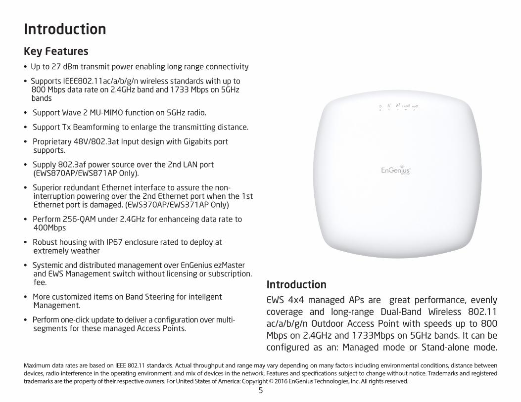
Key Features• Upto27dBmtransmitpowerenablinglongrangeconnectivity
• SupportsIEEE802.11ac/a/b/g/nwirelessstandardswithupto800Mbpsdatarateon2.4GHzbandand1733Mbpson5GHz bands
• SupportWave2MU-MIMOfunctionon5GHzradio.
• SupportTxBeamformingtoenlargethetransmittingdistance.
• Proprietary48V/802.3atInputdesignwithGigabitsport supports.
• Supply802.3afpowersourceoverthe2ndLANport(EWS870AP/EWS871APOnly).
• SuperiorredundantEthernetinterfacetoassurethenon- interruption powering over the 2nd Ethernet port when the 1st Ethernetportisdamaged.(EWS370AP/EWS371APOnly)
• Perform256-QAMunder2.4GHzforenhanceingdatarateto 400Mbps
• RobusthousingwithIP67enclosureratedtodeployat extremely weather
• SystemicanddistributedmanagementoverEnGeniusezMaster and EWS Management switch without licensing or subscription. fee.
• MorecustomizeditemsonBandSteeringforintellgent Management.
• Performone-clickupdatetodeliveraconfigurationovermulti- segments for these managed Access Points.
Introduction
Introduction EWS 4x4 managed APs are great performance, evenly coverage and long-range Dual-Band Wireless 802.11ac/a/b/g/nOutdoorAccessPointwith speeds up to800Mbps on 2.4GHz and 1733Mbps on 5GHz bands. It can be configured as an: Managed mode or Stand-alone mode.

6
These APs are designed to operate in a variety of indoor or outdoor environments. Its high-powered, long-range characteristics make it a cost-effective alternative to ordinary Access Points that don’t have the range and reach to connect to a growing number of wireless users who wish to connect to a business network. The AP supports the 2.4GHz frequency band under 802.11 b/g/n modewhileatthesametimeproviding5GHzbandunder802.11ac/a/n mode for communicating to and from 5GHz capable computers,tabletsorsmartphonesortransferringfiles.
To protect sensitive data during wireless transmissions, the device offers different encryption settings for wireless transmissions, including industry standard WPA and WPA2 encryption.ThedevicealsoincludesMACaddressfilteringto allow network administrators to offer network access only to known computers and other devices based on their MAC addresses.
System Requirements
The following are the Minimum System Requirements in ordertoconfigurethedevice.
• ComputerwithanEthernetinterfaceorwirelessnetworkcapability
• WindowsOS(XP,Vista,7,8,10),MacOS,orLinux-basedoperatingsystems
• Web-BrowsingApplication(i.e.:Edge,InternetExplorer,Firefox,Safari,or
another similar browser application)

7
Package Contents
*EWS370AP/EWS371AP should contain the following items
• AccessPoint
• PowerAdapter(12V/2A)
• CeilingMountBase(9/16”T-Rail)
• CeilingMountBase(15/16”T-Rail)
• MountingKit
• QuickInstallationGuide
• 4detachable5dBi2.4GHzOmni-directionalAntennas(EWS371AP)
• 4detachable5dBi5GHzOmni-directionalAntennas(EWS371AP)
*(allitemsmustbeinpackagetoissuearefund):
*EWS870AP/EWS871AP should contain the following items
• AccessPoint
• PowerAdapter(48V/1.25A)
• PoEinjector
• Groundcable
• WallMountingKit
• PoleMountingKit
• WallMountScrewSet
• MountingScrew&Bolts
• QuickInstallationGuide
• 2detachable5dBi2.4GHzOmni-directionalAntennas(EWS871AP)
• 2detachable7dBi5GHzOmni-directionalAntennas(EWS871AP)
*(allitemsmustbeinpackagetoissuearefund):
8
Operation ModesManaged ModeAccess Point Mode Exquisite RF ManagementBackgorund ScanningAuto Transmit PowerAuto Channel SelectionFastRoaming(802.11K)Band Steering RSSI ThresholdACKtimeout(SupportonEWS870AP/EWS871AP)
Optimize PerformanceQualityofService(QoS):Follow802.11ePowerSaveMode(UAPSD)Pre-Authentication(Compliancewith802.11i&x)PMKCahcing(Compliancewith802.11i)FastRoaming(802.11r)Multicast/UnicastConversion
Easy to Management
BSSIDMultiple SSIDsGuest NetworkVLAN TagVLAN Per SSIDManagement VLANCaptive Portal (Support on Manged mode)
Standard:IEEE802.11ac/a/non5GHzIEEE802.11b/g/non2.4GHz
Antenna
IntegratedOmni-directionalantennas EWS370AP:3dBifor2.4GHz;3dBifor5GHz EWS870AP:3dBifor2.4GHz;3dBifor5GHzExternalOmni-directionalantennas EWS371AP:2x5dBi2.4GHzOmnidirectionalantennas2x5dBi5GHzOmni-directionalAntennas EWS871AP:2x5dBi2.4GHzOmnidirectionalantennas2x7dBi5GHzOmni-directionalAntennasPhysical Interfaces2 x 10/100/1000 Gigabit Ethernet Port with PoE support LAN1Port:802.3at/Proprietary48Vinput LAN2Port:*EWS370AP/EWS371AP:DataTransmission*EWS870AP/EWS871AP:802.3afPSEoutput
LED IndicatorsPowerLAN 1LAN 22.4 GHz5 GHz
Power Requirements802.3at/Proprietary48VinputSupport802.3afPSEoutputwhenusingincludedadapterontheEWS870AP/EWS871AP
Technical Specifications

9
Finger Printing (support on Managed Mode)TrafficShapingPeruser/PerclientMAC Address FilteringE-Mail AlertSaveConfigurationasUsersDefaultWi-Fi Scheduler (Support on Managed mode)SNMP V1/V2c/V3MIB I/II, Private MIBClients StatisticsRADIUSAccounting
Comprehensive ProtectionWireless encryption standardHidden SSID in beaconsRogue AP Detection (Support on Manged mode)L2 IsolationClient IsolationHttpsSSH tunnel
SecurityWEPEncryption-64/128/152bitWPA/WPA2 Personal (WPA-PSK using TKIP or AES)WPA/WPA2 Enterprise (WPA-PSK using TKIP or AES)Hides SSID in beaconsMACaddressfiltering,upto64MACsperSSIDWireless STA (Client) connection listHttps SupportSSH Support
Physical/Environment ConditionsOperating: Temperature:-20°Cto70°C(-4°Fto158°F) Humidity(non-condensing):90%orlessStorage: Temperature:-30°Cto80°C(-22°Fto176°F) Humidity(non-condensing):90%orless

10
Physical Interface (EWS370AP/EWS371AP)Dimensions and WeightsLength:215mm(8.46”)Width:215mm(8.46”)Depth:56mm(2.2”)Weight:1.7Kg(3.7lbs)
1 RP-SMA connectos: Support to install included 3dBi 2.4GHz and 5GHz antennason EWS371AP only.
2 Reset Button: Push this button to reset or reboot this device
3 LAN Port 1 (Proprietary 48V-54V/802.3at):EthernetportforRJ-45cable.
4 LAN Port 2 : EthernetportforRJ-45cable.
5 DC-Jack: Power from the included DC12V/2A adapter
6 LED Indicators: LED lights for Power, LAN Port 1, LAN Port 2, 2.4 GHz Connection and 5 GHz Connection.
1
5 2
6
4 3
6
11
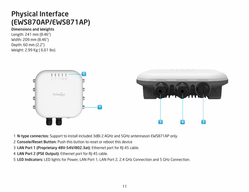
Physical Interface (EWS870AP/EWS871AP)Dimensions and WeightsLength:241mm(8.46”)Width:209mm(8.46”)Depth:60mm(2.2”)Weight:2.99Kg(6.61lbs)
1 N-type connectos: Supporttoinstallincluded3dBi2.4GHzand5GHzantennasonEWS871APonly.
2 Console/Reset Button: Push this button to reset or reboot this device
3 LAN Port 1 (Proprietary 48V-54V/802.3at):EthernetportforRJ-45cable.
4 LAN Port 2 (PSE Output): EthernetportforRJ-45cable.
5 LED Indicators: LED lights for Power, LAN Port 1, LAN Port 2, 2.4 GHz Connection and 5 GHz Connection.
5
1
23 4

12
Chapter 2 Before You Begin

13
Windows XP/Windows 7/Windows 8/Windows 10
InordertousetheAccessPoint,youmustfirstconfigurethe
TCP/IPv4connectionofyourWindowsOScomputersystem.
1a. Click the Start button and open the Control Panel
1b. Move your mouse to the lower right hot corner to
display the Charms Bar and select the Control Panel in
Windows 8 OS.
1c. In Windows 10, click Start to select All APPs to enter
the folder of Windows system for selecting Control Panel.
Computer Settings
Windows XP Windows 7
Windows 8
Windows 10

14
2a. In Windows XP, click Network Connections.
2b. In Windows 7/Windows 8/Windows 10, click View Network Status and Tasks in the Network and Internet section, then select Change adapter settings.
3. Right click on Local Area Connection and select Properties.
4. Select Internet Protocol Version 4 (TCP/IPv4) and then
select Properties.
5. Select Use the following IP address and enter an IP
address that is different from the Access Point and Subnet
mask, then click OK.

15
Note: Ensure that the IP address and Subnet mask are
on the same subnet as the device.
Forexample:ENH220EXTIPaddress:192.168.1.1
PCIPaddress:192.168.1.2–192.168.1.255
PCSubnetmask:255.255.255.0
16
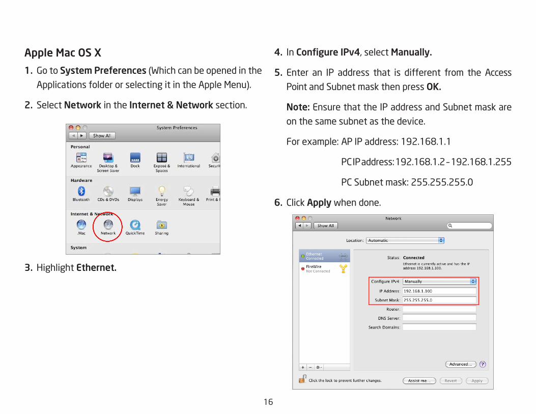
Apple Mac OS X
1. Go to System Preferences (Which can be opened in the
Applications folder or selecting it in the Apple Menu).
2. Select Network in the Internet & Network section.
3. Highlight Ethernet.
4. In Configure IPv4, select Manually.
5. Enter an IP address that is different from the Access
Point and Subnet mask then press OK.
Note: Ensure that the IP address and Subnet mask are
on the same subnet as the device.
Forexample:APIPaddress:192.168.1.1
PCIPaddress:192.168.1.2–192.168.1.255
PCSubnetmask:255.255.255.0
6. Click Apply when done.

17
1. Connect one end of the Ethernet cable into the LAN port
of the Access Point and the other end to the Ethernet
port on the computer.
2. Connect the Power Adapter to the DC-IN port of the
Access Point and plug the other end into an electrical
outlet.
3. Screw on the provided antennas to the top of this device.
(EWS371AP only)
Thisdiagramdepictsthehardwareconfiguration.
Note: TheAccessPointsupportsbothIEEE802.3atPoE(Power over Ethernet) or the included power adapter.
You may use either one as the power source. DO NOT use both at the same time.
1
Hardware Installation (EWS370AP/EWS371AP)
1
2

18
1. Connect one end of the Ethernet cable into the 1st
LAN(PoE) port of the AP and the other end to the AP
EthernetportonthePoEinjector.
2. Connect the Power Adapter to the DC-IN port of the PoE
injectorandplugtheotherendintoanelectricaloutlet.
3. Connect the second Ethernet cable into the LAN port of
thePoEinjectorandtheotherendtotheEthernetport
on the computer.
4. Place the pane removed from step A back into the
device.
6. Screw on the provided antennas to the top of this device.
(EWS871APonly)
Thisdiagramdepictsthehardwareconfiguration.
Note: This Access Point supports both 802.3at PoE(Power over Ethernet) or the included injector and
adapter. You may use either one as the power source.
Do not use both at the same time.
4
Hardware Installation (EWS870AP/EWS871AP)
1
4
3
2

19
Mounting the AP (EWS370AP/EWS371AP)
Usingtheprovidedhardware,theAPcanbeattachedtoawalloraceiling.
1. Managed Indoor Access Point
2. Power Adapter 3. RJ-45 Ethernet Cable
4. Ceiling Mount Base (9/16” T-Rail)
5. Ceiling Mount Base (15/16” T-Rail)
6. Mounting Screw Kit
7. 2.4GHz Detachable
Antenna x 4 (EWS371AP only)
8. 5GHz Detachable
Antenna x 4 (EWS371AP only)

20
To attach the AP on a ceiling
1. Slide the ceiling mount base into the slot of the Access
Point.
2. Hold the Access Point with one hand to reach the other
hand overthe T-Rail sides of the bracket. Then hook the
stationary end of the ceiling mount bracket onto the
T-Rail.
1 2

21
To attach the AP on a wall
1. Determine where the Access Point to be placed and mark
locationonthesurfaceforthetwomountingholes.Use
theappropriatedrillbittodrilltwo8.1mmdiagramand
26mm depth holes in the markings and hammer the bolts
into the openings.
2. Screw theanchors into theholesuntil theyareflushwith the wall.
3. Screw the included screws into the anchors.

22
Mounting the AP (EWS870AP/EWS871AP)
Usingtheprovidedhardware,theAPcanbeattachedtoawallorapole.
1. Managed Outdoor Access Point 2. PoE Injector 3. PoE Injector
4. Ground cable 5. Wall Mounting Kit 6. Pole Mounting Kit
7. Quick Installation Guide 8. Mounting Screws & Bolts 8. 2.4GHz&5GHz Detachable Antennas

23
To attach this AP on a wall
1. Mark the four locations of the mounting holes on the
flatmountingsurface..
2. Drilla37mmdeep8mmholeinthemarkingsandhammer the bolts into the openings.
3.Placethelockandflatwasheronthefourhexcap
screws and drive these screws to attach bracket of this
Access Point.
4. Attach this device onto the wall by tightening the bolt’s
flatwashersandnutstosecurethemountingbaseto
the mounting surface31
2 4

24
To attach this AP on a pole
1. Drive the four round head screws to attached the pole
mount bracket to the wall mount bracket.
2. Thread the open end of the pole straps through these
two tabs on the pole mount bracket.
3. Lock and tighten pole strap to secure this pole mount
bracket to the pole.
1
2
3

25
Chapter 3 Configuring Your Access Point

26
This sectionwill show you how to configure the device
usingtheweb-basedconfigurationinterface.
Default Settings
Please use your Ethernet port or wireless network adapter to connect the Access Point.
IP Address 192.168.1.1Username / Password admin / admin
Web Configuration
1. Openawebbrowser(InternetExplorer/Firefox/Safari/Chrome) and enter the IP Address http://192.168.1.1
Note: If you have changed the default LAN IP Address of
the Access Point, ensure you enter the correct IP Address.
2. The default username and password are admin.
Once you have entered the correct username and
password, click the Login button to open the web-base
configurationpage.
* The model will be varied by different models.
3. If successful,youwillbe logged inandsee theUserMenu of this Access Point.
Configuring Your Access Point

27
Chapter 4 Building a Wireless Network

28
Access Point ModeInAccessPointMode,APbehaveslikesacentralconnectionforstationsorclientsthatsupportIEEE802.11ac/a/b/g/nnetworks.ThestationsandclientsmustbeconfiguredtousethesameSSID(ServiceSetIdentifier)andsecuritypasswordtoassociate
with the AP. The AP supports up to eight SSIDs per band at the same time for secure access.
APAccess Point
Client
Client Client
Client Client
Client2.4 GHz 5 GHz

29
Chapter 5 Status

30
Save Changes
This page lets you save and apply the settings shown under Unsaved changes list, or Revert the unsaved changes and
revert to the previous settings that were in effect.
Device Status
Clicking the Device Status link under the Overview menu shows the status information about the current operating
mode.
• The Device Information section shows general system information such as Device Name, MAC Address, Current Time, Firmware Version, and Management VLAN ID
Note: VLAN ID is only applicable in Access Point, WDS
AP or WDS BR mode.
• The Memory Information section shows usage of memory such as Total Available, Free, Cached, Buffered
Overview

31
• The LAN Information section shows the Local Area Network settings such as the LAN IP Address, Subnet mask, Primary DNS Address, Secondary DNS Address, status of DHCP client, and status of Spanning Tree
protocol (STP).
The Wireless LAN Information 2.4 GHz/5 GHz section shows wireless information such as Operation Mode,Frequency, and Channel. Since this Access Point supports multiple-SSIDs, information about each SSID, the ESSID, and security settings, are displayed
Note: ProfileSettingsareonlyapplicableinAccessPointand WDS AP modes.
• TheStatistics section shows Mac information such as SSID,MACaddress,RXandTX.

32
2.4 GHz/5 GHz Connection List
ClicktheconnectionlinkundertheOverviewmenudisplays
the connection list of clients associated to the AP’s 2.4
GHz/5 GHz, along with the MAC addresses and signal
strength for each client. Clicking Refresh updates the
client list.
Note: Only applicable in Access Point and WDS APmodes.
2.4 GHz/5 GHz WDS Link List
Click the connection link under the Overviewmenu. This
page displays the current status of the WDS link, including
WDS Link ID, MAC Address, Link Status and RSSI.
Note: OnlyapplicableinWDSAPandWDSBridgemodes.
Realtime
TheRealtimesectioncontainsthefollowingoptions:
CPU Loading: 3 minutes CPU loading percentageinformation, it displays current loading, average loading
andpeakloadingstatus.Leftbarisloadingpercentage;
button is time tracing. Interval is every 3 seconds
Connections Realtime

33
Traffic Loading: 2.4GHz and 5GHz and Ethernet port
inboundandoutboundtrafficbycurrent,averageand
peak time.
Realtime Connection (Pkts): Overview on currentactivenetworkconnections. ItdisplaysUDPandTCP
packetsinformationandotherconnectionstatus.UDP
connectionscurve is inblue;TCPconnectioncurve is
ingreen;otherscurveisinred.Belowofchartshows
connections source and destination.

34
Chapter 6 Network

35
IPv4/IPv6 Settings
This page allows you to modify the device’s IP settings.
IP Network Settings: Select whether the device IP address
willuseastaticIPaddressspecifiedintheIPaddressfield
or be obtained automatically when the device connects to
a DHCP server.
IP Address: The IP address of this device.
Subnet Mask: The IP Subnet mask of this device.
Gateway: The Default Gateway of this device. Leave it
blank if you are unsure of this setting.
Primary/Secondary DNS: The primary/secondary DNS
address for this device.
Save: Click Savetoconfirmthechanges.
Spanning Tree Protocol (STP) Settings
This page allows you to modify the Spanning Tree settings. Enabling the Spanning Tree protocol will prevent network
loops in your LAN network.
Spanning Tree Status:EnablesorDisablestheSpanningTree function. Default is Disable.
Hello Time: SpecifiesBridgeHelloTime in seconds.Thisvalue determines how often the device sends handshake
packets to communicate information about the topology
throughout the entire Bridged Local Area Network.
Max Age: SpecifiesBridgeMaxAgeinseconds.Ifanother
Basic

36
bridge in the spanning tree does not send a hello packet for
a long period of time, it is assumed to be inactive.
Forward Delay:SpecifiesBridgeForwardDelayinseconds.Forwarding delay time is the time spent in each of the
Listening and Learning states before the Forwarding state
is entered. This delay is provided so that when a new bridge
comesontoabusynetwork,itanalyzesdatatrafficbefore
participating in the network.
Priority: SpecifiesthePriorityNumber.Asmallernumberhas a greater priority than a larger number.
Save: Click Savetoconfirmthechanges.

37
Chapter 7 2.4 GHz & 5 GHz Wireless

38
Wireless Settings
Device Name: Enter a name for the device. The name you
type appears in SNMP management. This name is not the
SSID and is not broadcast to other devices.
Band Steering: Enable Band Steering to send802.11nclientstothe5GHzband,where802.11b/gclientscannot
go,andleave802.11b/gclientsin2.4GHztooperateat
their slower rates. Before implementing this feature, we
suggest you to assure the both 2.4GHz and 5GHz SSID,
as welll as security settings must be the same. EnGenius
Band Steering supports following advanced settings,
*Force 5GHz:WhenbandsteeringisconfiguredtoForce5GHz mode, the AP will not dual band capable client
devices to network to the 2.4GHz band only if the client
devices are not currently associated on 2.4GHz radio in
this AP.
*Prefer 5GHz:WhenbandsteeringisconfiguredtoPrefer5GHz mode, the AP will steer dual band capable client
devices to 5GHz radio when the RSSI value of these client
devices on 5GHz radio is more than set one. The allowed
RSSI value for default setting is -75dBm.
*Band Balance: When band steering is configured toBand Balance mode, the AP will steer dual band capable
client devices to 5GHz when the RSSI value of these client
devices on 5GHz radio is more than set one. To evenly
allocate RF resource on the both 2.4GHz and 5GHz radios,
users also can set the portion of client devices on 5GHz
radio to assure smoothly connection. The default value of
the5GHzradiois75%.
Save: Click Savetoconfirmthechanges.
Wireless

39
This page displays the current status of the Wireless
settings of this AP.
2.4 GHz/5 GHz Wireless Network
Operation Mode: EWS 4x4 devices support Access Point
currently.
Wireless Mode: Scrow down this list to select wireless
broadcasting standard on 2.4GHz and 5GHz frequency
bands.
Channel HT Mode: Scrow down this list to select bandwidth
for operating under a frequency band. The default channel
bandwidth is 20 MHz on 2.4GHz frequency radio and 40
MHz on 5GHz frequency radio. Considering the different
applications, users can decide to implement a channel
bandwidthtofulfillrealapplications.Thelargerthechannel,
the greater the transmission quality and speed.
Transmit Power (Tx Power): Default Tx power is Auto
to obey regulartory power of each country.
Channel: Click Configuration button to open a new
windows to configure channels for performing wireless
service.
*Default configuration: Default setting of channelselection is “All” to perform auto channel on the existchannel list.

40
*None:Click“None”todisablethesettingonthisradio.This radio is disabled.
*Group Configuration:Clickspecificgroupsofchannelsfor performing auto channel function. For example, users
canclickU-NII-1andU-NII-3toperformautochannelon
these bands; the mechanism of this AP will select the
relatively optimal channel to peform wireless service.
Data Rate: Select a data rate from the drop-down list. The
data rate affects throughput of data in the AP. Select the
best balance for you and your network but note that the
lower the data rate, the lower the throughput, though
transmission distance is also lowered.
RTS/CTS Threshold:Specifiesthethresholdpackagesizefor RTC/CTS. A small number causes RTS/CTS packets to be
sent more often and consumes more bandwidth.
Client Limits: Limits the total number of clients on this radio.
Oncesettingtheceilingofclientnumbers,themaximum
assocaited client devices will be restricted at this number.
Aggregation: Integrate multiple data packets into one
packet to deliver to client devices. This option reduces the
number of packets, but also increases packet sizes.
AP Detection: AP Detection can select the best channel to
use by scanning nearby areas for Access Points.
Distance: Specifies the distance betweenAccess Pointsand client devices. The proper setting for this parameter
may assist Access Points to avoid the improper operation
whentransmittingdataunderafiledapplication.
* The Distance setting should be supported on the outdoor
Access Point including EWS870AP and EWS871AP.
Save: Click SavetoconfirmthechangesorCancel to cancel
and return to previous settings.

41
2.4 GHz/5 GHz SSID Profile
Current Profile: You can configure up to sixteen (16)different SSIDs (eight (8) per band). If multiple client
devices will be accessing the network, you can arrange the
devices into SSID groups. Click Edittoconfiguretheprofileand check whether you want to enable extra SSID.
SSID:SpecifiestheSSIDforthecurrentprofile.
Suppressed SSID: Check this option to hide the SSID from
clients. If checked, the SSID will not appear in the site survey.
Station Separation: Click the appropriate radio button to
allow or prevent communication between client devices.
VID:SpecifiestheVLANtagforeachprofile.Ifyournetowrkincludes VLANs, you can specify a VLAN ID for packets pass
through the Access Point with a tag.
Wireless Security: See the Wireless Security section.
Isolation: Restrict clients communicating with different
VIDs by selecting the radio button.
Save: Click Save to accept the changes.
42
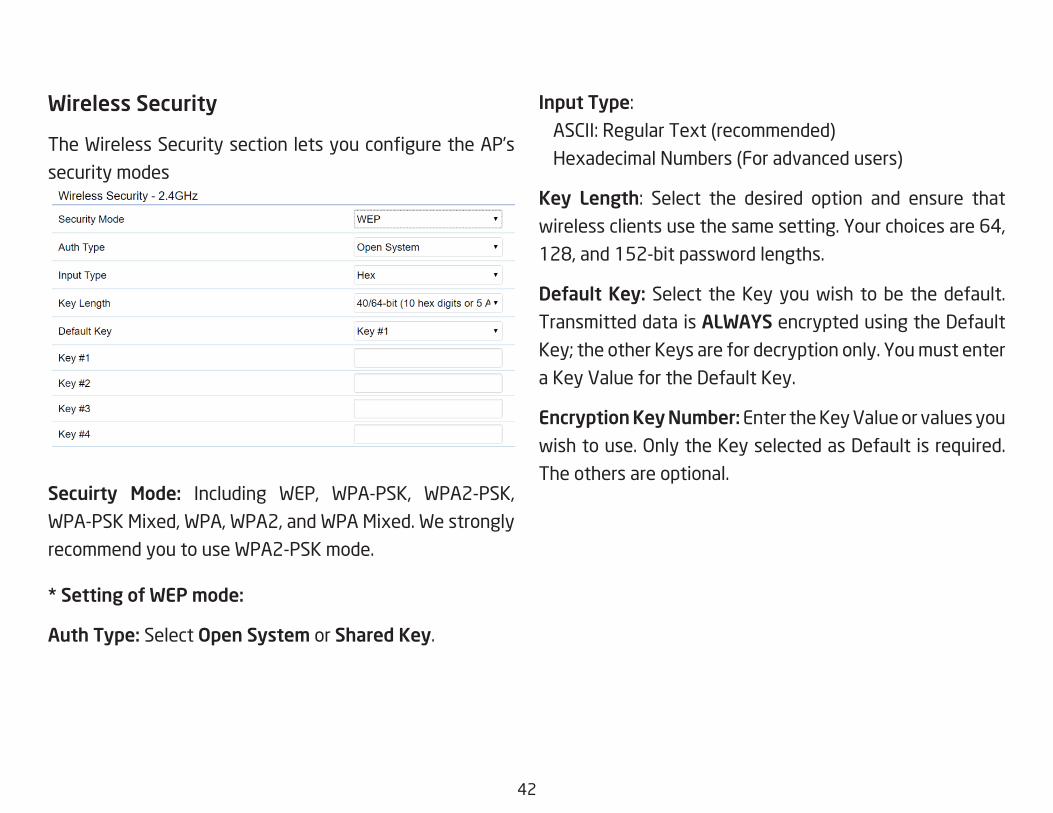
Wireless Security
TheWirelessSecuritysectionletsyouconfiguretheAP’s
security modes
Secuirty Mode: Including WEP, WPA-PSK, WPA2-PSK,
WPA-PSK Mixed, WPA, WPA2, and WPA Mixed. We strongly
recommend you to use WPA2-PSK mode.
* Setting of WEP mode:
Auth Type: Select Open System or Shared Key.
Input Type: ASCII:RegularText(recommended)
Hexadecimal Numbers (For advanced users)
Key Length: Select the desired option and ensure thatwireless clients use the same setting. Your choices are 64,
128,and152-bitpasswordlengths.
Default Key: Select the Key you wish to be the default.
Transmitted data is ALWAYS encrypted using the Default
Key;theotherKeysarefordecryptiononly.Youmustenter
a Key Value for the Default Key.
Encryption Key Number: Enter the Key Value or values you
wishtouse.OnlytheKeyselectedasDefaultisrequired.
The others are optional.

43
* Setting of WPA-PSK, WPA2-PSK and WPA-PSK Mixed (Pre-Shared Key):
Encryption:YoumayselectAES,TKIPorBoth(TKIP+AES)to be the encryption type you would like. Please ensure
that your wireless clients use the same settings.
Passphrase: Wireless clients must use the same Key to
associate the device. If using ASCII format, the Key must
befrom8to63charactersinlength.IfusingHEXformat,
theKeymustbe64HEXcharactersinlength.
Group Key Update Interval: Specifies how often, inseconds, the Group Key changes. The default value is 3600.
*
* Setting of WPA-Enterprise & WPA2-Enterprise (Pre-Shared Key):
Encryption: Select the WPA encryption type you would like.
Please ensure that your wireless clients use the same settings.
Radius Server: Enter the IP address of the Radius server.
Radius Port: Enter the port number used for connections
to the Radius server.

44
Radius Secret: Enter the secret required to connect to the
Radius server.
Radius Accounting: Enable or disable accounting feature.
Radius Accounting Server: Enter the IP address of the
Radius accounting server.
Radius Accounting Port Enter the port number used for
connections to the Radius accounting server.
Radius Accounting Secret: Enter the secret required toconnect to the Radius accounting server.
Interim Accounting Interval: Specifies how often, inseconds, the accounting data sends.
Note: 802.11n does not allow WEP/WPA-PSK TKIP/WPA2-PSK TKIP security mode. The connection mode
willautomaticallychangefrom802.11nto802.11g.
45
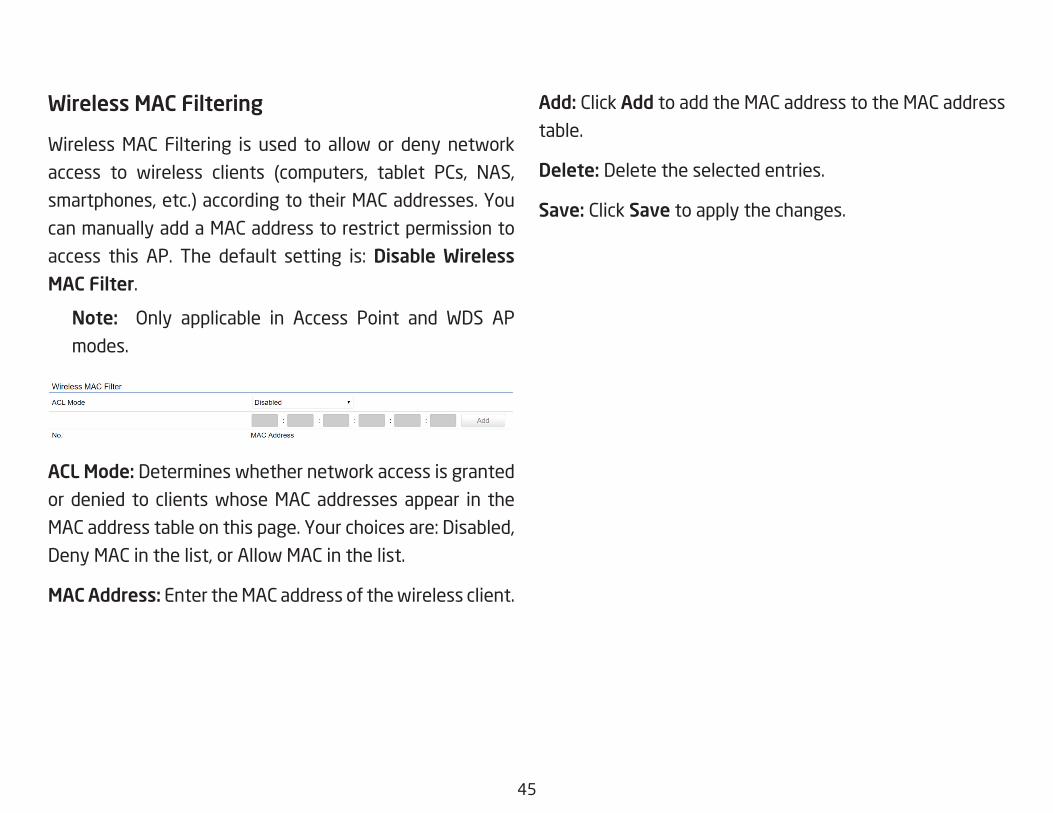
Wireless MAC Filtering
Wireless MAC Filtering is used to allow or deny network
access to wireless clients (computers, tablet PCs, NAS,
smartphones, etc.) according to their MAC addresses. You
can manually add a MAC address to restrict permission to
access this AP. The default setting is:Disable Wireless MAC Filter.
Note: Only applicable in Access Point and WDS APmodes.
ACL Mode: Determines whether network access is granted
or denied to clients whose MAC addresses appear in the
MACaddresstableonthispage.Yourchoicesare:Disabled,
Deny MAC in the list, or Allow MAC in the list.
MAC Address: Enter the MAC address of the wireless client.
Add: Click Add to add the MAC address to the MAC address
table.
Delete: Delete the selected entries.
Save: Click Save to apply the changes.

46
Wireless AdvancedWireless Traffic Shaping
Trafficshaping regulates theflowofpackets leavingan
interfacetodeliverimprovedQualityofService.
Enable Traffic Shaping:Defaultisdisable.YoumaycheckthisoptiontoenableWirelessTrafficShapingperSSID.
Download Limit: Specifiesthewirelesstransmissionspeedused for downloading.
Upload Limit: Specifies thewireless transmission speedused for uploading.
Per User: Check this option to enable wireless trafficshaping per user function. This function allow users to limit
the maximum download / upload bandwidth for each client
devices on this SSID.
Save: Click Savetoconfirmthechanges.
Fast Roaming
Enable the function to serve mobile client devices that roam
from Access Point to Access Point. Some applications running
on Client devices require fast re-association when they roam
to a different Access Point
Please enter the settings of the SSID and initialize the Security
mode to WPA enterprise, as well as to set the Radius Server
firstly.UserscanenabletheFastRoamingandimplementthe
advanced search.
Please also set the same enterprise Encryption under
the same SSID on other Access Points and enable the
Fast Roaming. When the configuration is realized on
different Access Point, the mobile client devices can run
the voice service and require seamless roaming to prevent
delay in conversation from Access Point to Access Point.
47
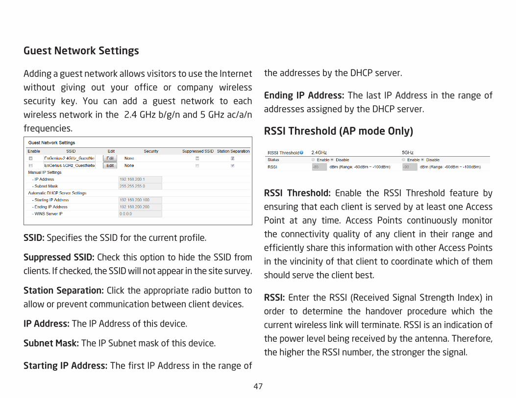
Guest Network Settings
Adding a guest network allows visitors to use the Internet
without giving out your office or company wireless
security key. You can add a guest network to each
wireless network in the 2.4 GHz b/g/n and 5 GHz ac/a/n
frequencies.
SSID:SpecifiestheSSIDforthecurrentprofile.
Suppressed SSID: Check this option to hide the SSID from
clients. If checked, the SSID will not appear in the site survey.
Station Separation: Click the appropriate radio button to
allow or prevent communication between client devices.
IP Address: The IP Address of this device.
Subnet Mask: The IP Subnet mask of this device.
Starting IP Address: ThefirstIPAddressintherangeof
the addresses by the DHCP server.
Ending IP Address: The last IP Address in the range of
addresses assigned by the DHCP server.
RSSI Threshold (AP mode Only)
RSSI Threshold: Enable the RSSI Threshold feature by
ensuring that each client is served by at least one Access
Point at any time. Access Points continuously monitor
the connectivity quality of any client in their range and
efficientlysharethisinformationwithotherAccessPoints
in the vincinity of that client to coordinate which of them
should serve the client best.
RSSI: Enter the RSSI (Received Signal Strength Index) in
order to determine the handover procedure which the
current wireless link will terminate. RSSI is an indication of
the power level being received by the antenna. Therefore,
the higher the RSSI number, the stronger the signal.

48
Chapter8 Management
49
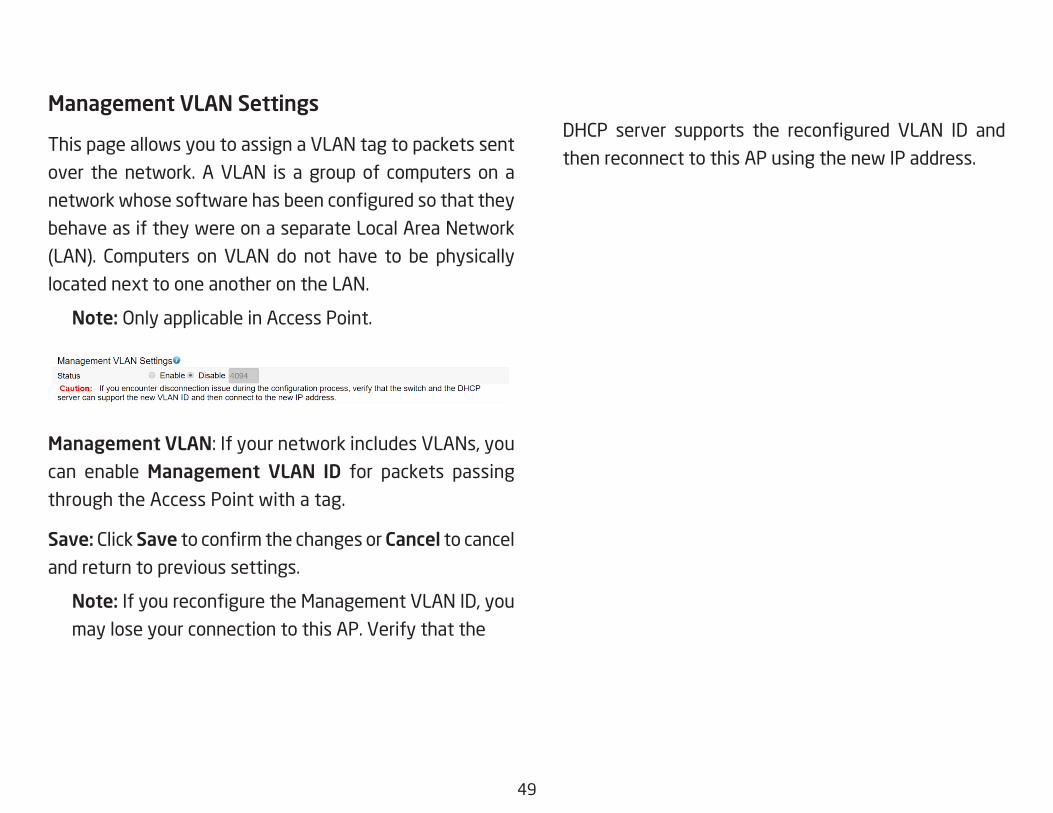
Management VLAN Settings
This page allows you to assign a VLAN tag to packets sent
over the network. A VLAN is a group of computers on a
networkwhosesoftwarehasbeenconfiguredsothatthey
behave as if they were on a separate Local Area Network
(LAN). Computers on VLAN do not have to be physically
located next to one another on the LAN.
Note: OnlyapplicableinAccessPoint.
Management VLAN:IfyournetworkincludesVLANs,youcan enable Management VLAN ID for packets passing
through the Access Point with a tag.
Save: Click SavetoconfirmthechangesorCancel to cancel
and return to previous settings.
Note: IfyoureconfiguretheManagementVLANID,youmay lose your connection to this AP. Verify that the
DHCP server supports the reconfigured VLAN ID and
then reconnect to this AP using the new IP address.

50
SNMP Settings
This page allows you to assign the Contact Details, Location,
Community Name, and Trap Settings for a Simple Network
Management Protocol (SNMP). SNMP is a networking
management protocol used to monitor network attached
devices. SNMP allows messages (called protocol data units)
tobesenttovariouspartsofthenetwork.Uponreceiving
these messages, SNMP compatible devices (called agents)
returns the data stored in their Management Information
Bases.
SNMP Enable/Disable:EnablesordisablestheSNMPfeature.
Contact: Specifiesthecontactdetailsofthedevice.Location: Specifiesthelocationofthedevice.
Community Name (Read Only): Specifiesthepasswordfor the SNMP community for read only access.
Community Name (Read/Write):Specifiesthepasswordfor the SNMP community with read/write access.
Trap Destination Address:SpecifiestheIPaddressofthecomputer that will receive the SNMP traps.
Trap Destination Community Name: Specifiesthepassword for the SNMP trap community.
SNMPv3: Enables or disables the SNMPv3 feature.
User Name:SpecifiestheusernameforSNMPv3.
Auth Protocol:Selectstheauthenticationprotocoltype:MDS or SHA.
Auth Key: Specifiestheauthenticationkey.
Priv Protocol:Selectstheprivacyprotocoltype:DES.
Advanced Settings

51
Priv Key: Specifiestheprivacykeyforprivacy.
Engine ID: SpecifiestheengineIDforSNMPv3.
Apply Save: Click Apply Save to apply the changes.
CLI Settings
CLI:TheCommandLineInterface(CLI)allowsyoutotypecommands instead of choosing them from a menu or
selecting an icon.
SSH:EnableSecureShell(SSH)tomakesecure,encryptedconnections in the network. Secure Shell is a network
protocol that allows data to be exchanged using a secure
channel between two network devices.
HTTPS: Enable HTTPS to transfer and display web content
securely. The Hypertext Transfer Protocol over SSL (Secure
Socket Layer) is a TCP/IP protocol used by web servers to
transfer and display web content securely.
Email Alert
You can use the Email Alert feature to send messages
to the configured email addresswhen particular system
events occur.
Note:DoNOT use your personal email address as it can
unnecessarily expose your personal email login credentials.
Useaseparateemailaccountmadeforthisfeatureinstead
Status: Enable this function for further settings.
From: Enter the email address to show the sender of the
email.
To: Enter the address to receive email alerts.

52
Subject: Enterthetexttoappearintheemailsubjectline.
Username: Enter the username for the email account that
will be used to send emails.
Password: Enter the password for the email account that
will be used to send emails.
SMTP Server: Enter the IP address or hostname of the
outgoing SMTP server.
Port: Enter the SMTP port number to use for outbound
emails.

53
Time Setting
This page allows you to set the internal clock of the AP. Manually Set Date and Time: Manually specify the
date and time.
Synchorize with PC:ClickthisbuttontosynchorizeDate and time of this AP with the PC.
Automatically Get Date and Time: Select
Automatically Get Date and Time and check whether
you wish to enter the IP address of an NTP server or
use the default NTP server to have the internal clock
set automatically.
Time Zone: Choose a time zone to implement the
service for this AP.
Enable Daylight Saving:Checkwhetherdaylightsavings applies to your area.
Start:Selecttheday,month,andtimewhendaylightsavings time starts.
Enable Daylight Saving:Selecttheday,month,andtimewhen daylight savings times ends.
Time Zone

54
Auto Reboot Settings
You can specify how often you wish to reboot the AP.
Auto Reboot Setting: Enables or disables the AutoReboot function.
Timer:Selectthedayandenterthetimeyouwouldliketo reboot automatically.
Save:ClickSave to apply the changes.

55
Wi-Fi Scheduler
The Wi-Fi Scheduler can be created for use in enforcing
rules. For example, if you wish to restrict web access to
Mon-Fri from 3pm to 8pm, you could create a schedule
selecting Mon, Tue, Wed, Thu and Fri while entering a Start
timeof3pmandEndTimeof8pmtolimitaccesstothese
times.
Status: Enables or disables the Wi-Fi scheduler function.
Wireless Radio: Select 2.4 GHz or 5 GHz from the drop-
down list for the preferred band type.
SSID Selection: Select a SSID from the drop-down list.
Schedule Templates: Select a schedule template from the
drop-down list.
Day(s): Place a checkmark in the boxes for the desired days
or select the All Week radio button to select all seven days
of the week.
Duration:TheStartTimeisenteredintwofields.Thefirstbox is for hours and the second box is for minutes. The End
Time is entered in the same format as the Start time.

56
Ping Test Parameters
This page allows you to analyze the connection quality
of the AP and trace the routing table to a target in the
network.
Target IP: Enter the IP address you would like to search.
Ping Packet Size: Enter the packet size of each ping.
Number of Pings: Enter the number of times you wish to
ping.
Start Ping: Click Start Ping to begin pinging the target
device (via IP).
Traceroute Target: Enter the IP address or domain name
you wish to trace.
Start Traceroute: Click Start Traceroute to begin the trace
route operation.
Tools

57
Speed Test Parameters / LED Control
This page allows you to implement speed test to realize
thethroughputofatargetDUT.
Target IP / Domain Name: Enter an IP address or domain
name you wish to impelement a speed test for realizing
the variance on wireless speed.
Time Period: Enter the time in seconds that you would like
the test to implement for and in how many intervals.
IPv4/IPv6 Port: ThisAccessPointsuses IPv45001andIPv6 5002 port for the speed test.
Start:Clickstarttoimplementspeedtest.
LED Control
Control LED on/off for Power, LAN interface, or 2.4 GHz/5
GHz WLAN interface.
Power: Enables or disables the Power LED indicator.
LAN: Enables or disables the LAN LED indicator.
WLAN-2.4 GHz: Enables or disables the WLAN-2.4 GHz LED
indicator.
WLAN-5 GHz: Enables or disables the WLAN-5 GHz LED
indicator.

58
Device Discovery
This page allows you to discover devices from network
forOperationMode,IPAddress,SystemMACAddressand
Firmware version.
59
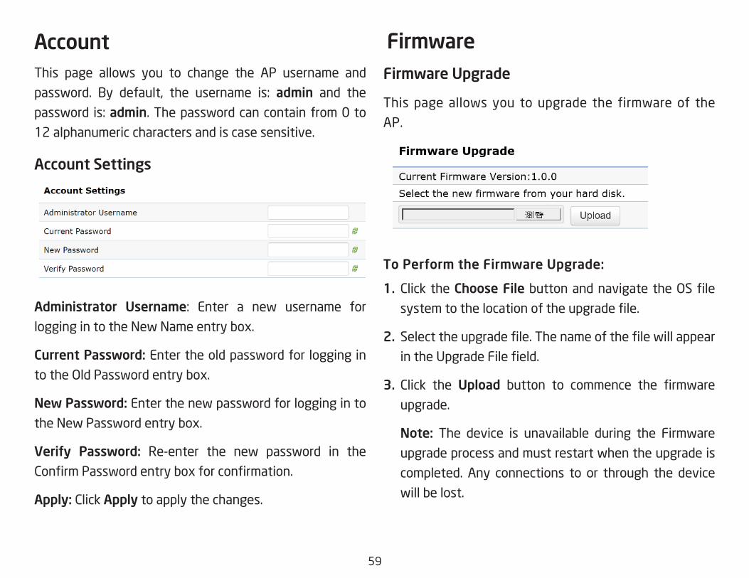
This page allows you to change the AP username and
password. By default, the username is: admin and the
passwordis:admin. The password can contain from 0 to
12 alphanumeric characters and is case sensitive.
Account Settings
Administrator Username: Enter a new username forlogging in to the New Name entry box.
Current Password: Enter the old password for logging in
totheOldPasswordentrybox.
New Password: Enter the new password for logging in to
the New Password entry box.
Verify Password: Re-enter the new password in the
ConfirmPasswordentryboxforconfirmation.
Apply: Click Apply to apply the changes.
Firmware Upgrade
This page allows you to upgrade the firmware of the
AP.
To Perform the Firmware Upgrade:
1. Click the Choose FilebuttonandnavigatetheOSfilesystemtothelocationoftheupgradefile.
2. Selecttheupgradefile.ThenameofthefilewillappearintheUpgradeFilefield.
3. Click the Upload button to commence the firmwareupgrade.
Note: The device is unavailable during the Firmware
upgrade process and must restart when the upgrade is
completed. Any connections to or through the device
will be lost.
Account Firmware

60
Backup/RestoreThis page allows you to save the current device
configurations. When you save your configurations,
you also can reload the saved configurations into the
device through the Restore Saved Settings from a file
section. If extreme problems occur, or if you have set
the AP incorrectly, you can use the Reset button in the
Revert to Factory Default Settings section to restore
all the configurations of the AP to the original default
settings.
Backup Setting: Click Export to save the current
configured settings.
Restore New Setting: To restore settings that have
been previously backed up, click Browse, select the
file, and click Restore.
Restore to Default: Click Reset button to restore the
AP to its factory default settings.
61
User Setting
The function allows you to backup the current device
configurations into the AP as the default value. If
extreme problems occur, or if you have set the AP
incorrectly, you can push the Reset button to revert all
the configurations of the AP to the user default.
Back Up Setting as Default: Click Backup to backup
the user settings you would like to the device’s memory
for the default settings.
Restore to User Default:ClickRestore to restore user
settings to the factory standard settings.
Note1: After setting the current settings as the default, you should click the Restore to Default on the
web interface for reverting the settings into the factory default instead of pushing the reset button.
Note2: Please write down your account and password before saving. The user settings will now become
the new default settings at the next successful login.

62
System Log
The AP automatically logs (records) events of possible
interest in its internal memory. To view the logged
information, click the Log link under the System Manager
menu. If there is not enough internal memory to log all
events, older events are deleted from the log. When
powered down or rebooted, the log will be cleared.
Status:Enable/Disablethisfunction.
Log type: You may choose one of log types to display logs
in the following window. The default log types is All.
Remote Log
This page allows you to setup the Remote Log functions
for this AP.
Remote Log:Enable/Disablethisfunction.
Log Server IP Address: Enter the IP address of the log
server.
Apply: Click Apply to apply the changes.
Log

63
Logout
Logout: Click Logout in Management menu to logout.
Pleaseconfirmagaintologoutthesystemornot.
Reset
In some circumstances, it may be required to force the
device to reboot. Click on Reset to reboot the AP.
Onceyouclick resetbutton,youwill seetheoptionsfor
reboot or restore this AP.
Rebootthedevice:Clickittorebootthisdevice.
RestoretoFactoryDefault:Clickittoresetthisdeviceto
factory default setting.
RestoretoUserDefault:Clickittoresetthisdeviceto
user default settings. For realizing the setting method,
you may refer page 65 and page 66.

64
Appendix
65
Federal Communication Commission Interference Statement This equipment has been tested and found to comply with the limits for a Class B digital device, pursuant to Part 15 of the FCC Rules. These limits are designed to provide reasonable protection against harmful interference in a residential installation. This equipment generates, uses and can radiate radio frequency energy and, if not installed and used in accordance with the instructions, may cause harmful interference to radio communications. However, there is no guarantee that interference will not occur in a particular installation. If this equipment does cause harmful interference to radio or television reception, which can be determined by turning the equipment off and on, the user is encouraged to try to correct the interference by one of the following measures:
• Reorientorrelocatethereceivingantenna.
• Increasetheseparationbetweentheequipmentandreceiver.
• Connecttheequipmentintoanoutletonacircuitdifferentfromthattowhichthereceiverisconnected.
• Consultthedealeroranexperiencedradio/TVtechnicianforhelp
FCC Caution:
Any changes or modifications not expressly approved by the party responsible for compliance could void the user’s authority to operate this equipment.
This device complies with Part 15 of the FCC Rules. Operation is subject to the following two conditions: (1) This device may not cause harmful interference, and (2) this device must accept any interference received, including interference that may cause undesired operation.
IMPORTANT NOTE: Radiation Exposure StatementThis equipment complies with FCC radiation exposure limits set forth for an uncontrolled environment. This equipment should be installed and operated with minimum distance 20 cm between the radiator & your body.
Appendix A

66
Europe – EU Declaration of ConformityThisdevicecomplieswiththeessentialrequirementsoftheR&TTEDirective1999/5/EC.ThefollowingtestmethodshavebeenappliedinordertoprovepresumptionofconformitywiththeessentialrequirementsoftheR&TTEDirective1999/5/EC:
• EN60950-1 Safety of Information Technology Equipment
• EN50385 Generic standard to demonstrate the compliance of electronic and electrical apparatus with the basic restrictions related to human exposure
to electromagnetic fields (0 Hz - 300 GHz)
• EN300328 Electromagnetic compatibility and Radio spectrum Matters (ERM); Wideband Transmission systems; Data transmission equipment operating
in the 2,4 GHz ISM band and using spread spectrum modulation techniques; Harmonized EN covering essential requirements under article 3.2 of the R&TTE Directive
• EN301893 Broadband Radio Access Networks (BRAN); 5 GHz high performance RLAN; Harmonized EN covering essential requirements of article 3.2 of
the R&TTE Directive
• EN301489-1 Electromagnetic compatibility and Radio Spectrum Matters (ERM); ElectroMagnetic Compatibility (EMC) standard for radio equipment and
services; Part 1: Common technical requirements
• EN301489-17 Electromagnetic compatibility and Radio spectrum Matters (ERM); ElectroMagnetic Compatibility (EMC) standard for radio equipment and
services; Part 17: Specific conditions for 2,4 GHz wideband transmission systems and 5 GHz high performance RLAN equipment
Appendix B - CE Interference Statement

67
This device is a 5GHz wideband transmission system (transceiver), intended for use in all EU member states and EFTA countries, except in France and Italy where restrictive use applies.
In Italy the end-user should apply for a license at the national spectrum authorities in order to obtain authorization to use the device for setting upoutdoorradiolinksand/orforsupplyingpublicaccesstotelecommunicationsand/ornetworkservices.
This device may not be used for setting up outdoor radio links in France and in some areas the RF output power may be limited to 10 mW EIRP in the frequency range of 2454 – 2483.5 MHz. For detailed information the end-user should contact the national spectrum authority in France.
Česky [Czech] [Jméno výrobce] tímto prohlašuje, že tento [typ zařízení] je ve shodě se základními požadavky a dalšími příslušnými ustanoveními směrnice 1999/5/ES.
Dansk [Danish] Undertegnede [fabrikantens navn] erklærer herved, at følgende udstyr [udstyrets typebetegnelse] overholder de væsentlige krav og øvrige relevante krav i direktiv 1999/5/EF.
Deutsch [German] Hiermit erklärt [Name des Herstellers], dass sich das Gerät [Gerätetyp] in Übereinstimmung mit den grundlegenden Anforderungen und den übrigen einschlägigen Bestimmungen der Richtlinie 1999/5/EG befindet.
Eesti [Estonian] Käesolevaga kinnitab [tootja nimi = name of manufacturer] seadme [seadme tüüp = type of equipment] vastavust direktiivi 1999/5/EÜ põhinõuetele ja nimetatud direktiivist tulenevatele teistele asjakohastele sätetele.
English Hereby, [name of manufacturer], declares that this [type of equipment] is in compliance with the essential requirements and other relevant provisions of Directive 1999/5/EC.
Español [Spanish] Por medio de la presente [nombre del fabricante] declara que el [clase de equipo] cumple con los requisitos esenciales y cualesquiera otras disposiciones aplicables o exigibles de la Directiva 1999/5/CE.
Ελληνική [Greek] ΜΕ ΤΗΝ ΠΑΡΟΥΣΑ [name of manufacturer] ΔΗΛΩΝΕΙ ΟΤΙ [type of equipment] ΣΥΜΜΟΡΦΩΝΕΤΑΙ ΠΡΟΣ ΤΙΣ ΟΥΣΙΩΔΕΙΣ ΑΠΑΙΤΗΣΕΙΣ ΚΑΙ ΤΙΣ ΛΟΙΠΕΣ ΣΧΕΤΙΚΕΣ ΔΙΑΤΑΞΕΙΣ ΤΗΣ ΟΔΗΓΙΑΣ 1999/5/ΕΚ.

68
Français [French] Par la présente [nom du fabricant] déclare que l’appareil [type d’appareil] est conforme aux exigences essentielles et aux autres dispositions pertinentes de la directive 1999/5/CE.
Italiano [Italian] Con la presente [nome del costruttore] dichiara che questo [tipo di apparecchio] è conforme ai requisiti essenziali ed alle altre disposizioni pertinenti stabilite dalla direttiva 1999/5/CE.
Latviski [Latvian] Ar šo [name of manufacturer / izgatavotāja nosaukums] deklarē, ka [type of equipment / iekārtas tips] atbilst Direktīvas 1999/ 5/EK būtiskajām prasībām un citiem ar to saistītajiem noteikumiem.
Lietuvių [Lithuanian] Šiuo [manufacturer name] deklaruoja, kad šis [equipment type] atitinka esminius reikalavimus ir kitas 1999/5/EB Direktyvos nuostatas.
Nederlands [Dutch] Hierbij verklaart [naam van de fabrikant] dat het toestel [type van toestel] in overeenstemming is met de essentiële eisen en de andere relevante bepalingen van richtlijn 1999/5/EG.
Malti [Maltese] Hawnhekk, [isem tal-manifattur], jiddikjara li dan [il-mudel tal-prodott] jikkonforma mal-ħtiġijiet essenzjali u ma provvedimenti oħrajn relevanti li hemm fid-Dirrettiva 1999/5/EC.
Magyar [Hungarian] Alulírott, [gyártó neve] nyilatkozom, hogy a [... típus] megfelel a vonatkozó alapvetõ követelményeknek és az 1999/5/EC irányelv egyéb elõírásainak.
Polski [Polish] Niniejszym [nazwa producenta] oświadcza, że [nazwa wyrobu] jest zgodny z zasadniczymi wymogami oraz pozostałymi stosownymi postanowieniami Dyrektywy 1999/5/EC.
Português [Portuguese] [Nome do fabricante] declara que este [tipo de equipamento] está conforme com os requisitos essenciais e outras disposições da Directiva 1999/5/CE.
Slovensko [Slovenian] [Ime proizvajalca] izjavlja, da je ta [tip opreme] v skladu z bistvenimi zahtevami in ostalimi relevantnimi določili direktive 1999/5/ES.
Slovensky [Slovak] [Meno výrobcu] týmto vyhlasuje, že [typ zariadenia] spĺňa základné požiadavky a všetky príslušné ustanovenia Smernice 1999/5/ES.
Suomi [Finnish] [Valmistaja = manufacturer] vakuuttaa täten että [type of equipment = laitteen tyyppimerkintä] tyyppinen laite on direktiivin 1999/5/EY oleellisten vaatimusten ja sitä koskevien direktiivin muiden ehtojen mukainen.
Svenska [Swedish] Härmed intygar [företag] att denna [utrustningstyp] står I överensstämmelse med de väsentliga egenskapskrav och övriga relevanta bestämmelser som framgår av direktiv 1999/5/EG.