ew installation manual - waterfurnace - smarter from the · pdf file ·...
TRANSCRIPT

IM1469 11/08
Installation Information
Water Piping Connections
Electrical
Startup Procedures
Troubleshooting
Preventive Maintenance
Hydronic Heat Pumps • R-410ARefrigerant • 2thru5Tons
EW
Ins
talla
tion
Man
ual


1
EW INSTALLATION MANUAL
Table of Contents
GeneralInstallationInformation 3
Accessories&OtherOptions 4
UnitDimensions 5
PotableWaterSystems 6-7
Hydronic Section 8
OpenLoopSystems 9
EarthCoupledSystems 10
Electrical 11-12
Schematics 13-16
ExternalControl 17-18
Staging 19-20
ConvertingtoaDedicatedCoolingUnit 21
UnitStartup 22
ControlPanel,Parameters&OperationModes 23-24
CapacityData 25
FlowRates&PressureDrop 26-27
Troubleshooting 28-29
PreventiveMaintenance 30

2
EW INSTALLATION MANUAL
Model Nomenclature
FamilyEW = E Series Hydronic Heat Pumps
Unit Capacity020 MBTUH 1
030 MBTUH042 MBTUH060 MBTUH 3
OperationH = Non-reversibleR = Reversible Voltage
0 = 208-230/60/1 Commercial 3
1 = 208-230/60/1 Residential 3
2 = 265-277/60/1 4
3 = 208-230/60/34 = 460-480/60/3
Desuperheater 2
(Requires accessory pump kit)0 = None2 = Hot Water Generation Without Factory Installed Pump
Non-Standard OptionsS = StandardA-R, T-Z = Nonstandard Options
VintageA = Current
EW 020 H 1 0 SS A
Notes: 1 EW020 vented load coax is standard. 2 Available on 042 and 060 only. 3 EW060 is not rated for 208/60/1 operation. 4 Avaliable on 020 and 030 only.

3
EW INSTALLATION MANUAL
Safety AdvisementsInstallation and servicing of heating and air conditioning equipment can be hazardous due to system pressure and elec-
trical components. Only trained and qualified service personnel should install, repair or service heating and air conditioning equipment.
When working on heating and air conditioning equipment, observe precautions in the literature, tags and labels attached to the unit as well as other safety precautions that may apply, such as the following safety measures:
Follow all safety codes.• Wear safety glasses and work gloves.• Use a quenching cloth for brazing operations.• Have a fire extinguisher available for all brazing operations.•
Moving and StorageMove units in the normal “up” orientation. Do not stack more than two units in total height. When the equipment is
received, all items should be carefully checked against the bill of lading to be sure that all crates and cartons have been received. Examine units from the cartons if necessary. Units in question should also be internally inspected. If any damage is noted, the carrier should make the proper notation on the delivery receipt, acknowledging the damage.
Unit Location Locate the unit in an indoor area that allows easy removal of the access panels and has enough space for service
personnel to perform maintenance or repair. Provide sufficient room to make water and electrical conditions. Units may be stacked vertically in small mechanical rooms. These units are not approved for outdoor installation and, therefore, must be installed inside the structure being conditioned. Do not locate in areas subject to freezing.
PipingBoth source as well as load fluid piping must be at least as large as the unit connections on the heat pump (larger on
long runs).
Process Water ApplicationsFor process water applications, it is recommended that a secondary load heat
exchanger be installed to prevent corrosion to the unit’s primary coaxial coil. In situations where scaling could be heavy or where biological growth such as iron bacteria will be present, a closed loop system is recommended. Over a period of time, ground water unit heat exchanger coils may lose heat exchange capability due to a buildup of mineral deposits. These can be cleaned only by a qualified service mechanic as special pumping equipment and solutions are required. Never use flexible hoses with a smaller inside diameter than that of water connections.
Mounting UnitsUnits should be mounted level on a vibration absorbing pad slightly larger than
the base to provide isolation between the unit and the floor. It is not necessary to anchor the unit to the floor. Allow access to front access panel for servicing com-pressor.
WARNING:Before performing service or maintenance operations on the system, disconnect all power sources to unit. Electrical shock could cause personal injury. Before applying power to the unit, make sure that all panels and screws are in place. Failure to do so could cause risk of electrical shock.
Vibration Absorbing Mesh Pad
Figure 1: Unit Mounting
Safety Considerations
General Installation Information

4
EW INSTALLATION MANUAL
Accessories and Other Options
Water Connection Kits (Field Installed)Water connection kits have been designed to facilitate load-side and loop-side water connections. See IM1470 for more
information.
Earth Loop Pump Kit (Field Installed) A specially designed one or two-pump module provides all liquid flow, fill and connection requirements for independent single unit systems (230/1/60 only). The one-pump module is capable of 20 feet of head at 16.0 GPM, while the two-pump module is capable of 40 feet of head at 16.0 GPM.
Desuperheater (Factory Installed, EW042 and EW060 Only)An optional heat reclaiming desuperheater coil constructed of vented double-wall copper construction suitable for
potable water is available. The coil is factory mounted inside the unit. A DPK5 pump kit is required (field installed), which includes a DHW tank connection and a temperature limit pump shutoff.
Load-side Pump Kit(Field Installed) Load pump kits are available to provide all liquid flow requirements for independent single unit systems (230/1/60 only). For the EW020 a Grundfos UP15-42B7 (part number 24P501A04) is recommended for applications which require low flow. To select the proper pump, be certain that the system pressure drop is calculated correctly. For higher flow applications, a Grundfos UP26-116 (part number EWPK1) is avail-able. Refer to the Pump Curves in Figures 3 to ensure that the application fits under the pump. If the job requirements are out-side the pump curve, an alternate pump will need to be obtained to maintain the neces-sary flow.
Flow Rate GPM (L/s)
Feet
of H
ead
(kPa
)
0 5(0.32)
40 (1119.6)
35 (104.7)
30 (89.7)
20 (59.8)
15 (44.9)
10 (29.9)
25 (74.8)
10(0.63)
15(0.95)
20(1.26)
25(1.58)
30(1.89)
35(2.21)
240501A04
EWPK1
Figure 2: EWPK1 & 240501A04 - Pump Curves
1-1/2˝FPT
1˝ FPT
3/4˝ FPT3/4˝ FPT
Geo Storage Tank
NOTE: Never use piping smaller than 1 inch. Limit length of pipe to 50 feet or less.
TypeLCopperTubeGPM 3/4 1 1-1/4 1-1/2 22 1.53 3.24 5.5 1.45 8.5 2.16 2.9 1.17 3.9 1.48 5.0 1.89 6.1 2.3 0.910 7.5 2.8 1.112 3.9 1.614 5.2 2.116 6.6 2.718 8.2 3.420 10.0 4.1 1.122 5.0 1.325 6.3 1.630 2.235 2.940 3.845 4.750 5.7
TypeLCopperPressureLossFtofHdper100ft
NOTE: Standard piping practice limits pressure drop to 4 ft of hd per 100 ft.

5
EW INSTALLATION MANUAL
Unit Dimensions
From “Geo”1” x 3-3/4” Nipple
To “Geo”1” x 3-3/4” Nipple
30° 30°
3/4” COLD INLET 53” DIP TUBE3/4” HOT OUTLET
W/ SECONDARY ANODE
8”
1-1/4”
HEIGHT
35-3/4”
Optional “From Geo”Connection Shipped with1-1/2” Pipe Plug Installed
T&PVALVE
DIAMETER
5-1/4”
Red Wire attached to Thermistoror Thermostat for Top Exit Control
Element Location
Lower Sensor Thermistor (12P541-01) to be used by Water to Water Units
Optional “To Geo” ConnectionShipped with 1-1/2” Pipe Plug Installed
Lower Thermostat to beused with Synergy Units
PARTNUMBER WATERHEATERMODELNUMBER
GALLONCAPACITY
ELEMENTWATTAGE(240VOLT)
NUMBEROFELEMENTS
RVALUE
DIMENSIONS(inches)
HEIGHT DIAMETER
Geo-Storage - 80 SGV 82 10TS 80 4500 1 16 63-1/4 24
Geo-Storage - 120 SGV 120 10TS 119 4500 1 16 63-1/4 28

6
EW INSTALLATION MANUAL
Potable Water Systems
The EW020 model is designed to provide domestic hot water generation. An optional factory-installed desuperheater coil may be provided with an EW042 and EW060 to assist with this process.
Figure 4: Suggested Domestic Water Heater Hookup
NOTES: 1) Unions and valves must be installed so that acid flushing of the heat exchanger is possible. 2) Route thermistor wires to EW. Remove yellow thermistor wires on TB 3 & 4 from control box and connect
thermistor wires from geothermal storage tank. Set the pump sampling (PS) in the set up of the control board to continuously (C) sampling (reference Note 5 in the Wiring Schematic).
LOAD PUMP
HYDRONICLOAD
Source IN
P/T PortsP/T Ports
Ball Valve
DielectricUnions
DielectricUnions
WaterFurnaceEW042 & EW060
*NOTE: A 30 PSI pressure relief valve(Part No: SRV30) should be used inhydronic applications.
1-1/2˝FPT
ExpansionTank
AirVent
PressureGauge
30 PSIRELIEF VALVE
AirSeparator
TODSH
FROMDSH
Back Flow Preventer /Pressure Relief Valve
Source OUT
GEOSTORAGE
TANK
PUMP
HOT COLD
DOMESTIC

7
EW INSTALLATION MANUAL
Potable Water Systems (cont.)
Figure 5: Alternate Hot Water Installation
P/T PortsP/T Ports
Ball Valve
DielectricUnions
DielectricUnions
WaterFurnaceEW020
WaterFurnaceGEOTANK
1-1/2˝FPT
HOT COLD
LOOP FIELD
FLOW CENTER
NOTES: 1) Unions and valves must be installed so that acid flushing of the heat exchanger is possible. 2) Make sure there is not a check valve in the diptube of the tank. 3) Route thermistor wires to EW. Remove yellow thermistor wires on TB 3 & 4 from control box and connect
thermistor wires from geothermal storage tank. Set the pump sampling (PS) in the set up of the control board to continuously (C) sampling (reference Note 5 in the Wiring Schematic).

8
EW INSTALLATION MANUAL
Synergy3D Thermostat
Be sure to remove the plug in the end of the pump motor (if Grundfos® pumps are used) to allow trapped air to be discharged and to ensure the motor housing has been flooded.
Route thermistor wires to EW. Remove yellow thermistor wires on TB 3 & 4 from control box and connect thermistor wires from geothermal storage tank. Set the pump sampling (PS) in the set up of the control board to continuously (C) sampling (reference Note 5 in the Wiring Schematic).
Adequate rate of flow (GPM) is very important to system performance and long term reliability. Follow the guidelines for recommended flow and pipe sizing in the EW recommendations table.
Hydronic SectionWaterFurnace geothermal storage tank thermostat and thermistor
Yellow thermistor wires connected to TB (3 & 4) on EW control board
EW
LOAD PUMP
HYDRONICLOAD
Source IN
P/T PortsP/T Ports
Ball Valve
DielectricUnions
DielectricUnions
WaterFurnaceEW042 & EW060
*NOTE: A 30 PSI pressure relief valve(Part No: SRV30) should be used inhydronic applications.
1-1/2˝FPT
ExpansionTank
AirVent
PressureGauge
30 PSIRELIEF VALVE
AirSeparator
TODSH
FROMDSH
Back Flow Preventer /Pressure Relief Valve
Source OUT
GEOSTORAGE
TANK
PUMP

9
EW INSTALLATION MANUAL
Open Loop - Well Water Systems Always maintain water pressure in the heat exchanger by placing water control valves at the outlet of the unit. Use a closed bladder type expansion tank to minimize mineral deposits. Ensure proper water flow through the unit by checking pressure drop across the heat exchanger and comparing it to the figures in the capacity data tables in the specification catalog. Normally, about 2 GPM flow rate per ton of cooling capacity is needed in open loop systems, (1.5 GPM per ton minimum if entering source temperature is above 50°F [10°C]. Some water control valves draw their power directly from the unit’s 24V transformer and can overload and possibly burn out the transformer. Check total VA draw of the water valve(s) and ensure it is under 40 VA. Discharge water from a heat pump can be disposed of in various ways depending on local building codes (i.e. recharge well, storm sewer, drain field, adjacent stream or pond, etc.). Most local codes restrict the use of sanitary sewer for disposal. Consult your local building and zoning departments to ensure compliance in your area.
oltageLine VDisconnect
Vibration Absorbing Meshor Air Pad
Load LiquidConnections
For FlushingBoiler Drains
HX
P/T Plugs
VShut-off
alve
f ValveShut-of(to isolate solenoidvalve while acidflushing)
ValveSolenoid
Rubber BladderExpansion Tank
Water In
HayesValve
Water Out
Figure 6: Typical Open Loop Installation
NOTE: Valves and boiler drains must be installed so the heat exchanger can be acid flushed.

10
EW INSTALLATION MANUAL
Earth-Coupled Systems with Flow Center Once piping is completed between the unit, flow center and the earth loop, final purging and charging of the loop is needed. A flush cart (at least a 1.5 HP or 1.12 kW pump) is needed to achieve adequate flow velocity in the loop to purge air and dirt particles from the loop itself. Antifreeze solution is used in most areas to prevent freezing. Maintain the pH in the 7.6-8.2 range for final charging. Flush the system adequately to remove as much air as possible. Then, pressurize the loop to a static pressure of 50-75 psi [345-517 kPa]. This is normally adequate for good system operation. Ensure that the flow center provides adequate flow through the unit by checking pressure drop across the heat exchanger and by comparing it to the figures shown in the tables on pages 25-26. Usually, 3 GPM/ton [0.054 L/s/kW] L/s/kW or minimum 2.25 GPM/ton [0.04 L/s/kW] of cooling capacity is needed in closed loop earth-coupled applications.
Line VoltageDisconnect
Earth-Coupled LoopPiping with Insulation
Unit Connector Kitswith Insulation
Vibration AbsorbingMesh or Air PadLoad Liquid
Connections
P/T Plugs
Figure 7: Typical Closed Loop Earth-Coupled Installation

11
EW INSTALLATION MANUAL
Electrical Data
NOTE: All fuses are type "D" time delay (or HACR circuit breaker in USA). Source pump amps shown are for up to a 1/2 HP pump. Load pump amps shown are for small circulators. EW060 is not rated for 208/60/1 operation.
UNIT RATEDVOLTAGE
VOLTAGEMIN/MAX
COMPRESSOR LOADPUMP
SOURCEPUMP
TOTAL UNITFLA
MIN CKTAMP
MAXFUSE
MAX CKTBRKRLA LRA
EW020
208-230/60/1 197/254 13.5 61.0 0.41 5.4 19.3 22.7 35 35
265/1 239/292 10.9 58.0 - - 10.9 13.6 20 20
460/60/3 414/506 4.5 27.0 - - 4.5 5.6 10 10
EW030
208-230/60/1 197/254 15.4 83.0 1.8 5.4 22.6 26.5 40 40
265/60/1 239/292 15.4 83.0 - - 15.4 19.3 30 30
208-230/60/3 197/254 11.5 77.0 - - 11.5 14.4 25 25
460/60/3 414/506 5.1 35.0 - - 5.1 6.4 10 10
EW042
208-230/60/1 197/254 26.9 145.0 1.8 5.4 34.1 40.8 60 60
208-230/60/3 197/254 17.6 123.0 - - 17.6 22.0 35 35
460/60/3 414/506 9.6 62.0 - - 9.6 12.0 15 15
EW060
230/60/1 207/254 32 148.0 1.8 5.4 39.2 47.2 70 70
208-230/60/3 197/254 22.4 149.0 - - 22.4 28.0 50 50
460/60/3 414/506 10.6 75.0 - - 10.6 13.3 20 20
575/60/3 518/632 7.7 54.0 - - 7.7 9.6 15 15
Rev. 01/08

12
EW INSTALLATION MANUAL
208 Volt Operation All 208-230 volt units are factory wired for 230 volt operation. To convert the unit from a 230V unit to a 208V unit follow these steps:1. Remove the blue transformer wire from terminal L2 on the compressor contactor and secure the wire taking care to
insulate the end with electrical tape.2. Locate the red transformer wire and connect it to the L2 terminal of the compressor contactor.
Electrical Be sure the available power is the same voltage and phase as that shown on the unit serial plate. Line and low voltage wiring must be done in accordance with local codes or the National Electric Code, whichever is applicable. Refer to the Unit Electrical Data on page 11 for wire and fuse or circuit breaker sizing information.
Flow Center Pump Operation Two fuse internal terminal block connections with 1/4-inch spade connectors are provided; one for the load pump and one for the source pump. The source pump directly connects to the fuse terminal block for the source pump. The load pump directly connects to the fuse terminal block for the load pump.
EW Control Box Relocation The EW control box can be installed on the rear of the unit. To relocate the control box, follow the procedures below.1. Remove all power sources to the unit.2. Remove the unit’s top panel.3. Cut all plastic wire ties to the following:
a) High pressure switch (black wires) b) Low pressure switch (blue wires) c) Freeze sensing (yellow wires) d) Load temperature sensor (black wires) e) Compressor wires
4. Remove the four screws from the control box.5. Relocate the control box to opposite end of the unit.6. Using the screws removed in step 4 above, reattach the control box.7. Secure all wires so they do not come in contact with refrigerant lines.8. Replace the top of the unit.9. Replace both access panels.10. Reapply power sources. NOTE: If geothermal storage tank is used, connect yellow thermistor wires from the bottom access panel to spade connec-tors 3 and 4 on the terminal block.
Electrical (cont.)

13
EW INSTALLATION MANUAL
Schematics
For all EW 208/230 volt single-phase units, the circulator wiring is as shown in Figures 8 and 9 below. The internal relay and fusing allow for external pumps no larger than .5 horsepower. The external loop pump connections mentioned in this manual include a dedicated flow center for each unit as well as an EW unit connected to a “P” or an “E” series unit containing a microprocessor. Figure 9 illustrates a dedicated flow center.
EW CONTROL BOX
LOADCIRCULATOR
PUMP
TRANSFORMER
LOW
VO
LTAG
E
TER
MIN
AL
STR
IP
FUSEBLOCKS
LOW
VO
LTAGE
THE
RM
OSTA
TC
ON
NEC
TION
S
CO
MP
RE
SS
OR
CO
NTA
CTO
R
T1T2
L1L2
CAPACITOR
TRANSFORMER
LOW
VOLTA
GE
TERM
INAL STR
IP
FUSEBLOCKS
LOW
VO
LTAGE
THE
RM
OSTAT
CO
NN
EC
TION
S
CO
MP
RE
SSOR
CO
NTAC
TOR
T1T2
L1L2
CAPACITOR
FLOW CENTER
EW CONTROL BOX
Figure 8: Load Circulator Wiring
Figure 9: Dedicated Flow Center Wiring
Pump 1230 Volt
F F
CompressorContactor
230 Volt
Ground
Factory Provided WiringField WiringFuse, Circulator, 3 AMP 250 Volt AGCWire Connector
Electrical Legend
F
M1
T1T2
AFP Kit Schematic

14
EW INSTALLATION MANUAL
TRANSFORMER
LOW
VO
LTAGE
TER
MIN
AL STR
IP
FUSEBLOCKS
LOW
VO
LTAG
ETH
ERM
OS
TAT
CO
NN
EC
TION
S
CO
MPR
ESSO
RC
ON
TACTO
R
T1T2
L1L2
CAPACITOR
P2
SHUTDOWN
C
NotUsed
C
P1
G
W
O
R
C
Y1
Y2
LO
E SERIESCONTROL
BOX
WFI 13P003B RELAY(FIELD SUPPLIED)
SL1 IN
SL1 OUT
EW CONTROL BOX
Schematics (cont.)Figure 10: Multiple Units on a Single Flow Center Wiring

15
EW INSTALLATION MANUAL
Schematics (cont.)R-410A Water to Water Series - Heating Only
Transformer
Blue220-240 V
NOTE 1
Red208 V
BlackCom
Compressor
UnitPower Supply
220-240/50/1CC
T1
L1
T2
Tan
Brown
Blue
G
C
R
S
BlackRed
Blue
Factory low voltage wiring Switch - High pressure
Switch - Low pressure
Relay coil
Field wire lug
Ground
Relay Contacts -N.O., N.C.
Polarized connector
Factory line voltage wiringField low voltage wiringField line voltage wiringOptional block
Quick connect terminal
Screw terminal -field connection
CC -
HP -LP -LPR -
Compressor contactor
High pressure switchLow pressure switchLoad Pump Relay
L1
132
PCapacitor
24V
Microprocessor Control
TESTPIN
HPHP
CC
CGHI
LOC
LPLP
R
HPHP
CC
CGHI
LOC
LPLP
R
CC
HP
LP
Black/White
Blk/Wht
Violet
Black
Black
White/Blue
White/BlueRed
LPR
T
T
RT
ELT
Orange
X1E LT
ELT
RTRT
X2X1
X1ELT
ELT
RT
RTX2
X1
RV Reversing Valve outputELT -
-Entering Load Side Water Temperature
Green/Yellow
T Thermistor
P1
P2
P3
X3X3
X3X3LPR
Interface Panel
Black
Black
Yellow
Yellow
Violet
VioletOrange
Orange
Gray
Gray
1
2
3
4
5
67
8
TB
1
1
G
Load Pump
External
X2X2
PS1
SO C
RT - Refrigerant Liquid line Temperature
SI
SI - Slave Input relay
R C Y1 O X1
G
External
SI
RC - Reversing Valve Coil
Fuse
Cap
910
11
12
Not Used
Not Used
Not Used
Not Used
Not Used
Green/Yellow
Yellow24 V
B C D
L2 L2L1L1
T1T1 T2T2
LFB SFB
LFB -SFB -
Load Pump Fuse BlockSource Pump Fuse Block
NOTE 2
Blue /Wht
Brown/ Wht
Brown / Blk
Red
Black
Orange
Black / Gry
Violet
Black / Wht
L2
208-230/60/1
SourcePump
MODE
Note 3
97P683-01 11/13/08
Legend
Notes: 1. Taped and wire tied off 2. 3AG10 Amp fuse 3. For continuous pumping with a geo storage tank, remove the org wire from the LPR relay coil and install a jumper between the LPR relay coil and the comp contactor coil as shown in the schematic above.

16
EW INSTALLATION MANUAL
Schematics (cont.)R-410A Water to Water Series - Reversible
Transformer
Blue220-240 V
NOTE 1
Red208 V
BlackCom
Compressor
UnitPower Supply
220-240/50/1CC
T1
L1
T2
Tan
Brown
Blue
G
C
R
S
BlackRed
Blue
Factory low voltage wiring Switch - High pressure
Switch - Low pressure
Relay coil
Field wire lug
Ground
Relay Contacts -N.O., N.C.
Polarized connector
Factory line voltage wiringField low voltage wiringField line voltage wiringOptional block
Quick connect terminal
Screw terminal -field connection
CC -
HP -LP -LPR -
Compressor contactor
High pressure switchLow pressure switchLoad Pump Relay
L1
132
PCapacitor
24V
Microprocessor Control
TESTPIN
HPHP
CC
CGHI
LOC
LPLP
R
HPHP
CC
CGHI
LOC
LPLP
R
CC
HP
LP
Black/White
Blk/Wht
Violet
Black
Black
White/Blue
White/BlueRed
LPR
T
T
RT
ELT
OrangeX1
E LT
ELT
RTRT
X2X1
X1ELT
ELT
RT
RTX2
X1
RV Reversing Valve outputELT -
-Entering Load Side Water Temperature
Green/Yellow
T Thermistor
P1
P2
P3X3X3
X3X3
LPR
Interface Panel
Black
Black
Yellow
Yellow
Violet
VioletOrange
Orange
Gray
Gray
1
2
3
4
5
67
8
TB
1
1
G
Load Pump
External
X2X2
PS1
SO C
RT - Refrigerant Liquid line Temperature
SI
SI - Slave Input relay
R C Y1 O X1
G
External
SI
RC - Reversing Valve Coil
Fuse
Cap
910
11
12
Not Used
Not Used
Not Used
Not Used
Not Used
Green/Yellow
Yellow24 V
B C D
L2 L2L1L1
T1T1 T2T2
LFB SFB
LFB -SFB -
Load Pump Fuse BlockSource Pump Fuse Block
NOTE 2
Blue /Wht
Brown/ Wht
Brown / Blk
Red
Black
Orange
Black / Gry
Violet
Black / Wht
L2
208-230/60/1
SourcePump
MODE
Note 3
97P683-01 11/13/08
Legend
Notes: 1. Taped and wire tied off 2. 3AG10 Amp fuse 3. For continuous pumping with a geo storage tank, remove the org wire from the LPR relay coil and install a jumper between the LPR relay coil and the comp contactor coil as shown in the schematic above.

17
EW INSTALLATION MANUAL
Primary ModeIn dedicated heating/cooling units, the unit is controlled by the internal controller. Compressor output is determined by
the entering load-side water temperature.The secondary output will be energized if two conditions occur:1. The initial temperature is greater than IC away from the set point.2. The change in temperature in a given period of time P is less than d.In a reversible unit, the unit is controlled by the internal controller. Compressor output is determined by the entering
load-side water temperature. For reversible units, the jumper wire must be positioned across terminals 6 & 7, (factory de-fault set to this position). Reversible units do not have a secondary output.
Notes: SL in the configuration menu must be set to 0, (factory default). All parameters should be checked for each applica-tion on primary unit, (refer to the parameter table on page 23).
Secondary ModeIn dedicated heating/cooling units, secondary mode allows the unit to be controlled by an external source. Compressor
output is determined by the Y1 input only.The secondary output will be energized after the following condition occurs:1. The change in temperature in a given period of time P is less than d.In reversible units, secondary mode allows the unit to be controlled by an external source. Compressor output is deter-
mined by the Y1 input and the reversing valve is determined by the O input. In reversible units, the jumper wire must be positioned across terminals 5 & 6. Reversible units do not have a secondary input.
NOTE: SL in the configuration menu must be set to 1. P and d must be setup for each secondary unit.
Y1 = Compressor call R = 24VAC
C
G
W1
L
X1
Y2
O
Y1
W2
S
X2
R
Control Box
Typical Aquastat
Secondary Unit(SL=1)
Figure 11: Aquastat Wiring for Dedicated Heating/Cooling Unit
REVERSIBLE UNITS CANNOT BE STAGED
WITH INTERNAL CONTROLLER.
External Control

18
EW INSTALLATION MANUAL
Wiring an Aquastat - Reversible Unit
To create a secondary unit, set SL to 1 in the configuration menu.•Positon the jumper wire in the control box across terminals 5 & 6.•
Y1 = Compressor call O = Reversing valve call R = 24VAC
Note: Jumper wire must be moved to terminals 5 & 7.
Secondary Unit(SL=1)
C
G
W1
L
X1
Y2
O
Y1
W2
S
X2
R
Typical Aquastat
1
2
3
4
5
6
7
8
9
10
11
12
JumperWire
Control Box
Figure 12: Aquastat Wiring for Reversible Unit
External Control (cont.)

19
EW INSTALLATION MANUAL
Staging is only possible with dedicated heating/cooling units. Reversible units cannot be staged. Staging can be accomplished with primary/secondary modes or by using an aquastat.
The first stage must be setup as a primary unit. All other units must be setup as secondary units. The set point is stored in the primary unit. Once the set point in the primary unit has been satisfied, all units will immediately shutdown. Figure 13 shows wiring with primary/secondary mode.
CAUTION:Do not stage more than 6 units.
C
G
W1
L
X1
Y2
O
Y1
W2
S
X2
R
C
G
W1
L
X1
Y2
O
Y1
W2
S
X2
R
C
G
W1
L
X1
Y2
O
Y1
W2
S
X2
R
Primary Unit(SL=0)
Secondary Unit(SL=1)
First Stage Control Box Second Stage Control Box Third Stage Control Box
Secondary Unit(SL=1)Figure 13: Wiring for Primary/Secondary Unit Staging
First Stage Second Stage Third Stage
Notes: X1 = Secondary output Y1 = Compressor call
Staging with Primary/Secondary Mode
20
EW INSTALLATION MANUAL
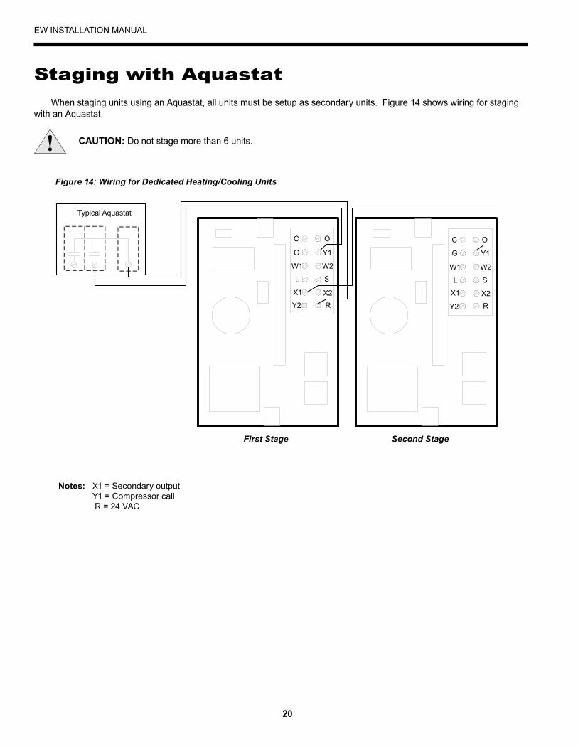
When staging units using an Aquastat, all units must be setup as secondary units. Figure 14 shows wiring for staging with an Aquastat.
Secondary Unit(SL=1)
Second Stage Control BoxFirst Stage Control Box
Secondary Unit(SL=1)
C
G
W1
L
X1
Y2
O
Y1
W2
S
X2
R
C
G
W1
L
X1
Y2
O
Y1
W2
S
X2
R
Typical Aquastat
Figure 14: Wiring for Dedicated Heating/Cooling Units
First Stage Second Stage
Notes: X1 = Secondary output Y1 = Compressor call R = 24 VAC
CAUTION:Do not stage more than 6 units.
Staging with Aquastat

21
EW INSTALLATION MANUAL
Converting to a Dedicated Cooling Unit
Procedure to Convert a Heating Only Unit to a Cooling Only Unit All non-reversible EW units are built at the factory as dedicated heating units. Follow the procedures below to make the unit a dedicated cooling unit.1. Shut off all power to the unit.2. Remove the top and access panel.3. Remove the brass in-well thermistor from the load water-in line.4. Remove the brass plug from the source water-in line.5. Place new Teflon® tape on the threads of the brass in-well thermistor.6. Thread the brass in-well thermistor into the source water-in line.7. Make sure the thermistor wires do not touch the discharge line.8. Place new Teflon® tape on the threads of the brass plug.9. Thread the brass plug into the load water-in line.10. Refer to the labels on the unit for the location of ports and lines.11. Connect the “Source Water-In” line to the port marked “Load Water-In”. Then, connect the “Source Water-Out” line to
the port marked “Load Water-Out”.12. Connect the “Load Water-In” line to the port marked “Source Water-In”. Then, connect the “Load Water-Out” line to the
port marked “Source Water-Out”.13. Open the control box.14. Find the connection marked “P4” as shown in
Figure 1515. Move the “P4” jumper from across 1 and 2 to
across 2 and 3.16. Close the control box and secure the screws.17. Replace the top and access panel.18. Make sure all screws have been re-installed.19. Turn on the power.20. Using the touch-pad, press the up arrow.21. The displays should blink “44” to show set point.
Now, the unit should operate as a cooling only unit.
Jumper Pin Location The location of the jumper pin determines the controller’s mode of operation. Move the jumper pins to the correct location for dedicated heating, dedicated cooling or reversible settings as indicated below. Dedicated heating - 1 & 2 * Dedicated cooling - 2 & 3 Reversible - 3 & 4 *
* Indicates factory setting.
NOTE: A REVERSIBLE UNIT CAN NOT BE CONFIGURED TO HEATING ONLY.
Figure 15: Control Board with Jumper
P4
P5 Key Pad(Interface)
P4Not Used
P2
P1

22
EW INSTALLATION MANUAL
Unit Startup
Before Powering Unit Check the following:
High voltage wiring is correct and matches the nameplate.•Fuses, breakers and wire size are correct.•Piping is completed and water system has been cleaned and flushed.•Air is purged from the closed loop system.•Isolation valves are open and loop water control valves or loop pumps are wired.•Service/access panels are in place.•
Primary Unit StartupApply power to the unit. Upon power up, the unit will display the current operation mode. 1.• H for dedicated heating. • C for dedicated cooling. • U for reversible units.Press the mode button. The LED screen will display the current entering water temperature. The load pump will acti-2.vate after a 5 minute delay.Once the load pump has been active for 3 minutes, the controller will sample the temperature of the water system. In 3.heating mode, when the temperature of the water shown on the display is lower than the set point the compressor will activate.By using a pressure gauge and the P/T ports, check the pressure drop through both the load and source coaxes. 4.Compare this to the capacity tables in the specification catalog to verify the proper flow rate through the unit.Verify that the compressor, load side and source side pumps are operating.5.After determining the flow rates, use a thermometer and the PT ports to determine the change in temperature on both 6.the load and source side coaxes.Compute the formula 7. GPMflowrateXChangeintemperatureX500(485onsourcesideifantifreezeisusedintheloop)=HeatofExtractiononthesourcesideinheating,HeatofRejectiononthesourcesideincooling. To ensure proper operation, compare these values to the capacity tables in the specification catalog.Press the down arrow on the keypad to reduce the set point below the incoming load temperature. Compressor should 8.shut off and the load pump should shut off 30 seconds after the compressor.Wait 7 minutes. The load pump should start to sample load temperature.9.Compressor and source side circulator should not start.10.Press the up arrow on the keypad to increase the set point to 5 degrees above the water temperature displayed on the 11.LED screen.Three minutes after the load pump activates, the compressor and source pump should activate.12.
Secondary Unit StartupApply power to the unit.1.After a three to five-minute delay, the water temperature shall be sampled. If the controller receives a remote aquastat 2.signal, the compressor shall activate.Verify that the compressor and load side, source side pumps are running.3.By using a pressure gauge and the PT ports, check the pressure drop through both the load and source coaxes, and 4.compare this to the capacity tables in the specification catalog to verify the proper flow rate through the unit.After determining the flow rates, use a thermometer and the PT ports to determine the change in temperature on both 5.the load and source side coaxes.Compute the formula 6. GPMflowrateXChangeintemperatureX500(485onsourcesideifantifreezeisusedintheloop)=HeatofExtractiononthesourcesideinheating,Heatofrejectiononthesourcesideincooling. To ensure proper operation, compare these values to the capacity tables in the specification catalog.Press the down arrow on the control to disrupt the remote aquastat signal. Unit should shut off.7.Instruct the owner or operator about the correct control and system operation.8.

23
EW INSTALLATION MANUAL
The control panel allows you to access the service menu on the unit. The control panel has three 7-segment LED screens that display the:
Water temperature• Configuration menu•
There are 6 LED indicators that indicate when SECONDARY OUTPUT is active or the unit is on one of the following modes:
Standby Mode• Heating Mode• Cooling Mode• Primary (Master) Mode•
The control panel has both UP and DOWN (arrow) buttons and a MODE button. The UP and DOWN buttons allow you to change the set point or scroll through the configuration menu. The MODE button allow you to change mode as well as enter and exit parameters while in configuration mode.
The Configuration MenuThe configuration menu allows you to properly set and adjust all of the unit’s operating parameters to fit your application.To enter configuration mode and configure parameters, follow these procedures:
Hold down both the UP and DOWN buttons simultaneously for five seconds, or until the LED screen displays “LC”.1. Press the UP or DOWN arrow until “50” is displayed.2. Press the MODE button. The screen should display “SC” to indicate the controller is in configuration mode.3. Once in configuration mode, press the UP or DOWN arrow to scroll through the menu.4. Press the MODE button to enter the parameter. (Refer to the parameter table on page 23 for a list of configurable 5. parameters.)Once in the parameter, press the UP or DOWN arrow to change the parameter.6. Press the MODE button to return to the main menu.7.
Note: The controller will exit the configuration mode after 30 seconds if no key is pressed.
Changing the Set PointPressing the UP or DOWN arrow once will display the set point.1. The set point will flash.2. When the set point is flashing, the UP and DOWN arrow will change the set point by one degree.3.
Lockout ModeDuring lockout mode, the display will flash the lockout code corresponding to the fault condition that caused the initial
lockout. The compressor, loop pumps, and secondary output are de-energized.
Notes: Lockout modes of any kind can be reset by pressing the mode button twice. Recycling the power also resets the lockout.
High Pressure This lockout mode occurs when the normally closed safety switch is momentarily opened.Low Pressure This lockout occurs when the normally closed switch is opened for 30 continuous seconds.Freeze Sensing This lockout mode occurs when the freeze thermistor temperature (located between the TXV and coax) is at or below the selected freeze sensing point (Open Loop, Closed Loop, or Process) for 30 continuous seconds.
Control Panel

24
EW INSTALLATION MANUAL
Remote Aquastat Secondary Mode (Y1)
The compressor shall engage 10 seconds after the Y1 call has been received. The compressor shall de-activate 10 seconds after the Y1 has been removed. The secondary output is controlled by a Derivative Controller. If the change in the water temperature is less than a selected value (d) in a selected period of time (P), the secondary output shall activate.
Parameter Functions and Settings
Control Panel (cont.)
PARAMETER FUNCTION DESCRIPTION FACTORYSETTING RANGE INCREMENTS
SCCalibrate the WaterSensor
This will allow the temperature displayed to be adjusted to match a temperature reading from an external source.
0° -9° to 10° 1
dBDead Band This parameter is used to determine when the com-
pressor should be activated. If the set point is below the set point minus the dB value (in heating mode) then the compressor will activate.
1°F 1° to 15° 1
CFCelsius/Fahrenheit Selection
This parameter selects the units for which the temperature will be displayed. F F or C N/A
FP
Freeze Sensing Setting
There are three settings for this parameter; OL, CL, and P. OL is the open loop setting which corre-sponds to 32°F (0°C). CL is the closed loop setting which is 15°F (-10°C). P is the process setting which is 5°F (-15°C).
32°F P,CL,OL N/A
SLPrimary/Secondary Setting
Primary mode utilizes an internal aquastat to deter-mine the activity of the compressor. In secondary mode the compressor output is determined by an external aquastat
0(Primary) 0 or 1 0 = Primary
IC
Initial Condition
This parameter is used to determine the state of the secondary output of the primary unit. If the actual water temperature is greater than the IC value away from the set point, the secondary output will be activated.
10° 0° to 20° 1°
dDerivative This parameter is used to determine the state of the
secondary output of the primary and secondary unit. If the change in temperature is less than the d value the secondary output will activate.
1°F 0° to 5° 1°
P Period This determines how often the derivative will be calculated. 5 min 1 to 5 min 1 min
PS
Pump Sampling Time Selection
This parameter determines how long the pump is activated before the controller takes a sample of the water temperature. The range of this parameter is from 1 to 5 minutes and is factory set to 3 minutes. The pump can also be set to run continuously when PS is set to C.
3 min 1 to 5 min or C 1 min
FdFreeze Sensing Display
This displays the current temperature of the freeze sensing sensor. N/A 0° to 130° N/A

25
EW INSTALLATION MANUAL
Capacity Data
A B
C D
MODEL
SOURCE LOADCAPACITY
COPFLOW SWPD FLOW LWPD
EWT GPM L/s PSI FTHD BAR EWT GPM L/s PSI FT
HD BAR HEATOUTPUT kW
EW02032 6 0.38 3.8 8.9 0.26 104 3 0.19 0.9 2.1 0.06 22.2 6.5 2.832 9 0.57 9.0 20.8 0.62 104 9 0.57 8.2 18.9 0.57 22.5 6.6 3.0
EW03032 8 0.50 2.7 6.2 0.19 104 5 0.32 1.6 3.6 0.11 29.0 8.5 3.032 12 0.76 5.2 12.1 0.36 104 12 0.76 4.8 11.2 0.33 29.5 8.6 3.1
EW04232 11 0.69 2.8 6.4 0.19 104 7 0.44 1.7 3.9 0.12 44.9 13.2 2.932 16.5 1.04 5.5 12.8 0.38 104 16.5 1.04 5.0 11.6 0.35 45.5 13.3 3.0
EW060*32 14 0.88 3.0 7.0 0.21 104 11 0.69 2.2 5.1 0.15 59.2 17.4 2.832 21 1.32 5.9 13.7 0.41 104 21 1.32 5.0 11.6 0.34 60.7 17.8 3.0
MODEL
SOURCE LOADCAPACITY
EERFLOW SWPD FLOW LWPD
EWT GPM L/s PSI FTHD BAR EWT GPM L/s PSI FT
HD BAR MBTU kW
EW030R77 8 0.50 2.4 5.5 0.16 53.6 8.0 0.50 2.6 6.0 0.18 21.9 6.42 10.6777 12 0.76 5.0 11.6 0.34 53.6 12.0 0.76 5.4 12.6 0.37 22.1 6.48 10.93
EW042R77 11 0.69 2.4 5.6 0.17 53.6 11.0 0.69 2.6 6.0 0.18 42.7 12.51 12.4277 16.5 1.04 5.3 12.2 0.36 53.6 16.5 1.04 5.7 13.1 0.39 43.2 12.66 12.86
EW060R*77 14 0.88 2.4 5.5 0.17 53.6 14.0 0.88 2.7 6.3 0.19 58.0 17.00 12.5477 21 1.32 5.6 12.9 0.39 53.6 21.0 1.32 6.0 13.9 0.41 61.1 17.91 13.47
Heating Capacity Data
Cooling Capacity Data
NOTES: Based on 60 Hz., single phase. For more detailed data, refer to pages 14-20.* For 3 phase EW060 capacity, multiply above data by .948. For 3 phase EW060 power, multiply above data by .943.
NOTES: Based on 60 Hz., single phase. For more detailed data, refer to pages 14-20.* For 3 phase EW060R capacity, multiply above data by .948. For 3 phase EW060R power, multiply above data by .943.

26
EW INSTALLATION MANUAL
SOURCEEWT
MAXHEATINGSETPOINT100°F 105°F 110°F 115°F 120°F 125°F 130°F
GPM WPD GPM WPD GPM WPD GPM WPD GPM WPD GPM WPD GPM WPD30°F 1.5 0.3 1.5 0.3 1.5 0.3 1.5 0.3 1.5 0.3 1.5 0.3 2.0 0.640°F 1.5 0.3 1.5 0.3 1.5 0.3 1.5 0.3 1.5 0.3 2.0 0.6 2.5 0.850°F 1.5 0.3 1.5 0.3 1.5 0.3 1.5 0.3 2.0 0.6 2.5 0.8 3.0 1.260°F 1.5 0.3 1.5 0.3 1.5 0.3 2.0 0.6 2.5 0.8 3.0 1.2 3.5 1.670°F 1.5 0.3 1.5 0.3 2.0 0.6 2.5 0.8 3.0 1.2 3.5 1.6 4.0 2.080°F 1.5 0.3 2.0 0.6 2.5 0.8 3.0 1.2 3.5 1.6 4.0 2.0 6.0 4.390°F 2.0 0.6 2.5 0.8 3.0 1.2 3.5 1.6 4.0 2.0 6.0 4.3 7.0 5.7100°F 2.5 0.8 3.0 1.2 3.5 1.6 4.0 2.0 6.0 4.3 7.0 5.7 7.5 6.4110°F 3.0 1.2 3.5 1.6 4.0 2.0 6.0 4.3 7.0 5.7 7.5 6.4 9.0 9.0
SOURCEEWT
MAXHEATINGSETPOINT100°F 105°F 110°F 115°F 120°F 125°F 130°F
GPM WPD GPM WPD GPM WPD GPM WPD GPM WPD GPM WPD GPM WPD30°F 2.5 0.3 2.5 0.3 2.5 0.3 2.5 0.3 2.5 0.3 2.5 0.3 3.0 0.540°F 2.5 0.3 2.5 0.3 2.5 0.3 2.5 0.3 2.5 0.3 3.0 0.5 3.5 0.850°F 2.5 0.3 2.5 0.3 2.5 0.3 2.5 0.3 3.0 0.5 3.5 0.8 4.5 1.060°F 2.5 0.3 2.5 0.3 2.5 0.3 3.0 0.5 3.5 0.8 4.5 1.0 5.5 1.470°F 2.5 0.3 2.5 0.3 3.0 0.5 3.5 0.8 4.5 1.0 5.5 1.4 6.5 2.080°F 2.5 0.3 3.0 0.5 3.5 0.8 4.5 1.0 5.5 1.4 6.5 2.0 9.0 3.690°F 3.0 0.5 3.5 0.8 4.5 1.0 5.5 1.4 6.5 2.0 9.0 3.6 11.0 5.2100°F 3.5 0.8 4.5 1.0 5.5 1.4 6.5 2.0 9.0 3.6 11.0 5.2 11.5 5.6110°F 4.5 1.0 5.5 1.4 6.5 2.0 9.0 3.6 11.0 5.2 11.5 5.6
SOURCEEWT
MAXHEATINGSETPOINT100°F 105°F 110°F 115°F 120°F 125°F 130°F
GPM WPD GPM WPD GPM WPD GPM WPD GPM WPD GPM WPD GPM WPD30°F 3.5 0.3 3.5 0.3 3.5 0.3 3.5 0.3 3.5 0.3 3.5 0.3 4.5 0.540°F 3.5 0.3 3.5 0.3 3.5 0.3 3.5 0.3 3.5 0.3 4.5 0.5 5.5 0.750°F 3.5 0.3 3.5 0.3 3.5 0.3 3.5 0.3 4.5 0.5 5.5 0.7 6.5 1.060°F 3.5 0.3 3.5 0.3 3.5 0.3 4.5 0.5 5.5 0.7 6.5 1.0 7.5 1.370°F 3.5 0.3 3.5 0.3 4.5 0.5 5.5 0.7 6.5 1.0 7.5 1.3 8.5 1.780°F 3.5 0.3 4.5 0.5 5.5 0.7 6.5 1.0 7.5 1.3 8.5 1.7 12.5 3.490°F 4.5 0.5 5.5 0.7 6.5 1.0 7.5 1.3 8.5 1.7 12.5 3.4 14.5 4.4100°F 5.5 0.7 6.5 1.0 7.5 1.3 8.5 1.7 12.5 3.4 14.5 4.4 16.5 5.6110°F 6.5 1.0 7.5 1.3 8.5 1.7 12.5 3.4 14.5 4.4 16.5 5.6
EW020 Minimum Load Flow
EW030 Minimum Load Flow
EW042 Minimum Load Flow
Flow Rates and Pressure DropThe following tables list the required minimum flow rates (GPM) for all combinations of source temperatures from 30°F to
110°F [-1°C to 43°C] and load temperatures from 100°F to 130°F [38°C to 54°C]. For example, on an EW020, heating water to a temperature of 125°F [52°C] with a 70°F [21°C] source temperature requires a minimum flow of 3.5 GPM. Refer to the tables on page 12 for required source side flow rates.
WARNING:Operating the unit outside of the minimum flow rate parameters will trip the high pressure switch and/or result in compressor damage.
NOTE:All pressure drops are in PSI.

27
EW INSTALLATION MANUAL
SOURCEEWT
MAXHEATINGSETPOINT100°F 105°F 110°F 115°F 120°F 125°F 130°F
GPM WPD GPM WPD GPM WPD GPM WPD GPM WPD GPM WPD GPM WPD30°F 5.5 0.5 5.5 0.5 5.5 0.5 5.5 0.5 5.5 0.5 5.5 0.5 6.0 0.640°F 5.5 0.5 5.5 0.5 5.5 0.5 5.5 0.5 5.5 0.5 6.0 0.6 7.5 0.950°F 5.5 0.5 5.5 0.5 5.5 0.5 5.5 0.5 6.0 0.6 7.5 0.9 9.0 1.360°F 5.5 0.5 5.5 0.5 5.5 0.5 6.0 0.6 7.5 0.9 9.0 1.3 10.5 1.770°F 5.5 0.5 5.5 0.5 6.0 0.6 7.5 0.9 9.0 1.3 10.5 1.7 12.0 2.180°F 5.5 0.5 6.0 0.6 7.5 0.9 9.0 1.3 10.5 1.7 12.0 2.1 18.0 4.390°F 6.0 0.6 7.5 0.9 9.0 1.3 10.5 1.7 12.0 2.1 18.0 4.3 21.0 5.7100°F 7.5 0.9 9.0 1.3 10.5 1.7 12.0 2.1 18.0 4.3 21.0 5.7
110°F 9.0 1.3 10.5 1.7 12.0 2.1 18.0 4.3 21.0 5.7
EW060 Minimum Load Flow
MODEL MINIMUMOPENLOOPFLOWRATE
MINIMUMCLOSEDLOOPFLOWRATE
MAXIMUMFLOWRATE
EW020 3.0 6.0 9.0EW030 4.0 8.0 12.0EW042 5.5 11.0 16.5EW060 7.0 14.0 21.0
Source Flow Rates
Pressure Drop (PSI @ 90°FEWT)
EW020
EW030
EW042
EW060
0.0
1.0
2.0
3.0
4.0
5.0
6.0
7.0
8.0
9.0
10.0
11.0
12.0
13.0
14.0
15.0
16.0
17.0
18.0
19.0
20.0
21.0
22.0
23.0
0.0 1.0 2.0 3.0 4.0 5.0 6.0 7.0 8.0 9.0 10.0
Pressure Drop (PSI)
Flow
Rat
e (G
PM)
Flow Rates and Pressure Drop (cont.)

28
EW INSTALLATION MANUAL
Should a major problem develop, refer to the following information for possible causes and corrective steps:
Compressor Won’t Run:1. The fuse may be blown or the circuit breaker is open. Check electrical circuits and motor windings for shorts or
grounds. Investigate for possible overloading. Replace fuse or reset circuit breakers after the fault is corrected.2. Supply voltage may be too low. Check voltage with a volt meter.3. Remote control system may be faulty. Check aquastat for correct wiring, setting and calibration. Check 24-volt trans-
former for burnout.4. Wires may be loose or broken. Replace or tighten.5. The low pressure switch may have tripped due to one or more of the following:
a. Fouled or plugged coaxial heat exchangers b. Low or no water flow (source side heating, load side cooling) c. Water too cold (source side heating) d. Low refrigerant
6. The high pressure switch may have tripped due to one or more of the following: a. Fouled or plugged coaxial heat exchanger b. Low or no water flow (source side cooling, load side heating) c. Water too warm (source side cooling)
7. Check the capacitor.8. The compressor overload protection may be open. If the compressor dome is extremely hot, the overload will not reset
until cooled down. If the overload does not reset when cool, it may be defective. If so, replace the compressor.9. The internal winding of the compressor motor may be grounded to the compressor shell. If so, replace the compressor.10. The compressor winding may be open. Check continuity with an ohm meter. If the winding is open, replace the com-
pressor.
Insufficient Cooling or Heating1. Check aquastat for improper location (secondary mode only).2. Check for restriction in water flow.3. Check subcooling for low refrigerant charge.4. The reversing valve may be defective and creating a bypass of refrigerant. If the unit will not cool, check the reversing
valve coil.5. Check thermal expansion valve for possible restriction of refrigerant flow.
Noisy Unit Operation1. Check compressor for loosened mounting bolts. Make sure compressor is floating free on its isolator mounts.2. Check for tubing contact with the compressor or other surfaces. Readjust it by bending slightly.3. Check screws on all panels.4. Check for chattering or humming in the contactor or relays due to low voltage or a defective holding coil. Replace the
component.5. Check for proper installation of vibration absorbing material under the unit. Unit must be fully supported, not just on
corners.6. Check for abnormally high discharge pressures.
Troubleshooting

29
EW INSTALLATION MANUAL
Troubleshooting Controls
Check the unit. If a lockout mode is displayed, refer to the table below to determine the meaning of the failure. Follow the procedure listed to correct the problem.
Check the mode:1. If the unit is running on the internal aquastat, verify the unit is in “Primary” mode. The SL should be set to 0 in the
setup menu.2. If the unit is running on an external aquastat, the SL should be set to 1.
Check the jumpers on the control board:1. Refer to Figure 15 on page 20 to see the location of the jumper on the board. If the unit is a heating only unit, the
jumper should be across 1 and 2.2. If the unit is a cooling only unit, the jumper should be across 2 and 3.3. If the unit is a reversible unit, the jumper should be across 3 and 4.
Check the thermistor calibration:1. Using a thermometer in the P/T port, check the incoming water temperature.2. Verify that the measured temperture is within 3 degrees of the temperature displayed on the unit.3. If it is not, adjust the calibration in the setup menu.
DISPLAY FAILURE DIAGNOSTICDC Freeze sensing thermistor is closed (shorted) Replace the freeze sensing thermistor (clip-on therm-
istor)DO Freeze sensing thermistor is open Verify that the freeze sensing thermistor is secured
properly in the board connector. If the connection is securre, replace the thermistor.
FP Freeze sensing The water going through the unit has reached the freeze point setting (P=5, CL=15, OL=30). Verify that the freeze sensing setting is correct for the applica-tion.
HC Water set point thermistor is closed (shorted) Replace the water set point thermistor (threaded thermistor).
HP High Pressure The unit has cut out on high pressure. Discharge pressure is >600.
LP Low Pressure The unit has cut out on low pressure. Suction pres-sure is <40
PO Water set point thermistor is open Verify that the water set point thermistor is properly secured in the board connector. If the connection is secure, replace the thermistor.
Troubleshooting (cont.)

30
EW INSTALLATION MANUAL
Preventive Maintenance1. Keep all air out of the water lines. An open loop system should be checked to ensure that the well head is not allowing
air to infiltrate the water line. Lines should always be airtight.2. Keep the system under pressure at all times. In open loop systems, it is recommended that a water control valve be
placed in the discharge line to prevent loss of pressure during off cycles. Closed loop systems must have a positive static pressure.
Notes: If the installation is performed in an area with a known high mineral content in the water, it is best to establish a periodic maintenance schedule to check the water-to-refrigerant heat exchanger on a regular basis. Should periodic clean-ing be necessary, use standard cleaning procedures which are compatible with either the cupronickel or copper water lines. Generally, the more water flowing through the unit, the less chance there is for scaling. Low GPM flow rates produce higher temperatures through the coil. To avoid excessive pressure drop and the possibility of copper erosion, do not exceed GPM flow rate as shown on the specification sheets for each unit.
Cleaning Procedure1. Close the inlet and outlet water valves to isolate the heat pump from the well system, water heater or loop pumps.2. Disconnect piping and remove solenoid valve, pumps, etc, from the inlet and outlet connections on the heat pump.3. Connect plastic hoses from the circulating pump* to the outlet of the water-to-refrigerant heat exchanger to be de-limed
(refer to Figure 16).4. Connect a plastic hose from the circulating pump inlet to the bottom of a plastic five(5) gallon pail (refer to Figure 16).5. Connect a plastic hose from the inlet line of the water-to-refrigerant heat exchanger to the plastic pail. Secure tightly to
ensure that circulating solution does not spill (refer to Figure 16).6. Partially fill the plastic pail with clear water (about two-thirds full) and prime the circulating pump. Circulate until lines
are full.7. Start the circulating pump and slowly add a commercial scale remover** to the water as recommended by the scale
remover manufacturer’s directions.8. Be sure the pump circulation is opposite to the normal water flow through the water-to-refrigerant heat exchanger.9. Maintain re-circulation until all scale and other material has been dissolved and flushed from the heat exchanger.10. Upon completion of the procedure. Safely dispose of the solution.11. Rinse the pump and plastic pail. Refill with clear water.12. Start the pump circulation and flush the system until all acid residue has been removed from the system. Refill the
plastic pail until only clear water is circulated.13. Turn off the circulating pump and disconnect all hoses and fittings.14. Replace solenoid valves, pumps, hoses and other devices in their original locations. On closed loop systems, be sure
to purge between the flow center and unit to avoid getting air into the loop.15. Put the heat pump back into operation. Check for proper operating temperature.
WARNING: This process involves acausticsolutionandmaybeharmfultopeopleandanimals.Wearprotectiveequipment (glasses, rubber gloves,apron,etc.)
Notes: *Virginia Chemical Co. makes a Pump model H460.* W.W. Granger Co. sells a Pump #2P-017 made by Little Giant.**Virginia Chemical Co. makes a liquid ice machine cleaner which should be used on water-to-refrigerant heat exchangers serving a domestic hot water system. Calci-Solve by NYCO is available for use on other heat exchangers
Five-gallon Bucket
Pump
Figure 16: Cleaning Connections


Manufactured byWaterFurnace International, Inc.9000 Conservation WayFort Wayne, IN 46809
Product: EW SeriesType: Hydronic Heat PumpsSize: 2 thru 5 Ton
Document Type: Installation ManualPart Number: IM1469
IM1469 1 1/08
WaterFurnace International, Inc., 9000 Conservation Way, Fort Wayne, IN 46809-9794. WaterFurnace has a policy of continual product research and development and reserves the right to change
design and specifications without notice. © 2008 WaterFurnace International Inc.