evs25 shenzhen, china, nov 5-9, 2010 wireless power ... wireless power transfer system via magnetic...
TRANSCRIPT

EVS25 World Battery, Hybrid and Fuel Cell Electric Vehicle Symposium 1
EVS25 Shenzhen, China, Nov 5-9, 2010
Wireless Power Transfer System via Magnetic Resonant Coupling at Fixed Resonance Frequency
-Power Transfer System Based on Impedance Matching - TeckChuan Beh1, Masaki Kato1, Takehiro Imura1, Yoichi Hori1
1Department of Advanced Energy, Graduate School of Frontier Science, University of Tokyo, Frontier Sciences, Transdisciplinary Sciences Building, 5-1-5, Kashiwanoha, Kashiwa Chiba, Japan
E-mail: [email protected], [email protected], [email protected], [email protected]
Abstract
To increase the usage of electric vehicles (EV), a safe and convenient method to charge the vehicles is essential.
Recently, an efficient mid range wireless power transfer that uses magnetic resonant coupling, WiTricity, was
proposed, and has received much attention due to its practical range and efficiency. Studies show that the resonance
frequency of the antennas changes as the gap between the antennas change. However, when this technology is
applied in the MHz range (which allows small sized antennas), the usable frequency is bounded by the Industrial,
Science, Medical (ISM) band. Therefore, to achieve maximum power transmission efficiency, the resonance
frequency has to be fixed within the ISM band. In this paper, the possibility of using impedance matching (IM)
networks to adjust the resonance frequency of a pair of antennas at a certain distance to 13.56MHz is studied. The
simulations and experiments show that the IM circuits can change the frequency to 13.56MHz for different air gaps,
improving the power transfer efficiency. Experiments also show that IM can be achieved just by observing and
minimizing the reflected wave.
Keywords— wireless power transfer, EV charging, magnetic resonance, magnetic coupling, impedance matching
1. Introduction Wireless power transfer is essential for the
spread of EVs as it provides a safe and convenient way to charge the vehicles. When wireless power transfer is achieved, the process the process of charging the devices will be made a lot more convenient as we do not have to plug the cord into the socket. Furthermore, as power can be constantly transferred to the vehicles, the battery size can be reduced. Also, the danger of being electrocuted due to the wear and tear of an old cord, or rain will be avoided as the process of handling the power cord is unnecessary, thus making the charging process safer. To achieve wireless charging, the wireless power transfer system must satisfy these three conditions: high efficiency, large air gaps, and high power.
Presently, the most popular wireless transfer technologies are the electromagnetic induction and the microwave power transfer. However, the electromagnetic induction method has a short range [3], and the microwave power transfer has a low efficiency as it involves radiation of electromagnetic waves. Recently, a highly efficient mid-range wireless power transfer technology using magnetic resonant coupling, WiTricity, was proposed. It is a system that transfers power in between two resonating antennas through magnetic coupling. It satisfies all three conditions to make wireless charging possible as it has a high efficiency at mid range. (Approximately 90% at 1m and 50% at 2m [1] at 60W ).
Until now, this phenomenon was explained using mode coupling theory. However, this theory is this theory is often complicated, and inconvenient
World Electric Vehicle Journal Vol. 4 - ISSN 2032-6653 - © 2010 WEVA Page000744
EVS25 World Battery, Hybrid and Fuel Cell Electric Vehicle Symposium 2
when it comes to designing the circuits around the system. In this paper, we study this phenomenon using antenna design theories and circuit design theories. The characteristics of the antennas are explained using equivalent circuits, electromagnetic analysis, and experiments. The frequency characteristics of the antennas and its relation to the efficiency are studied.
This paper studies the wireless power transfer system via magnetic resonance coupling at a fixed resonance frequency (13.56MHz). A system to improve the efficiency of the power transfer based on impedance matching (IM) is proposed. The aim is to improve the efficiency by using an IM circuit to tune the resonance frequency of the system to the frequency of the power source. The parameters of the tuning circuit are calculated based on the equivalent circuit of the antennas, and impedance matching theories. Its effects are studied with experiments and simulations.
2. Theory of Magnetic Resonant Coupling (MRC)
In this paper, we study this phenomenon using antenna design theories and circuit design theories. Using the equivalent circuit, the frequency characteristics of the antennas can be estimated up to an accuracy of 5% error.
2.1 Equivalent Circuit of MRC Magnetic resonant coupling involves creating
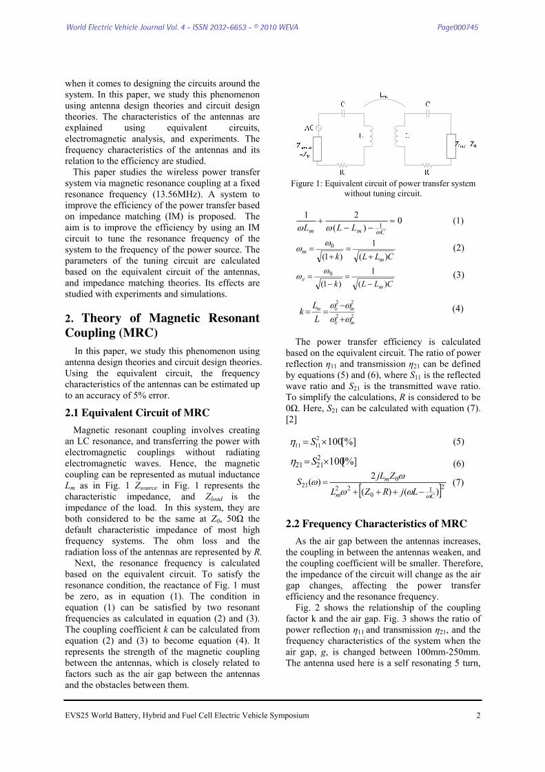
an LC resonance, and transferring the power with electromagnetic couplings without radiating electromagnetic waves. Hence, the magnetic coupling can be represented as mutual inductance Lm as in Fig. 1 Zsource in Fig. 1 represents the characteristic impedance, and Zload is the impedance of the load. In this system, they are both considered to be the same at Z0, 50Ω the default characteristic impedance of most high frequency systems. The ohm loss and the radiation loss of the antennas are represented by R.
Next, the resonance frequency is calculated based on the equivalent circuit. To satisfy the resonance condition, the reactance of Fig. 1 must be zero, as in equation (1). The condition in equation (1) can be satisfied by two resonant frequencies as calculated in equation (2) and (3). The coupling coefficient k can be calculated from equation (2) and (3) to become equation (4). It represents the strength of the magnetic coupling between the antennas, which is closely related to factors such as the air gap between the antennas and the obstacles between them.
Figure 1: Equivalent circuit of power transfer system
without tuning circuit.
0)(
211 =
−−+
Cmm LLL ωωω (1)
CLLk mm
)(1
)1(0
+=
+=
ωω (2)
CLLk me
)(1
)1(0
−=
−=
ωω (3)
(4)
The power transfer efficiency is calculated based on the equivalent circuit. The ratio of power reflection η11 and transmission η21 can be defined by equations (5) and (6), where S11 is the reflected wave ratio and S21 is the transmitted wave ratio. To simplify the calculations, R is considered to be 0Ω. Here, S21 can be calculated with equation (7). [2]
(5) (6)
[ ]210
220
21)()(
2)(
Cm
m
LjRZL
ZjLS
ωωω
ωω
−+++=
(7)
2.2 Frequency Characteristics of MRC As the air gap between the antennas increases,
the coupling in between the antennas weaken, and the coupling coefficient will be smaller. Therefore, the impedance of the circuit will change as the air gap changes, affecting the power transfer efficiency and the resonance frequency.
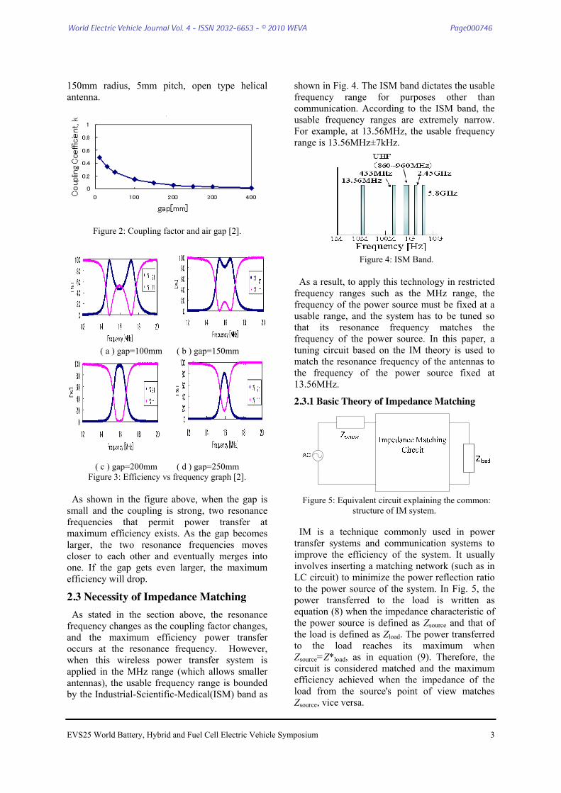
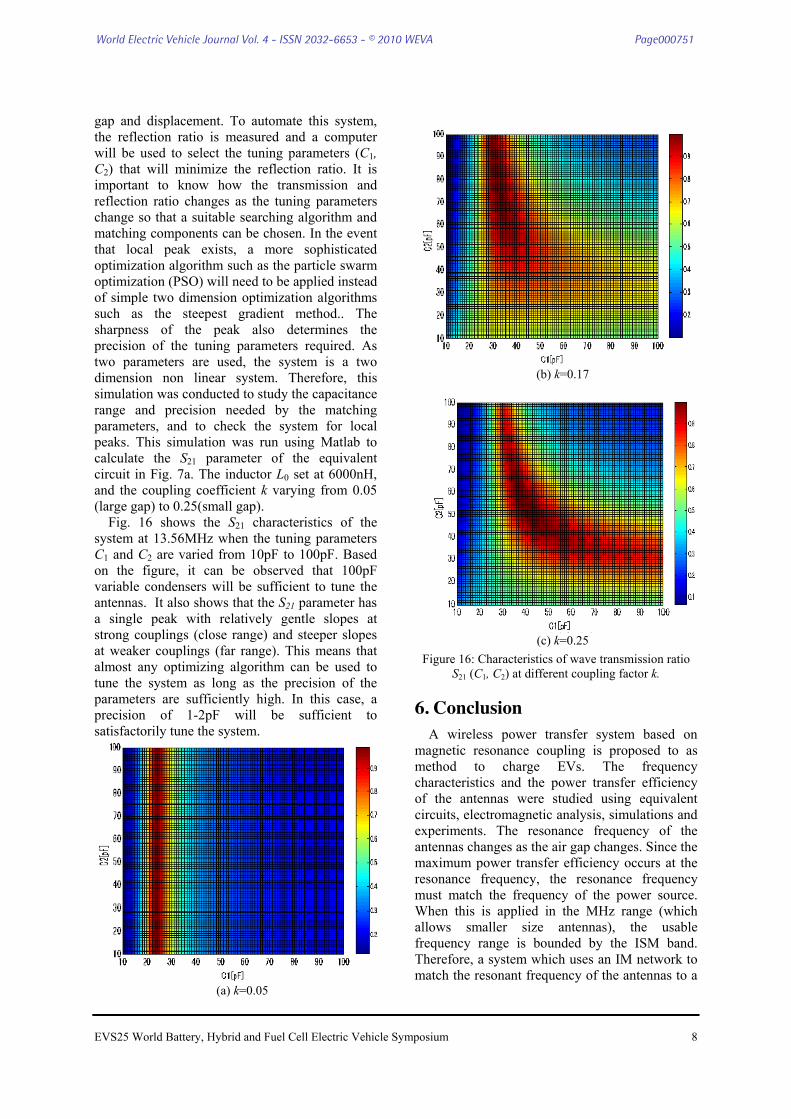
Fig. 2 shows the relationship of the coupling factor k and the air gap. Fig. 3 shows the ratio of power reflection η11 and transmission η21, and the frequency characteristics of the system when the air gap, g, is changed between 100mm-250mm. The antenna used here is a self resonating 5 turn,
[%]10022121 ×=Sη
[%]10021111 ×= Sη
22
22
me
mem
LL
kωωωω+−
==
World Electric Vehicle Journal Vol. 4 - ISSN 2032-6653 - © 2010 WEVA Page000745
EVS25 World Battery, Hybrid and Fuel Cell Electric Vehicle Symposium 3
150mm radius, 5mm pitch, open type helical antenna.
Figure 2: Coupling factor and air gap [2].
( a ) gap=100mm ( b ) gap=150mm
( c ) gap=200mm ( d ) gap=250mm
Figure 3: Efficiency vs frequency graph [2]. As shown in the figure above, when the gap is
small and the coupling is strong, two resonance frequencies that permit power transfer at maximum efficiency exists. As the gap becomes larger, the two resonance frequencies moves closer to each other and eventually merges into one. If the gap gets even larger, the maximum efficiency will drop.
2.3 Necessity of Impedance Matching As stated in the section above, the resonance
frequency changes as the coupling factor changes, and the maximum efficiency power transfer occurs at the resonance frequency. However, when this wireless power transfer system is applied in the MHz range (which allows smaller antennas), the usable frequency range is bounded by the Industrial-Scientific-Medical(ISM) band as
shown in Fig. 4. The ISM band dictates the usable frequency range for purposes other than communication. According to the ISM band, the usable frequency ranges are extremely narrow. For example, at 13.56MHz, the usable frequency range is 13.56MHz±7kHz.
Figure 4: ISM Band.
As a result, to apply this technology in restricted
frequency ranges such as the MHz range, the frequency of the power source must be fixed at a usable range, and the system has to be tuned so that its resonance frequency matches the frequency of the power source. In this paper, a tuning circuit based on the IM theory is used to match the resonance frequency of the antennas to the frequency of the power source fixed at 13.56MHz.
2.3.1 Basic Theory of Impedance Matching
Figure 5: Equivalent circuit explaining the common:
structure of IM system. IM is a technique commonly used in power
transfer systems and communication systems to improve the efficiency of the system. It usually involves inserting a matching network (such as in LC circuit) to minimize the power reflection ratio to the power source of the system. In Fig. 5, the power transferred to the load is written as equation (8) when the impedance characteristic of the power source is defined as Zsource and that of the load is defined as Zload. The power transferred to the load reaches its maximum when Zsource=Z*load, as in equation (9). Therefore, the circuit is considered matched and the maximum efficiency achieved when the impedance of the load from the source's point of view matches Zsource, vice versa.
World Electric Vehicle Journal Vol. 4 - ISSN 2032-6653 - © 2010 WEVA Page000746

EVS25 World Battery, Hybrid and Fuel Cell Electric Vehicle Symposium 4
(8)
(9)
(10)
(11)
The IM circuit can be considered as a two-port
network that can be described with equation (10). The matching conditions are satisfied when the parameters satisfy equation (11).
3. Proposed Wireless Power Transfer System
Fig. 6 shows the diagram of the proposed system to improve the efficiency of wireless power transfer via magnetic resonant coupling with a matching circuit.
As shown in Fig. 6, the wireless power transfer system involves resonating two antennas with identical self resonance frequency (13.56MHz) using a high frequency power source. The power is transmitted through magnetic resonant coupling in between the two antennas at the resonance frequencies. The power transferred is rectified and used to charge energy storage mediums such as batteries and electric double layer capacitors (EDLC).
As stated above, this research focuses on the transmitting part of the system, and the load of the system is set at 50Ω. Under normal circumstances, the coupling factor k (affected by the air gap) and the load (50Ω in this case) are variable and unknown. Only the voltage, current and power reflection ratio can be measured in the power transmitting side of the system. In this system, a directional coupler is inserted before the transmitting antenna to measure the reflected power in between the antennas. The measured values are input into a computer (PC) which is used to control the parameters of the IM circuit. The IM circuit functions as a tuner to change the characteristics of the antennas so that the resonance frequency can be adjusted to the
frequency of the power source. This can be achieved by tuning the parameters so that the reflected power ratio measured by the directional coupler reaches its minimum.
Figure 6: Wireless power transfer system with tuning circuits.
4. Experiment Results
The equivalent circuit used in the simulations and experiments are shown in Fig. 8a, where an impedance matching network is inserted in between the power source and the transmitting antenna. The antenna used here is a 5 turn, 15cm radius, 5mm pitch, open type spiral antenna that is self-resonating at 13.56MHz (Fig. 8b). Here both the input and output impedance, Zsource and Zload are set at Z0, 50Ω. Using the vector network analyzer (VNA), the L and C parameters of the antennas were calculated to be 10300nH and 13.26pF respectively [4]. These experiments are conducted at low power. The system is expected to function similarly in high power situations [2].
Figure 7a: Equivalent circuit of experimental setup.
)2
1(2
2
source
load
load
sourcesourceZZ
ZZZ
VZIP++
==
sourceZVP
4
2
max =
⎟⎟⎠
⎞⎜⎜⎝
⎛⎟⎟⎠
⎞⎜⎜⎝
⎛=⎟⎟
⎠
⎞⎜⎜⎝
⎛
2
2
1
1
IV
DCBA
IV
CADBZ
CDABZ
load
source
=
=
World Electric Vehicle Journal Vol. 4 - ISSN 2032-6653 - © 2010 WEVA Page000747

EVS25 World Battery, Hybrid and Fuel Cell Electric Vehicle Symposium 5
Figure 7b: transmitting antenna with tuning circuit and receiving antenna used in experiments.
4.1 Simulation and Experiment to Confirm the IM Theory
To confirm the effect of IM on the antennas, an L-type matching circuit was inserted in between the transmitting antenna and the power source as in Fig. 7a. Two inductors L1 in the circuit were tested. One of them was made of ferrite core (6μH) [4], and the other of air core (4.8μH). Multiple ceramic condensers connected in parallel were used to make C1 and C2. Here, the VNA is used to measure the power reflection ratio, the matching parameters (C1, C2) that minimize the reflection ratio are chosen. In this experiment, the gap in between the antennas is fixed at 9cm, and the horizontal displacement at 0cm (coaxial). Fig. 8 shows the experiment results.
As shown in Fig. 8, the reflection ratio of the post-matching system at 13.56MHz is almost zero. Therefore, it can be concluded that the resonant frequency of the antennas can be tuned to match the frequency of the power source at 13.56MHz using an L type matching circuit. By comparing Fig. 8 (b-1) and (b-2), the efficiency of the system that uses the air core coil is higher than that of the ferrite core coil. This is due to the loss of the ferrite core in this frequency range. Hence, it is shown that the efficiency at the resonant frequency can be increased further to match the theoretical value and the original maximum efficiency of the antennas by using stable components that has a high Q value.
( a ) Before matching
( b-1 ) After matching : Ferrite Core [4]
( b-2 ) After matching: Air core
Figure 8: Experiment results and comparison with simulations.
Figure 9: Equivalent circuit of modified L type IM
network used when the coupling is weak (single peak situations).
0
20
40
60
80
100
10 13 16 19
Effic
ienc
y[%
]
Frequency [MHz]
η21 [Experiment]η11 [Experiment]η21 [Simulation]
13.56
0
20
40
60
80
100
10 13 16 19
Effic
ienc
y[%
]
Frequency [MHz]
η21 [Experiment]η11 [Experiment]η21 [Simulation]
13.56
0
20
40
60
80
100
10 13 16 19
Effic
ienc
y[%
]
Frequency [MHz]
η21 [Experiment]η11 [Experiment]
13.56
World Electric Vehicle Journal Vol. 4 - ISSN 2032-6653 - © 2010 WEVA Page000748

EVS25 World Battery, Hybrid and Fuel Cell Electric Vehicle Symposium 6
When the coupling between the antennas is weak, the two peaks of the efficiency frequency characteristics to merge into a single peak at 13.56MHz. In this situation, the efficiency cannot be increased using the tuning circuit at Fig. 7a as the resonant frequency is already at the frequency of the power source. However, the impedance can matched using a modified circuit, where the C2 component is shifted to the power source side of the matching network (Fig. 9). A simulation was run using LTSpice to study its effects when the coupling coefficient k is very small (k=0.03). The results show that the efficiency can be increased in these situations, thus potentially extending the gap that allows high efficiency power transfer further. (Fig. 10) However, there should be a physical limit to which this matching circuit can work, as the gap should not be able to extend infinitely. This will be an interesting topic to work on in the future.
( a ) Before matching ( b ) After Matching Figure 10: Simulation results of the system at
extremely weak coupling (k=0.03).
4.2 Experiments of the Maximum Efficiency reached through IM at Varying Gaps and Displacements
Section 4.1 confirmed that the efficiency can be increased by tuning the resonant frequency of the system to match that of the power source using an IM circuit. This section studies the effects of the system when the displacements and gaps are varied. Variable condensers (~100pF) and air-core coil (4.8μH) are used to conduct these experiments (Fig. 11), and they are set up according to Fig. 7a. The gaps are varied from 5~24cm and the antennas coaxial for the experiment to test the system at varying gaps. On the other hand, the gap is fixed at 9cm and the displacements set from 0~21cm for the experiments to test the system varying displacements. The system is matched by using
the VNA to measure the power reflection ratio, and tuning the variable condensers (C1, C2) until the reflection ratio is minimized. Then, the system is tested with the same matching parameters at 20W (generated from a signal generator and linear amplifier), and a power meter is used to measure the efficiency.
Figure 11: Air core coil and variable condensers used
to make the IM network used in this experiment.
(a) Before matching
(b) After Matching
Figure 12: Experiment results. Frequency characteristics at Gap=13cm. Matching parameters
used here are L1=4.8μH, C1=29pF, C2=13.7pF.
0
20
40
60
80
100
10 13 16 19
Effic
ienc
y [%
]
Frequency[MHz]
13.5613.56 0
20
40
60
80
100
10 13 16 19
Effic
ienc
y [%
]
Frequency[MHz]
13.560
20
40
60
80
100
10 13 16 19
Effic
ienc
y [%
]
Frequency [MHz]
η21(before)η11(before)
13.56
0
20
40
60
80
100
10 13 16 19
Effic
ienc
y [%
]
Frequency [MHz]
1-η11(after)η21(after)η11(after)
13.56
World Electric Vehicle Journal Vol. 4 - ISSN 2032-6653 - © 2010 WEVA Page000749

EVS25 World Battery, Hybrid and Fuel Cell Electric Vehicle Symposium 7
Figure 13: Experiment results. Efficiency (at
13.56MHz) vs Gap graph (antennas are placed coaxial).
(a) Before matching
(b) After Matching
Figure 14: Experiment results. Frequency characteristics at Displacement=3cm. Matching parameters used here are L1=4.8μH, C1=38.4pF,
C2=6.3pF.
Figure 15: Experiment results. Efficiency (at
13.56MHz) vs Displacement graph (gap is fixed at 9cm).
Fig. 12 and Fig. 14 are the frequency characteristics of the system before and after matching for (gap=13cm, displacement=0cm, variable gap experiment) and (gap=9cm, displacement=3cm, variable displacement experiment) respectively. The frequency characteristics show that the resonance frequency can be shifted to the frequency of the power source (13.56MHz), thus increasing the efficiency. This experiment is repeated for other gaps and displacements and the results obtained are generally similar.
Fig. 13 and Fig. 15 show the efficiency of the system at 13.56MHz before and after matching for different gap and displacement. According to the results, the efficiency can be improved by tuning the resonance frequency to that of the power source using an impedance matching circuit when the coupling is still sufficiently strong (two peaks exist). The efficiency after matching does not reach its theoretical value (1-η11) because the variable condensers were used in an unstable range (low capacitance), causing the Q value of the component to decrease. The efficiency is predicted to increase further (up to the maximum potential of the antennas) when high Q components are used. Also, when the coupling between the antennas are extremely weak (single peak), the efficiency is predicted to increase by inserting the matching circuit shown in Fig. 9.
5. Simulations on Characteristics of S21 at 13.56MHz vs Tuning Parameters (C1, C2)
The results section 4 confirms that IM networks can match the resonance frequency to a fixed frequency and increase the efficiency for different
0
20
40
60
80
100
10 13 16 19
Effic
ienc
y [%
]
Frequency [MHz]
η21(before)η11(before)
13.56
0
20
40
60
80
100
10 13 16 19
Effic
ienc
y [%
]
Frequency [MHz]
1-η11(after)η21(after)η11(after)
13.56
World Electric Vehicle Journal Vol. 4 - ISSN 2032-6653 - © 2010 WEVA Page000750
EVS25 World Battery, Hybrid and Fuel Cell Electric Vehicle Symposium 8
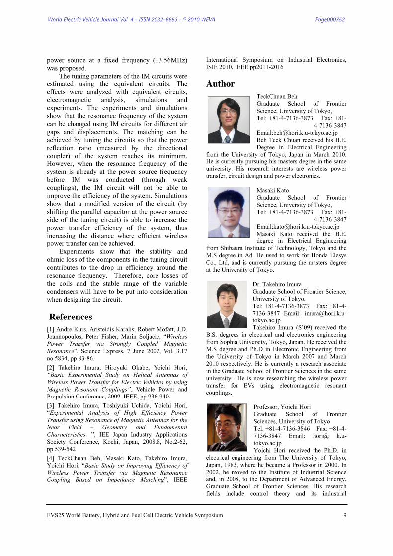
gap and displacement. To automate this system, the reflection ratio is measured and a computer will be used to select the tuning parameters (C1, C2) that will minimize the reflection ratio. It is important to know how the transmission and reflection ratio changes as the tuning parameters change so that a suitable searching algorithm and matching components can be chosen. In the event that local peak exists, a more sophisticated optimization algorithm such as the particle swarm optimization (PSO) will need to be applied instead of simple two dimension optimization algorithms such as the steepest gradient method.. The sharpness of the peak also determines the precision of the tuning parameters required. As two parameters are used, the system is a two dimension non linear system. Therefore, this simulation was conducted to study the capacitance range and precision needed by the matching parameters, and to check the system for local peaks. This simulation was run using Matlab to calculate the S21 parameter of the equivalent circuit in Fig. 7a. The inductor L0 set at 6000nH, and the coupling coefficient k varying from 0.05 (large gap) to 0.25(small gap).
Fig. 16 shows the S21 characteristics of the system at 13.56MHz when the tuning parameters C1 and C2 are varied from 10pF to 100pF. Based on the figure, it can be observed that 100pF variable condensers will be sufficient to tune the antennas. It also shows that the S21 parameter has a single peak with relatively gentle slopes at strong couplings (close range) and steeper slopes at weaker couplings (far range). This means that almost any optimizing algorithm can be used to tune the system as long as the precision of the parameters are sufficiently high. In this case, a precision of 1-2pF will be sufficient to satisfactorily tune the system.
(a) k=0.05
(b) k=0.17
(c) k=0.25 Figure 16: Characteristics of wave transmission ratio
S21 (C1, C2) at different coupling factor k.
6. Conclusion A wireless power transfer system based on
magnetic resonance coupling is proposed to as method to charge EVs. The frequency characteristics and the power transfer efficiency of the antennas were studied using equivalent circuits, electromagnetic analysis, simulations and experiments. The resonance frequency of the antennas changes as the air gap changes. Since the maximum power transfer efficiency occurs at the resonance frequency, the resonance frequency must match the frequency of the power source. When this is applied in the MHz range (which allows smaller size antennas), the usable frequency range is bounded by the ISM band. Therefore, a system which uses an IM network to match the resonant frequency of the antennas to a
World Electric Vehicle Journal Vol. 4 - ISSN 2032-6653 - © 2010 WEVA Page000751
EVS25 World Battery, Hybrid and Fuel Cell Electric Vehicle Symposium 9
power source at a fixed frequency (13.56MHz) was proposed.
The tuning parameters of the IM circuits were estimated using the equivalent circuits. The effects were analyzed with equivalent circuits, electromagnetic analysis, simulations and experiments. The experiments and simulations show that the resonance frequency of the system can be changed using IM circuits for different air gaps and displacements. The matching can be achieved by tuning the circuits so that the power reflection ratio (measured by the directional coupler) of the system reaches its minimum. However, when the resonance frequency of the system is already at the power source frequency before IM was conducted (through weak couplings), the IM circuit will not be able to improve the efficiency of the system. Simulations show that a modified version of the circuit (by shifting the parallel capacitor at the power source side of the tuning circuit) is able to increase the power transfer efficiency of the system, thus increasing the distance where efficient wireless power transfer can be achieved.
Experiments show that the stability and ohmic loss of the components in the tuning circuit contributes to the drop in efficiency around the resonance frequency. Therefore, core losses of the coils and the stable range of the variable condensers will have to be put into consideration when designing the circuit.
References [1] Andre Kurs, Aristeidis Karalis, Robert Mofatt, J.D. Joannopoulos, Peter Fisher, Marin Soljacic, “Wireless Power Transfer via Strongly Coupled Magnetic Resonance”, Science Express, 7 June 2007, Vol. 3.17 no.5834, pp 83-86. [2] Takehiro Imura, Hiroyuki Okabe, Yoichi Hori, “Basic Experimental Study on Helical Antennas of Wireless Power Transfer for Electric Vehicles by using Magnetic Resonant Couplings”, Vehicle Power and Propulsion Conference, 2009. IEEE, pp 936-940. [3] Takehiro Imura, Toshiyuki Uchida, Yoichi Hori, “Experimental Analysis of High Efficiency Power Transfer using Resonance of Magnetic Antennas for the Near Field – Geometry and Fundamental Characteristics- ”, IEE Japan Industry Applications Society Conference, Kochi, Japan, 2008.8, No.2-62, pp.539-542 [4] TeckChuan Beh, Masaki Kato, Takehiro Imura, Yoichi Hori, “Basic Study on Improving Efficiency of Wireless Power Transfer via Magnetic Resonance Coupling Based on Impedance Matching”, IEEE
International Symposium on Industrial Electronics, ISIE 2010, IEEE pp2011-2016
Author TeckChuan Beh Graduate School of Frontier Science, University of Tokyo, Tel: +81-4-7136-3873 Fax: +81-
4-7136-3847 Email:[email protected] Beh Teck Chuan received his B.E. Degree in Electrical Engineering
from the University of Tokyo, Japan in March 2010. He is currently pursuing his masters degree in the same university. His research interests are wireless power transfer, circuit design and power electronics.
Masaki Kato Graduate School of Frontier Science, University of Tokyo, Tel: +81-4-7136-3873 Fax: +81-
4-7136-3847 Email:[email protected] Masaki Kato received the B.E. degree in Electrical Engineering
from Shibaura Institute of Technology, Tokyo and the M.S degree in Ad. He used to work for Honda Elesys Co., Ltd, and is currently pursuing the masters degree at the University of Tokyo.
Dr. Takehiro Imura Graduate School of Frontier Science, University of Tokyo, Tel: +81-4-7136-3873 Fax: +81-4-7136-3847 Email: [email protected] Takehiro Imura (S’09) received the
B.S. degrees in electrical and electronics engineering from Sophia University, Tokyo, Japan. He received the M.S degree and Ph.D in Electronic Engineering from the University of Tokyo in March 2007 and March 2010 respectively. He is currently a research associate in the Graduate School of Frontier Sciences in the same university. He is now researching the wireless power transfer for EVs using electromagnetic resonant couplings.
Professor, Yoichi Hori Graduate School of Frontier Sciences, University of Tokyo Tel: +81-4-7136-3846 Fax: +81-4-7136-3847 Email: hori@ k.u-tokyo.ac.jp Yoichi Hori received the Ph.D. in
electrical engineering from The University of Tokyo, Japan, 1983, where he became a Professor in 2000. In 2002, he moved to the Institute of Industrial Science and, in 2008, to the Department of Advanced Energy, Graduate School of Frontier Sciences. His research fields include control theory and its industrial
World Electric Vehicle Journal Vol. 4 - ISSN 2032-6653 - © 2010 WEVA Page000752

EVS25 World Battery, Hybrid and Fuel Cell Electric Vehicle Symposium 10
applications to motion control, mechatronics, robotics, electric vehicles, etc. Prof. Hori was the recipient of the Best Paper Award from the IEEE Transactions on Industrial Electronics in 1993 and 2001 and of the 2000 Best Paper Award from the Institute of Electrical Engineers of Japan (IEEJ). He is the past President of the Industry Applications Society of the IEEJ, the President of the Capacitors Forum, and the Chairman of the Motor Technology Symposium of the Japan Management Association.
World Electric Vehicle Journal Vol. 4 - ISSN 2032-6653 - © 2010 WEVA Page000753