$evroxwh 0djqhwlf(qfrghu
TRANSCRIPT

®DATA SHEETMBD01_06 Issue 06, 20th May 2021
AksIM-2 is a non-contact, high performance off-axis absolute rotary encoder designed for integration into applications with limited space. A hollow ring, true absolute functionality and high-speed operation make this encoder suitable for many applications.The AksIM-2 encoder system consists of an axially magnetised ring and a readhead. The encoders are equipped with BiSS, Asynchronous serial (UART), SPI, PWM or SSI communication interfaces and offer a range of binary resolutions up to 20 bits per revolution.
Features and benefits
AksIM-2Off-Axis Rotary AbsoluteMagnetic Encoder
⯈ True absolute system
⯈ Custom magnetic sensor ASIC
⯈ Self-calibration option
⯈ No hysteresis
⯈ Resolution up to 20 bits
⯈ Multiturn counter option
⯈ High speed operation
⯈ Low profile, non-contact
⯈ Integrated status LED
⯈ High repeatability
COLLABORATIVE ROBOTS ROBOTIC JOINTSAGRICULTURAL AUTOMATIONGIMBALSAGVs
HIGH ACCURACY
HIGH SPEED
MULTITURN COUNTER

The AksIM-2 encoder operates in a temperature range between -40 °C and +105 °C and is highly resistant to shock and vibration. It has a built-in advanced self-monitoring function that continuously checks several internal parameters. Error reports, warnings and other status signals are available on all communication interfaces and visualised with the on-board LED.
The AksIM-2 encoder system is suitable for use in industrial and medical applications. A typical application is a robot arm joint with a cable feed through the ring, or a precision gearbox where the ring is mounted on the main transmission shaft.
A custom design service for OEM integration is also available. MB readheadMRA axial magnetic ring
+ =
AksIM-2 system
General information
Selection guide Magnetic ring Readhead
Part numberInner
diameterCircle for fasteners
Outer diameter Thickness
Inertia(kg × mm2)
Inner diameter
Circle for fasteners
Outer diameter Arc length
Max resolution
System thickness (Typ.) Mass (g)
MB022 Assembly
MB022 shape G 8.5 24 28.5 360° 17 bit 2.7
MRA022HP008DMN00 8 none 21.5 5.4 0.36 12.45 7.0
MB029 Assembly
MB029 shape F 14 35.4 38 360° 18 bit 4.5
MRA029BC010DSE00 10 15 29 2.0 0.75 7.85 5.9
MRA029GP013DMN00 12.7 none 29 7.0 1.0 12.85 9.0
MB039 Assembly
MB039 shape E 23 49 54 196° 19 bit 4.8
MRA039BC020DSE00 20 25 39 2.0 2.3 7.85 9.2
MB049 Assembly
MB049 shape D 34 54 59 190° 19 bit 4.5
MB049 shape E 26 54 59 138° 19 bit 4.2
MRA049BC025DSE00 25 31 49 2.0 5.5 7.85 15
MRA049AF025EMH00 25 31 49 3.9 13 9.75 32
MRA049BG034DSN00 34 none 49 2.0 4.8 7.85 11
MB053 Assembly
MB053 shape E 36 66 74 130° 20 bit 5.3
MRA053BC030DSE00 30 36 53 2.0 7.4 7.85 16
MRA053BG040DSN00 40 none 53 2.0 5.9 7.85 11
MB064 Assembly
MB064 shape D 48 69 74 140° 20 bit 6.9
MRA064BC040DSE00 40 46 64 2.0 15 7.85 20
MB080 Assembly
MB080 shape D 64.4 85 90 97° 20 bit 4.0
MRA080BC055DSE00 55 61.5 80 2.0 32 7.85 26
MRA080AF055EMH00 55 61.5 80 3.9 74 9.75 64
MRA080BG064DSN00 64 none 80 2.0 12.8 6.05 19
MRA080DF068DMH00 68 88 95 4.9 114 10.75 72
2
DATA SHEETMBD01_06

Storage and handling
The magnetic ring should not be exposed to magnetic field densities higher than 50 mT on its surface, as this can damage the ring.
–40 °C to +105 °C –40 °C to +105 °C–40 °C to +85 °C (MB022 only)
PackagingThere are two packaging options. Less than 20 products are packed individually in an antistatic box. If more than 20 systems are ordered, the parts are packed in antistatic plastic trays. Magnetic rings and readheads are packed separately.
Bulk packaging:
HANDLE WITH CARE. This encoder system is a high performance metrology product and should be treated with the same care as any other precision instrument. Use of heavy duty industrial tools or exposure to strong magnets, such as a magnetic base, is unacceptable and risks of irreparable damage to the product.
Readheads
Part Tray size Box size
MB022 - (individually) - (individually)
MB029 18 units per tray
10 trays per box
MB039 16 units per tray
MB049-E 20 units per tray
MB049-D 16 units per tray
MB05312 units per tray
MB064-E
MB064-D 10 units per tray
MB080 15 units per tray
Magnetic rings
Part Tray size Box size
MRA022 - (individually) - (individually)
MRA029
10 units per tray 12 trays per box
MRA039
MRA049-D
MRA049-E
MRA053
MRA064-E
5 units per tray 12 trays per boxMRA064-D
MRA080
Readhead is ESD sensitive - handle with care. Do not touch electronic circuit, wires or sensor area without proper ESD protection or outside of ESD controlled environment.
Storage temperature Operating temperature Humidity
🌡 🌡 🌢Up to 70 % non-condensing
3
®
A associate company

Encoder assembly MB022 readhead with MRA022HP008DMN00 magnetic ring
Dimensions and installation drawingsDimensions and tolerances are in mm.
Detail A
R14.25 ±0.1 R4.25 ±0.1
6.2 ±0.3
A
1.6 ±0.2
Mounting dimension6.25 ±0.10
Ride height0.20 ±0.15
5.40 ±0.05
Detail A
0.05 A
A
8 H6 + 0.0090
21.5 ±0.1
MB022 modul in MRA022HP008DMN00 ring
Ride height influences noise on the output. See chapter Installation instructions for details.
4
DATA SHEETMBD01_06

MB022 readhead
110
° 1
2 ±1
4.2
4.2
R12
20°
Sensor
Mounting surface (gold)
R14.25 ±0.1
R4.25 ±0.1
8.5 8.5
8.5
8
.5
3× Ø1.7 ThruØ3.4 Metallization
Pin 1
Zero position mark
MB022 modul
MRA022HP008DMN00 magnetic ring
8 H6 + 0.0090
21.5 ±0.1
14
5.40 ±0.05 3
MRA022HP008DMN00 ring
Dimensions and installation drawings continued
Press-fit mounting to shaft D8: recommended shaft OD tolerance is r6 (+0.019 / +0.028)
5
®
A associate company

R7 ±0.1 R19 ±0.1
5.2 ±0.3
A
1.6 ±0.2
Mounting dimensionM.D. ±0.15
Ride height0.2 ±0.15
2 ±0.05
Detail A
0.05 A
A
10 H7 + 0.0150
29 ±0.1
MB029 readhead with MRA029BC010DSE00 ringEncoder assembly MB029 readhead with MRA029BC010DSE00 magnetic ring
Detail AMounting dimension:
Ring part number M. D.
MRA029BC010DSE00 2.85 ±0.10
MRA029GP013DMN00 7.85 ±0.10
Dimensions and installation drawings continued
Ride height influences noise on the output. See chapter Installation instructions for details.
6
DATA SHEETMBD01_06

MB029 readhead
14.5
R16.6
R15
2x 49°
131
°
Sensor
Mounting surface (gold)
3x 4.2 Thru4.2 Metalization
R7 ±0.1 R19 ±0.1
11
16.
6
12.5 12.5
Pin 1
Zero position mark 14.5
R16.6
R15
2x 49°
131
°
Sensor
Mounting surface (gold)
3x 4.2 Thru4.2 Metalization
R7 ±0.1 R19 ±0.1
11
16.
6 12.5 12.5
Pin 1
Zero position mark
MRA029GP013DMN00 magnetic ring
MRA029BC010DSE00 magnetic ring
10 H7 + 0.0150
15
29 ±0.1
4x For fastenersM2 ISO 7046
2 ±0.05 1.2
12.7 H5 + 0.0080
29 ±0.05 7 ±0.05
4.6
15
.8
MRA029GP013DMN00 ring
MRA029BC010DSE00 ring
10 H7 + 0.0150
15
29 ±0.1
4x For fastenersM2 ISO 7046
2 ±0.05 1.2
12.7 H5 + 0.0080
29 ±0.05 7 ±0.05
4.6
15
.8
MRA029GP013DMN00 ring
MRA029BC010DSE00 ring
Dimensions and installation drawings continued
Press-fit mounting to shaft D8: recommended shaft OD tolerance is p7 (+0.018 / +0.036)
7
®
A associate company

196° ±0.2°
R27 ±0.1
R10.6 ±0.1
20 H7 +0.021
0
39 ±0.1
5.2 ±0.3
A
Ride height0.2 ±0.15
Mounting dimension2.85 ±0.10
1.6 ±0.2
2 ±0.05
Detail A
0.05 A
A
196° ±0.2°
R27 ±0.1
R10.6 ±0.1
20 H7 +0.021
0
39 ±0.1
5.2 ±0.3
A
Ride height0.2 ±0.15
Mounting dimension2.85 ±0.10
1.6 ±0.2
2 ±0.05
Detail A
0.05 A
A
Encoder assembly MB039 readhead with MRA039BC020DSE00 magnetic ring
Detail A
Dimensions and installation drawings continued
Ride height influences noise on the output. See chapter Installation instructions for details.
8
DATA SHEETMBD01_06

MB039 readhead 3x 60°
R20
R24.5
15
23 2
3°
Sensor
Mounting surface (gold)
R27 ±0.1 R10.6 ±0.1
196° ±0.2°
4x 2.2 THRUØ4.2 Metallization
Pin 1
Zero position mark
MRA039BC020DSE00 magnetic ring
20 H7 +0.021
0
25
39 ±0.1
8x For fastenersM2.5 ISO 7046
1.2
2 ±0.05
Dimensions and installation drawings continued
9
®
A associate company

R29.5 ±0.1
R17 ±0.1
25 H7 +0.021
0
49 ±0.1
190° ±0.2°
5.2 ±0.3
A
Ride height0.2 ±0.15
Mounting dimensionM.D. 0.10
1.6 ±0.2 2 ±0.05
Detail A
0.05 A
A
25 H7 +0.021
0
49 ±0.1
R29.5 ±0.1
R13 ±0.1
138°
±0.2°
R29.5 ±0.1
R17 ±0.1
25 H7 +0.021
0
49 ±0.1
190° ±0.2°
5.2 ±0.3
A
Ride height0.2 ±0.15
Mounting dimensionM.D. 0.10
1.6 ±0.2 2 ±0.05
Detail A
0.05 A
A
25 H7 +0.021
0
49 ±0.1
R29.5 ±0.1
R13 ±0.1
138°
±0.2°
Encoder assembly MB049 readhead shape D and readhead shape E with MRA049BC025DSE00 magnetic ring
Detail A
Mounting dimension:
Ring part number M. D.
MRA049BC025DSE00 2.85 ±0.10
MRA049AF025EMH00 4.75 ±0.10
MRA049BG034DSN00 2.85 ±0.10
Dimensions and installation drawings continued
Ride height influences noise on the output. See chapter Installation instructions for details.
10
DATA SHEETMBD01_06

MB049 readhead shape D
R25
R27
15
4x 45° 2
3°
28
Mounting surface (gold)
Sensor
R17 ±0.1
R29.5 ±0.1
5x 2.2 THRU4.2 Metallization
190
° ±0.
2°
Pin 1
Zero position mark
R29.5 ±0.1 R13 ±0.1
138
° ±0.
2°
3x 2.2 THRU4.2 Metallization
Zero position mark
Pin 1
R27
R25
15
2x 45°
28 23°
Mounting surface (gold)
Sensor
MB049 readhead shape E
R25
R27
15
4x 45°
23°
28
Mounting surface (gold)
Sensor
R17 ±0.1
R29.5 ±0.1
5x 2.2 THRU4.2 Metallization
190
° ±0.
2°
Pin 1
Zero position mark
R29.5 ±0.1 R13 ±0.1
138
° ±0.
2°
3x 2.2 THRU4.2 Metallization
Zero position mark
Pin 1
R27
R25
15
2x 45°
28 23°
Mounting surface (gold)
Sensor
Dimensions and installation drawings continued
11
®
A associate company

MRA049BC025DSE00 Magnetic ring
MRA049BG034DSN00 magnetic ring
MRA049AF025EMH00 magnetic ring
25 H7 +0.021
0
31 49 ±0.1
4x For fastenersM2.5 ISO 7046
34 H7 +0.025
0
49 ±0.1
25 H7 +0.021
0
49 ±0.1 31
30°
6x 2.95.5 1.8
3 +0.05
0 X 5
2x R1.5
16
3
3.9 ±0.05
2 ±0.05
1.2
2 ±0.05
1.2
25 H7 +0.021
0
31 49 ±0.1
4x For fastenersM2.5 ISO 7046
34 H7 +0.025
0
49 ±0.1
25 H7 +0.021
0
49 ±0.1 31
30°
6x 2.95.5 1.8
3 +0.05
0 X 5
2x R1.5
16
3
3.9 ±0.05
2 ±0.05
1.2
2 ±0.05
1.2
25 H7 +0.021
0
31 49 ±0.1
4x For fastenersM2.5 ISO 7046
34 H7 +0.025
0
49 ±0.1
25 H7 +0.021
0
49 ±0.1 31
30°
6x 2.95.5 1.8
3 +0.05
0 X 5
2x R1.5
16
3
3.9 ±0.05
2 ±0.05
1.2
2 ±0.05
1.2
Dimensions and installation drawings continued
12
DATA SHEETMBD01_06

MB053 readhead shape E
R37 ±0.1
R18 ±0.1
130° ±0.2°
30 H7 + 0.0210
53 ±0.1
5.2 ±0.3
A
2 ±0.05
Ride height0.2 ±0.15
1.6 ±0.2
Mounting dimension2.85 ±0.10
Detail A
0.05 A
A
MB053 readhead size E with MRA053BC030DSE00 ring
15
R33
R27.5
2x 60°
20°
31
Mounting surface (gold)
Sensor
130°
±0.2°
3x 2.2 THRU4.2 Metallization
R18 ±0.1
R37 ±0.1
Zero position mark
Pin 1
MB053 readhead size E
Encoder assembly MB053 readhead shape E with MRA053BC030DSE00 magnetic ring
Detail A
Mounting dimension:
Ring part number M. D.
MRA053BC030DSE00 2.85 ±0.10
MRA053BG040DSN00 2.85 ±0.10
Dimensions and installation drawings continued
Ride height influences noise on the output. See chapter Installation instructions for details.
13
®
A associate company

MRA053BC030DSE00 magnetic ring
MRA053BG040DSN00 magnetic ring
30 H7 + 0.0210
36
53 ±0.1
8x For fastenersM2.5 ISO 7046
2 ±0.05
1.2
40 H7 + 0.0250
53 ±0.1
1.2
2 ±0.05
MRA053BC030DSE00 ring
MRA053BG040DSN00 ring
30 H7 + 0.0210
36
53 ±0.1
8x For fastenersM2.5 ISO 7046
2 ±0.05
1.2
40 H7 + 0.0250
53 ±0.1
1.2
2 ±0.05
MRA053BC030DSE00 ring
MRA053BG040DSN00 ring
Dimensions and installation drawings continued
14
DATA SHEETMBD01_06

MB064 readhead shape D
Encoder assembly MB064 readhead shape D with MRA064BC040DSE00 magnetic ring
40 H7 + 0.0250
64 ±0.1
R37 ±0.1
R24 ±0.1
140° ±0.2°
5.2 ±0.3
A
2 ±0.05
Ride height0.2 ±0.15
Mounting dimension2.85 ±0.10
1.6 ±0.2
Detail A
0.05 A
A
MB064 readhead size D withMRA064BC040DSE00 ring
40 H7 + 0.0250
64 ±0.1
R37 ±0.1
R24 ±0.1
140° ±0.2°
5.2 ±0.3
A
2 ±0.05
Ride height0.2 ±0.15
Mounting dimension2.85 ±0.10
1.6 ±0.2
Detail A
0.05 A
A
MB064 readhead size D withMRA064BC040DSE00 ring
40 H7 + 0.0250
64 ±0.1
R37 ±0.1
R24 ±0.1
140° ±0.2°
5.2 ±0.3
A
2 ±0.05
Ride height0.2 ±0.15
Mounting dimension2.85 ±0.10
1.6 ±0.2
Detail A
0.05 A
A
MB064 readhead size D withMRA064BC040DSE00 ring
140° ±0.2°
R24 ±0.1
R37 ±0.1
4x 2.24.2 Metallization
Pin 1
Zero position mark
15
40°
52°
40°
R32
R34.5
34
20° Mounting surface (gold)
Sensor
MB064 readhead size D
Detail A
Dimensions and installation drawings continued
Ride height influences noise on the output. See chapter Installation instructions for details.
15
®
A associate company

MRA064BC040DSE00 magnetic ring
8x For fastenersM2.5 ISO 7046
40 H7 + 0.0250
64 ±0.1 46
2 ±0.05
1.2
MRA064BC040DSE00 ringDimensions and installation drawings continued
16
DATA SHEETMBD01_06

Encoder assembly MB080 readhead with MRA080BC055DSE00 magnetic ring
Detail A
97° ±0.2°
R45 ±0.1
R32.2 ±0.1
55 H7 + 0.0300
80 ±0.1
5.2 ±0.3
A
1.6 ±0.2
Ride height0.2 ±0.15
2 ±0.05
Mounting dimensionM.D. 0.1
Detail A
0.05 A
A
MB080 readhead withMRA080BC055DSE00 ring
97° ±0.2°
R45 ±0.1
R32.2 ±0.1
55 H7 + 0.0300
80 ±0.1
5.2 ±0.3
A
1.6 ±0.2
Ride height0.2 ±0.15
2 ±0.05
Mounting dimensionM.D. 0.1
Detail A
0.05 A
A
MB080 readhead withMRA080BC055DSE00 ring
Mounting dimension:
Ring part number M. D.
MRA080BC055DSE00 2.85 ±0.1
MRA080AF055EMH00 4.75 ±0.1
MRA080BG064DSN00 2.85 ±0.1
MRA080DF068DMH00 5.75 ±0.1
Dimensions and installation drawings continued
Ride height influences noise on the output. See chapter Installation instructions for details.
17
®
A associate company

MRA080AF055EMH00 magnetic ring
80
±0.
1
55
H7
+ 0.03
00
61
.5
8x For fastenersM2.5 ISO 7046
2 ±0.05
1.2
55
H7
+ 0.03
00
80
-0 0.03
61
.5
6x 2.9 5.5 1.8
2x R1.5
3 + 0.050 X 5
31 3 3.9 ±0.05
68
.5 H
7 + 0.
030
0
95
- -0.03
0.07
88
6x 2.9
2x R1.5
3 + 0.050 X 5
44
4.9 ±0.05
1.67
MRA080BC055DSE00 ring
MRA080AF055EMH00 ring
MRA080DF068DMH00 ring
MRA080BC055DSE00 magnetic ring
80 ±
0.1
55
H7
+ 0.03
00
61
.5
8x For fastenersM2.5 ISO 7046
2 ±0.05
1.2
55
H7
+ 0.03
00
80
-0 0.03
61
.5
6x 2.9 5.5 1.8
2x R1.5
3 + 0.050 X 5
31 3 3.9 ±0.05
68
.5 H
7 + 0.
030
0
95
- -0.03
0.07
88
6x 2.9
2x R1.5
3 + 0.050 X 5
44
4.9 ±0.05
1.67
MRA080BC055DSE00 ring
MRA080AF055EMH00 ring
MRA080DF068DMH00 ring
MB080 readhead
97° ±0.2°
R45 ±0.1
R32.2 ±0.1
4x 2.14.2 Matallization
Zero position mark
Pin 1
15
3x 30°
44
R41
R42.5
15° Mounting surface (gold)
Sensor
MB080 readhead
Dimensions and installation drawings continued
18
DATA SHEETMBD01_06

MRA080DF068DMH00 magnetic ring
MRA080BG064DSN00 magnetic ring 80
±0.
1
55
H7
+ 0.03
00
61
.5
8x For fastenersM2.5 ISO 7046
2 ±0.05
1.2
55
H7
+ 0.03
00
80
-0 0.03
61
.5
6x 2.9 5.5 1.8
2x R1.5
3 + 0.050 X 5
31 3 3.9 ±0.05
68
.5 H
7 + 0.
030
0
95
- -0.03
0.07
88
6x 2.9
2x R1.5
3 + 0.050 X 5
44
4.9 ±0.05
1.67
MRA080BC055DSE00 ring
MRA080AF055EMH00 ring
MRA080DF068DMH00 ring
64
H7
+ 0.03
00
80
±0.
1
2 ±0.05
1.2
MRA080BG064DSN00 ring
Dimensions and installation drawings continued
19
®
A associate company

Axial position adjustment (ride height)
The distance between the sensor and the ring should be between 0.05 mm and 0.35 mm. See detail A on dimension drawings of encoder assemblies. Using the gold-plated surface on the bottom as a reference surface for mounting the readhead is recommended. If the top side of the readhead is used as a reference surface, note that the thickness tolerance of the readhead must be taken into account.
The integrated LED can be used as an indicator. If the ride height is within the installation tolerances, the indicator LED will be green and will not change when the ring rotates. The center of the ring and the center of the readhead arc must be coaxial. The permissible eccentricity tolerances are given in the table below. Precise centering of the ring is essential, as the eccentricity of the ring mounting plays a major role in the overall accuracy.
Installation tolerances (readhead to ring)Axial displacement (ride height) See detail A on dimension drawings of encoder assemblies.
Tight ride height is recommended. Increasing the ride height exponentially increases encoder noise even if it is within installation tolerances. See chapter Resolutions.
Tangential displacement of the sensor ±0.3 mm
Radial displacement of the sensor MRA022: ±0.1 mmMRA029: ±0.3 mm MRA039: ±0.4 mm MRA049, MRA053, MRA064, MRA080: ±0.5 mm
Non-parallel mounting Tilt angle <0.2°
🎞 AksIM-2 installation video
The signal level information read out via communication interface can be used to calculate the ride height (distance between rubber on the ring and sensor on the readhead).
The value is proportional to the distance between the sensor and the ring. To calculate the real distance use the following formula: Ride height = K × Ln (SignalLevel) + NCalculated ride height has tolerance of ±20 µm.
Measuring ride height between the ring and the readhead
Encoder size K N
022, 029 –95.49 977.1
039, 049 –83.56 846.1
053, 064, 080 –71.62 682.0
K and N are selected depending on the encoder size.The SignalLevel value is available in the BiSS register at addresses 0x4E - 0x4F (see document MBD02 available at AksIM-2 website) and at the UART interface with command 'a' (see page 33).
Installation instructions
20
DATA SHEETMBD01_06

Ring / shaft fitEncoder accuracy
MRA022 MRA029 MRA039 MRA049 MRA053 MRA064 MRA080
H7/g6 worst case ±0.15° ±0.15° ±0.15° ±0.11° ±0.11° ±0.10° ±0.09°
H7/g6 average ±0.08° ±0.08° ±0.07° ±0.06° ±0.06° ±0.05° ±0.05°
After self-calibration N/A ±0.03° ±0.03° ±0.025° ±0.025° ±0.02° ±0.02°
Installation tolerances (ring to shaft)
Readhead is ESD sensitive - handle with care. Do not touch electronic circuit, wires or sensor area without proper ESD protection or outside of ESD controlled environment.
Pin 1
Connector Soldering pads BiSS CAsynchronous
serial SPI PWM SSI
1 1 5 V supply
2 2 0 V (GND)
3 Temperature sensor pin 1 *
4 Temperature sensor pin 2 *
5 3 MA+ RX Command in+ SCK Status out Clock+
6 4 MA– RX Command in– NCS - Clock–
7 5 SLO+ TX Data out+ MISO PWM out Data+
8 6 SLO– TX Data out– MOSI - Data–
Pinout
8-pin low profile connector FCI 10114830-11108LF
Counterpart mating connector:FCI 10114826-00008LFand 10114827-002LF
Soldering pads Dimensions: 2.54 x 1.14 mmwith 1.875 mm pitch
Soldering of the wires to the encoder must be done in accordance with IPC-A-610 Class 2 or 3 (or similar). Improper soldering will void the warranty.1 2 3 4 5 6
Electrical connections
* See chapter External isolated temperature sensor
See table of recommended tightening torques for RLS products (document TTD01) available at AksIM-2 website.
21
®
A associate company

Technical specifications
System dataReading type Axial reading
ResolutionFrom 17 bit to 20 bit and 16 bit multiturn counter option (see chapter Resolutions)
Maximum speed 10,000 RPM (for higher speeds contact RLS)
Encoder accuracy±0.05° / 180 arcsec (before installation - errors caused by mounting inaccuracy of the readhead, ring and drive shaft are not included)
Final system accuracyTyp. ±0.025° / 90 arcsec (after encoder self-calibration - see chapter Installation instructions). For accuracy up to ±0.005° / 18 arcsec contact RLS.
Hysteresis Less than unit of resolution
Repeatability Less than unit of resolution
Encoder speed 9 kHz bandwidth, 18 kHz sampling rate, up to 44 kHz refresh rate
Electrical dataSupply voltage (VDD) 4.5 V to 5.5 V at the connector. Rise time should be shorter than 20 ms.
Set-up time 100 ms (first data ready after supply voltage is in range), worst case: 200 ms
Current consumption Typ. 130 mA, max. 150 mA (without load on the outputs)
Connection 8-pin low-profile connector or soldering pads
Output loadRS422 ±40 mA
PWM, SPI 5 mA (LVTTL logic level)
ESD protection HBM, Class 2, ±2 kV (valid only on RS422 signals on connector; do not touch other components)
Mechanical dataAvailable ring sizes (inner diameter) 8 mm, 10 mm, 12.7 mm, 20 mm, 25 mm, 30 mm, 34 mm, 40 mm, 55 mm, 64
mm, 68 mm
Material type2 mm thick rings EN 1.4016 / AISI430 with glued CPE rubber filled with ferrite particles
3.9 mm and 4.9 mm thick rings
EN 1.4005 / AISI416 or EN 1.4104 / AISI430F with glued CPE rubber filled with ferrite particles
Mass, inertia See Selection table
Environmental data
Operating and storage temperature–40 °C to +105 °C (standard), Readhead MB022: –40 °C to +85 °C
Humidity Up to 70 % non-condensing (for higher contact RLS)
External magnetic field ±20 mT
Pressure Up to 600 bar with special option - See chapter Operation in high-pressure applications
Shock 100 G (6 ms, half-sine, EN 60068-2-27:2009)
Vibration 80 G (55 Hz - 2000 Hz, EN 60068-2-6:2008)
Environmental compliance RoHS, REACH
22
DATA SHEETMBD01_06

The LED provides visual feedback on signal strength, error status, and is used for setup and diagnostics.Flashing LED indicates that power is being supplied to the encoder, but communication has not been established. When communication is running at a rate of at least 5 readings per second, LED will be constantly lit.
LED signal Status
Green Normal operation; position data is valid.
Orange Warning; position is valid, but the resolution and/or accuracy might be out of specifi-cation. Some operating conditions are outside limits.
Red Error; position data is not valid.
Slow flashing Communication has not been established. Position was not requested within last 200 ms. Color of flashing - see above.
No light No power supply.
Continuously fast flashing red System error during start-up or operation.
3 s3 s3 s
3 sec. fast flashing Self-calibration result - see cchapter Self calibration after installation.
Status indicator LED
Chemical resistance
RLS products are often used in industrial applications and exposed to chemicals that can affect their internal and external components. While our products are designed to be resistant to many harsh chemicals and environments, long-term resistance will depend on exposure, temperature, and concentration. Most chemicals our products are exposed to are not in continuous contact. Therefore, a material that might not be resistant when submerged in a chemical will last indefinitely when wiped down by that same chemical once a day.CPE rubber on the ring does not withstand exposure to most mineral oils and greases.
For more information, or to confirm compatibility with a chemical in your environment, please contact RLS.
23
®
A associate company

1 2
254
508
8
2..253
Enco
der e
rror
[arc
sec]
Enco
der e
rror
[mde
g]
Harmonic number
Typical encoder error has some definite higher harmonic components. Example is from the MRA080 + MB080 encoder. Other encoder sizes have slightly different spectrum.
Accuracy of the encoder system
Precise centering of the ring is the key to good overall accuracy.By minimising the eccentricity of the ring assembly (using a gauge) and using a drive shaft with precision bearings, the error can typically be reduced to ±0.05° for MRA080 rings and ±0.06° for MRA049 rings.A typical accuracy diagram after good installation of MRA080 (without eccentricity) is shown in the diagram below.To improve accuracy after installation, we recommend to perform the self-calibration function.
Position [ ° ]200041 061 08108 001 02102 04 060
0.20.180.160.140.120.100.080.060.040.02
-0.02-0.04-0.06-0.08-0.10-0.12-0.14-0.16-0.18-0.2
023 043 063062 082 003022 042
Err
or [
° ]
0Erro
r [ °
]
Position [ ° ]
Higher harmonic components of the encoder error plot
Harmonic number
1 Eccentricity of the ring mounting
2 Oval shape of the ring
8 Number of mounting holes
2...253 Absolute code influence
254 SDE (offset)
508 SDE (amplitude, phase)
24
DATA SHEETMBD01_06

Self-calibration after installation
The self-calibration function eliminates the error caused by eccentricity, which is a dominant contributor to the accuracy of the encoder and is caused by the eccentric mounting of the ring. It cannot compensate for the magnetisation error between different rings. The Subdivisional Error (SDE) is negligible with AksIM. This function removes the error from one sine wave per revolution. The self-calibration function can be initiated by the user via selected communication interfaces or by using the appropriate USB encoder interface. Not available with PWM and SSI outputs. Refer to the description of the selected communication interface for details. When the multiturn counter is used in the encoder, it may have an incorrect value after self-calibration if the speed is greater than ±300 RPM. In such a case, the multiturn error flag is set.
Requirements: ⦁ Free mechanical rotation between 180° and 360° (the desired angle can be selected via the communication interface). ⦁ Good signal over the entire calibration angle. ⦁ Maximum time available is 10 seconds. ⦁ Variation of direction and speed are not important. Minimum speed is 6 RPM. ⦁ Suitable communication interface or adapter that enables the function to be triggered.
The graph below shows how much the accuracy of the encoder can be improved with the self-calibration function.The remaining minimum accuracy of ±0.02° is influenced by magnetisation variations and noise of the readhead.
When the self-calibration process is complete, fast-flashing LED indicates whether the process was successful.
Encoder system size 022 currently does not support self-calibration.
0 0.02 0.04 0.06 0.08 0.1 0.12 0.14
Eccentricity [mm]
0
0.05
0.1
0.15
0.2
0.25
0.3
0.35
0.4
0.45
Erro
r [°]
Remaining error after calibrationContribution of noiseError before calibration
LED Self-calibration status
Green flashing fast Self-calibration succesfully performed.
Orange flashing fastRing positioning is already perfect - correction was not performed. Status bit 0x20 is set.
Red flashing fastInput parameter out of range. Status bit 0x10 is set.Eccentricity or radial offset is very high. Status bit 0x08 is set.Timeout. Ring is rotating too slowly (<6 RPM). Status bit 0x04 is set.
🎞 Explainer video: AksIM-2 self-calibration feature.
25
®
A associate company

The operating principle of any magnetic encoder is to detect changes in the magnetic field of the magnetised ring. External magnetic fields generated by permanent magnets, electric motors, coils, magnetic brakes, etc. can affect the operation of the encoder. If external magnetic field is greater than 20 mT, it will temporarily cause the encoder to malfunction. Fields stronger than 50 mT may cause permanent damage to the ring.
Unwanted magnetic fields must be blocked at the source. If this is not possible, the encoder can be shielded with a ferromagnetic metal sheet. The ring can also be used for partial shielding. It is recommended that the bottom of the ring is mounted with the readhead facing away from the source of the escaping magnetic field. Contact RLS for more information.
Encoders provide two pass-through signals for connecting an external temperature sensor in an application. These can be Pt100, Pt1000, NTC, 1-wire or a similar low-voltage analogue or digital sensor. The signals are isolated from the encoder circuitry and are only routed from the “Temp. Sens.” pins of the connector to the solder pads where the external sensor is to be connected in an application.
The purpose of this is to provide temperature monitoring in applications such as electric motors, gearboxes, etc. where precise monitoring is required in the vicinity of the encoder. This solution simplifies cable management as the existing encoder cable can be used to transmit these two signals. The voltage must be limited to ±30 V relative to the other encoder signals and the current to ±500 mA.
The encoder can be configured to operate at ambient pressures of up to 600 bar. Typical applications include ROV submarines where the entire system is submerged in oil. A special version of the encoder must be used with the “P” option (see Part numbering). All frequencies must be reduced and timings increased by 12 %.
List of available part numbers: ⦁ MB029DCC18MFNP00 ⦁ MB049DCC19MDNP00 ⦁ MB080DCC17BDNP00 ⦁ MB080DCC20MDNP00
For more information or to confirm compatibility with a chemical in your environment, please contact RLS.
1 Temp. sens.
External magnetic field
External isolated temperature sensor
Operation in high-presure applications
26
DATA SHEETMBD01_06

BiSSClock frequency From 400 kHz to 5 MHz
Maximum request rate 44 kHz (38 kHz with multiturn counter option)
Mechanical sample rate 18 kHz
Bandwidth 9 kHz
Resolution See chapter Resolutions.
Latency <10 µs
Timeout (monoflop time) 13.5 µs
Asynchronous serial RS422 (UART)Baud rate 115.2 kbps, 128 kbps, 230.4 kbps, 256 kbps, 500 kbps, 921.6 kbps, 1 Mbps (Configurable
from 300 baud to 1 Mbaud)
Data format 8 bits, no parity, 1 stop bit
Request rate On demand or continuous
Mechanical sample rate 18 kHz
Bandwidth 9 kHz
Resolution See chapter Resolutions.
Latency <10 µs
SPIClock frequency Max 4 MHz
Maximum request rate 54 kHz (48 kHz with multiturn counter option)
Mechanical sample rate 18 kHz
Bandwidth 9 kHz
Resolution See chapter Resolutions.
Latency <10 µs
PWM*Base frequency 122.07 Hz, 274.66 Hz, 366.21 Hz, 549.32 Hz, 1098.63 Hz
Update rate Same as Base frequency
Resolution 16 bits
Latency From 55 µs to 110 µs
SSI* (Not recommended for new design)Clock frequency Minimum 80 kHz
Maximum 500 kHz with standard SSI (2.5 MHz with Delay First Clock function on the controller)
Mechanical sample rate 18 kHz
Resolution See chapter Resolutions.
Latency From 55 µs to 110 µs
Timeout (monoflop time) 20 µs
Communication interfaces
Interfaces with big or variable latency are not suitable for high-speed closed control loops. * SSI interface is supported for legacy applications and is not recommended for new design.
27
®
A associate company

The multiturn counter is available on the following communication interfaces: BiSS, Asynchronous serial (UART), SPI or SSI.The multiturn option is selected with the resolution in the Part numebring. The multiturn counter is 16 bits (0 to 65535 counts). Counting is only available when the encoder is powered, but the counter state is stored in a non-volatile memory at power-down and is restored at power-up. Maximum permissible rotation during power-down is ±90°. If the rotation is greater than this, the encoder reports an error to indicate an invalid multiturn counter value. To reset this condition, it is necessary to apply a new multiturn counter value via the communication interface or cycle power to the encoder. If encoder is rotated for ±360° or for multiple rotations, this movement is not registered and no multiturn error is set. If any other error is set during a rotation of 90° or more, the multiturn counter value may become inconsistent with the mechanical position.
The user must implement the multiturn counter validation method by either: ⦁ Activating the mechanical brake before the encoder goes into the power-down state and releasing the brake after the
encoder is powered-up ⦁ Presetting a new multiturn counter value each time the encoder is powered-up. ⦁ Other user-implemented multiturn counter validation methods.
Resolution MRA022 MRA029 MRA039, MRA049 MRA053, MRA064, MRA080
Binary 17 bits per revolution 17 bits per revolution18 bits per revolution *
17 bits per revolution18 bits per revolution *19 bits per revolution *
17 bits per revolution18 bits per revolution19 bits per revolution *20 bits per revolution *
* High resolution options may contain noise on the output. These resolutions are suitable for smoother operation of the control loops or averaging to obtain a fine position. The noise margin increases exponentially with increasing ride height between the ring and readhead.
Resolutions
Multiturn counter
Multiturn - shaft turn counter limitations
Counter may have invalid value in following circumstances:
Possible reasons for failure Solution
If encoder is rotated for ±360° or multiple rotations during off state. Use mechanical brake.
If Error flag (red LED) is present for 90° rotation or more. Read and evaluate Error bit.
When the encoder moves for 90° or more, or rotates 300 RPM or more when the encoder performs blocking operations (storing information in non-volatile memory, factory reset, write protect, self-calibration).
Stop rotation before performing these operations.
If user changes single-turn position offset for 90° or more. Set new multiturn counter value right after setting zero position offset.
If any function for storing information to non-volatile memory (save configuration, factory reset, write protect, self-calibration) is active when power-down happens.
Keep power supply stable when per-forming those operations.
Multiturn error flag
Error flag is set in one of the following conditions: ⦁ Detected movement of >90° and <270° when powered off, ⦁ Detected speed of more than 300 RPM during blocking operation, ⦁ High, unexpected positional difference detected (acceleration error)
Multiturn error bit can be cleared by writting new value into the encoder or by power cycle. On SSI interface only power cycle is available.
28
DATA SHEETMBD01_06

Latency on BiSS and Asynchronous serial (UART) and SPI interface
Latency on other type interfaces (SSI, PWM)
BiSS and UART use an algorithm that recalculates the new position for each request. In this way, the request frequency can be higher than the internal cycle frequency of the encoder. Normally, the request rate can be up to 44 kHz. The position is latched at the first falling edge on the MA (clock) line or the first bit of the command byte or on fallng edge of NCS signal and the new position value is calculated immediately, therefore the latency is shorter than 10 μs.
All interfaces transmit the last available valid data from the last internal cycle of the encoder. No additional recalculation takes place. The internal cycle of the encoder is 55 μs. This is the delay between the time the mechanical position is latched by the sensor and the time the data is ready for transmission via the interface.If the request comes immediately after the data is ready, the latency is 55 μs.If the request comes shortly before the new data is calculated, the latency is 110 μs.
Example:At t = 0 μs, the physical position is latched, but the position data is not yet calculated. It is then available at 55 μs.When the request comes at t = 1 μs – 54 μs, the last available data is sent - that from the previous cycle when the position was latched at t = –55 μs.
Latency
29
®
A associate company

BiSS C timing diagram
Encoder position in up to 20 bit natural binary code and encoder status are available via the BiSS C protocol. The position data is left aligned. The position data is followed by two status bits (active low) followed by CRC (inverted).
BiSS is implemented for point-to-point operation, multiple slaves are not supported.Communication is bidirectional, the readhead is user programmable and user defined parameters can be stored in the readhead and additional data can be read from the readhead.
* The MA and SLO lines are 5 V RS422 compatible differential pairs. The termination resistor on the MA line is integrated inside the encoder.
** Termination at the controller is required, if total cable length is longer than 5 m. The nominal impedance of the cable is 120 Ω.
Signals
MA Master clock. Max clock frequency is 5 MHz.
SLO Slave out. Data is output on rising edge on MA.
MA is idle high. Communication is initiated with first falling edge.The encoder responds by setting SLO low on the second rising edge on MA. ACK length is 13 bits.When the encoder is ready for the next request cycle, it indicates this to the master by setting SLO high.The absolute position and the CRC data is available in binary format and is first sent in MSB format.
Output protection
An excessive output current and power dissipation caused by errors or bus conflicts are prevented by two mechanisms. A foldback current limit on the output stage provides immediate protection against short circuits. In addition, a thermal shutdown circuit forces the driver outputs into a high-impedance state, if the chip temperature becomes too high.
Cable length compensation
The readhead requires 170 ns to respond to incoming clocks (tRESP). The change on the Data signal is delayed by 170 ns after the rising edge on Clock line. An additional delay is caused by the time it takes for the signal needs to propagate through cable to the readhead and back (tPROP). This delay is typically 14 ns per 1 meter of cable. The total cable length from the encoder to the receiver must be considered.
BiSS C interface
Electrical connection
ENCODER CONTROLLER
Rt*
Rt**
GND GND
SLO
MAA
B
Z
Y
MA Y
Z
SLO
A
BSLO
MA
SLO
MA
ACK Start CDS Position (18 – 34 bits) Error Warn. CRC (6 bits) Timeout
Idle
tDELAY = tRESP + tPROP x cable length
Clock
Data
tRESP tSTABLE
The data signal must be stable before the value is latched. Therefore, if the cable is longer than 1 meter and a clock frequency higher than 2.5 MHz, this delay must be compensated in the receiver (controller) to which the encoder is connected.
30
DATA SHEETMBD01_06

Type Value 0 Value 1 Description
Error Position data is invalid. OK Error bit is active low. If low, the position is not valid.
Warning Position data is valid. OK Warning bit is active low. If low, the encoder operation is close to its limits. The position is still valid but the resolution and/or accuracy might be out of specification.
Status bits
Communication parametersCommunication interface variant in the part number defines the functionality of the encoder.
Communication interface variant Parameter Value
C
MA frequency Max. 5 MHz
ACK length 13 bit
Register access Yes
Parameter Value
Latency <10 µs (recalculated on every transmission)
Bandwidth * 9 kHz
Mechanical sample rate 18 kHz
Maximum request rate 44 kHz (38 kHz Multiturn counter option)
Timeout 13.5 µs
* Bandwidth parameter is the mechanical bandwidth. AksIM samples at 18 kHz, so mechanical changes that are appearing faster than 9 kHz cannot be detected on the output (Nyquist theorem). If the position request comes faster than the sampling frequency, the AksIM encoder recalculates the position at the time of the request based on the current ring velocity.
ResolutionMultiturn counter Position CRC (inverted)Error Status Warning Status
17B
0 bits
17 bits
1 bit 1 bit 6 bits18B 18 bits
19B 19 bits
20B 20 bits
17M
16 bits
17 bits
1 bit 1 bit 6 bits18M 18 bits
19M 19 bits
20M 20 bits
Data packet description
Data packet length depends on the resolution and can be from 25 to 44 bits long. It consists of 16 bits for the multiturn counter (if selected) and 17 to 20 bits of Position selected by (resolution), followed by 2 Status bits and 6 CRC bits (see table below).
Example: 18 bits of position + 2 status bits + 6 bits CRC = 26 bits long data packet. Polynomial for CRC calculation of position, error and warning data is: x6 + x1 + 1. Represented also as 0x43. It is inverted and transmitted MSB first.Example of calculation routine for 6-bit CRC can be found in the application note CRCD01 available for download at AksIM-2 website.How to decode BiSS data packet: see document E201D02 available fro download on E201 website.For more information regarding BiSS C protocol see biss-interface.com.
BiSS C interface continued
31
®
A associate company

Encoder programming
Encoder supports register access which allows setting zero position, running self-calibration function, configuring the encoder, reading signal level indicator, temperature, detailed status bits and electronic datasheet. It also allows storing up to 4 kB of user data into the encoder (eg. motor parameters, assembly data or similar).This additional information can be found in the "Application note: AksIM-2 BiSS C register access", document number MBD02 available for download at AksIM-2 website.
BiSS C interface continued
32
DATA SHEETMBD01_06

Encoder identification, position data and temperature are available with request-response type of communication over the asynchronous serial link. There are two unidirectional communication channels that form a full-duplex bidirectional data link. Each channel consists of a two wire differential twisted-pair connection conforming to the RS422 signalling standard. Data is transmitted LSB first; big-endian order.
Output protection
An excessive output current and power dissipation caused by faults or by bus contention are prevented by two mechanisms. A foldback current limit on the output stage provides immediate protection against short circuits. In addition, a thermal shutdown circuit forces the driver outputs into a high-impedance state if the chip temperature becomes too high.
Character length 8 bits
Parity None
Stop bits 1
Flow control None
Request rate Maximum achievable, depending on selected baud rate. Can be transmitted continuously without delays between packets.
Mechanical sample rate 18 kHz
Bandwidth * 9 kHz
Position latency <10 µs (recalculated on every transmission)
Communication parameters
Electrical connection
* The Command and Data signals are 5 V RS422 compatible differential pairs with RC termination inside the readhead.** Termination at the controller is required if total cable length is longer than 5 m. The nominal impedance of the cable is 120 Ω.
ENCODER CONTROLLER
GND GNDData
Command
Rt**
Rt*
Asynchronous serial communication interface over RS422 (UART)
* Bandwidth parameter is mechanical bandwidth. AksIM samples at 18 kHz therefore any mechanical changes that are appearing faster than 9 kHz are not detectable on the output (Nyquist theorem). If request for position comes faster than sampling frequency, AksIM encoder recalculates the position at the time of request based on current ring velocity. 9 kHz bandwidth is valid for high dynamic movements of 2 degrees or smaller.
33
®
A associate company

Communication interface variant A B C D E F G
Link speed (baud rate) in kbps 115.2 128 230.4 256 500 1,000 921.6
Link speed is selectable by the Communication interface variant in the part number:
Link speed setting can be changed in the field by following the procedure described in application note. See section Encoder programming.
There is no easy way to revert to factory settings. New settings are permanent until encoder is reprogrammed again with different settings.
Command (ASCII) Response
'1' '1' + 3 (5) bytes (Position + E/W bits)
'3' 3 (5) bytes (Position + E/W bits)
'd' 'd' + 3 (5) bytes (Position + E/W bits) + 2 bytes (Detailed status)
's' 's' + 3 (5) bytes (Position + E/W bits) + 3 bytes (Speed in RPM)
't' 't' + 3 (5) bytes (Position + E/W bits) + 1 byte (Sensor temperature in °C)
'a' 'a' + 3 (5) bytes (Position + E/W bits) + 2 bytes (Signal level)
'i' 'i' + 7 bytes (Self calibration status)
'v' 'v' + 58 bytes (Version info and serial number)
Encoder supports a range of commands to read position data and additional information. In case multiturn option is selected, number in brackets must be used.
Command '3' is used as a request for the shortest possible response. In this case, only 3 bytes (or 5 bytes in multiturn variant) of position with integrated general error and warning bits are replied.In case of any other command, the header byte, which should be equal to the command itself, is replied first. Then, regardless of the command, 3 bytes (or 5 bytes if multiturn) of position with Error and Warning bits are sent. After that additional bytes are transmitted that carry requested information. Returned header byte should be equal to the command and can be used to determine which data packet format has to be decoded. In case of incorrect command, only header byte is returned with no other data.
Position data structure for singleturn variant
Encoder resolution Position bits Zero padding bits Error bit, Warning bit
17B b23 – b7 b6 – b2 b1, b0 (both active low)
18B b23 – b6 b5 – b2 b1, b0 (both active low)
19B b23 – b5 b4 – b2 b1, b0 (both active low)
20B b23 – b4 b3 – b2 b1, b0 (both active low)
Position data packet structure
Position data consists of 3 bytes if singleturn variant is selected or 5 bytes if multiturn variant is selected. Encoder position is always left aligned and starts with multiturn data (if available). Error and warning bits are always right aligned (bit 1 and bit 0 respectively). Between LSB of position and error bit are padding bits with value 0. The structure of position data bytes for each encoder resolution is presented in the table below.
Asynchronous serial communication interface over RS422 (UART) continued
34
DATA SHEETMBD01_06

Position data structure for multiturn variant
Encoder resolution Position bits Zero padding bits Error bit, Warning bit
17M b39 – b7 b6 – b2 b1, b0 (both active low)
18M b39 – b6 b5 – b2 b1, b0 (both active low)
19M b39 – b5 b4 – b2 b1, b0 (both active low)
20M b39 – b4 b3 – b2 b1, b0 (both active low)
Error and warning bits integrated into position data are always transmitted inverted (active low). Value '0' on error bit means that the position is not valid. Value '0' on warning bit means position is valid, but the encoder is near operational limits. In case of error, the last valid data is transmitted.
Commands and their respective responses for singleturn versionFor multiturn add 2 bytes to the length of position data.
Command '1'
Byte transmitted Contents
B1 ASCII header '1'
B2 - B4 Position + E + W
Command '3'
Byte transmitted Contents
B1 - B3 Position + E + W
Command 'd'
Byte transmitted Contents
B1 ASCII header 'd'
B2 - B4 Position + E + W
B5 - B6 Detailed status (refer to table on next page)
Command 's'
Byte transmitted Contents
B1 ASCII header 's'
B2 - B4 Position + E + W
B5 - B7 (Signed binary) Rotational speed in RPM.
Command 't'
Byte transmitted Contents
B1 ASCII header 't'
B2 - B4 Position + E + W
B5 (Signed binary) Sensor temperature in °C. This value is typically 5 °C to 15 °C higher than ambient. Tolerance of readout is ±5 °C.
Command 'a'
Byte transmitted Contents
B1 ASCII header 'a'
B2 - B4 Position + E + W
B5 - B6 (Unsigned binary) Signal level Value is proportional to the distance between the sensor and ring. To calculate real distance see formula on page 22.
Asynchronous serial communication interface over RS422 (UART) continued
35
®
A associate company

Command 'i'
Byte transmitted Contents
B1 ASCII header 'i'
B2 Self calibration status - See document MBD03 available for download at AksIM-2 website
B3 - B4 (Unsigned binary) Ring eccentricity (µm)
B5 - B6 (Unsigned binary) Ring eccentricity phase (deg)
B7 - B8 (Unsigned binary) Readhead radial displacement (µm)
Command 'v'
Byte transmitted Contents
B1 ASCII header 'v'
B2 - B8 ASCII identification string 'AksIM-2'
B9 Space character
B10 - B17 ASCII serial number (8 characters)
B18 Space character
B19 - B34 ASCII part number (16 characters)
B35 Space character
B36 Binary firmware major version
B37 Binary firmware minor version
B38 Binary communication interface version
B39 - B42 Binary firmware revision number
B43 Space character
B44 - B59 ASCII extended serial number (16 characters)
Detailed status (part 1)
b15 Error - Multiturn counter mismatch. Encoder was rotated for more than ±90° during power-down. Cycle the power to clear this error or apply new multiturn counter value.
b14 Error - Signal amplitude too high. The readhead is too close to the ring or an external magnetic field is present.
b13 Warning - Signal amplitude too high. The readhead is too close to the ring or an external magnetic field is present.
b12 Error - Magnetic sensor error. Cycle power to the encoder.
b11 Error - Sensor reading error, probably caused by electrical interference, ground loop or RFI.
b10 Error - Encoder not configured properly.
General status
b9 Error. If bit is set, position is not valid.
b8 Warning. If bit is set, encoder is near operational limits. Position is valid. Resolution and / or accuracy might be lower than specified.
Error and Warning bits can be set at the same time; in this case Error bit has priority. The colour of the LED on the readhead housing indicates the value of the General status bits:
Red = Error, Orange = Warning, Green = Normal operation, No light = no power supply.The warning or error status is more closely defined by the Detailed status bits.
Structure of Detailed status bits (two bytes)
Asynchronous serial communication interface over RS422 (UART) continued
36
DATA SHEETMBD01_06

Encoder programming
Encoder supports changing default baud rate, running self-calibration function, reading signal level value, temperature, detailed status bits and setting automatic transmission of selected data packet at programmable frame rate. Additional information can be found in the "Application note: Programming encoders with Async serial interface", document number MBD03 available for download at AksIM-2 website.
Detailed status (part 2)
b7 Warning - Signal amplitude too high. The readhead is too close to the ring or an external magnetic field is present.
b6 Warning - Signal amplitude low. The distance between the readhead and the ring is too large.
b5 Error - Signal lost. The readhead is out of alignment with the ring or the ring is damaged.
b4 Warning - Temperature out of range. The readhead temperature is out of specified range.
b3 Error - Power supply error. The readhead power supply voltage is out of specified range.
b2 Error - System error. Malfunction inside the circuitry or inconsistent calibration data is detected. To reset the System error bit try to cycle the power supply while the rise time is shorter than 20 ms.
b1 Error - Magnetic pattern error. A stray magnetic field is present or metal particles are present between the readhead and the ring or radial positioning between the readhead and the ring is out of tolerances.
b0 Error - Acceleration error. The position data changed too fast. A stray magnetic field is present or metal particles are present between the readhead and the ring.
Asynchronous serial communication interface over RS422 (UART) continued
37
®
A associate company

The controller starts the communication by setting the NCS signal low. At the same time the encoder position is latched. A delay of tS is required to allow the encoder to prepare the data which is then shifted to MISO output on rising edges of clock signal SCK. Encoder Position and General Status (active low) data is transmitted, followed by CRC (inverted) of the entire data packet.
SPI timing diagram
b47Hi-Z Hi-Z
b30b31 b10 b9
Multi-turn counter
SCK
MOSI
MISO
NCS
tCL
b8
E+W
b7 b1 b0
CRCSingle-turn counter
tPtS
Electrical connection
All data signals are 3.3 V LVTTL. Inputs are 5 V tolerant. The maximum current sourced or sunk from signal lines should not exceed 5 mA. Single-ended signals should be as short as possible, especially when high frequencies are used.Signal termination: 100 Ω resistors are added in series with all SPI signals.
Signal Description
NCS
Active low. NCS line is used for synchronisation between master and slave devices. During communication it must be held low. Idle is high. When NCS is high, MISO line is in high-Z mode. This allows connection of multiple slaves in paralell, sharing all lines except NCS. Encoder position data is latched on falling edge of NCS signal.
SCK Serial clock. Shifts out the data on rising edge.
MOSIMaster output Slave input. Command from the controller to encoder. If only position data is requred, this signal should always be zero. It can be tied to GND.
MISOMaster input Slave output. Data is output on rising edge on SCK after NCS low. When NCS is high, MISO line is in high-Z mode.
ENCODER CONTROLLER
NCS
SCK
MOSI
MISO
The Serial Peripheral Interface (SPI) bus is a four-wire bidirectional synchronous serial communication interface, typically used for short distance communication. It operates in full duplex mode, where master (controller) selects the slave with NCS line, generates clock signal on SCK line, sends command over MOSI line and receives data over MISO line. AksIM-2 encoders provide either only position information via the SPI interface only or full register access via the EncoLink high-level protocol. For more information, refer to the document MBD08 available for download at AksIM-2 website.
SPI - Serial peripheral interface
38
DATA SHEETMBD01_06
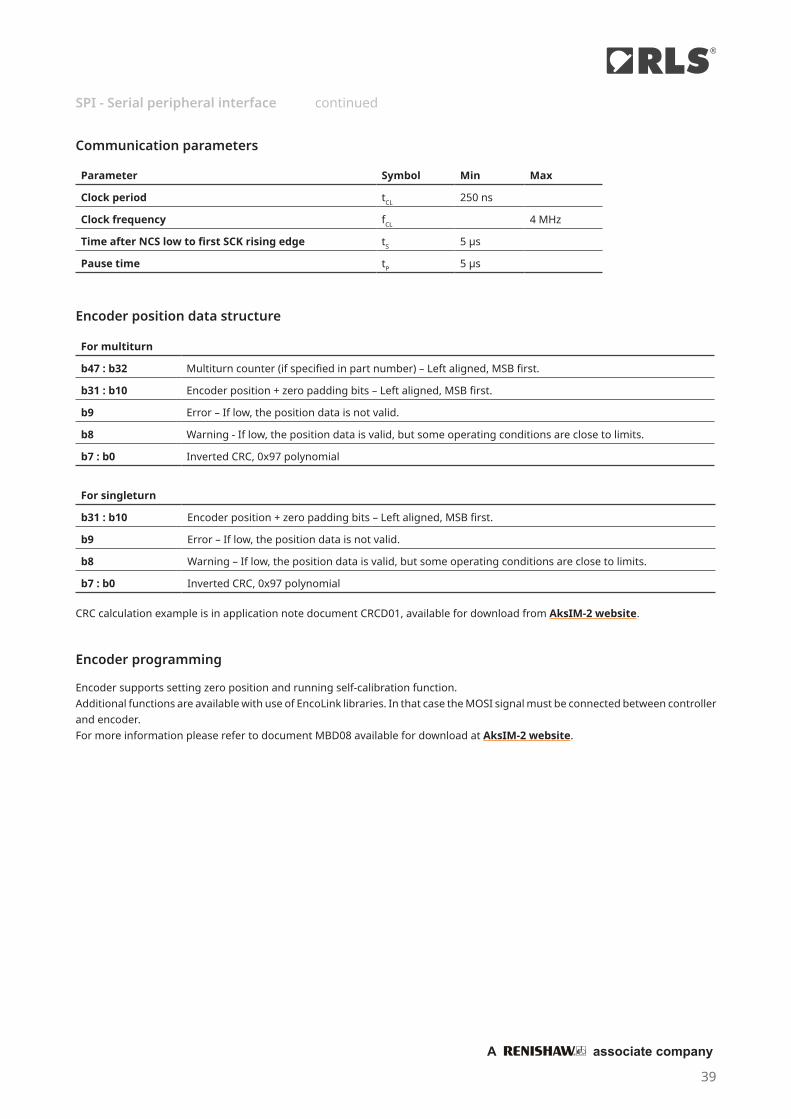
Encoder position data structure
Encoder programming
Encoder supports setting zero position and running self-calibration function.Additional functions are available with use of EncoLink libraries. In that case the MOSI signal must be connected between controller and encoder.For more information please refer to document MBD08 available for download at AksIM-2 website.
Communication parameters
Parameter Symbol Min Max
Clock period tCL 250 ns
Clock frequency fCL 4 MHz
Time after NCS low to first SCK rising edge tS 5 µs
Pause time tP 5 µs
For multiturn
b47 : b32 Multiturn counter (if specified in part number) – Left aligned, MSB first.
b31 : b10 Encoder position + zero padding bits – Left aligned, MSB first.
b9 Error – If low, the position data is not valid.
b8 Warning - If low, the position data is valid, but some operating conditions are close to limits.
b7 : b0 Inverted CRC, 0x97 polynomial
For singleturn
b31 : b10 Encoder position + zero padding bits – Left aligned, MSB first.
b9 Error – If low, the position data is not valid.
b8 Warning – If low, the position data is valid, but some operating conditions are close to limits.
b7 : b0 Inverted CRC, 0x97 polynomial
CRC calculation example is in application note document CRCD01, available for download from AksIM-2 website.
SPI - Serial peripheral interface continued
39
®
A associate company

The PWM communication interface consists of two digital signals: the Status signal and the PWM Out signal.
Electrical connection
The Status and PWM Out signals are 3.3 V TTL compatible. These signal outputs are weakly ESD protected, so the readhead must be handled with extra care and ESD protection in ESD controlled environment. Maximum current sourced from or sunk into signal lines should not exceed 5 mA.
Status signal
The Status signal indicates the current status of the encoder. The Status signal is high for normal operation and valid position information. The low state of the Status signal indicates an error state of the encoder which may be caused by:
⦁ Operation outside the installation tolerances ⦁ Invalid or damaged magnetization of the ring ⦁ Sensor malfunction ⦁ System error ⦁ No power supply
When the Status signal is low, the PWM Out signal is low and no pulses are output.The encoder position is latched on the rising edge of the PWM Out signal. The Status signal should also be checked at the rising edge of the PWM Out signal. If the Status signal changes during the PWM period, this has no effect on the currently transmitted position information. Status output signal is not linked to the PWM output cycle and is updated with each internal cycle of the encoder. Pulses can be present as short as 50 µs.
PWM Out signal
The PWM Out is a pulse width modulation output with 16-bit resolution whose duty cycle is proportional to the measured position. The change of the pulse width by PWmin corresponds to a position change by one count (angle change for 360° / 65536 ≈ 0.00549°).
PWM Out signal timing diagram
PWM Out signal
ton
tPWM = 1/fPWM
PWmin
Position 0 stepsAngle 0°
PWmax
Position 65535 stepsAngle 359.99451°
PWM - Pulse width modulation interface
40
DATA SHEETMBD01_06

Communication interface variant
Parameter Symbol A B C D E Unit Note
PWM frequency fPWM 122.07 274.66 366.21 549.32 1098.63 Hz
Signal period tPWM 8192 3640.89 2730.67 1820.44 910.22 μs
Minimum pulse width
PWmin 0.125 0.0556 0.0417 0.0278 0.0278 ** μs Position 0 (Angle 0°)
Maximum pulse width
PWmax 8191.875 3640.83 2730.63 1820.42 910.20 ** μs Positions 65534 and 65535 *
Min. counter fre-quency
fCNTR 8 18 24 36 72 MHz Receiving counter frequency
Resolution 16 Bit 16 Bit 16 Bit 16 Bit 16 Bit Fixed; resolution in part number must be set as "16B"
Position [counts] = - 1ton × 65536
tPWM
Position [°] = (ton - PWmin) × 360°
tPWM
Communication parameters
Communication interface variant in the part number defines the PWM frequency and all other dependent parameters.
* Positions 65535 and 65534 are joined together; readout as 65534 (PWmax).** At frequency 1099 Hz positions 0 and 1 are joined together; readout as 1 (PWmin). Positions 65535, 65534 and 65533 are joined together; readout as 65533 (PWmax).
PWM - Pulse with modulation interface continued
41
®
A associate company

Output protection
An excessive output current and power dissipation caused by errors or by bus conflicts are prevented by two mechanisms. A foldback current limitation at the output stage provides immediate protection against short circuits. In addition, a thermal shutdown circuit forces the driver outputs into a high-impedance state if the chip temperature becomes too high.
The controller queries the readhead for its position and status data by sending a pulse train to the Clock input. The Clock signal always starts from high. The first falling edge 1 latches the last available position data, and on the first rising edge 2 the most significant bit (MSB) of the position is transmitted to the Data output. The Data output should then be latched on the next falling edge. On the following rising edges of the Clock signal the next bits are transmitted. If the time between 1 and 2 is extended for additional 1 µs, the maximum clock frequency limit is 2 MHz instead of 500 kHz. This function is called "Delay First Clock" and must be supported by the controller to which the encoder is connected.
After the transmission of the last bit 3 the Data output goes to low. When the tM time expires the Data output is undefined 4 . The Clock signal must remain high for at least tM before the next reading can take place.
While reading the data the period tCL must always be less than tM. However, reading the encoder position can be terminated at any time by setting the Clock signal to high for the duration of tM.
SSI timing diagram
See table "Structure of data packet".
Clock
Data
Start MSB
1 2tCL
tDFC
IdleLSB
3 4
N-1 N-2 N-3 b3 b2 b1 b0
tM
SSI - Synchronous serial interface
Electrical connection
SSI interface is supported for legacy applications and is not recommended for new designs. The encoder position in up to 20 bit natural binary code and the encoder status are available via the SSI protocol. The position data is left aligned. The position data is followed by two general status bits, followed by the detailed status information. SSI interface is not recommended for closed-loop applications and motor feedback due to low update speed and noticeable (variable) latency.
* The Clock and Data signals are 5 V RS422 compatible differential pairs with RC termination inside the readhead.** Termination at the controller is required if total cable length is longer than 5 m. The nominal impedance of the cable is 120 Ω.
ENCODER CONTROLLER
Rt*
Rt**
GND GNDData
Clock
42
DATA SHEETMBD01_06

The power supply must be applied at least 100 ms before the clock sequence is being sent to the encoder.
tB
Maximum frequency
Clock
Data
tRESP tSTABLE
The readhead needs 170 ns to respond to incoming clocks (tRESP). Change on Data signal is delayed for 170 ns after the rising edge on Clock line. Additional delay is caused by the time the signal needs to propagate through cable to the readhead and back (tPROP). This delay is typically 14 ns per 1 meter of cable. Data signal must be stable for at least 10 % of the clock period length before the value is latched.The clock frequency must be reduced with a longer cable. Total cable length must be taken into account, from the encoder to the receiver.tDELAY = tRESP + tPROP × cable length
Frequency derating versus cable length:
Cable length [m]
1,0
0 10 20 30 40 50 60 70 80 90 1000
0.5
1
1.5
2.5
2
3
Max
. fre
quen
cy [M
Hz]
To allow updating of the position data at least tB should pass between two subsequent readings. If the reading request arrives earlier than tB after the previous reading, the encoder position will not be updated.
Parameter Symbol Min Typ Max
Delay first clock tDFC 1 µs 10 µs
Clock period tCL 2 µs 20 µs
Clock frequency fCL 50 kHz 500 kHz (2.5 MHz *)
Timeout (monoflop time) tM 20 µs
Request rate tB 70 µs
Readhead response delay tRESP 170 ns
Latency 55 µs 110 µs
Communication parameters
* With Delay First Clock function on the controller.
SSI - Synchronous serial interface continued
43
®
A associate company

Bit number
Singleturn resolution Multiturn counter* Encoder position General status Detailed status
20 bits b45 : b30 b29 : b10 b9 : b8 b7 : b0
19 bits b44 : b29 b28 : b10 b9 : b8 b7 : b0
18 bits b43 : b28 b27 : b10 b9 : b8 b7 : b0
17 bits b42 : b27 b26 : b10 b9 : b8 b7 : b0
Structure of data packet
Start bit and idle line value are defined by the Communication interface variant.
Communication interface variant Line state selection Usage
B Start bit = 1; idle line = 1 Standard
* If selected in part number
Multiturn counter (if selected in part number)
First 16 bits (see table above)
Multiturn counter - Occupying full 16 bits. Can be interpreted as signed number (±32768) or unsigned number (0 to 65535) that represents number of shaft turns.
Encoder position
Following 17 to 20 bits (see table above)
Encoder position – Left aligned, MSB first, LSB last.
General status
b9 Error bit. If set, the position is not valid.
b8 Warning bit. If set, the encoder operational is close to its limits. The position is still valid, but the resolution and/or accuracy might be out of specification.
The Error and Warning bits can be set at the same time, in this case the Error bit has priority.The colour of the LED on the readhead housing indicates the value of the General status bits:
Red = Error, Orange = Warning, Green = Normal operation, No light = No power supply.The warning or error status is more closely defined by the Detailed status bits.
Detailed status
b7 Warning - Signal amplitude too high. The readhead is too close to the ring or an external magnetic field is present.
b6 Warning - Signal amplitude low. The distance between the readhead and the ring is too large.
b5 Error - Signal lost. The readhead is out of alignment with the ring or the ring is damaged.
b4 Warning - Temperature. The readhead temperature is out of specified range.
b3 Error - Power supply error. The readhead power supply voltage is out of specified range.
b2Error - System error or Multiturn error. Malfunction inside the circuitry or inconsistent calibration data is detected. To reset the System error bit try to cycle the power supply while the rise time is shorter than 20 ms.
b1Error - Magnetic pattern error. A stray magnetic field is present or metal particles are present between the readhead and the ring or radial positioning between the readhead and the ring is out of tolerances.
b0Error - Acceleration error. The position data changed too fast. A stray magnetic field is present or metal particles are present between the readhead and the ring.
SSI - Synchronous serial interface continued
44
DATA SHEETMBD01_06

MB 049 DC C 18B D N T 00
SeriesMB - AksIM board-level readhead
MRA ring compatibility022 - For use with MRA022 ring029 - For use with MRA029 ring039 - For use with MRA039 ring049 - For use with MRA049 ring
Communication interfaceDC - BiSS C, RS422SF - Asynchronous serial, RS422SP - SPI (Serial peripheral interface),
LVTTL
Communication interface variantSee table next to the description of the chosen communication interface for detailed informationFor DC: C - Asynchronous serial, RS422For SC: B - SPI (Serial peripheral interface), LVTTL For SP: L - Pulse Width Modulation (PWM), LVTTL For SF: Link speed in kbps:
A B C D E F G115.2 128 230.4 256 500 1000 921.6
Special requirements00 - No special requrements (standard)
Connector optionN - FCI 10114830-11108LF, 8 pin connectorP - Soldering pads
OptionT - Extended temperature range (standard)L - Extended low temperature range, –40 °C to +85 °CP - High pressure (up to 600 bar)**
Shape and connector orientationD - Partial arc, radial connector exitE - Partial arc, tangential connector exitF - Full circle, radial connector exitG - Full circle, axial connector exit
Resolution16B - 16 bits per revolution17B - 17 bits per revolution18B - 18 bits per revolution19B - 19 bits per revolution20B - 20 bits per revolution
Multiturn counter options17M - 17 bits per revolution + 16 bits multiturn counter18M - 18 bits per revolution + 16 bits multiturn counter19M - 19 bits per revolution + 16 bits multiturn counter20M - 20 bits per revolution + 16 bits multiturn counter
Readhead
Part numbering
* Not recommended for new design
053 - For use with MRA053 ring064 - For use with MRA064 ring080 - For use with MRA080 ring
PW - Pulse Width Modulation (PWM), LVTTLSC - Synchronous serial interface (SSI), RS422 *
For PW: Base frequency in Hz:
A B C D E122 275 366 549 1099
** See chapter Operation in high-pressure applications.
Not all part number combinations are valid. Please refer to the table of available combinations on the next page.
45
®
A associate company

SeriesRing
compatibilityCommunication
interfaceCommunication interface variant Resolution
Shape & connector
orientationConnector
option Option Special
requirements
MB
022
DC C
17B / 17M G N L
00
SFA / B / C / D / E /
F / G
SC B
029
DC C
17B - 18B17M - 18M
F
N / P
TP *
SFA / B / C / D / E /
F / G
SP LN
PW A / B / C / D / E 16B
SC B17B - 18B17M - 18M
N / P
039
DC C
17B - 19B17M - 19M
E
SFA / B / C / D / E /
F / G
SP LN
PW A / B / C / D / E 16B
SC B
17B - 19B17M - 19M
N / P
049
DC C
D
SFA / B / C / D / E /
F / G
SP LN
PW A / B / C / D / E 16B
SC B
17B - 19B17M - 19M
N / P
DC C
E
NSFA / B / C / D / E /
F / G
SC B
053
DC C
17B - 20B17M - 20M
N / PSF
A / B / C / D / E / F / G
SP LN
PW A / B / C / D / E 16B
SC B
17B - 20B17M - 20M
N / P
064
DC C
D
SFA / B / C / D / E /
F / G
SP LN
PW A / B / C / D / E 16B
SC B
17B - 20B17M - 20M
N / P
080
DC C
SFA / B / C / D / E /
F / G
SP LN
PW A / B / C / D / E 16B
SC B17B - 20B17M - 20M
N / P
Table of available combinations
* Specific configurations only. See chapter Operation in high-pressure applications.
46
DATA SHEETMBD01_06

MRA 049 B C 025 D S E 00
SeriesMRA - AksIM magnetic ring
Outer diameter and readhead compatibility022 - 22 mm029 - 29 mm039 - 39 mm049 - 49 mm
Inner diameter008 - 8 mm010 - 10 mm013 - 12.7 mm020 - 20 mm
ThicknessA - 3.9 mmB - 2.0 mmD - 4.9 mm
Installation typeC - Countersunk fastenersF - Flat-head fastenersG - GlueP - Press-fit
Special requirements00 - No special requrements (standard)
MaterialM - Machined stainless steel hub with CPE rubberS - Stamped metal plate with CPE rubber
Zero markingE - EngravedH - HoleN - None
Accuracy gradeD - ±0.1°E - ±0.05°
Magnetic ring
053 - 53 mm064 - 64 mm080 - 80 mm
025 - 25 mm030 - 30 mm034 - 34 mm040 - 40 mm
G - 7 mmH - 5.4 mm
Not all part number combinations are valid. Please refer to the table of available combinations on the next page.
055 - 55 mm064 - 64 mm068 - 68 mm
47
®
A associate company

Table of available combinations
Series
Outer diameter and readhead compatibility Thickness
Installation type
Inner diameter
Accuracy grade Material Zero marking
Special requirements
MRA
022 H P 008
D
M N
00
029B C 010 S E
G P 013 M N
039 B C 020 S E
049
A F025
E M H
B
C
D S
E
G 034 N
053C 030
EG
040064 C N
080
A F055
E M H
BC
DS
E
G 064 N
D F 068 M H
Available ring part numbers:
MRA022HP008DMN00MRA029BC010DSE00MRA029GP013DMN00MRA039BC020DSE00MRA049AF025EMH00MRA049BC025DSE00MRA049BG034DSN00MRA053BC030DSE00MRA053BG040DSN00MRA064BC040DSE00MRA080AF055EMH00MRA080BC055DSE00MRA080BG064DSN00MRA080DF068DMH00
48
DATA SHEETMBD01_06

Accessories
USB interface (for BiSS C communication interface)E201-9B
USB interface (For SSI communication interface)E201-9S
Magnet viewerMM0001
Cable assemblyACC015
Cable assemblyACC016
49
®
A associate company

Cable assemblies
Compatible readhead Part number Length Connector 1 Connector 2 Notes
Every readhead with connector
option “N”
ACC0151.0 m
FCI 10114826-00008LF and
10114827-002LF
Flying leadsSingle-shielded
ACC016 DSUB-9 M
Cable specifications
Part numbers ACC015, ACC016
Cable specifications LI12YC12Y
Configuration 4 × 2 × 0.14 mm2 (twisted pairs)
Sheath colour Grey (RAL7032)
Rated voltage 250 V
Temperature range Moving –30 °C to +125 °C Static –40 °C to +130 °C Not valid for cables with DSUB-9 M connector.
Environmental compliance RoHS conform73/23/EWG-Guideline CE conformHalogen freeREACH compliant
Chemical resistance Largely resistant to acids, bases and usual oils.Free from lacquer damaging substances and silicone.
ACC016 can be used for direct connection to E201-9S or E201-9B USB encoder interface.
Dimensions in mm.
Connector 1 Connector 2
1000
appr
ox. 5
39
12 31
Connector 1FCI 10114826-
00008LF
Connector 2DSUB-9 M
Wire color BiSS CAsynchronous
serial SPI PWM SSIPin number
1 Shield
1 5 Brown 5 V supply
2 9 White 0 V (GND)
3 8 Pink Temperature sensor pin 1 *
4 4 Grey Temperature sensor pin 2 *
5 2 Red MA+ RX command in + SCK Status out Clock+
6 3 Blue MA– RX command in – NCS - Clock–
7 6 Green SLO+ TX data out + MISO PWM out Data+
8 7 Yellow SLO– TX data out – MOSI - Data–
* See chapter External isolated temperature sensor
50
DATA SHEETMBD01_06

A associate company
®
RLS Merilna tehnika d.o.o.
Poslovna cona Žeje pri KomendiPod vrbami 2SI-1218 KomendaSlovenia
Head office
Global support
T +386 1 5272100F +386 1 5272129E [email protected]
RLS Merilna tehnika d.o.o. has made considerable effort to ensure the content of this document is correct at the date of publication but makes no warranties or representa-tions regarding the content. RLS Merilna tehnika d.o.o. excludes liability, howsoever arising, for any inaccuracies in this document. © 2021 RLS d.o.o.
This product is not designed or intended for use outside the environmental limitations and operating parameters expressly stated on the product’s datasheet. Products are not designed or intended for use in medical, military, aerospace, automotive or oil & gas applications or any safety-critical applications where a failure of the product could cause severe environmental or property damage, personal injury or death. Any use in such applications must be specifically agreed to by seller in writing, and is subject to such additional terms as the seller may impose in its sole discretion. Use of products in such applications is at buyer’s own risk, and buyer will indemnify and hold harmless seller and its affiliates against any liability, loss, damage or expense arising from such use. Information contained in this datasheet was derived from product testing under controlled laboratory conditions and data reported thereon is subject to the stated tolerances and variations, or if none are stated, then to tolerances and variations consist-ent with usual trade practices and testing methods. The product’s performance outside of laboratory conditions, including when one or more operating parameters is at its maximum range, may not conform to the product’s datasheet. Further, information in the product’s datasheet does not reflect the performance of the product in any appli-cation, end-use or operating environment buyer or its customer may put the product to. Seller and its affiliates make no recommendation, warranty or representation as to the suitability of the product for buyer’s application, use, end-product, process or combination with any other product or as to any results buyer or its customer might obtain in their use of the product. Buyer should use its own knowledge, judgment, expertise and testing in selecting the product for buyer’s application, end-use and/or operating environment, and should not rely on any oral or written statement, representation, or samples made by seller or its affiliates for any purpose. EXCEPT FOR THE WARRANTIES EXPRESSLY SET FORTH IN THE SELLER’S TERMS AND CONDITIONS OF SALE, SELLER MAKES NO WARRANTY EXPRESS OR IMPLIED WITH RESPECT TO THE PRODUCT, INCLUDING ANY WARRANTY OF MERCHANTABILITY OR FITNESS FOR ANY PARTICULAR PURPOSE, WHICH ARE DISCLAIMED AND EXCLUDED. All sales are subject to seller’s exclusive terms and conditions of sale which, where the seller is (a) RLS Merilna tehnika d.o.o., are available at https://www.rls.si/eng/salesterms, (b) Renishaw, Inc., are available at https://www.renishaw.com/legal/en/--42186, or (c) another person, are available on request, and in each case, are incorporated herein by reference, and are the exclusive terms of sale. No other terms and conditions apply. Buyer is not authorized to make any statements or representations that expand upon or extend the environmental limitations and operating parameters of the products, or which imply permitted usage outside of that expressly stated on the datasheet or agreed to in writing by seller.
www.rls.si
Visit our website to contact your nearest sales representative.