evolution of seismic design provisions in the national...
TRANSCRIPT

Evolution of seismic design provisions in theNational building code of Canada
Denis Mitchell, Patrick Paultre, Rene Tinawi, Murat Saatcioglu, Robert Tremblay,Kenneth Elwood, John Adams, and Ronald DeVall
Abstract: The purpose of this paper is to provide a summary of the evolution of seismic design in Canada. This paperpresents the significant changes to the approach taken in determining seismic hazards and seismic hazard maps, and de-scribes the evolution of the seismic design provisions of the National building code of Canada. The introduction of impor-tant parameters in determining the seismic base shear such as the period of vibration of the structure, the influence of typeof soil, and the concepts of ductility and energy dissipation capacity of elements and structures are presented. The levelsof seismic design base shears, determined from different versions of the National Building Code of Canada, are comparedfor reinforced concrete frame and wall structures to illustrate the changes.
Key words: National building code of Canada, seismic design, base shear, seismicity maps, natural period, foundation fac-tors, torsional effects, structural systems, ductility.
Resume : L’objectif de cet article est de presenter un sommaire de l’evolution de la conception parasismique au Canadaen se referant aux modifications des efforts sismiques prescrits par le Code National du Batiment du Canada. Les change-ments majeurs concernant l’alea sismique et les cartes sismiques correspondantes qui ont ete creees sont presentes. On pre-sente egalement les parametres importants, qui influencent le calcul sismique de l’effort tranchant a la base, tels que laperiode de la structure, l’influence du type de sols, les concepts de ductilite et de dissipation d’energie. La variabilite duniveau des charges sismiques, pour les differentes versions du Code National du Batiment du Canada, est presentee pourles cadres en beton et les refends, afin d’illustrer ces changements.
Mots-cles : Code National de Batiment du Canada, conception parasismique, effort tranchant a la base, cartes sismiques,periode naturelle, coefficient de fondation, effet de torsion, systemes structuraux, ductilite.
[Traduit par la Redaction]
Introduction
This paper forms part of a major effort by the CanadianSeismic Research Network to develop guidelines for seismicevaluation and retrofit of existing buildings. The evolution ofCanadian seismic design codes over the last 70 years is pre-sented, together with numerical comparisons performed forsample structures, to provide engineers with a summary ofthe key changes to aid in understanding the difference inseismic design force levels of older codes compared to the2010 National building code of Canada (NBCC) (NRCC2010). Although this paper discusses the evolution of the
seismic base shear values, additional papers will present theimportant aspects of design and detailing in the CanadianStandards Association (CSA) standards. Furthermore, the de-sign philosophy has changed from working stress design toultimate strength design, with load factors and capacity re-duction factors, and then to limit states design, with load fac-tors and material resistance factors. To appreciate the aspectsof the original design of an existing building, the engineershould consult the appropriate code and standard along withtheir commentaries. This paper draws from an overview ofthe Canadian seismic design provisions up to 1977 authoredby Uzumeri, Otani, and Collins (Uzumeri et al. 1978).
Received 30 September 2009. Revision accepted 4 May 2010. Published on the NRC Research Press Web site at cjce.nrc.ca on 3 August2010.
D. Mitchell.1 Department of Civil Engineering, McGill University, 817 Sherbrooke St. West, Montreal, QC H3A 2K6, Canada.P. Paultre. Department de genie Civil, Universite de Sherbrooke, 2000, Avenue Universite, Sherbrooke QC J1K 2R1, Canada.R. Tinawi. Canadian Seismic Research Network, Department of Civil Engineering, McGill University, Montreal QC H3A 2K6, Canada.M. Saatcioglu. Department of Civil Engineering, University of Ottawa, Ottawa, ON K1N 6N5, Canada.R. Tremblay. Departement de genie civil, Ecole Polytechnique de Montreal, Montreal, QC H3C 3A7, Canada.K. Elwood. Department of Civil Engineering, University of British Columbia, Vancouver, BC V6T 1Z4, Canada.J. Adams. Seismologist, Geological Survey of Canada, Natural Resources Canada, Ottawa, ON K1A 0Y3, Canada.R. DeVall. Senior Consultant, Read Jones Christoffersen Ltd, Vancouver, BC V6H 3X8, Canada.
Written discussion of this article is welcomed and will be received by the Editor until 31 January 2011.
1Corresponding author (e-mail: [email protected]).
1157
Can. J. Civ. Eng. 37: 1157–1170 (2010) doi:10.1139/L10-054 Published by NRC Research Press

Seismic hazardFigure 1 shows the locations and sizes of earthquakes in
Canada from 1627 to 2007 (Adams and Atkinson 2003).There are four main regions of seismic activity: a stable cen-tral region with very few earthquakes; an eastern regionwhere about 14% of all earthquakes in Canada have oc-curred; a western region where about 27% of all earthquakesin Canada have occurred; and a northern region where about59% of all earthquakes in Canada have occurred. It is notedthat there have been a large number of events with magni-tudes greater than 6.5.
1941 NBCIn 1941, the first National Building Code (NBC), which
contained seismic design provisions in an appendix (NRCC1941), was published. It was based on the 1935 UniformBuilding Code (UBC 1935), where the lateral force, V, lo-cated at the center of gravity of the building, is equal to
½1� V ¼ CWwhere C varies between 0.02 and 0.05 depending on the bear-ing capacity of the soil, and W is the weight of the building.
1953 NBCCThe first seismic zoning map was introduced in the 1953
NBCC (NRCC 1953) and is shown in Fig. 2. This zoningmap, developed and described by Hodgson (1956),
delineated four zones with relative seismic intensity, basedon the locations of large historical earthquakes, with thehighest intensity values in the western part of British Co-lumbia and in the St. Lawrence and the Ottawa River val-leys. It is noted that this is a qualitative map with noprobability level specified and has abrupt changes in zones(e.g., upper Ottawa valley). After the 1940 Imperial Valleyearthquake, the 1943 Los Angeles Building Code made theseismic force coefficient, C, in eq. [1] a function of the stiff-ness of the structure based on the number of storeys, N,(Hawkins and Mitchell 1977). Based on these developmentsthe lateral seismic design force in the 1953 NBCC wasgiven as
½2� Fi ¼ CiWi
where Fi is the applied lateral seismic design force at the ithlevel, Wi is the total weight (taken as dead load plus 25% ofthe design snow load) tributary to the ith level, and Ci is theseismic force coefficient for minimum earthquake loads of0.15/(N+4.5) for zone 1 and N is the number of storeysabove the ith level. The seismic force coefficient for mini-mum earthquake loads, Ci is multiplied by 2 for zone 2 andmultiplied by 4 for zone 3.
1960 NBCC
The seismic design provisions of the 1960 NBCC (NRCC1960) were essentially the same as the 1953 NBCC. This
Fig. 1. Historical seismicity in Canada (courtesy of Geological Survey of Canada).
1158 Can. J. Civ. Eng. Vol. 37, 2010
Published by NRC Research Press

was the first Canadian code to refer to the need to considertorsional effects; however, no specific guidance was given.
1965 NBCC
The 1965 NBCC (NRCC 1965) used the same seismiczoning map as the 1953 NBCC, shown in Fig. 2. The seis-mic design provisions of this code departed from the US co-des of the day with the introduction of an importance factor;a foundation factor and consideration of torsion. The mini-mum seismic base shear, V, was given as
½3� V ¼ RCIFSW
where R is the seismic regionalization factor with values of0, 1, 2, and 4 for seismic intensity zones 0, 1, 2, and 3, re-spectively; C is the type of construction factor with valuesof 0.75 for moment resisting frames and reinforced concreteshear walls that are adequately reinforced for ductile beha-viour, and 1.25 for other types of buildings; I is the impor-tance factor with values of 1.0 and 1.3 (buildings with largeassemblies of people, hospitals, and power stations); F is thefoundation factor with values of 1.5 for highly compressiblesoils and 1.0 for other soil conditions; S is the structuralflexibility factor of 0.25/(N + 9), where N is the number ofstoreys; W is the total weight (dead load plus 25% snowplus live load for storage areas). The total lateral seismicforce was assumed to be linearly distributed proportional tothe height and weight of the floors, similar to the 1959Structural Engineers Association of California (SEAOC)provisions (SEAOC 1959). This edition contained torsionaldesign provisions based on the 1966 Mexican code (DDF1966; Ward 1966). The code required a torsional eccentri-city equal to
½4� ex ¼ 1:5e� 0:05D
where e is the distance between the centre of mass and thecentre of rigidity, and D is the plan dimension in the direc-tion of the computed eccentricity. The factor 1.5 applied to eaccounts for the dynamic amplification of torsional momentsresulting in larger design forces on the more ‘‘flexible side’’of the structure and the term 0.05D represents the accidentaltorsional eccentricity (Bustamante and Rosenblueth 1960).In the 1965 NBCC, if ex exceeded D/4, either dynamic ana-lysis was required or the computed torsional moment wasdoubled.
It is noted that, in general, working stress design wasused, however, ultimate strength design was permitted forconcrete structures in 1965, as an alternative method, basedon the American Concrete Institute (ACI) Code approach(ACI 1963) with load factors and capacity reduction factors.The 1965 NBCC ultimate load, U, for earthquake design isgiven by
½5� U ¼ 1:35ðDþ Lþ EÞ
where D, L, and E are the effects from dead, live, and earth-quake loads, respectively.
1970 NBCCMilne and Davenport (1969) developed the first truly
probabilistic seismic zoning map (Fig. 3), using extreme-value statistics that were applied to known Canadian earth-quakes. This map was introduced in the 1970 NBCC(NRCC 1970) and was based on expected accelerations,A100, having a probability of exceedance of 0.01 (100-yearreturn period). There were four zones with numbers on thezonal boundary lines indicating accelerations as a percentage
Fig. 2. Seismic zoning map from the 1953 National building code of Canada (NRCC 1953).
Mitchell et al. 1159
Published by NRC Research Press

of g. These acceleration values are not used directly to de-termine the seismic lateral force but rather seismic zoneswere introduced. It is noted that Montreal and Ottawachanged from zone 3 to zone 2 in this edition of the code.
In the 1970 NBCC, the structural flexibility factor, C, de-pended on the period of vibration of the structure and highermode effects were accounted for through the application of aportion of the lateral force, V, as a concentrated force, Ft, at thetop of the structure and a reduction of the overturning moment.The minimum lateral seismic force (base shear), V, was given as
½6� V ¼ 1
4RðKCIFWÞ
where R is the seismic regionalization factor (Fig. 3), K isthe type of construction factor (see Table 1), C is the struc-tural flexibility factor, where,
for one and two storey buildings,
½7� C ¼ 0:1
for other buildings,
½8� C ¼ 0:05=T1=3 < 0:10
for moment resisting frames,
½9� T ¼ 0:1N
for other cases,
½10� T ¼ 0:05hn=D1=2
where T is the fundamental period of structure; hn is theheight of structure, in feet (1 ft = 0.3048 m); D is the di-mension of the building parallel to the seismic force, infeet; N is the number of storeys. This was the first Canadiancode where the structural response factor was made a func-tion of the period of the structure.
While the 1970 NBCC referred to ductile moment resist-ing frames, design and detailing provisions for ductile framemembers and ductile flexural walls were not provided untilthe Special provisions for seismic design were introduced inthe 1973 CSA A23.3 Standard (CSA 1973). For the alterna-tive, the ultimate strength design approach for concretestructures, the ultimate load, U, for earthquake design wasgiven by
½11� U ¼ 1:15Dþ 1:35ðLþ EÞU ¼ 1:5Dþ 1:8E
U ¼ 0:9Dþ 1:35E
1975 NBCC
The seismic zoning map developed for the 1970 NBCCwas used for the 1975 NBCC (NRCC 1975; Fig. 3). Theminimum seismic base shear, V, was given as
½12� V ¼ ASKIFW
Fig. 3. Seismic zoning map in 1970 NBCC (NRCC 1970).
1160 Can. J. Civ. Eng. Vol. 37, 2010
Published by NRC Research Press

where A is the horizontal design ground acceleration withvalues of 0, 0.02, 0.04, and 0.08 for seismic zones 0, 1, 2,and 3, respectively; and S is the seismic response factor de-fined in eq. [13]. The K factors for different types of con-struction are given in Table 1. In addition, an intermediatefoundation factor F = 1.3 was introduced to account for softsoils or for compact coarse-grained or stiff fine-grained soilswith a depth greater than 50 ft (= 15.24 m).
½13� S ¼ 0:5=T1=3 � 1:0
The expression for the period, T, was the same as in the1970 NBCC. As indicated by Uzumeri et al. (1978), theterm AS in the 1975 NBCC was calibrated to be 20% lessthan the term RC/4 in the 1970 NBCC.
The torsional design eccentricity, ex, was given as
½14� ex ¼ 1:5eþ 0:05D
ex ¼ 0:5e� 0:05D
The introduction of the 0.5 factor on e was aimed at in-creasing the design force levels of the ‘‘stiff side’’ of thestructure. If ex exceeds D/4, then dynamic analysis is re-quired; otherwise the computed torsional moment isdoubled.
The 1975 NBCC permitted the use of dynamic analysis asan alternative procedure to determine the seismic designforces. However, for irregular structures the Commentary tothe code recommended the use of the dynamic analysis pro-cedure. A response spectrum compatible with that proposedby Newmark et al. (1973) with 5% damping was adopted forthe dynamic analysis that was scaled to the design groundacceleration, A, equal to 0, 0.02g, 0.04g, and 0.08g for zones0, 1, 2, and 3, respectively. Furthermore, the response spec-trum was divided by
ffiffiffiffiffiffiffiffiffiffiffiffiffiffi2m� 1
pfor shorter periods (‘‘equal
energy concept’’) and by m for longer periods (‘‘equal dis-placement’’ concept), where m is the structural ductility fac-tor (Blume et al. 1961; Table 2). Commentary K to the 1975NBCC recommended the use of the square root of the sumof the squares modal combination method for calculating de-sign forces.
It is noted that the reciprocal of the K factor should beapproximately equal to the m factor, where the ‘‘equal dis-placement’’ concept is applicable, because both factors ac-count for structural ductility.
The relatively low ground accelerations (100-year returnperiod) used in the static base shear equation were not rep-resentative of ground motions for dynamic analyses. In addi-tion, the long periods for buildings obtained using computermodels of ‘‘bare structures’’ (without considering nonstruc-tural components) together with high values of m (relativeto 1/K) resulted in dynamic base shear values considerablyless than the equivalent static approach.
For concrete structures, the CSA Standard A23.3 (CSA1973) specified an ultimate strength approach with load fac-tors specified in the standard and load combination factors,as given in the 1970 NBCC. The resulting required factoredstrength, U, was given as
½15� U ¼ 0:75ð1:4Dþ 1:7Lþ 1:8EÞU ¼ 1:4Dþ 1:8E
U ¼ 0:9Dþ 1:4E
In the 1975 NBCC (NRCC 1975), limit states design wasintroduced as an alternative design approach to workingstress design with load factors and material resistance fac-tors or capacity reduction factors (concrete standard). Thefactored load combinations including seismic effects were
Table 1. Summary of K factors representing type of construction, damping, ductility, and energy absorption.
Resisting elements K (1970) K (1975 to 1985)Ductile moment-resisting space frame resisting 100% of required force 0.67 0.7Dual system of ductile moment-resisting space frame and ductile flexural
walls (frame must be designed to resist at least 25% of total base shear)0.8 0.7
Dual system of ductile moment-resisting space frame and shear walls orsteel bracing (frame must be designed to resist at least 25% of total baseshear and walls or bracing must be designed to resist 100% of baseshear)
0.8
Other framing systems not defined above 1.0Ductile flexural walls and ductile framing systems not defined above 1.0Systems without space frames (box systems) 1.33Dual system with ductile space frame with masonry infill (infilled wall
system must be designed to resist 100% of base shear and frame; withoutinfill, must be designed to resist at least 25% of total base shear)
1.3
Systems not defined above with continuous reinforced concrete, structuralsteel, or reinforced masonry shear walls
1.3
Other structural systems not defined above 2.0 2.0Unreinforced masonry 2.0
Table 2. Structural ductility factor m for dynamic analy-sis (Commentary K, 1975 NBCC (NRCC 1975)).
Building type m
Ductile moment resisting space frame 4Combined system of 25% ductile moment re-
sisting space frame and ductile flexural walls3
Ductile reinforced concrete flexural walls 3Regular reinforced concrete structures, cross-
braced frame structures and reinforced ma-sonry
2
Structures having no ductility, plain masonry 1
Mitchell et al. 1161
Published by NRC Research Press

½16� U ¼ 1:25Dþ 0:7ð1:5Lþ 1:5EÞU ¼ 1:25Dþ 1:5E
U ¼ 0:85Dþ 1:5E
These load combinations were used in the CSA S16.1standard (CSA 1974) starting in 1974; however, concretestructures were designed using ultimate strength design loadfactors until the introduction of limit states design in the1984 CSA A23.3 standard (CSA 1984).
1977 NBCCIn the 1977 NBCC, seismic zoning maps and seismic
provisions remained essentially the same as in the 1970NBCC (NRCC 1977). A key change in the dynamic analysisdesign procedure was the introduction of a minimum baseshear equal to 90% of the base shear determined from thestatic analysis procedure, to limit the difference between thebase shears determined from static and dynamic analyses. Itwas recognized that this limit for dynamic analysis wasnecessary because the probability of exceedance of the A100acceleration values provided inadequate protection (i.e., 40%probability of exceedance in 50 years) compared to the prob-ability of exceedance of other structural loads. The static loadapproach, however, remained the same as in the 1975 NBCC.
1980 NBCCThe 1980 NBCC introduced SI units, with an introduction
to SI units given in a supplement to the 1977 NBCC. The1980 NBCC (NRCC 1980) used the same seismic zoningmap as the 1970 NBCC. The minimum design lateral seis-mic force equation did not change from the 1975 NBCC, ex-cept that the seismic response factor, S, was changed to
½17� S ¼ 0:5=T1=2 � 1:0
This resulted in a longer plateau, with S = 1.0 up to T =0.25 s compared to T = 0.125 s in the 1975 and 1977 NBCC(Heidebrecht et al. 1983). This change increased the seismicdesign forces for the period range from 0.125 to 1.0 s, af-fecting a large portion of low- and mid-rise buildings, butresulted in smaller earthquake design forces for structureshaving periods greater than 1.0 s. A procedure was proposedfor the determination of the structural eccentricity, e, foreach floor level in a structure.
The limit state load factors and combination factors re-mained the same as in the 1977 NBCC; however, for con-crete structures, the ultimate strength procedure from the1977 CSA A23.3 Standard (CSA 1977) was still used.
1985 NBCCNew seismic zoning maps, based on the point source
model developed by Cornell (1968), were introduced in1985 (NRCC 1985). The seismic zoning map was based ona probability of exceedance of 10% in 50 years or 0.0021per annum (return period of 475 years), which was judgedto be closer to the probability of exceedance of other designloads. These maps provided accelerations and velocities foreach zone (see Fig. 4) and the number of seismic zones wasincreased from four to seven. These maps followed the
ATC-3 Guidelines (ATC 1978) and their development is de-scribed by Basham et al. (1985). Peak horizontal ground ac-celerations (units of g) with corresponding values of thepeak zonal acceleration ratios, a, were given for each seis-mic zone, Za. Peak horizontal ground velocities (in m/s)with values of the velocity zonal ratios, v, were given foreach seismic zone Zv.
This 1985 code introduced the influence of the accelera-tion–velocity ratio (a/v), with ground motions with high a/vratios having high frequency content and high spectral am-plification for short period structures (e.g., eastern Canada).On the other hand, low a/v ratios indicate the dominance oflong period motion and hence reduced spectral response forshort period structures. This change recognized that thespectral shape was not the same as that for California, andindeed varies geographically in response to the number andsizes of local earthquakes and the different characteristics ofearthquakes in the east and west.
The seismic base shear, V, was given as
½18� V ¼ vSKIFW
where v is the velocity zonal ratio and S is the seismic re-sponse factor. For periods greater than or equal to 0.5 s, S =0.22/T1/2. For T £ 0.25, S = 0.62, 0.44, 0.31 for Za/Zv greaterthan 1, equal to 1, or less than 1, respectively. Linear inter-polation was used for S values between 0.25 and 0.5 s. Theterm nS can be interpreted as the spectral acceleration. The Svalue of 0.44 for the case of Za/Zv = 1 was chosen to cali-brate the base shear values to the previous code.
The period of the structure is determined from eq. [19]with the exception that T = 0.1N for moment-resisting spaceframes resisting 100% of the lateral forces:
½19� T ¼ 0:09hn=Ds1=2
where hn is the height of the building above the base inmetres; Ds is the dimension of the lateral force resisting sys-tem in a direction parallel to the applied forces in metres,rather than using the building dimension, D; thus resultingin longer periods and reduced seismic design forces formost structures. The 1985 NBCC also allowed, for the firsttime, the use of the period obtained from modal analysis,without exceeding 1.2 times the value given by eq. [19],which could result in further reductions in seismic designloads. If dynamic analysis were selected by the designer,the results had to be scaled such that the base shear corre-sponds to 100% of the static earthquake force, not 90%, aswas permitted in the previous editions of NBCC.
The torsional design eccentricity, ex, was given as
½20� ex ¼ 1:5eþ 0:10D
ex ¼ 0:5e� 0:10D
The accidental torsional eccentricity was increased from0.05D to 0.10D; however, doubling of torsional momentswas no longer required for cases with large e values. Dy-namic analysis was required if the centroids of mass andthe centres of stiffness of different floors did not lie on ap-proximately vertical lines.
The load factors and combination factors were the same, asgiven by eq. [16], for buildings with various material types.
1162 Can. J. Civ. Eng. Vol. 37, 2010
Published by NRC Research Press

1990 NBCC
The 1990 NBCC used the same seismic zoning maps asthe 1985 NBCC. Significant changes that were introducedincluded the replacement of the K factor by the force modi-fication factor, R, and the use of a load factor of 1.0 on theseismic forces to reflect the onset of yielding in the struc-ture. The base shear was determined from
½21� V ¼ UðvSIFWÞ=R
where U is a calibration factor (U = 0.6) to ‘‘maintain thedesign base shears at the same level of protection for build-ings with good to excellent capability of resisting seismicloads consistent with the R factors used’’ (Commentary to
1990 NBCC NRCC 1990). The base shear was therefore ca-librated to previous code values.
For T £ 0.25, S = 4.2, 3.0, 2.1 for Za/Zv greater than, equalto, or less than 1, respectively; S = 1.5/(T)1/2 for T > 0.5(Fig. 5); I = 1.0, 1.3 or 1.5; and F = 1, 1.3, 1.5 or 2. Follow-ing the damage to structures in the soft soil region of Mex-ico City in the 1985 earthquake (Finn and Nichols 1988),the 1990 NBCC introduced the fourth category, F equal to2.0, for ‘‘very soft and soft grained soils with depths greaterthan 15 m.’’
It is noted that the K factor from the 1985 NBCC was re-placed by a force modification factor, R. The R factor ‘‘re-flects the capability of a structure to dissipate energythrough inelastic behaviour.’’ The R factor varies from 1.0
Fig. 4. Contours of peak horizontal acceleration and velocity having a probability of exceedance of 10% in 50 years (NRCC 1985), courtesyof the Geological Survey of Canada.
Mitchell et al. 1163
Published by NRC Research Press

for unreinforced masonry to 4.0 for ductile moment-resistingspace frames. Intermediate values of R were introduced withR = 2.0 for nominally ductile walls, concrete frames, andbraced steel frames. The 1990 NBCC required that the de-sign and detailing be in accordance with the provisions inthe CSA standards for concrete, steel, timber, and masonry,consistent with the R factor chosen.
The earthquake load factor was reduced to 1.0 to reflect theextreme character of the loading considered in design, result-ing in the following load combinations for earthquake design:
½22� U ¼ 1:25Dþ 0:7ð1:5Lþ 1:0EÞU ¼ 1:25Dþ 1:0E
U ¼ 0:85Dþ 1:0E
The interstorey deflections, determined from analysis andmultiplied by R to account for inelastic effects, were limitedto 0.01hs for post-disaster buildings and 0.02hs for all otherbuildings, where hs is the interstorey height. Tso (1992) pro-vided a detailed comparison of the seismic design provisionsin the 1985 NBCC and the 1990 NBCC.
1995 NBCC
The three major changes to the 1995 NBCC (NRCC1995) were the additional R factors, new expressions forbuilding periods, and new torsional eccentricity expressions.Additional lateral-load resisting systems introduced includenominally ductile and ordinary steel plate shear walls (R =3 and 2, respectively), ductile coupled walls (R = 4), and re-inforced masonry walls with nominal ductility (R = 2).
In the 1995 NBCC, the fundamental period, T, for moment-resisting frames was determined as 0.1N or, alternatively, as0.085(hn)3/4 for steel moment resisting frames and 0.075(hn)3/
4 for concrete moment resisting frames when the frame resists100% of the lateral forces, where hn is the total height inmetres of the building above the base. As in previous edi-tions, the period from dynamic analysis could be used in de-sign, however, NBCC required that the resulting base shearshould be not less than 80% of the static base shear.
The torsional moment, Tx, at a floor level x, was given as
½23� Tx ¼ Fxð1:5ex þ 0:1DnxÞTx ¼ Fxð1:5ex � 0:1DnxÞTx ¼ Fxð0:5ex þ 0:1DnxÞTx ¼ Fxð0:5ex � 0:1DnxÞ
where ex is the distance measured perpendicular to the direc-tion of seismic loading between the centre of mass and cen-tre of rigidity, Dnx is the plan dimension of the building atlevel x perpendicular to the direction of seismic loading,and Fx is the lateral force applied to level x. When a three-dimensional dynamic analysis is used, the effect of the acci-dental static torsion ±Fx�0.1Dnx needs to be added to the re-sults of the dynamic analysis.
A companion load format was adopted for the load com-binations involving earthquake loads to reflect the‘‘probable’’ dead and live loads expected to be acting whenthe earthquake load occurs:
½24� U ¼ 1:0Dþ 1:0E
for storage occupancies
U ¼ 1:0Dþ 1:0E þ 1:0L
for other occupancies
U ¼ 1:0Dþ 1:0E þ 0:5L
2005 NBCCSeveral major changes were incorporated in the 2005
NBCC (NRCC 2005) that are described in detail by DeVall(2003) and Heidebrecht (2003). The uniform hazard spec-trum (UHS) approach (NEHRP 1997) was adopted essen-tially giving site-specific response spectral accelerations fornumerous locations in Canada (Adams and Atkinson 2003).These spectral accelerations have a probability of exceed-ance of 2% in 50 years (2475-year return period). Thislower probability provided a more uniform margin of col-lapse, one that is much nearer to the probability of structuralfailure (Heidebrecht 2003).
It is noted that the dynamic analysis approach became thepreferred method of analysis and must be used for structureswith certain irregularities.
The minimum lateral earthquake design force, V, at thebase of the structure (equivalent static force procedure), is
½25� V ¼ SðTaÞMvIEW =RdRo
Except that V shall not be taken as less thanS(2.0)MvIEW/RdRo.
where S(Ta) is the design-spectral-response acceleration atthe fundamental period of vibration, Mv is a factor to ac-count for higher mode effects on the base shear (Humar andMahgoub 2003; see Table 3). The 2005 NBCC introducedtwo separate force modification factors, the ductility-relatedfactor Rd and the overstrength-related factor Ro (Mitchell etal. 2003), as defined in Article 4.1.8.9. The ductility-relatedforce modification factor, Rd, reflects the capability of astructure to dissipate energy through inelastic behaviourwhile the overstrength-related force modification factor, Ro,accounts for the dependable portion of reserve strength in astructure designed according to the 2005 NBCC and the cor-responding CSA standards. Table 4 gives some typical val-
Fig. 5. Seismic response factor, S, in the 1990 NBCC (NRCC1990).
1164 Can. J. Civ. Eng. Vol. 37, 2010
Published by NRC Research Press

ues for Rd and Ro for different seismic-force resisting sys-tems (SFRS).
The earthquake importance factor, IE, is taken as 1.0 fornormal structures, 1.3 for ‘‘high iportance’’ structures (e.g.,schools and community centres), and 1.5 for ‘‘post-disaster’’structures (e.g., hospitals and emergency response facilities).
For SFRS with Rd ‡ 1.5, V need not be taken greater than23½Sð0:2ÞIEW=RdRo�.The design spectral acceleration values, S(T) are given as
½26� SðTÞ¼FaSað0:2Þ for T�0:2s
SðTÞ¼FvSað0:5Þ or FaSað0:2Þwhichever is smaller for T¼0:5s
SðTÞ¼FvSað1:0Þ for T¼1:0s
SðTÞ¼FvSað2:0Þ for T¼2:0s
SðTÞ¼FvSað2:0Þ=2 for T�4:0s
where Sa(T) is the 5% damped spectral response accelera-tion, expressed as a ratio to gravitational acceleration, at aperiod of T; Ta is the fundamental lateral period of vibrationof the building or structure (in seconds) in the direction un-der consideration; and Fa and Fv are the acceleration and ve-locity-based site coefficients, respectively, (Finn andWightman 2003) depending on the site class (Table 5).
Figure 6 shows the values of spectral response accelera-tion [Sa(T)] for Vancouver, Montreal, and Toronto. Thesevalues also corresponding to the S(T) values for site class C(Fa = Fv = 1). This UHS approach, through the use of Sa(T)together with the site coefficients, Fa and Fv, results in site-specific spectra.
The fundamental lateral period of vibration of the build-ing, Ta, (in seconds) can be evaluated empirically (Saat-cioglu and Humar 2003) as
½27� Ta ¼ lðhnÞ3=4
where l is 0.085 for steel moment frames and 0.075 forconcrete moment frames, while for other frames Ta = 0.1N,where N is the number of storeys. For braced frames
½28� Ta ¼ 0:025hn
where hn is the total height (in metres) of the building abovethe base. For shear walls and other structures, l = 0.05 ineq. [27]. If a dynamic analysis is used, the resulting Ta va-lues shall not be taken greater than 1.5 times that calculatedusing the empirical formula for moment resisting frames,and shall not exceed two times that calculated using the em-pirical formula for braced frames and shear wall structures.
These limitations are placed on Ta to ensure that the periodis in general agreement with typical measured periods onexisting structures. This can represent a significant increasein period and hence a reduction in base shear compared toprevious code editions.
Torsional effects (Humar et al. 2003) are considered byapplying torsional moments, about a vertical axis at eachlevel, derived separately for each of the following load casesconsidered:
½29� Tx ¼ Fxðex þ 0:1DnxÞTx ¼ Fxðex � 0:1DnxÞ
where Fx is the lateral force at each level and Dnx is the plandimension of the building at level x perpendicular to the di-rection of seismic loading being considered.
The 2005 NBCC has greatly simplified the determinationof torsional effects by eliminating the factor on the eccen-tricity ex. This enables the designer to account for torsion di-rectly, including accidental torsion, by performing 3-Danalyses and shifting the mass at floor level by ±0.1Dnx.This approach no longer requires the very complex determi-nation of ex. Alternatively, the accidental torsion may be ac-counted for separately by adding the static effects oftorsional moments due to ±0.1DnxFx at each floor level.
Buildings with high torsional eccentricity are vulnerableto severe damage due to large displacements imposed onthe ‘‘soft side’’ of the structure. Torsional sensitivity is de-termined by calculating the maximum value, B, from thecalculated ratios Bx for each level x, where Bx = dmax/dave.The maximum storey displacement, dmax, determined at theextreme points of the structure at level x is induced by theequivalent static forces acting at distances ±0.1Dnx from thecentres of mass at each floor and , dave is the average of thedisplacements, at the extreme points of the structure at levelx produced by the above forces. When B exceeds 1.7 andIEFaSa(0.2) > 0.35, then a 3-D dynamic analysis is required.
Table 6 summarizes the different types of structural irreg-ularities that were introduced in the 2005 NBCC. Such ir-regularities have resulted in significant damage byearthquakes, and therefore should ideally be avoided by de-signers. The presence of one or more of these irregularitiesmay trigger the need to perform a dynamic analysis. Thereare also severe limits on irregularities in post-disaster build-ings, so as to better ensure continued operations after a sig-nificant seismic event. The presence of irregularities inexisting buildings should be considered an indication thatthe building is vulnerable to damage during strong groundshaking and further assessment of the seismic performance
Table 3. Higher mode factor Mv in 2005 NBCC.
Sa(0.2)/Sa(2.0) Type of lateral resisting systems Mv for Ta < 1.0 Mv for Ta > 2.0<8.0 Moment resisting frames or ‘‘coupled walls’’ 1.0 1.0
Braced frames 1.0 1.0Walls, wall-frame systems, and other systems 1.0 1.2
‡8.0 Moment resisting frames or ‘‘coupled walls’’ 1.0 1.2Braced frames 1.0 1.5Walls, wall-frame systems, and other systems 1.0 2.5
Note: Linear interpolation should be used for intermediate values.
Mitchell et al. 1165
Published by NRC Research Press

of the building should be conducted. It is noted that thereare also height restrictions for different structural systems,depending on the value of IEFaSa(0.2).
Dynamic analysis is the preferred method of analysis inthe 2005 NBCC. However, if the base shear from dynamicanalysis is lower than the earthquake design force V fromeq. [25], the results must be amplified such that the base
shear corresponds to V. For regular structures, V can be re-placed by 0.8V in this adjustment process.
The calculated elastic maximum interstorey deflection atany level, including accidental torsional moments, shall bemultiplied by RdRo/IE to get an estimate of the maximum in-terstorey deflections due to nonlinear response. These de-flections are limited to 0.01hs for post-disaster buildings,
Table 4. Seismic-force resisting systems (SFRS) ductility-related force modification factors (Rd),overstrength-related force modification factors (Ro) in 2005 NBCC.
Type of seismic-force resisting systems (SFRS) Rd Ro
Steel structures designed and detailed according to CSA S16Ductile moment resisting frames 5.0 1.5Moderately ductile moment resisting frames 3.5 1.5Limited ductility moment resisting frames 2.0 1.3Moderately ductile concentrically braced frames 3.0 1.3Limited ductility concentrically braced frames 2.0 1.3Ductile eccentrically braced frames 4.0 1.5Ductile frame plate shear walls 5.0 1.6Moderately ductile plate shear walls 2.0 1.5Conventional construction of moment frames, braced frames, or shear walls 1.5 1.3
Concrete structures designed and detailed according to CSA A23.3Ductile moment resisting frames 4.0 1.7Moderately ductile moment resisting frames 2.5 1.4Ductile coupled walls 4.0 1.7Ductile partially coupled walls 3.5 1.7Ductile shear walls 3.5 1.6Moderately ductile shear walls 2.0 1.4Conventional construction (Moment resisting frames and shear walls) 1.5 1.3
Timber structures designed and detailed according to CSA 086Shear walls� Nailed shear walls — wood based panels 3.0 1.7� Shear walls — wood based and gypsum panels in combination 2.0 1.7
Braced or moment resisting frame with ductile connections� Moderately ductile 2.0 1.5� Limited ductility 1.5 1.5
Other wood or gypsum based SFRS(s) — Not listed above 1.0 1.0
Masonry structures designed and detailed according to CSA S304.1Moderately ductile shear walls 2.0 1.5Limited ductility shear walls 1.5 1.5Conventional construction (Shear walls and moment resisting frames) 1.5 1.5Unreinforced masonry 1.0 1.0
Table 5. Acceleration and velocity-based site coefficient as a function of site class in the 2005 NBCC.
Site classShear wave�Vs (m/s)
Values of Fa for site classes Values of Fv for site classes
Sa (0.2) Sa (1.0)
£0.25 = 0.50 = 0.75 = 1.0 ‡1.25 £0.10 = 0.20 = 0.30 = 0.40 ‡0.50A Hard rock >1500 0.7 0.7 0.8 0.8 0.8 0.5 0.5 0.5 0.6 0.6B Rock 760–1500 0.8 0.8 0.9 1.0 1.0 0.6 0.7 0.7 0.8 0.8C Very dense
soil or softrock
360–760 1.0 1.0 1.0 1.0 1.0 1.0 1.0 1.0 1.0 1.0
D Stiff soil 180–360 1.3 1.2 1.1 1.1 1.0 1.4 1.3 1.2 1.1 1.1E Soft soil <180 2.1 1.4 1.1 0.9 0.9 2.1 2.0 1.9 1.7 1.7F Site specific evaluation required Site specific evaluation required
1166 Can. J. Civ. Eng. Vol. 37, 2010
Published by NRC Research Press
0.02hs for schools, and 0.025hs for all other buildings, wherehs is the interstorey height.
It is noted that the load factor for earthquake effects istaken as 1.0 because of the low probability of exceedanceused in the UHS approach and the loading cases for earth-quake effects are
½30� U ¼ 1:0Dþ 1:0E
for storage occupancies
U ¼ 1:0Dþ 1:0E þ 1:0Lþ 0:25S
for other occupancies
U ¼ 1:0Dþ 1:0E þ 0:5Lþ 0:25S
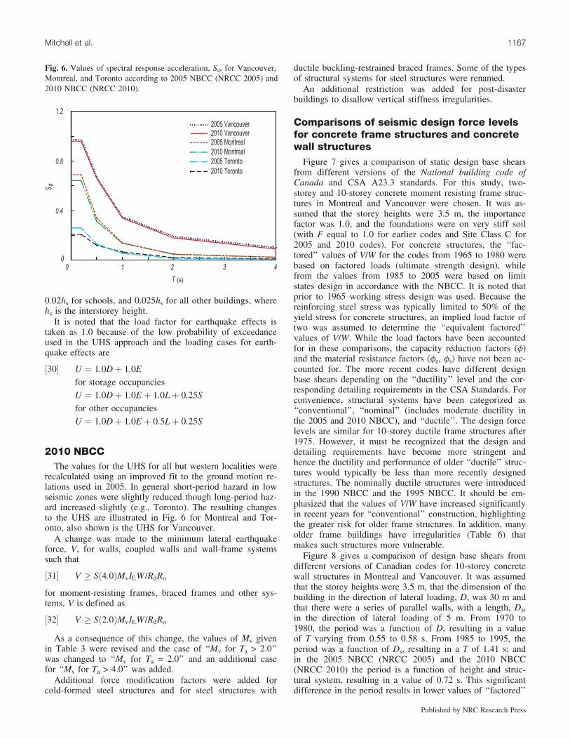
2010 NBCCThe values for the UHS for all but western localities were
recalculated using an improved fit to the ground motion re-lations used in 2005. In general short-period hazard in lowseismic zones were slightly reduced though long-period haz-ard increased slightly (e.g., Toronto). The resulting changesto the UHS are illustrated in Fig. 6 for Montreal and Tor-onto, also shown is the UHS for Vancouver.
A change was made to the minimum lateral earthquakeforce, V, for walls, coupled walls and wall-frame systemssuch that
½31� V � Sð4:0ÞMvIEW =RdRo
for moment-resisting frames, braced frames and other sys-tems, V is defined as
½32� V � Sð2:0ÞMvIEW =RdRo
As a consequence of this change, the values of Mv givenin Table 3 were revised and the case of ‘‘Mv for Ta > 2.0’’was changed to ‘‘Mv for Ta = 2.0’’ and an additional casefor ‘‘Mv for Ta > 4.0’’ was added.
Additional force modification factors were added forcold-formed steel structures and for steel structures with
ductile buckling-restrained braced frames. Some of the typesof structural systems for steel structures were renamed.
An additional restriction was added for post-disasterbuildings to disallow vertical stiffness irregularities.
Comparisons of seismic design force levelsfor concrete frame structures and concretewall structures
Figure 7 gives a comparison of static design base shearsfrom different versions of the National building code ofCanada and CSA A23.3 standards. For this study, two-storey and 10-storey concrete moment resisting frame struc-tures in Montreal and Vancouver were chosen. It was as-sumed that the storey heights were 3.5 m, the importancefactor was 1.0, and the foundations were on very stiff soil(with F equal to 1.0 for earlier codes and Site Class C for2005 and 2010 codes). For concrete structures, the ‘‘fac-tored’’ values of V/W for the codes from 1965 to 1980 werebased on factored loads (ultimate strength design), whilefrom the values from 1985 to 2005 were based on limitstates design in accordance with the NBCC. It is noted thatprior to 1965 working stress design was used. Because thereinforcing steel stress was typically limited to 50% of theyield stress for concrete structures, an implied load factor oftwo was assumed to determine the ‘‘equivalent factored’’values of V/W. While the load factors have been accountedfor in these comparisons, the capacity reduction factors (f)and the material resistance factors (fc, fs) have not been ac-counted for. The more recent codes have different designbase shears depending on the ‘‘ductility’’ level and the cor-responding detailing requirements in the CSA Standards. Forconvenience, structural systems have been categorized as‘‘conventional’’, ‘‘nominal’’ (includes moderate ductility inthe 2005 and 2010 NBCC), and ‘‘ductile’’. The design forcelevels are similar for 10-storey ductile frame structures after1975. However, it must be recognized that the design anddetailing requirements have become more stringent andhence the ductility and performance of older ‘‘ductile’’ struc-tures would typically be less than more recently designedstructures. The nominally ductile structures were introducedin the 1990 NBCC and the 1995 NBCC. It should be em-phasized that the values of V/W have increased significantlyin recent years for ‘‘conventional’’ construction, highlightingthe greater risk for older frame structures. In addition, manyolder frame buildings have irregularities (Table 6) thatmakes such structures more vulnerable.
Figure 8 gives a comparison of design base shears fromdifferent versions of Canadian codes for 10-storey concretewall structures in Montreal and Vancouver. It was assumedthat the storey heights were 3.5 m, that the dimension of thebuilding in the direction of lateral loading, D, was 30 m andthat there were a series of parallel walls, with a length, Ds,in the direction of lateral loading of 5 m. From 1970 to1980, the period was a function of D, resulting in a valueof T varying from 0.55 to 0.58 s. From 1985 to 1995, theperiod was a function of Ds, resulting in a T of 1.41 s; andin the 2005 NBCC (NRCC 2005) and the 2010 NBCC(NRCC 2010) the period is a function of height and struc-tural system, resulting in a value of 0.72 s. This significantdifference in the period results in lower values of ‘‘factored’’
Fig. 6. Values of spectral response acceleration, Sa, for Vancouver,Montreal, and Toronto according to 2005 NBCC (NRCC 2005) and2010 NBCC (NRCC 2010).
Mitchell et al. 1167
Published by NRC Research Press

base shear from 1985 to 1995, as shown in Fig. 8. In 1990and 1995, the R factors replaced the K factors for the differ-ent structural systems, a calibration factor (U of 0.6) was in-troduced and the load factor was reduced to 1.0. The
significant increase for the ‘‘factored’’ base shear in 2005 isdue mainly to the introduction of the UHS based on a prob-ability of exceedance of 2% in 50 years, which is partiallycompensated for by the force modification factors, by the
Table 6. Structural irregularities in 2005 NBCC.
Type Definition of irregularityVertical stiffness If lateral stiffness of SFRS in a storey is <70% of adjacent storey, or <80% of average of three
stories above or belowWeight If weight of any storey is >150% of adjacent storey (excluding roofs)Vertical geometry If horizontal dimension in a storey of the SFRS is >130% of adjacent storeyIn-plane discontinuity in SFRS If there is an in-plane offset of the SFRS or a reduction in lateral stiffness of resisting element in
the storey belowOut-of-plane offsets Discontinuities in the lateral force path, such as out-of-plane offsets of SFRS elementsWeak stories Storey shear strength less than that of storey aboveTorsional sensitivity If B = dmax/dave>1.7Non-orthogonal systems If the SFRS is not oriented along a set of orthogonal axes
Fig. 7. Comparisons of ‘‘factored’’ design base shears for concrete moment resisting frame structures in Montreal and Vancouver. Note thatvalues of V/W before 1965 were based on working stress design and hence were multiplied by 2 for comparison (a) two-storey frame(Montreal), (b) ten-storey frame (Montreal), (c) two-storey frame (Vancouver), and (d) ten-storey frame (Vancouver).
Fig. 8. Comparisons of ‘‘factored’’ design base shears for concrete wall structures in Montreal and Vancouver. Note that values of V/Wbefore 1965 were based on working stress design and hence were multiplied by two for comparison (a) ten-storey wall structure (Montreal)and (b) ten-storey wall structure (Vancouver).
1168 Can. J. Civ. Eng. Vol. 37, 2010
Published by NRC Research Press

steep drop of the spectral values in the low period range, bythe fact that the period was a function of the building heightrather than on Ds, and by the fact that the design base shearis no longer scaled to previous code values. Ghorbanirenaniet al. (2009) studied the nonlinear performance of walls de-signed and detailed in accordance with requirements of theNBCC between 1975 and 2005. They concluded that the wallsdesigned in accordance with the older codes (1975 to 1995)are likely to lack sufficient shear capacity over their height aswell as flexural strength above the plastic hinge region.
Conclusions
This paper provides a comparative study of the seismicdesign codes in Canada from the first code published in1941 to the present. The comparison of factored base shearsfor design of concrete structures provides a guide for design-ers faced with the difficult task of seismic evaluation of ex-isting structures. The key parameters that influence thesefactored base shears include seismicity, load factors, founda-tion conditions, determination of fundamental period, theseismic response factor, structural systems, and the corre-sponding design and detailing requirements. This compari-son was made possible by assuming a load factor of 2.0 forstructures that were designed using the working stress design(before 1965). This study illustrates the vulnerability of lowperiod structures designed with older codes. In evaluating anolder building, the engineer must be aware that majorchanges have taken place, not only with the design baseshears but also for the classifications of structural systemsthat depend on the design and detailing requirements. To ap-preciate the evolution of seismic design codes in Canada, itmust be recognized that there have been significant im-provements to the design and detailing requirements, in theCSA materials standards, that are consistently linked to theductility-based and the overstrength-based force modifica-tion factors.
AcknowledgementsThe authors gratefully acknowledge the financial support
provided by the Natural Sciences and Engineering ResearchCouncil of Canada (NSERC) for the Canadian Seismic Re-search Network (CSRN).
ReferencesACI. 1963. ACI standard building code requirements for reinforced
concrete – ACI 318–63. American Concrete Institute, Detroit,Michigan, 144 p.
Adams, J., and Atkinson, G. 2003. Development of seismic hazardmaps for the proposed 2005 edition of the National BuildingCode of Canada. Canadian Journal of Civil Engineering, 30(2):255–271. doi:10.1139/l02-070.
ATC. 1978. Tentative provisions for the development of seismicregulations for buildings. ATC 3–06, Applied Technology Coun-cil, National Bureau of Standards, Special Publication 510, U.S.Government Printing Office, Washington, D.C., 514 p.
Basham, P.W., Weichert, D.H., Anglin, F.M., and Berry, M.J.1985. New probabilistic strong seismic ground motion maps ofCanada. Bulletin of the Seismological Society of America, 75:563–595.
Blume, J.A., Newmark, N.M., and Corning, L.H. 1961. Design of
multistory reinforced concrete buildings for earthquake motions.Portland Cement Association, Skokie, IL, 318 p.
Bustamante, J.I., and Rosenblueth, E. 1960. Building code provi-sions on torsional oscillations. In Proceedings 2nd World Con-ference on Earthquake Engineering, Japan, 879–894.
Cornell, C.A. 1968. Engineering seismic risk analysis. Bulletin ofthe Seismological Society of America, 58: 1583–1606.
CSA. 1974. Steel structures for buildings – Limit states design –CSA S16.1–1974. Canadian Standards Association, Rexdale On-tario.
CSA. 1965. CSA Standard A23.3, Code for the design of concretestructures for buildings. Canadian Standards Association, Missis-sauga, ON.
CSA. 1973. CSA Standard A23.3, Code for the design of concretestructures for buildings. Canadian Standards Association, Missis-sauga, ON.
CSA. 1984. CSA Standard A23.3, Code for the design of concretestructures for buildings. Canadian Standards Association, Missis-sauga, ON.
DDF. 1966. Reglamento de Construcciones para el Distrito Federal,Departamento del Distrito Federal, Mexico City. [In Spanish.]
DeVall, R. 2003. Background information for some of the proposedearthquake design provisions for the 2005 edition of the Na-tional Building Code of Canada. Canadian Journal of Civil En-gineering, 30(2): 279–286. doi:10.1139/l02-048.
Finn, W.D.L., and Nichols, A.M. 1988. Seismic response of longperiod sites, lessons learned from the September 19, 1985 Mex-ican earthquake. Canadian Geotechnical Journal, 25: 128–137.
Finn, W.D.L., and Wightman, A. 2003. Ground motion amplifica-tion factors for the proposed 2005 edition of the National Build-ing Code of Canada. Canadian Journal of Civil Engineering,30(2): 272–278. doi:10.1139/l02-081.
Ghorbanirenani, I., Rallu, A., Tremblay, R., and Leger, P. 2009.Distribution of inelastic demand in slender R/C shear walls sub-jected to eastern North America ground motions. In Proceedingsof the ATC-SEI Conference on Improving the Seismic Perfor-mance of Existing Buildings and Other Structures, San Fran-cisco, Calif. pp. 1–13.
Hawkins, N.M., and Mitchell, D. 1977. Historical perspective,American Concrete Institute Special Publication, SP-53, Rein-forced Concrete Structures in Seismic Zones, American Con-crete Institute, pp. 1–23.
Heidebrecht, A.C. 2003. Overview of seismic provisions of the pro-posed 2005 edition of the National Building Code of Canada.Canadian Journal of Civil Engineering, 30(2): 241–254. doi:10.1139/l02-068.
Heidebrecht, A.C., Basham, P.W., Rainer, J.H., and Berry, M.J.1983. Engineering application of new probabilistic seismicground motions of Canada. Canadian Journal of Civil Engineer-ing, 10(4): 670–680. doi:10.1139/l83-096.
Hodgson, J.H. 1956. A seismic probability map for Canada. Re-search Paper No. 22, Division of Building Research, NationalResearch Council of Canada, Ottawa, Ont.
Humar, J., and Mahgoub, M.A. 2003. Determination of seismic de-sign forces by equivalent static load method. Canadian Journalof Civil Engineering, 30(2): 287–307. doi:10.1139/l02-067.
Humar, J., Yavari, S., and Saatcioglu, M. 2003. Design for forcesinduced by seismic torsion. Canadian Journal of Civil Engineer-ing, 30(2): 328–337. doi:10.1139/l02-029.
Milne, W.G., and Davenport, A.G. 1969. Distribution of earthquakerisk in Canada. Bulletin of the Seismological Society of Amer-ica, 59: 729–754.
Mitchell, D., Tremblay, R., Karacebeyli, E., Paultre, P., Saatcioglu,M., and Anderson, D.L. 2003. Seismic force modification fac-
Mitchell et al. 1169
Published by NRC Research Press

tors for the proposed 2005 edition of the National Building Codeof Canada. Canadian Journal of Civil Engineering, 30(2): 308–327. doi:10.1139/l02-111.
NEHRP. 1997. Recommended provisions for seismic regulationsfor new buildings and other structures. National Earthquake Ha-zard Reduction Program, Building Seismic Safety Council, Wa-shington, D.C.
Newmark, N.M., Blume, J.A., and Kapur, K.K. 1973. Seismic de-sign spectra for nuclear power plants. Journal of the Power Divi-sion, 99: 287–303.
NRCC. 1941. National Building Code of Canada, Associate Com-mittee on the National Building Code, National Research Coun-cil of Canada, Ottawa, ON.
NRCC. 1953. National Building Code of Canada, Associate Com-mittee on the National Building Code, National Research Coun-cil of Canada, Ottawa, ON.
NRCC. 1960. National Building Code of Canada, Associate Com-mittee on the National Building Code, National Research Coun-cil of Canada, Ottawa, ON.
NRCC. 1965. National Building Code of Canada, Associate Com-mittee on the National Building Code, National Research Coun-cil of Canada, Ottawa, ON.
NRCC. 1970. National Building Code of Canada, Associate Com-mittee on the National Building Code, National Research Coun-cil of Canada, Ottawa, ON.
NRCC. 1975. National Building Code of Canada, Associate Com-mittee on the National Building Code, National Research Coun-cil of Canada, Ottawa, ON.
NRCC. 1977. National Building Code of Canada, Associate Com-mittee on the National Building Code, National Research Coun-cil of Canada, Ottawa, ON.
NRCC. 1980. National Building Code of Canada, Associate Com-mittee on the National Building Code, National Research Coun-cil of Canada, Ottawa, ON.
NRCC. 1985. National Building Code of Canada, Associate Com-mittee on the National Building Code, National Research Coun-cil of Canada, Ottawa, ON.
NRCC. 1990. National Building Code of Canada, Associate Com-mittee on the National Building Code, National Research Coun-cil of Canada, Ottawa, ON.
NRCC. 1995. National Building Code of Canada, Associate Com-mittee on the National Building Code, National Research Coun-cil of Canada, Ottawa, ON.
NRCC. 2005.National Building Code of Canada, Associate Com-mittee on the National Building Code, National Research Coun-cil of Canada, Ottawa, ON.
NRCC. 2010. National Building Code of Canada, Associate Com-mittee on the National Building Code, National Research Coun-cil of Canada, Ottawa, ON.
Saatcioglu, M., and Humar, J. 2003. Dynamic analysis of buildingsfor earthquake-resistant design. Canadian Journal of Civil Engi-neering, 30(2): 338–359. doi:10.1139/l02-108.
SEAOC. 1959. Recommended lateral force requirements, SEAOCCode. Structural Engineers Association of California, Seismolo-gical committee, Sacramento, Calif.
Tso, W.K. 1992. Overview of seismic provision changes in Na-tional Building Code of Canada 1990. Canadian Journal of CivilEngineering, 19(3): 383–388. doi:10.1139/l92-046.
UBC. 1935. Uniform Building Code 1935. International Confer-ence of Building Officials (ICBO), Long Beach, California.
Uzumeri, S.M., Otani, S., and Collins, M.P. 1978. An overview ofCanadian code requirements for earthquake-resistant concretebuildings. Canadian Journal of Civil Engineering, 5(3): 427–441. doi:10.1139/l78-047.
Ward, H.S. 1966. Earthquake load provisions of the National build-ing code of Canada. Technical Paper No. 211, Division ofBuilding Research, National Research Council of Canada,Ottawa, ON.
1170 Can. J. Civ. Eng. Vol. 37, 2010
Published by NRC Research Press