evil mad scientist laboratories - amazon s3s3.amazonaws.com/evilmadscience/kitinstrux/peggy2.pdf ·...
TRANSCRIPT

PegGY 2.0: A Light Emitting Pegboard
Display Panel Kit
Making the World a Better Place,One Evil Mad Scientist at a Time
Evil Mad Scientist Laboratories
Support: http://www.evilmadscientist.com/forum/
Kit version 2.0
Manual v. 2.0A
An open-source hardware+software project
designed by
Distributed by
Evil Mad Science LLC

Intro + Tour Mounting holes: Top center : Hang it on a nail. Top 1/4 & 3/4: hang it on a string.
Corner mounting holes are 0.141” in diameter and are located 1/4x1/4” from each of the corners.
Transistors and resistors alongbottom edge of LED field.
CPU: ATmega168, atype off AVR microcontroller
LED Field: Peggy can fit up to 625 of your favorite LEDs in a big rectangular grid. Each LED location has room for a 10 mm LED, although smaller 5 mm (T-1 3/4, “standard size”) and 3 mm LEDs will work just as well.
Each LED location is numbered by itsrow and column location.
Bottom center and right:power management, optional button locations, and chips that peggy uses to address the LEDs.
1
Peggy is a tough and versatile LED “pegboard” display that can
drive a few or a lot of LEDs for
almost any purpose. Peggy can run on batteries or external
power. Peggy is programmable, open source and hackable.
Peggy can be the one to figure
out how to drive all your LEDs.
(US Quarter for scale)
Hi, I’m Peggy!
(Also: Programming interfaces, places to put switches, and more.)
Printed circuit board:Outline: 11.320” x 14.875”
(About 28.8 x 37.8 cm)

2
U4 and U5: STP16DP05 LED driver chips. The microcontroller uses these to control the rows of the display. (Over what’s called an “SPI” interface.)
Breadboard-style Prototype area!Clock area: Crystal oscillator
and two little helper capacitors. [Crystal location has three pins, just in case you wanted to use a 3-pin ceramic resonator instead.]
USB-TTL interfaceIf you have a USB-TTL cable, you can use this port to program or communicate with Peggy, much like you would with an Arduino.
Buttons!Reset and “OFF/SELECT” buttons are standard. “Off” is only a software mode-- only mostly off. To save power, use the switch instead.
U1: ATmega168 microcontroller, in a socket. Extra, labeled holes are provided on all of the pins for your hacking pleasure.
If reprogramming the display, you may want to add an “Any” key for activating your own purposes.
Detailed tour: Lower left corner of board
AVR-ISP interface6-pin connector can hook up to your AVR in-system programmer, if ya got one.

3
J2, S3: External powerPower jack + switch locations.
The switch chooses the power source: Internal (battery) or
external (from the power jack.)Battery power: On to the rightExternal power: On to the left.
Detailed Tour: Lower right end of board
Row of transistors
Row of resistors
Battery box goes here
U2 and U3: CD74HC154’s“Demultiplexer” helper chips that the microcontroller uses to drive the columns of the display.
Extra locationsfor optional buttons
Not much for these to do on a static LED display, but maybe, if you were
reprogramming the display, these could be made to do something interesting.

What do you make of this?
Hardware hackers may want to flip through the schematics (pages 13-15) before going further to see if inspiration strikes. A wide variety of hacks, mods, and improvements are possible; the circuitry was designed with hacking in mind. A prototype area is provided to add extra components and extra access holes have been added to allow direct access to the microcontroller pins.
Our standard assembly instructions, beginning on the next page, will produce a static “pegboard” display, that will light up LEDs in whichever locations you choose to install them, with near-uniform current applied to each LED.
They will be driven in an energy-efficient multiplexed arrangement, which makes an easy LED display when you put your LEDs in just the locations where you want them. Adding additional functionality, for example, turning on specific LEDs or making simple animation or a true interactive display, can be done by reprogramming the display through one of the two provided interfaces.
4
If you do wish to reprogram the display... two different types of external interface are supported.
A 6-pin ISP interface (J1) lets you program the board using an in-system programmer, for example the USBtinyISP by Adafruit Industries. This interface is supported through the AVR-GCC toolchain
As a second option, the display can be programmed through the Arduino software environment (www.arduino.cc), using an FTDI USB-TTL serial interface cable, which attaches at location J3.
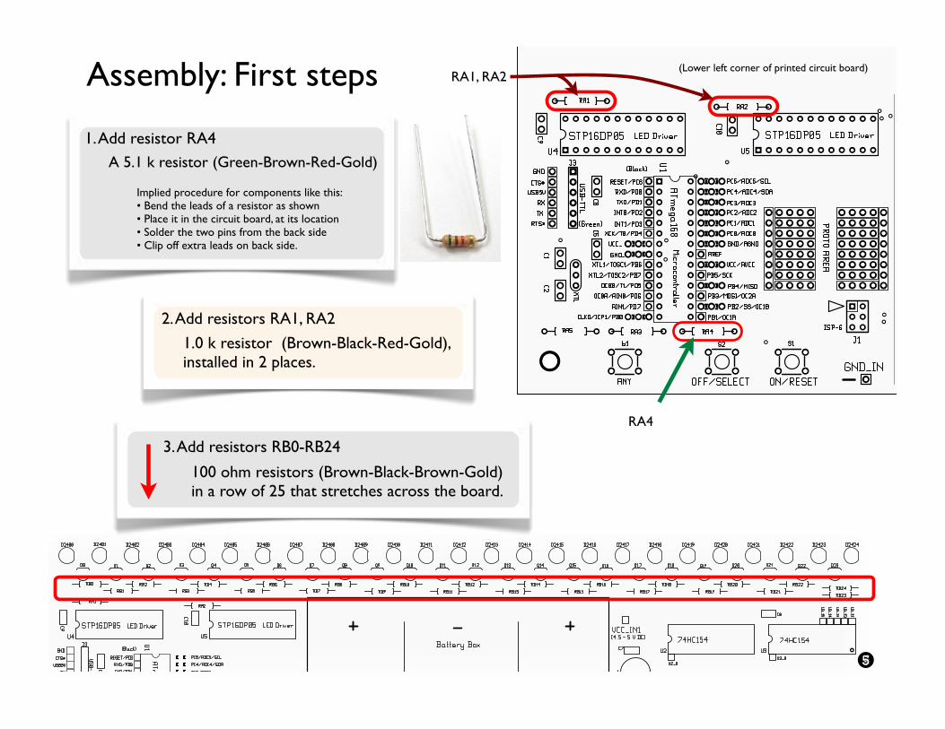
Assembly: First steps
1. Add resistor RA4
A 5.1 k resistor (Green-Brown-Red-Gold)
Implied procedure for components like this:• Bend the leads of a resistor as shown• Place it in the circuit board, at its location• Solder the two pins from the back side• Clip off extra leads on back side.
2. Add resistors RA1, RA2
1.0 k resistor (Brown-Black-Red-Gold),installed in 2 places.
(Lower left corner of printed circuit board)
5
RA4
RA1, RA2
3. Add resistors RB0-RB24
100 ohm resistors (Brown-Black-Brown-Gold) in a row of 25 that stretches across the board.

Assembly: Adding the sockets
24-pin DIP sockets, installed in four locations
Follow the same procedure as in Step 5.
6
5. Install sockets for chips U2, U3, U4, and U5.
U2 U3U4 U5
(Lower left corner of printed circuit board)
A 28-pin DIP socket (the long chip socket)
Orientation matters: Match the “half-moon” shape at one end of the socket to the one drawn on the circuit board.
Tight fit: These sockets snap flush into place, so they stay put when you turn the board upside down to solder them. Make sure that the orientation is correct, that every pin is in the right hole and then press uniformly and firmly to seat it.
Solder every pin of the socket in place.
4. Install socket for chip U1.

Assembly: Next steps
6. Add crystal oscillator XTL
(Lower left corner of printed circuit board)
7
S1 & S2
8. Add tactile button switches S1 and S2Match the parts to the drawing on the circuit board.
Orientation: pins stick out on left and right sides, not top and bottom.
Solder all four pins of each switch.
7. Install capacitors C1 & C2
18 pF ceramic caps, 2 places. (Orientation: Either way.) [The labels on these tiny capacitors are not useful; these are the two little caps attached together.]
A shiny steel can. The two pins go in the outer two holes of location XTL; ignore the middle hole.
(Orientation: Either way.)
C1 & C2
6-pin SIL (1x6) header (J3)
6-pin DIL (2x3) header (J1)
9. (Optional) Add headers J1 and/or J3
These connectors are only needed if you plan to reprogram your Peggy with an external interface.
J1: a 6-pin DIL header for use with an AVR-ISP programmerJ3: a 6-pin SIL header for use with a USB-TTL cable
Tight fit: These headers sit snugly in the holes so that they stay in place when you turn the board upside down to solder them. Press firmly to seat them.
J3
J1XTL

Q0-Q24Assembly: Transistors and more capacitors
10. Add transistors Q0-Q24. 2N5401 transistors, installed in 25 places.
Flat face
Orientation matters. Match the flat face of the transistors to the drawing on the board.
11. Install capacitor C3
1000 uF electrolytic cap
Orientation matters. The NEGATIVE side of thecapacitor is marked with a broad white stripe.Solder it with this negative side towards “-” on the circuit board.
+-
12. Install capacitors C4 through C10
0.1 uF ceramic caps installed in 7 locations
(Orientation: Either way.) Again, the labels are tiny. If your eyes are very good, you might be able to make out the legend “104.”
8
C3
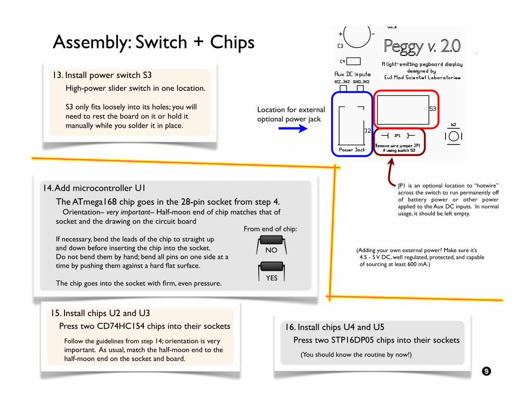
Assembly: Switch + Chips
13. Install power switch S3
High-power slider switch in one location.
S3 only fits loosely into its holes; you will need to rest the board on it or hold it manually while you solder it in place.
(Adding your own external power? Make sure it’s 4.5 - 5 V DC, well regulated, protected, and capable of sourcing at least 600 mA.)
9
Location for external optional power jack
JP1 is an optional location to “hotwire” across the switch to run permanently off of battery power or other power applied to the Aux DC inputs. In normal usage, it should be left empty.
The ATmega168 chip goes in the 28-pin socket from step 4. Orientation-- very important-- Half-moon end of chip matches that of socket and the drawing on the circuit board
If necessary, bend the leads of the chip to straight upand down before inserting the chip into the socket.Do not bend them by hand; bend all pins on one side at atime by pushing them against a hard flat surface.
The chip goes into the socket with firm, even pressure.
14. Add microcontroller U1
From end of chip:
NO
YES
16. Install chips U4 and U5
Press two STP16DP05 chips into their sockets
15. Install chips U2 and U3
Press two CD74HC154 chips into their sockets
Follow the guidelines from step 14; orientation is very important. As usual, match the half-moon end to the half-moon end on the socket and board.
(You should know the routine by now!)
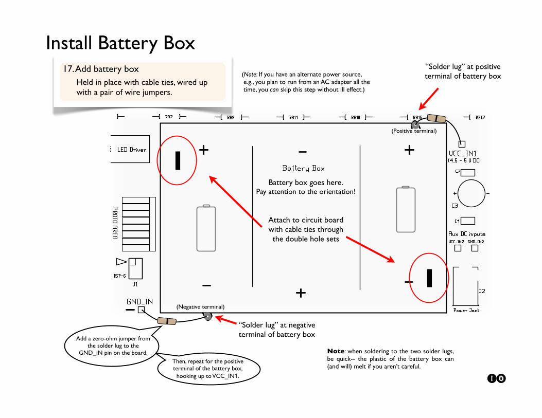
Battery box goes here.Pay attention to the orientation!
Attach to circuit boardwith cable ties through the double hole sets
(Positive terminal)
Then, repeat for the positive terminal of the battery box,
hooking up to VCC_IN1.
Add a zero-ohm jumper from the solder lug to the
GND_IN pin on the board.
“Solder lug” at negative terminal of battery box
Install Battery Box“Solder lug” at positive terminal of battery box
17. Add battery box
Held in place with cable ties, wired up with a pair of wire jumpers.
Note: when soldering to the two solder lugs, be quick-- the plastic of the battery box can (and will) melt if you aren’t careful.
10
(Note: If you have an alternate power source, e.g., you plan to run from an AC adapter all the time, you can skip this step without ill effect.)
(Negative terminal)

Assembly: Adding LEDs
The board accommodates up to 625 LEDs in standard sizes up to 10 mm. 3 mm, 5 mm, and 8 mm LEDs will work just fine. Put them where you like, or everywhere.
For standard types of LEDs, the long lead goes in the square hole (the one on the left), and the flat face of the LED package matches the drawing on the circuit board.
For reference, each LED location is labeled DXXYY, where XX is the row number and YY is the column number. If you do not fill all the holes and wish to blacken the unused labels, a black permanent marker works well.
18. Add LEDs to the LED field.
Flat face
Long lead
Long leadinto
square hole
11
LED Field
Bend out Bend down
1. 2. 3.
Where the grid really won’t do, you can put LEDs between grid locations. Which ever way you do it, the side of each LED with long lead still goes to square hole. Side with flat still goes to round hole.
This procedure is recommended mainly for staticsigns and LED displays; putting LEDs between grid locations can make programming those grid locations more complicated.
Alternative build idea: put all the LEDs on the back side of the circuit board for truly bare background. In this scheme, the long lead still goes in the square hole.

Wrapping it up!
Attach one rubber foot in each corner on the back side of the circuit board, and a couple closer to the middle, to protect against bending when you press buttons-- make sure that the circuit board lies flat on these bumpers, not on wire leads.
The feet will help to avoid accidental short circuits, as well as protect your wall if you hang it up by a hook or string.
Last step: Add the rubber feet
The hardware and software designs used in this project are being released under an open-source license. For more information, please see:
http://www.evilmadscientist.com/article.php/peggy2
Example firmware is available for download, and we’d love to see what you can do with it!
An open-source project
If you have interesting pictures or video of things built using this kit or the hardware or software designs, we’d love to see them in the Evil Mad Science Auxiliary: http://www.flickr.com/groups/evilmadscience/
Got pictures?
12
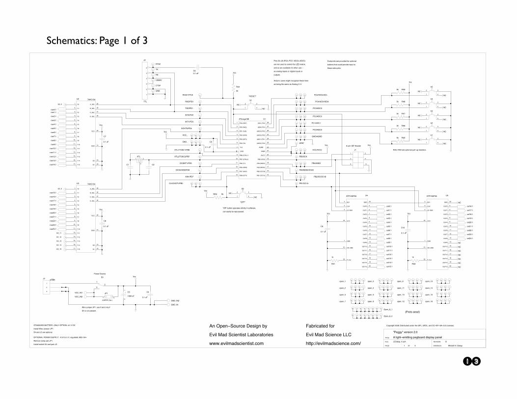
Schematics: Page 1 of 3
13
!"#$$%!&'#()*+,&-./
0&1*$23!#4*33*,$&5#$6+7(8&8*)517%&57,#1
9 :
;<=8*)5>?.)@2 A
B*,8#11&C.&D)E7%
FG;<H I<JGKGDLH
=I0BL&AMH&"0N< DF
OGO;<
-
9
:
K:
-
9
:
P-QJ*,
JRR>GL9
J@@
NL=>GL-
"+S#(&K+T(@#
0,&D5#,!K+T(@#&=#)*$,&6%
<'*1&U78&K@*#,3*)3&;76+(73+(*#)
SSS.#'*1478)@*#,3*)3.@+4
F76(*@73#8&V+(
<'*1&U78&K@*#,@#&;;R
2335HWW#'*1478)@*#,@#.@+4W
NL=>GL
JRR>GL-
9I<K<OW"RX
I0: YE
J@@
!DFF!
I0Z
YE
J@@
!I<K<O!
9 Z
- :
K9
9 Z
- :
K-
9-
9///&TF
R:
(+S-ZH9
-9
P[U"<I&\D53.]
P"9
(+S^H9
(+S9YH9
(+S9ZH9
(+S9:H9
(+S9-H9
(+S9/H9
(+S99H9
(+S_H9
(+S`H9
(+S/H9
(+S9H9
(+S-H9
(+S:H9
(+SZH9
(+SYH9
(+SXH9
(+S9XH9
(+S9^H9
(+S9`H9
(+S9_H9
(+S-/H9
(+S-9H9
(+S--H9
(+S-:H9
D"OGDL0;&"DB<I&K["";MH&&Z.YJ&3+&Y&Ja&(#$T173#8a&X//&40Q
I#4+'#&\),*5&+T3]&P"9.
G,)3711&)S*3@2&KZ&7,8&b7@E&P-.
B*(#&bT45#(&P"9H&T)#&*V&7,8&+,1%&*V
KZ&*)&,+3&5(#)#,3.
9 "RX&\IKO]
- "=/&\Ic=]
: "=9&\Oc=]
Z "=-&\GLO/]
Y "=:&\GLO9]
X "=Z&\O/]
_ "AX&\?O0;9]
9/ "A^&\?O0;-]
99 "=Y&\O9]
9- "=X&\0GL/]
9: "=^&\0GL9]
9Z "A/&\GR"9] 9Y"A9&\DR90]
9X"A-&\DR9A]
9^"A:&\UDKG]
9`"AZ&\UGKD]
9_"AY&\KRd]
-/0JRR
-90I<F
-:\0=R/]&"R/
-Z\0=R9]&"R9
-Y\0=R-]&"R-
-X\0=R:]&"R:
-^\K=0]&"RZ
-`\KR;]&"RY
J@@^
` NL=
--0NL=
[90O4#$79X`
9 -
: Z
Y X
P9
: - 9JRR>
: - 9NL=>
: - 9R;dDWGR"9W"A/
:-9 "RYW0=RYWKR;
:-9 "RZW0=RZWK=0
:-9 "R:W0=R:
:-9 "R/W0=R/
:-9 "R9W0=R9
:-9 "R-W0=R-
:-9 NL=W0NL=
:-9 JRRW0JRR
:-9 "AZWUGKD
:-9 "A-WKKWDR9A
X!5*,&GK"&C#78#(
R+5%(*$23&-//`e&=*)3(*6T3#8&T,8#(&32#&N";a&NF=;a&7,8&RR!AM!K0!:./&;*@#,)#).
9?O;9WODKR9W"AX
9?O;-WODKR-W"A^
J@@
RZ
/.9&TF
R9 R-
9
-
:
?O;
RY
/.9&TF
RX
/.9&TF
KO0L=0I=&A0OO<IM!DL;M&D"OGDLH&Z.Y&J&=R
G,)3711&B*(#&PT45#(&P"9.
KZ&7,8&P-&7(#&+53*+,71.
9
-
:
Z
Y
X
P:
OO;
J@@
9 0I<F
9 [KAYJ
9 IOKf
9 O?
9 I?
9 ROKf
9 NL=
9 "AYWKRd
J@@
9 "A:WUDKGWDR-0
J@@
R^
/.9&TF
J@@
R`
/.9&TF
9[->/
9[:>/
9[:>99
9[:>9-
9[:>9:
9[:>9Z
9[:>9Y
9 M/
- M9
: M-
Z M:
Y MZ
X MY
^ MX
` M^
_ M`
9/ M_
99 M9/
-:0>K<;
--A>K<;
-9R>K<;
-/=>K<;
9_N-
9`N99^ M9Y
9X M9Z
9Y M9:
9Z M9-
9: M99
^ZCR9YZ
-ZJRR
9-NL=
[:
9 M/
- M9
: M-
Z M:
Y MZ
X MY
^ MX
` M^
_ M`
9/ M_
99 M9/
-:0>K<;
--A>K<;
-9R>K<;
-/=>K<;
9_N-
9`N99^ M9Y
9X M9Z
9Y M9:
9Z M9-
9: M99
^ZCR9YZ
-ZJRR
9-NL=
[-
9I?=W"=/
9O?=W"=9
9GLO/W"=-
9GLO9W"=:
9?RdWO/W"=Z
90GL9W"=^
9DR/0W0GL/W"=X
9DR/AWO9W"=Y
J@@
R_
/.9&TF
YD[O/
XD[O9
^D[O-
`D[O:
_D[OZ
9/D[OY
99D[OX
9-D[O^
9:D[O`
9ZD[O_
9YD[O9/
- K=G
: R;d
Z ;<!=U9
-/D[O9Y
9_D[O9Z
9`D[O9:
9^D[O9-
9XD[O99
KO"9X="/Y
-Z JRR
9 NL=
--K=D
-: I><c3
-9 D<!=U-
[Z
I09
9E
J@@
R9/
/.9&TF
YD[O/
XD[O9
^D[O-
`D[O:
_D[OZ
9/D[OY
99D[OX
9-D[O^
9:D[O`
9ZD[O_
9YD[O9/
- K=G
: R;d
Z ;<!=U9
-/D[O9Y
9_D[O9Z
9`D[O9:
9^D[O9-
9XD[O99
KO"9X="/Y
-Z JRR
9 NL=
--K=D
-: I><c3
-9 D<!=U-
[Y
I0-
9E
9 "A9WDR90
@+1/H9
@+19H9
@+1:H9
@+1^H9
@+1XH9
@+1YH9
@+1ZH9
@+19YH9
@+19ZH9
@+19:H9
@+19-H9
@+1`H9
@+19/H9
@+199H9
@+1--H9
@+1-9H9
@+1-/H9
@+19XH9
@+19`H9
@+19^H9
@+19_H9
LR
LR
LR
LR
LR
LR
LR
"*,)&-:!-`&\"R/!"RY&&0=R/!0=RY]&
7(#&,+3&T)#8&3+&@+,3(+1&32#&;<=&473(*ca&
7,8&)+&7(#&7'7*1761#&V+(&+32#(&T)#!!&
7)&7,71+$&*,5T3)&+(&8*$*371&*,5T3)&+(
+T35T3).
@+1-ZH9
@+1-:H9
LR
@+1-H9
@+1_H9
J@@
9 Z
- :
69
LR
LR
LR
LR
LR
LRI0YYE
9 Z
- :
6-
LR
LRI0XYE
9 Z
- :
6:
LR
LRI0^YE
9 Z
- :
6Z
LR
LRI0`YE
9 Z
- :
6Y
LR
LRI0_YE
I0Y!I0_&7(#&+53*+,71&5T11!T5&(#)*)3+().
0(8T*,+&T)#()&4*$23&(#@+$,*g#&32#)#&1*,#)
7)&6#*,$&32#&)74#&7)&0,71+$&/!Y
!DVV!&6T33+,&+5#(73#)&)3(*@31%&*,&)+V3S7(#a
@7,)*1%&6#&(#5T(5+)#8.
F++35(*,3)&7(#&5(+'*8#8&V+(&+53*+,71
6T33+,)&3273&@+T18&5(+'*8#&*,5T3&3+
32#)#&#c3(7&5*,).&&
: -Z 9YX^`
D5#,>`>9
: -Z 9YX^`
D5#,>`>-
: -Z 9
+5#,>9
: -Z 9
+5#,>-
: -Z 9
+5#,>Y
: -Z 9
+5#,>^
: -Z 9
+5#,>:
: -Z 9
+5#,>Z
: -Z 9
+5#,>X
: -Z 9
+5#,>`
: -Z 9
+5#,>_
: -Z 9
+5#,>99
: -Z 9
+5#,>9/
: -Z 9
+5#,>9-
: -Z 9
+5#,>9:
: -Z 9
+5#,>9Z
: -Z 9
+5#,>9Y
: -Z 9
+5#,>9X
\"(+3+&7(#7h]
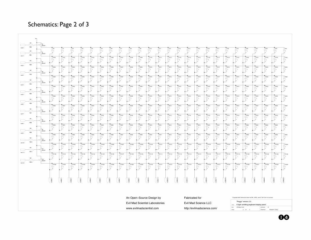
Schematics: Page 2 of 3
14
! "
#$%&'()*+,(-.
/'0&12234,35(678
9:#$; <$=:>:5?;
%<@/?3AB;3C@D$ 59
E:E#$
<AF
GFF
G!
%F
G!
%G
G!
%GFF
G!
%GFG
G!
%!FF
G!
%!FG
G!
%"FF
G!
%"FG
G!
%HFF
G!
%HFG
G!
%IFF
G!
%IFG
G!
%JFF
G!
%JFG
G!
%KFF
G!
%KFG
G!
%LFF
G!
%LFG
G!
%MFF
G!
%MFG
G!
%GFFG
G!
%GGFF
G!
%GGFG
G!
%GFFF
G!
%!
G!
%GF!
G!
%!F!
G!
%"F!
G!
%HF!
G!
%IF!
G!
%JF!
G!
%KF!
G!
%LF!
G!
%MF!
G!
%GFF!
G!
%GGF!
G!
%"
G!
%GF"
G!
%!F"
G!
%"F"
G!
%HF"
G!
%IF"
G!
%JF"
G!
%KF"
G!
%LF"
G!
%MF"
G!
%GFF"
G!
%GGF"
G!
%H
G!
%GFH
G!
%!FH
G!
%"FH
G!
%HFH
G!
%IFH
G!
%JFH
G!
%KFH
G!
%LFH
G!
%MFH
G!
%GFFH
G!
%GGFH
G!
%GFJ
G!
%!FJ
G!
%"FJ
G!
%HFJ
G!
%IFJ
G!
%JFJ
G!
%KFJ
G!
%LFJ
G!
%MFJ
G!
%GFFJ
G!
%GGFJ
G!
%GFK
G!
%!FK
G!
%"FK
G!
%HFK
G!
%IFK
G!
%JFK
G!
%KFK
G!
%LFK
G!
%MFK
G!
%GFFK
G!
%GGFK
G!
%GFL
G!
%!FL
G!
%"FL
G!
%HFL
G!
%IFL
G!
%JFL
G!
%KFL
G!
%LFL
G!
%MFL
G!
%GFFL
G!
%GGFL
G!
%GFM
G!
%!FM
G!
%"FM
G!
%HFM
G!
%JFM
G!
%KFM
G!
%LFM
G!
%MFM
G!
%GFFM
G!
%GGFM
G!
%GGF
G!
%!GF
G!
%"GF
G!
%HGF
G!
%JGF
G!
%KGF
G!
%LGF
G!
%MGF
G!
%GFGF
G!
%GGGF
G!
%GGG
G!
%!GG
G!
%"GG
G!
%HGG
G!
%JGG
G!
%KGG
G!
%LGG
G!
%MGG
G!
%GFGG
G!
%GGGG
G!
%GFI
G!
%!FI
G!
%"FI
G!
%HFI
G!
%IFI
G!
%JFI
G!
%KFI
G!
%LFI
G!
%MFI
G!
%GFFI
G!
%GGFI
G!
%G!
G!
%GG!
G!
%!G!
G!
%"G!
G!
%HG!
G!
%JG!
G!
%KG!
G!
%LG!
G!
%MG!
G!
%GFG!
G!
%GGG!
G!
%G"
G!
%GG"
G!
%!G"
G!
%"G"
G!
%HG"
G!
%JG"
G!
%KG"
G!
%LG"
G!
%MG"
G!
%GFG"
G!
%GGG"
G!
%GH
G!
%GGH
G!
%!GH
G!
%"GH
G!
%HGH
G!
%JGH
G!
%KGH
G!
%LGH
G!
%MGH
G!
%GFGH
G!
%GGGH
G!
%GGJ
G!
%!GJ
G!
%"GJ
G!
%JGJ
G!
%KGJ
G!
%LGJ
G!
%MGJ
G!
%GFGJ
G!
%GGGJ
G!
%GGK
G!
%!GK
G!
%"GK
G!
%HGK
G!
%JGK
G!
%KGK
G!
%LGK
G!
%MGK
G!
%GFGK
G!
%GGGK
G!
%GGL
G!
%!GL
G!
%"GL
G!
%HGL
G!
%JGL
G!
%KGL
G!
%LGL
G!
%MGL
G!
%GFGL
G!
%GGGL
G!
%GGM
G!
%!GM
G!
%"GM
G!
%HGM
G!
%JGM
G!
%KGM
G!
%LGM
G!
%MGM
G!
%GFGM
G!
%GGGM
G!
%G!F
G!
%!!F
G!
%"!F
G!
%H!F
G!
%J!F
G!
%K!F
G!
%L!F
G!
%M!F
G!
%GF!F
G!
%GG!F
G!
%G!G
G!
%!!G
G!
%"!G
G!
%H!G
G!
%J!G
G!
%K!G
G!
%L!G
G!
%M!G
G!
%GF!G
G!
%GG!G
G!
%GGI
G!
%!GI
G!
%"GI
G!
%JGI
G!
%KGI
G!
%LGI
G!
%MGI
G!
%GFGI
G!
%GGGI
G!
%!!
G!
%G!!
G!
%!!!
G!
%"!!
G!
%H!!
G!
%J!!
G!
%K!!
G!
%L!!
G!
%M!!
G!
%GF!!
G!
%GG!!
G!
%!"
G!
%G!"
G!
%!!"
G!
%"!"
G!
%H!"
G!
%J!"
G!
%K!"
G!
%L!"
G!
%M!"
G!
%GF!"
G!
%GG!"
G!
%!H
G!
%G!H
G!
%!!H
G!
%"!H
G!
%H!H
G!
%J!H
G!
%K!H
G!
%L!H
G!
%M!H
G!
%GF!H
G!
%GG!H
G!
%!G
G!
%GI
G!
%GJ
G!
%GK
G!
%GL
G!
%GM
G!
%!F
G!
%IG!
G!
%IG"
G!
%IGH
G!
%IGI
G!
%IGJ
G!
%IGK
G!
%IGL
G!
%IFM
G!
%IGF
G!
%IGG
G!
%IGM
G!
%I!F
G!
%I!G
G!
%I!!
G!
%I!"
G!
%I!H
G!
%GG
G!
%GF
G!
%M
G!
%L
G!
%K
G!
%J
G!
%INOPF;G
QO)8N'R.S3!FFLT3%'(SN'UVS1&3V0&1N3S.13DC#W3D9%#W370&3QQ!AB!>@!",F3#'-10(1(,
XC1RR8X3Y1N('O03!,F
@32'R.S!1Z'SS'0R3)1RUO7N&3&'()2783)7012
97UN'-7S1&3[ON
$Y'23\7&3>-'10-13##Q
.SS);]]1Y'2Z7&(-'10-1,-OZ]
@035)10!>OVN-13%1('R03U8
$Y'23\7&3>-'10S'(S3#7UON7SON'1(
PPP,1Y'2Z7&(-'10S'(S,-OZA
"
!
G
^F
!?IHFG
=--
<AG
GFF
<A"
GFF
<A!
GFF
<AK
GFF
<AJ
GFF
<AI
GFF
<AH
GFF
<AGG
GFF
<AGF
GFF
<AM
GFF
<AL
GFF
NOPG;G
NOP!;G
NOP";G
NOPJ;G
NOPK;G
NOPI;G
NOPH;G
NOPGF;G
NOPGG;G
NOPM;G
NOPL;G
G!
%HGI
G!
%HGJ
"
!
G
^G
!?IHFG
"
!
G
^"
!?IHFG
"
!
G
^!
!?IHFG
QO2\'&F;G
QO2\'&G;G
QO2\'&";G
QO2\'&!;G
QO2\'&H;G
QO2\'&I;G
QO2\'&K;G
QO2\'&J;G
QO2\'&L;G
QO2\'&M;G
QO2\'&GG;G
QO2\'&GF;G
QO2\'&G!;G
QO2\'&G";G
QO2\'&GI;G
QO2\'&GH;G
QO2\'&GJ;G
QO2\'&GK;G
QO2\'&GM;G
QO2\'&GL;G
QO2\'&!F;G
QO2\'&!G;G
QO2\'&!";G
QO2\'&!!;G
QO2\'&!H;G
<AG!
GFF
NOPG!;G G!
%G!FF
G!
%G!FG
G!
%G!F!
G!
%G!F"
G!
%G!FH
G!
%G!G!
G!
%G!G"
G!
%G!GH
G!
%G!!!
G!
%G!!"
G!
%G!!H
G!
%G!GG
G!
%G!FI
G!
%G!FJ
G!
%G!FK
G!
%G!FL
G!
%G!FM
G!
%G!GF
G!
%G!!G
G!
%G!GI
G!
%G!GJ
G!
%G!GK
G!
%G!GL
G!
%G!GM
G!
%G!!F
"
!
G
^J
!?IHFG
"
!
G
^I
!?IHFG
"
!
G
^H
!?IHFG
"
!
G
^GF
!?IHFG
"
!
G
^M
!?IHFG
"
!
G
^L
!?IHFG
"
!
G
^GG
!?IHFG
"
!
G
^K
!?IHFG
"
!
G
^G!
!?IHFG

Schematics: Page 3 of 3
15
! !
"#$%&'()*+',-
.&/%01123+24'567
89"#: ;#<9=94>:
$;?.>2@A:2B?C# 48
D9D"#
EF
$EGHH
EF
$EGHE
EF
$EIHH
EF
$EIHE
EF
$EJHH
EF
$EJHE
EF
$EKHH
EF
$EKHE
EF
$ELHH
EF
$ELHE
EF
$FHHH
EF
$FHHE
EF
$FEHH
EF
$FEHE
EF
$FFHH
EF
$FFHE
EF
$F!HE
EF
$FMHH
EF
$FMHE
EF
$F!HH
EF
$EGHF
EF
$EIHF
EF
$EJHF
EF
$EKHF
EF
$ELHF
EF
$FHHF
EF
$FEHF
EF
$FFHF
EF
$F!HF
EF
$FMHF
EF
$EGH!
EF
$EIH!
EF
$EJH!
EF
$EKH!
EF
$ELH!
EF
$FHH!
EF
$FEH!
EF
$FFH!
EF
$F!H!
EF
$FMH!
EF
$EGHM
EF
$EIHM
EF
$EJHM
EF
$EKHM
EF
$ELHM
EF
$FHHM
EF
$FEHM
EF
$FFHM
EF
$F!HM
EF
$FMHM
EF
$EGHI
EF
$EIHI
EF
$EJHI
EF
$EKHI
EF
$ELHI
EF
$FHHI
EF
$FEHI
EF
$FFHI
EF
$F!HI
EF
$EGHJ
EF
$EIHJ
EF
$EJHJ
EF
$EKHJ
EF
$ELHJ
EF
$FHHJ
EF
$FEHJ
EF
$FFHJ
EF
$F!HJ
EF
$EGHK
EF
$EIHK
EF
$EJHK
EF
$EKHK
EF
$ELHK
EF
$FHHK
EF
$FEHK
EF
$FFHK
EF
$F!HK
EF
$EGHL
EF
$EIHL
EF
$EJHL
EF
$ELHL
EF
$FHHL
EF
$FEHL
EF
$FFHL
EF
$F!HL
EF
$EGEH
EF
$EIEH
EF
$EJEH
EF
$ELEH
EF
$FHEH
EF
$FEEH
EF
$FFEH
EF
$F!EH
EF
$EGEE
EF
$EIEE
EF
$EJEE
EF
$ELEE
EF
$FHEE
EF
$FEEE
EF
$FFEE
EF
$F!EE
EF
$EGHG
EF
$EIHG
EF
$EJHG
EF
$EKHG
EF
$ELHG
EF
$FHHG
EF
$FEHG
EF
$FFHG
EF
$F!HG
EF
$EGEF
EF
$EIEF
EF
$EJEF
EF
$ELEF
EF
$FHEF
EF
$FEEF
EF
$FFEF
EF
$F!EF
EF
$FMEF
EF
$EGE!
EF
$EIE!
EF
$EJE!
EF
$ELE!
EF
$FHE!
EF
$FEE!
EF
$FFE!
EF
$F!E!
EF
$FME!
EF
$EGEM
EF
$EIEM
EF
$EJEM
EF
$ELEM
EF
$FHEM
EF
$FEEM
EF
$FFEM
EF
$F!EM
EF
$FMEM
EF
$EGEI
EF
$EIEI
EF
$EJEI
EF
$ELEI
EF
$FHEI
EF
$FEEI
EF
$FFEI
EF
$F!EI
EF
$EGEJ
EF
$EIEJ
EF
$EJEJ
EF
$ELEJ
EF
$FHEJ
EF
$FEEJ
EF
$FFEJ
EF
$F!EJ
EF
$EGEK
EF
$EIEK
EF
$EJEK
EF
$ELEK
EF
$FHEK
EF
$FEEK
EF
$FFEK
EF
$F!EK
EF
$EGEL
EF
$EIEL
EF
$EJEL
EF
$ELEL
EF
$FHEL
EF
$FEEL
EF
$FFEL
EF
$F!EL
EF
$EGFH
EF
$EIFH
EF
$EJFH
EF
$ELFH
EF
$FHFH
EF
$FEFH
EF
$FFFH
EF
$F!FH
EF
$EGFE
EF
$EIFE
EF
$EJFE
EF
$ELFE
EF
$FHFE
EF
$FEFE
EF
$FFFE
EF
$F!FE
EF
$EGEG
EF
$EIEG
EF
$EJEG
EF
$ELEG
EF
$FHEG
EF
$FEEG
EF
$FFEG
EF
$F!EG
EF
$EGFF
EF
$EIFF
EF
$EJFF
EF
$ELFF
EF
$FHFF
EF
$FEFF
EF
$FFFF
EF
$F!FF
EF
$FMFF
EF
$EGF!
EF
$EIF!
EF
$EJF!
EF
$ELF!
EF
$FHF!
EF
$FEF!
EF
$FFF!
EF
$F!F!
EF
$FMF!
EF
$EGFM
EF
$EIFM
EF
$EJFM
EF
$ELFM
EF
$FHFM
EF
$FEFM
EF
$FFFM
EF
$F!FM
EF
$FMFM
EF
$EKEF
EF
$EKE!
EF
$EKEM
EF
$EKEG
EF
$EKEI
EF
$EKEJ
EF
$EKEK
EF
$EKHL
EF
$EKEH
EF
$EKEE
EF
$EKEL
EF
$EKFH
EF
$EKFE
EF
$EKFF
EF
$EKF!
EF
$EKFM
EF
$FMEE
EF
$FMEH
EF
$FMHL
EF
$FMHK
EF
$FMHJ
EF
$FMHI
EF
$FMHG
EF
$FMFE
EF
$FMFH
EF
$FMEL
EF
$FMEK
EF
$FMEJ
EF
$FMEI
EF
$FMEG
NO(7P&Q-R2FHHKS2$&'RP&TUR0%2U/%0P2R-02CB"V2C8$"V26/%2NN!@A!=?!!+H2"&,0/'0'+
WB0QQ7W2X0P'&O/2F+H
?21&Q-R!0Y&RR&/Q2(0QTO6P%2%&'(1672(6/01
86TP&,6R0%2ZOP
#X&12[6%2=,&0/,02""N
-RR(:\\0X&1Y6%',&0/,0+,OY\
?/24(0/!=OUP,02$0'&Q/2T7
#X&12[6%2=,&0/R&'R2"6TOP6ROP&0'
]]]+0X&1Y6%',&0/R&'R+,OY@
;@EI
EHH
;@EG
EHH
;@FH
EHH
;@EL
EHH
;@EK
EHH
;@EJ
EHH
;@FM
EHH
;@F!
EHH
;@FF
EHH
;@FE
EHH
PO]EG:E
PO]EK:E
PO]EL:E
PO]EJ:E
PO]EI:E
PO]FF:E
PO]F!:E
PO]FE:E
PO]FH:E
PO]FM:E
<,,
NO1[&%FM:E
NO1[&%F!:E
NO1[&%FF:E
NO1[&%FE:E
NO1[&%FH:E
NO1[&%EL:E
NO1[&%EK:E
NO1[&%EJ:E
NO1[&%EI:E
NO1[&%!:E
NO1[&%F:E
NO1[&%E:E
NO1[&%H:E
NO1[&%J:E
NO1[&%I:E
NO1[&%G:E
NO1[&%M:E
NO1[&%EE:E
NO1[&%EH:E
NO1[&%L:E
NO1[&%K:E
NO1[&%EG:E
NO1[&%EM:E
NO1[&%E!:E
NO1[&%EF:E
EF
$E!HH
EF
$E!HE
EF
$EMHH
EF
$E!HF
EF
$EMHF
EF
$E!H!
EF
$EMH!
EF
$E!HM
EF
$EMHM
EF
$E!HI
EF
$EMHI
EF
$E!HJ
EF
$EMHJ
EF
$E!HK
EF
$EMHK
EF
$E!HL
EF
$EMHL
EF
$E!EH
EF
$EMEH
EF
$E!EE
EF
$EMEE
EF
$E!HG
EF
$EMHG
EF
$E!EF
EF
$EMEF
EF
$E!E!
EF
$EME!
EF
$E!EM
EF
$EMEM
EF
$EMEI
EF
$EMEJ
EF
$EMEK
EF
$EMEL
EF
$EMFH
EF
$EMFE
EF
$EMEG
EF
$E!FF
EF
$EMFF
EF
$E!F!
EF
$EMF!
EF
$E!FM
EF
$EMFM
EF
$E!FE
EF
$E!EG
EF
$E!EI
EF
$E!EJ
EF
$E!EK
EF
$E!EL
EF
$E!FH
EF
$EMHE
;@E!
EHH
PO]E!:E
;@EM
EHH
PO]EM:E
,O1!:E
,O1E:E
,O1H:E
,O1J:E
,O1I:E
,O1G:E
,O1M:E
,O1K:E
,O1EH:E
,O1FM:E
,O1F!:E
,O1FF:E
,O1FE:E
,O1FH:E
,O1EL:E
,O1EK:E
,O1EJ:E
,O1EI:E
,O1EE:E
,O1EG:E
,O1EM:E
,O1E!:E
,O1EF:E
!
F
E
^E!
F>GMHE
!
F
E
^EM
F>GMHE
!
F
E
^EG
F>GMHE
!
F
E
^EI
F>GMHE
!
F
E
^EJ
F>GMHE
!
F
E
^EK
F>GMHE
!
F
E
^EL
F>GMHE
!
F
E
^FH
F>GMHE
!
F
E
^FE
F>GMHE
!
F
E
^FF
F>GMHE
!
F
E
^F!
F>GMHE
!
F
E
^FM
F>GMHE
,O1L:E
,O1F:E

Lin
eD
esig
natio
nV
alu
eT
yp
eD
igi-K
ey#
QT
Y
1PC
BPeggy 2
.0N
/A1
2R
A4
5.1
kR
esistor, 1
/4 W
5.1
KQ
BK
-ND
1
3R
A1, R
A2
1k
Resisto
r, 1/4
W1.0
KQ
BK
-ND
2
4R
B0-R
B24
100 o
hm
Resisto
r, 1/4
W100Q
BK
-ND
25
5U
1 (So
cket)28-p
in D
IP so
cket3M
5480-N
D1
6U
2,U
3,U
4,U
5 (So
ckets)24-p
in D
IP so
cket3M
5478-N
D4
7X
TL
16 M
Hz
oscillato
r crystal631-1
108-N
D1
8C
1,C
218 p
FC
apacito
r, ceramic
BC
1004C
T-N
D2
9S1
, S2T
actile Butto
n Sw
itchSW
400-N
D2
10
J16-p
in D
IL h
eader
ISP co
nnecto
rW
M26806-N
D1
11
J36-p
in SIL
head
erT
TL C
onnecto
r1
12
Q0-Q
24
2N
5401
Tran
sistor
2N
4401D
26Z
TR
-ND
25
13
C3
1000 u
F, 10 V
Cap
., electrolytic
P5127-N
D1
14
C4-C
10
0.1
uF
Cap
acitor, ceram
icB
C1148C
T-N
D7
15
S3high
-pow
er slider, SP
DT!
high
-pow
er slider, SP
DT!
C
KC
5107-N
D1
16
U1
AT
mega1
68-2
0PU
Micro
contro
ller (pre-
pro
gramm
ed in
kits)A
TM
EG
A168-2
0PU
-ND
1
17
U2,U
3C
D74H
C154EN
296-9
181-5
-ND
2
18
U4, U
5ST
P16D
P05B
1R
LED
driver
2
19
Battery B
ox
3 x
D cell
BH
3D
L-ND
1
20
Cab
le Ties
Cab
le ties, 4.5
”x0.1
”, black
Cab
le ties, 4.5
”x0.1
”, black
RP202C
-ND
2
21
Battery b
ox lead
sZ
ero-o
hm
jum
pers (W
ires that lo
ok like
resistors w
ith o
ne b
lack stripe.)
0.0
QB
K-N
D2
22
DX
XY
YT
hro
ugh
-hole LE
Ds. 3
mm
, 5m
m o
r 10
mm
-- not in
cluded
with
kit.
N/A
up to
625
23
Rubber feet
McM
aster Carr 9
5495K
66
McM
aster Carr 9
5495K
66
N/A
6-
All o
thers
Leave em
pty o
r hack th
ings in
, at your d
iscretion.
Peggy v 2.0
: A ligh
t emittin
g pegb
oard
design
ed b
y Evil M
ad Scien
tist Laborato
ries
Bill o
f Mate
rials, w
ith p
art num
bers fro
m D
igi-Key w
here ap
plicab
le.
Op
tion
al P
ow
er a
dap
ter k
it: US
1Pow
er adap
ter: US
4.5
V D
C regu
lated, 1
A, 1
.3 m
m p
lug
T976-P
7P-N
DO
pt.
2J2
1.3
mm
pow
er jack, US p
ow
er jackC
P-0
35D
-ND
Opt.
Op
tion
al P
ow
er a
dap
ter k
it: Inte
rnatio
nal
1Pow
er adap
ter: Int’l
5 V
DC
regulated
, 1.2
A, 2
.1 m
m p
lug
T946-P
5P-N
DO
pt.
2J2
2.1
mm
pow
er jack, Int’l p
ow
er jackC
P-0
02A
H-N
DO
pt.
Op
tion
al e
xtra
bu
tton
set
1b1,b
2,b
3,b
4,b
5T
actile Butto
n Sw
itches (o
ptio
nal)
SW400-N
Dup
to 5