everything about o-ring seals - cog.de · everything about o-ring seals. 2 for the benefit of our...
TRANSCRIPT

Premium quality
since 1867When it matters ...
O-Ring BASICS Everything about O-Ring seals

2
For the benefit of our clients
Europe's largest O-Ring warehouse
C. Otto Gehrckens – abbreviated COG – has offered its clients uncompromising premium quality for over 140 years. The combination of tradition and innovation at COG is the key to our success. This is demonstrated daily in our customer relations. Our clients are among the best in their respective industries. And they expect the best from us.
Over 190 employees are committed at COG to our clients' success, ranging from engineers in the application technology department to our colleagues in Europe's largest O-Ring warehouse with their rapid response capabilities. COG is an independent manufacturer based in Pinneberg near Hamburg and is managed by the fifth generation of the founding family. We are a leading supplier of precision O-Rings and elastomer seals thanks to our comprehensive stock, flexible production facilities and commitment to customer service.
Our clients define the aims of everything we do. New ideas and products are developed quickly and in a market and goal-oriented manner in close cooperation with the application technology and sales department. The result is often a major market benefit to our clients. Please refer to www.cog.de or contact us directly for more information. Let's discuss your aims.
For furtherinformation please
have a look at
www.COG.de or contact us
directly.

3
• Founded in 1867 in Pinneberg near Hamburg
• Independent family company with more than 190 employees
• Optimised delivery service from our new logistics centre
• Quality management per DIN EN ISO 9001:2008
• Environmental management per DIN EN ISO 14001:2009
• Europe's largest O-Ring warehouse (over 45,000 items in stock)
• Tools for over 15,000 different O-Ring sizes available
• Own tool manufacture
• Close cooperation with leading raw material manufacturers
• In-house mixing and mixture development
• Certifications and approvals granted for many materials (BfR, KTW, DVGW, NSF/ANSI)
COG at a glance
Inhalt
Content page General (description, materials) .................................... 4Rubber nomenclature .................................................... 6Rubber and its trade names .......................................... 7O-Ring function ............................................................. 8Hardness ....................................................................... 9Pressure loading (O-Ring behaviour under pressure) .. 10Thermal characteristics ................................................. 11Media resistance .......................................................... 12Groove geometry for installation spaces(groove depth and width) .............................................. 13Definition of installation types ....................................... 14Piston seal ..................................................................... 15Rod seal ......................................................................... 18Flange seal ................................................................... 20
Trapezoidal groove ........................................................ 23Triangular groove ........................................................... 23 O-Ring installation types ............................................... 24Surface roughness ........................................................ 25Installation spaces for PTFE O-Rings ........................... 26O-Ring storage .............................................................. 27Surface treatment .......................................................... 28Chemical resistance list ................................................ 29Certifications/approvals ................................................ 42DIN 3771 ........................................................................ 44ISO 3601:2008 standard ................................................ 46Deviations between DIN 3771 and ISO 3601 ................ 49Index of key words ........................................................ 50

O-Ring sizing
ø d1 d2
Compression process
Slug
Open mould Closed mould
Injection process
Heating system
Closed mould Injection process
Worm
4
General
An O-Ring seal is a means of preventing unwanted leakage or loss of fluid or gas (i. e. media generally).
The O-Ring is the most popular form of seal as it is simple to install and needs little installation space. Given correct grooving and material choice, the seal can be used for a very long time within the rubber's temperature limits both as a fixed and as a moving part.
DescriptionAn O-Ring is a closed circle usually made of flexible rubber (elastomer). The dimensions are defined by the inside diameter d1 and the cross-section d2.
O-Rings are gaplessly and seamlessly made of various types of natural rubber in hot injection or press moulds by vulcanisation (cross-linking).
Manufacturing processesGenerally there are two different manufacturing processes for the production of elastomer O-Rings possible.
• Compression process (Compression moulding = CM process)
• Injection moulding (Injection moulding = IM process)
In CM the slug is manually inserted in the tool (mould) before the two mould halves consisting of an upper and a lower part are closed. As this process is very time-consuming, it is primarily suitable for manufacturing smaller quantities and larger dimensions.
In injection moulding the slug is automatically injected into the tool, which contains several O-Ring cavities. This process is particularly suit-able for large quantities and small dimensions.
O-Ring description
Compression process
Injection moulding

Picture of rubber (caoutchuc) macromolecules
Picture of rubber macromolecules (cross-linked)
5
Elastomers / rubberElastomers are polymers whose macro-molecules have been linked with one another to form a network with cross-connections. As a result they show the typical rubbery and elastic properties. The raw, non-networked product is called rubber (caoutchouc), and is either obtained from plants that yield the substance or produced synthetically.
Vulcanisation results in the networking of the macromolecules – that is to say, the formation of chemical cross-links between the polymer chains. This has the effect that following the termination of an enforced change of form, elastomers will return to their original shape.
MaterialsTechnical rubber materials are structured on the basis of a formula. In terms of chemical resistance, the polymer is the weakest link of the different constituent components as compared with the media to be sealed off.
The choice of the right sealing material is often hence restricted to basic polymer(s). In practice, other influences, such as the type of cross-linking, the quantity of softener(s) used and the type of filler employed may be of significance due to the recipe used. Polymer tolerability alone is hence no guarantee of a reliable seal but is a major precondition.
iNOTE:The components of a formula are generally given in phr (parts per hundred rubber).This is the number of parts of filler material in relation to 100 parts of rubber (polymer).
Elastomers
Sealing material
Ingredient Quantity in phr
Contingent in %
Rubber (polymer) 100.0 39.0
Filler materials 90.0 35.1
Softener 50.0 19.4
Processing aids 3.0 1.2
Ageing prevention media
4.0 1.5
Cross-linking media (sulphur)
2.0 0.8
Activator (organic product)
1.7 0.7
Dispersant (stearic acid)
2.0 0.8
Cross-linking activator (zinc oxide)
4.0 1.5
Total 256.7 100.0
Constituent components of a sample formula for NBR rubber

6
The synthesis rubbers are classified per IS0 1629 or ASTM D 1418.
Rubbers in solid form are classified in the following groups according to the chemical composition of their polymer chain:
DIN ISO 1629
ASTM D 1418
Rubber nomenclature
Overview of the major rubber types with brief designation and COG no.
Group Chemical name DIN ISO 1629 ASTM D 1418 COG no.
M Polyacrylate rubber ACM ACM AC …
M Chlorpolyethylene rubber CM CM --
M Ethylene acrylate rubber AEM AEM --
M Chlorsulphurated-polyethylene rubber CSM CSM --
M Ethylene-propylene rubber EPM EPM EP …
M Ethylene-propylene-(dien) rubber EPDM EPDM AP ...
M Fluoride rubber
FKM FKMLT …Vi …
FEPM FEPMAF…Vi …
M Perfluor rubber FFKM FFKM Perlast®
O Epichlorhydrine rubber CO CO --
O Epichlorhydrine-copolymer rubber ECO ECO --
O Propylenoxide-copolymer rubber GPO GPO --
R Butadine rubber BR BR --
R Chloroprene rubber CR CR NE …
R Isobutene-isopropene rubber IIR IIR BT ...
R Isopropene rubber IR IR --
R Acrylnitrile-butadine rubber NBR NBR P ...
R Hydrated acrylnitrile-butadiene rubber HNBR HNBR HNBR ...
R Natural-rubber NR NR K ...
R Styrol-butadine rubber SBR SBR --
Q Fluor-vinyl-methyl-silicone rubber FVMQ FVMQ Si … FL
Q Phenyl-methyl-silicone rubber PMQ PMQ --
Q Phenyl-vinyl-methyl-silicone rubber PVMQ PVMQ --
Q Vinyl-methyl rubber VMQ VMQ Si …
Q Methyl-silicone rubber MQ MQ --
U Polyesterurethane rubber AU AU PU …
U Polyetherurethane rubber EU EU EU ...

7
The table below provides an overview of some selected rubbers from which elastomer sealing materials are made with their abbreviations and a selection of trade names.
Perbunan®, Baypren®, Krynac®, Therban® and Buna® EP are registered trademarks of Lanxess Deutschland GmbH.
Europrene® N, Europrene® SBR and Dutral® are registered trademarks of Polimeri Europa GmbH.
Nipol®, Zetpol®, HyTemp® and Hydrin® are registered trademarks of Zeon Chemicals L.P.
NordelTM is a registered trademark of The Dow Chemical Company.
Elastosil® is a registered trademark of Wacker Chemie GmbH.
Silastic® is a registered trademark of Dow Corning GmbH Deutschland.
Viton®, Vamac® and Kalrez® are registered trademarks of DuPont Performance Elastomers.
Dai-ElTM is a registered trademark of Daikin Industries, Ltd.
Tecnoflon® is a registered trademark of Solvay Solexis S.p.A.
Aflas® is a registered trademark of Asahi Glass Co. Ltd.
Perlast® is a registered trademark of Precision Polymer Engineering Ltd.
Urepan® is a registered trademark of Rhein Chemie GmbH.
Adipren® is a registered trademark of Chemtura Corporation.
Chemraz® is a registered trademark of Greene, Tweed & Co. GmbH.
The most common rubberswith trade names
Overview of some types of rubber (incomplete list)
iNOTE:A list of the resistances of different types of rubber can be found on page 29 ff.
Basic rubber Abbrevation Trade name (selection)
Acrylnitrile-butadiene rubber NBR Perbunan®, Europrene N®, Krynac®
Styrol-butadiene rubber SBR Europrene®, Buna-S®
Hydrated acrylnitrile-butadiene rubber HNBR Therban®, Zetpol®
Chloroprene rubber CR Baypren®, Neoprene®
Acrylate rubber ACM Nipol AR®, Hytemp®, Cyanacryl®
Ethylene acrylate rubber AEM Vamac®
Fluoro rubberFKM Viton®, Dai-ElTM, Tecnoflon®
FEPM Viton® Extreme, Aflas®
Perfluoro rubber FFKM Kalrez®, Perlast®, Chemraz®
Silicone rubber VMQ Elastosil®, Silopren®
Fluor-silicone rubber FVMQ Silastic®
Polyethane rubber AU/EU Urepan®, Adiprene®
Ethylene-propylene-(dien) rubber EPM, EPDM Buna EP®, Dutral®, NordelTM
Epichlorhydrine rubber ECO Hydrin®
Natural Rubber NR Smoked Sheet®, Pale Crepe®
Polyisoprene rubber IR Natsyn®
Rubber trade names

8
The insulating effect of the O-Ring is created by the elastic deformation of its cross-section (d2) in an appropriately designed installation space or slot. This means that the circular cross-section is deformed to become elliptical, which closes the gaps between the contact surfaces and at the ground of the groove. This generates a surface compression which is essential if the insulating effect is to be achieved. The scale of the deformation of the O-Ring diameter is essentially dependent on the slot depth t. This deformation is generally stated in the form of a compression percentage, and is shown on diagrams (you will find these diagrams on the pages 17, 20 and 22). The compression factor is stated as the percentage by which the cross-section d2 is reduced when compressed in its installed state. While the compression percent-age remains the same, the deformation forces increase as the cross-section (d2) increases. To balance this out, as d2 increases the compres-sion percentage is correspondingly reduced.
If the medium to be sealed is under pressure then additional pressure is exerted on the O-Ring, which is beneficial to the seal and increases its effectiveness (surface pressure increases).
The pressure pushes the O-Ring against the groove flank opposite the source of the pressure. The seal gap should be as small as possible to prevent the ring from being pressed into it. In radial seals there should be a tolerance pairing of H8/f7, in axial seals H11/h11.
If not, or if higher pressures are anticipated, then the material(s) chosen should ensure maximum possible O-Ring hardness. Otherwise the extrusion may occur and the O-Ring might be destroyed.
O-Ring sealing effect
How they work
i IMPORTANT:The cross-section d2 must always exceed
the depth of the installation space.
Compressed O-Ring in installation space under pressure
Surface pressure
Pressure direction
Pressure distribution
Compressed O-Ring in installation space without pressure
Surface pressureGroove base
Seal area
t

9
Hardness is the resistance of a body to penetration by a harder body of a specific shape at a specific pressure over a specific time.It is measured in Shore or IRHD (International Rubber Hardness Degree). Comparable values are determined using standard samples and given in Shore A units. For measurements on finished products IRHD is usual. Hardness values of finished products deviate from those of standard samples as their thickness, curved surface or values measured at the edges are not comparable and the metrology procedures differ.
Measuring hardness at a cross-section ≤ 3 mm is only feasible in IRHD.
The picture below shows the penetrating body (a pyramid stump) for hardness measurement in Shore A (DIN 53505).
The picture below shows the penetrating body (a sphere) for hardness measurement in IRHD (DIN ISO 48 CM).
Hardness must be adjusted to e. g. pressure load. The softer the elastomer the easier it is deformed under pressure and pressed into the gap to be sealed. On the other side softer elastomer seals at low pressures and between uneven surfaces due to its greater flexibility.
Hardness
Hardness measurement in Shore A
Pressure direction
Penetrator / test materials
iNOTE:Hardness is not a quality characteristic but a characteristic that plays a role in sealing.
iNOTE:With a cross-section of ≤ 1.6 mm, measurements of the hardness of the O-Ring are no longer meaningful.
Hardness
Hardness measurement in IRHD
Pressure direction
Penetrator / test materials

g
O-Ring behaviour under pressure
Pressure direction
Extruded O-Ring
Pressure direction
10
The extrusion angle is largely determined by the gap size g between the parts of the machinery. The clearance depends on process, manufacturing method, tolerances influencing clearance, the breathing of the parts under pressure and so on.
Excessive gaps can cause elastomer destruction by extrusion. (gap extrusion)
O-Rings of 90 Shore A hardness permit slightly larger gaps than standard-O-Rings of 70 Shore A. The table of guide values below of gap sizes for standard elastomers are maximum values if the components are centred.
Extrusion
O-Ring behaviour under pressure
i IMPORTANT:The gap should
be as small as possible.
iNOTE:All data based on
experience and solely intended as
guidance.
All measurements in mm
Cross-section d2 up to 2 2.01 – 3 3.01 – 5 5.01 – 7 over 7.01
O-Ring hardness 70 Shore A
Pressure (bar) Gap g
≤ 35 0.08 0.09 0.10 0.13 0.15
≤ 70 0.05 0.07 0.08 0.09 0.10
≤ 100 0.03 0.04 0.05 0.07 0.08
O-Ring hardness 90 Shore A
Pressure (bar) Gap g
≤ 35 0.13 0.15 0.20 0.23 0.25
≤ 70 0.10 0.13 0.15 0.18 0.20
≤ 100 0.07 0.09 0.10 0.13 0.15
≤ 140 0.05 0.07 0.08 0.09 0.10
≤ 175 0.04 0.05 0.07 0.08 0.09
≤ 210 0.03 0.04 0.05 0.07 0.08
≤ 350 0.02 0.03 0.03 0.04 0.04

11
Elastomers display optimal characteristics over a wide temperature range and have a long service life. Depending on the type of rubber used, there are two temperature ranges in which this is not the case.
Below a specific temperature – known as the glass transition temperature – elastomers lose their elasticity and mechanical stress resistance. This process is reversible, i. e. after rewarming the original characteristics return.
The upper temperature limit is determined by the influencing media. Permanently exceeding this upper limit leads to destruction of the elastomer and is irreversible.
Elastomer operating temperatures
The permissible temperature range depends on the material(s) used. It is important to differentiate between permanent temperature (constant or operating temperature) and temporary temperature (peak temperature).
Thermal Characteristics
i IMPORTANT:The operating temperature depends on the media to be sealed. 100 °C air temperature resistance in an O-Ring is hence not the same as 100 °C oil resistance.
Operating temperatures
Extreme thermal stress on an O-Ring
Temperature ranges of various elastomer materials (medium: air)
Operating duration of 1,000 hours
Only achievable with special working materials under certain conditions
Temperature – ˚C
NBR
HNBR
FKM
EPDM
EPM
VMQ
AU/EU
CR
FFKM
12
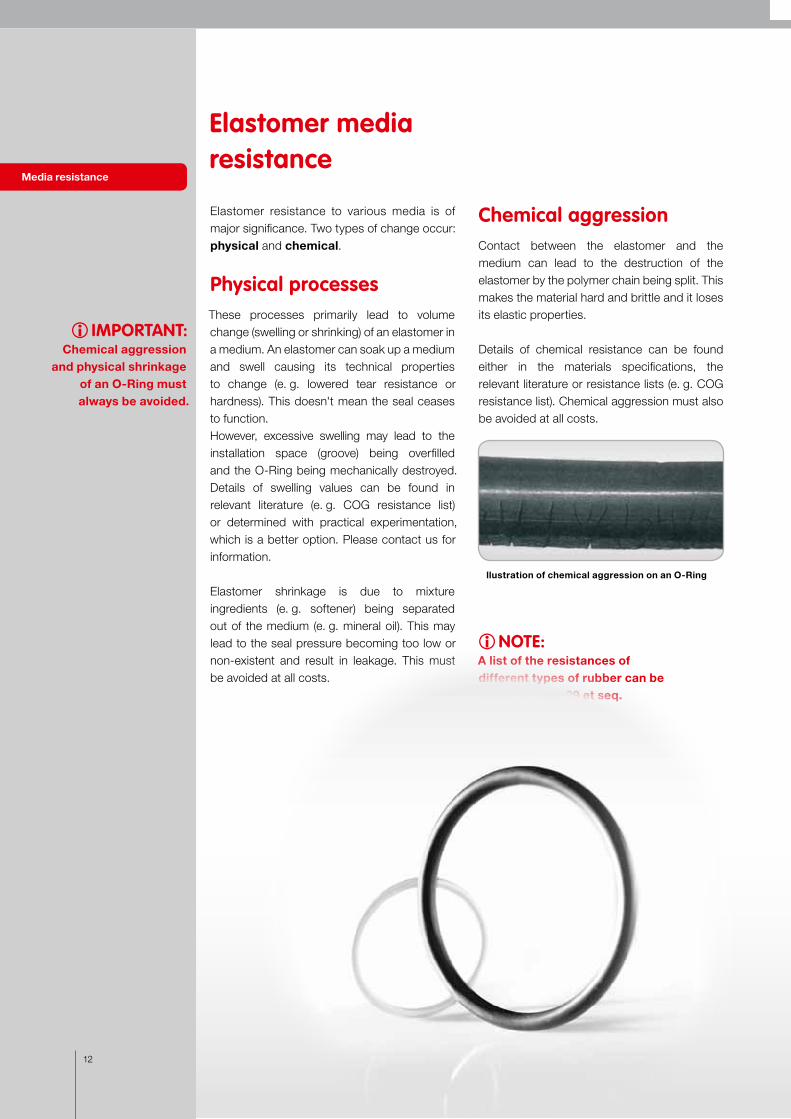
Elastomer resistance to various media is of major significance. Two types of change occur: physical and chemical.
Physical processesThese processes primarily lead to volume change (swelling or shrinking) of an elastomer in a medium. An elastomer can soak up a medium and swell causing its technical properties to change (e. g. lowered tear resistance or hardness). This doesn't mean the seal ceases to function.However, excessive swelling may lead to the installation space (groove) being overfilled and the O-Ring being mechanically destroyed.Details of swelling values can be found in relevant literature (e. g. COG resistance list) or determined with practical experimentation, which is a better option. Please contact us for information.
Elastomer shrinkage is due to mixture ingredients (e. g. softener) being separated out of the medium (e. g. mineral oil). This may lead to the seal pressure becoming too low or non-existent and result in leakage. This must be avoided at all costs.
Chemical aggressionContact between the elastomer and the medium can lead to the destruction of the elastomer by the polymer chain being split. This makes the material hard and brittle and it loses its elastic properties.
Details of chemical resistance can be found either in the materials specifications, the relevant literature or resistance lists (e. g. COG resistance list). Chemical aggression must also be avoided at all costs.
Media resistance
Elastomer media resistance
i IMPORTANT:Chemical aggression
and physical shrinkage of an O-Ring must always be avoided.
iNOTE:A list of the resistances of different types of rubber can be found on page 29 et seq.
llustration of chemical aggression on an O-Ring

Illustration of a typical rectangular groove
C
A
B P
B B
r 2
r1
thg
b
z
15°
to 2
0°
13
O-Rings must be laid in purpose-made grooves if they are to seal properly. These installation spaces are usually made with a rotary chisel in a shaft or drill hole, or with a milling machine in a workpiece. Groove geometry is usually rectangular.
The illustration below shows a typical rectangular groove with dimensions as recommended in the relevant standards.
Determining groove depth (t) The relationship of the O-Ring cross-section (d2) to the groove depth (t) determines the initial compression. The choice of groove depth depends on its intended use. In static use initial compression should be between 15 and 30 %. In dynamic use a smaller groove depth and hence lower compression should be chosen, usually between 6 and 20 %.
Determining groove width (b) Groove width (b) is determined by the O-Ring cross-section (d2) and the elliptical shape after compression plus a free space in which the medium can enter to guarantee even pressure on the seal.The main objective when selecting a size for the groove width is to avoid groove overfill. It is therefore usually assumed when designing the groove that the O-Ring should fill it by up to 85 % so that there is space for expansion (swelling, thermal extension), if needed.
Groove geometry for O-Ring installation spaces
i IMPORTANT:The groove depth has a decisive effect on O-Ring pressure.
iNOTE:The groove width needs to be adapted to a possible volume increase of the O-Ring.
Groove geometry
Key:t = groove depth b = groove widthh = height of the installation spaceg = size of gap to be sealed P = media pressureA = opposing surfaceB = groove flank surfaces and groove base C = surface of the insertion angler1 = radius in the base of the groove r2 = radius on the upper edge of the groove z = length of installation angle

14
There are various O-Ring installation options. The direction in which an O-Ring cross-section deforms depends on whether the ring is installed in axial or radial alignment. A differentiation is also made between radial deformation
"external seal" (internal groove, piston seal) and
O-Ring installation typesThe seal types for installation purposes are defined as follows
Installation types
Definition of installation types
"internal seal" (external groove, rod seal). Most O-Rings are statically stressed seals. If the seal is between machinery parts that move towards to each other then the seal is dynamic. O-Rings only present a technically optimal solution for dynamic seals in exceptional cases.
Flange seals / axial sealing
Piston seals / radial sealing
Rod seals / radial sealing
Flange seal:The groove is in the flange and is screwed down by a cover plate.
Piston seal:The groove is on the interior, which is called a piston seal.
Rod seal:The groove is on the exterior which is called a rod seal.
There are also specialised installations for specific situations such as
• Trapezoidal grooves• Triangular grooves

0° to 5°
15° to 20°
r2
ø d
4
r1
ø d
3
ø d
9
g
t
bz
ø x
Illustration of the installation space in a radial piston seal
Edges broken free of chatter marks
15
The diagram below shows a radial, static or dynamic installation of an O-Ring in a piston seal.
Radial, static or dynamic installationexternal seal (piston seal)
i IMPORTANT:This seal type is preferable in radial installation.
Installation types Piston seal
The following table provides more details about the names and installation spaces as well as the O-Ring.
Designation Tolerance Explanation
d4 H8 Drill hole diameter
d9 f7 Piston diameter (shaft diameter)
d3 h11 Inside diameter of the installation space (groove base diameter)
b + 0.25 Width of the O-Ring installation space (groove width)
g Gap size
t Radial depth of the installation space (groove depth)
r1 ± 0.1 ... 0.2 Radius in the base of the groove
r2 ± 0.1 Radius on the upper edge of the groove
z Length of installation angle ( > d2 / 2 )
16
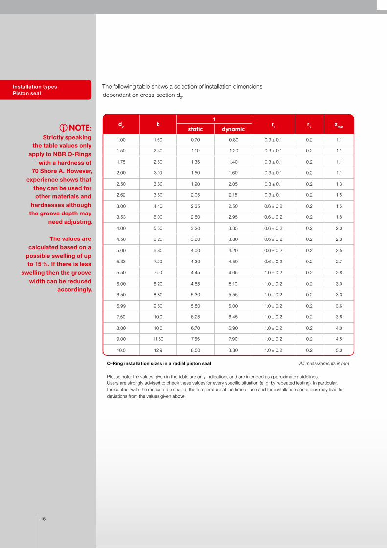
The following table shows a selection of installation dimensions dependant on cross-section d2.
O-Ring installation sizes in a radial piston seal All measurements in mm
Please note: the values given in the table are only indications and are intended as approximate guidelines. Users are strongly advised to check these values for every specific situation (e. g. by repeated testing). In particular, the contact with the media to be sealed, the temperature at the time of use and the installation conditions may lead to deviations from the values given above.
Installation types Piston seal
iNOTE:Strictly speaking
the table values only apply to NBR O-Rings
with a hardness of 70 Shore A. However,
experience shows that they can be used for other materials and
hardnesses although the groove depth may
need adjusting.
The values are calculated based on a
possible swelling of up to 15 %. If there is less
swelling then the groove width can be reduced
accordingly.
d2 bt
r1 r2 zminstatic dynamic
1.00 1.60 0.70 0.80 0.3 ± 0.1 0.2 1.1
1.50 2.30 1.10 1.20 0.3 ± 0.1 0.2 1.1
1.78 2.80 1.35 1.40 0.3 ± 0.1 0.2 1.1
2.00 3.10 1.50 1.60 0.3 ± 0.1 0.2 1.1
2.50 3.80 1.90 2.05 0.3 ± 0.1 0.2 1.3
2.62 3.80 2.05 2.15 0.3 ± 0.1 0.2 1.5
3.00 4.40 2.35 2.50 0.6 ± 0.2 0.2 1.5
3.53 5.00 2.80 2.95 0.6 ± 0.2 0.2 1.8
4.00 5.50 3.20 3.35 0.6 ± 0.2 0.2 2.0
4.50 6.20 3.60 3.80 0.6 ± 0.2 0.2 2.3
5.00 6.80 4.00 4.20 0.6 ± 0.2 0.2 2.5
5.33 7.20 4.30 4.50 0.6 ± 0.2 0.2 2.7
5.50 7.50 4.45 4.65 1.0 ± 0.2 0.2 2.8
6.00 8.20 4.85 5.10 1.0 ± 0.2 0.2 3.0
6.50 8.80 5.30 5.55 1.0 ± 0.2 0.2 3.3
6.99 9.50 5.80 6.00 1.0 ± 0.2 0.2 3.6
7.50 10.0 6.25 6.45 1.0 ± 0.2 0.2 3.8
8.00 10.6 6.70 6.90 1.0 ± 0.2 0.2 4.0
9.00 11.60 7.65 7.90 1.0 ± 0.2 0.2 4.5
10.0 12.9 8.50 8.80 1.0 ± 0.2 0.2 5.0

17
Determining the inside diameter d1
In static or dynamic radial external O-Ring seals the inside diameter d1 must be approximately 1 – 6 % smaller than the groove base diameter d3. This means that the O-Ring should be installed slightly stretched.
The diagrams below show the permissible ranges of O-Ring compression depending on cross-section d2.
i IMPORTANT:The O-Ring should be installed slightly stretched.
Inside diameter Piston seal
Dynamic seal compression
Static seal compression
Verpressungsdiagramm einer hydraulischen,dynamischen Anwendung
Verpressungsdiagramm einer hydraulischenstatischen Anwendung
Verpressungsdiagramm einer hydraulischen,dynamischen Anwendung
Verpressungsdiagramm einer hydraulischenstatischen Anwendung
Compression diagram for a hydraulic static application.
Compression diagram for a hydraulic dynamic application.
VP
d2d2
VP
VP in %d2 in mm
18
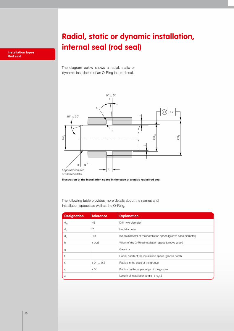
The diagram below shows a radial, static or dynamic installation of an O-Ring in a rod seal.
Installation types Rod seal
Radial, static or dynamic installation,internal seal (rod seal)
Illustration of the installation space in the case of a static radial rod seal
The following table provides more details about the names and installation spaces as well as the O-Ring.
Designation Tolerance Explanation
d10 H8 Drill hole diameter
d5 f7 Rod diameter
d6 H11 Inside diameter of the installation space (groove base diameter)
b + 0.25 Width of the O-Ring installation space (groove width)
g Gap size
t Radial depth of the installation space (groove depth)
r1 ± 0.1 ... 0.2 Radius in the base of the groove
r2 ± 0.1 Radius on the upper edge of the groove
z Length of installation angle ( > d2 / 2 )
ø x
0° to 5°
15° to 20°
r1
r2
ø d
6
ø d 10
ø d
5
g
b
z
t
Edges broken free of chatter marks
19
Installation types Rod seal
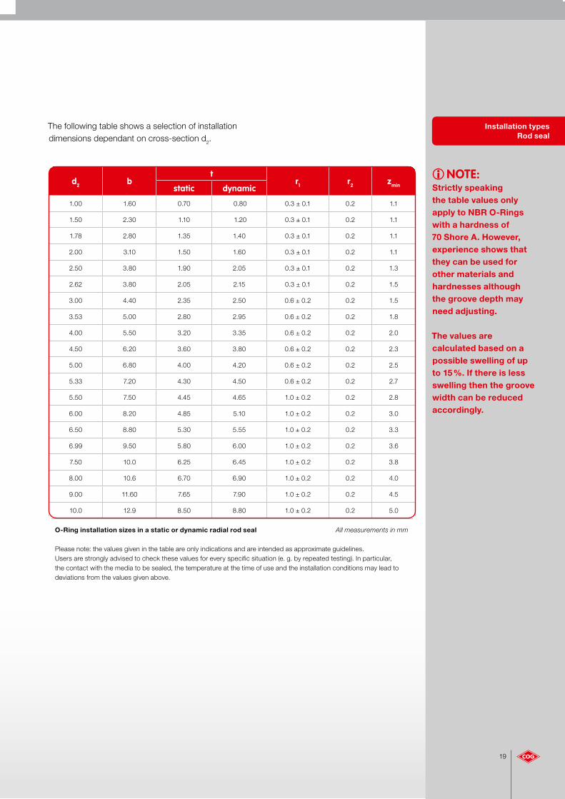
The following table shows a selection of installation dimensions dependant on cross-section d2.
O-Ring installation sizes in a static or dynamic radial rod seal All measurements in mm
Please note: the values given in the table are only indications and are intended as approximate guidelines. Users are strongly advised to check these values for every specific situation (e. g. by repeated testing). In particular, the contact with the media to be sealed, the temperature at the time of use and the installation conditions may lead to deviations from the values given above.
iNOTE:Strictly speaking the table values only apply to NBR O-Rings with a hardness of 70 Shore A. However, experience shows that they can be used for other materials and hardnesses although the groove depth may need adjusting.
The values are calculated based on a possible swelling of up to 15 %. If there is less swelling then the groove width can be reduced accordingly.
d2 bt
r1 r2 zminstatic dynamic
1.00 1.60 0.70 0.80 0.3 ± 0.1 0.2 1.1
1.50 2.30 1.10 1.20 0.3 ± 0.1 0.2 1.1
1.78 2.80 1.35 1.40 0.3 ± 0.1 0.2 1.1
2.00 3.10 1.50 1.60 0.3 ± 0.1 0.2 1.1
2.50 3.80 1.90 2.05 0.3 ± 0.1 0.2 1.3
2.62 3.80 2.05 2.15 0.3 ± 0.1 0.2 1.5
3.00 4.40 2.35 2.50 0.6 ± 0.2 0.2 1.5
3.53 5.00 2.80 2.95 0.6 ± 0.2 0.2 1.8
4.00 5.50 3.20 3.35 0.6 ± 0.2 0.2 2.0
4.50 6.20 3.60 3.80 0.6 ± 0.2 0.2 2.3
5.00 6.80 4.00 4.20 0.6 ± 0.2 0.2 2.5
5.33 7.20 4.30 4.50 0.6 ± 0.2 0.2 2.7
5.50 7.50 4.45 4.65 1.0 ± 0.2 0.2 2.8
6.00 8.20 4.85 5.10 1.0 ± 0.2 0.2 3.0
6.50 8.80 5.30 5.55 1.0 ± 0.2 0.2 3.3
6.99 9.50 5.80 6.00 1.0 ± 0.2 0.2 3.6
7.50 10.0 6.25 6.45 1.0 ± 0.2 0.2 3.8
8.00 10.6 6.70 6.90 1.0 ± 0.2 0.2 4.0
9.00 11.60 7.65 7.90 1.0 ± 0.2 0.2 4.5
10.0 12.9 8.50 8.80 1.0 ± 0.2 0.2 5.0

20
Inside diameter Rod seal
Installation types Flange seals
VP in %d2 in mm
Dynamic seal compression
Verpressungsdiagramm einer hydraulischen,dynamischen Anwendung
Verpressungsdiagramm einer hydraulischenstatischen Anwendung
Compression diagram for a hydraulic dynamic application.
VP
d2
Static seal compression
Verpressungsdiagramm einer hydraulischen,dynamischen Anwendung
Verpressungsdiagramm einer hydraulischenstatischen Anwendung
Compression diagram for a hydraulic static application.
d2
VP
Determining the inside diameter d1
In static or dynamic radial internal O-Ring seals the inside diameter d1 must be approximately 1 – 3 % larger than the external diameter d6. This means that the O-Ring should be installed slightly stretched.
The diagrams below show the permissible ranges of the O-Ring compression depending on cross-section d2.
The diagram below shows the installation space in axial flange seals.
The following table provides more details about the names and installation spaces as well as the O-Ring.
Axial, static installation (flange seal)
Illustration of axial seal installation space
i IMPORTANT:The O-Ring should
be installed slightly compressed.
Designation Tolerance Explanation
d7 H11 External axial diameter
d8 h11 Internal axial diameter
b4 + 0.20 With of the O-Ring installation space (groove width)
h + 0.1 Radial depth of the installation space (groove depth)
r1 ± 0.1... 0.2 Radius in the base of the groove
r2 ± 0.1 Radius on the upper edge of the groove
r2
r1
ø d8
b4
h
ø d7
21
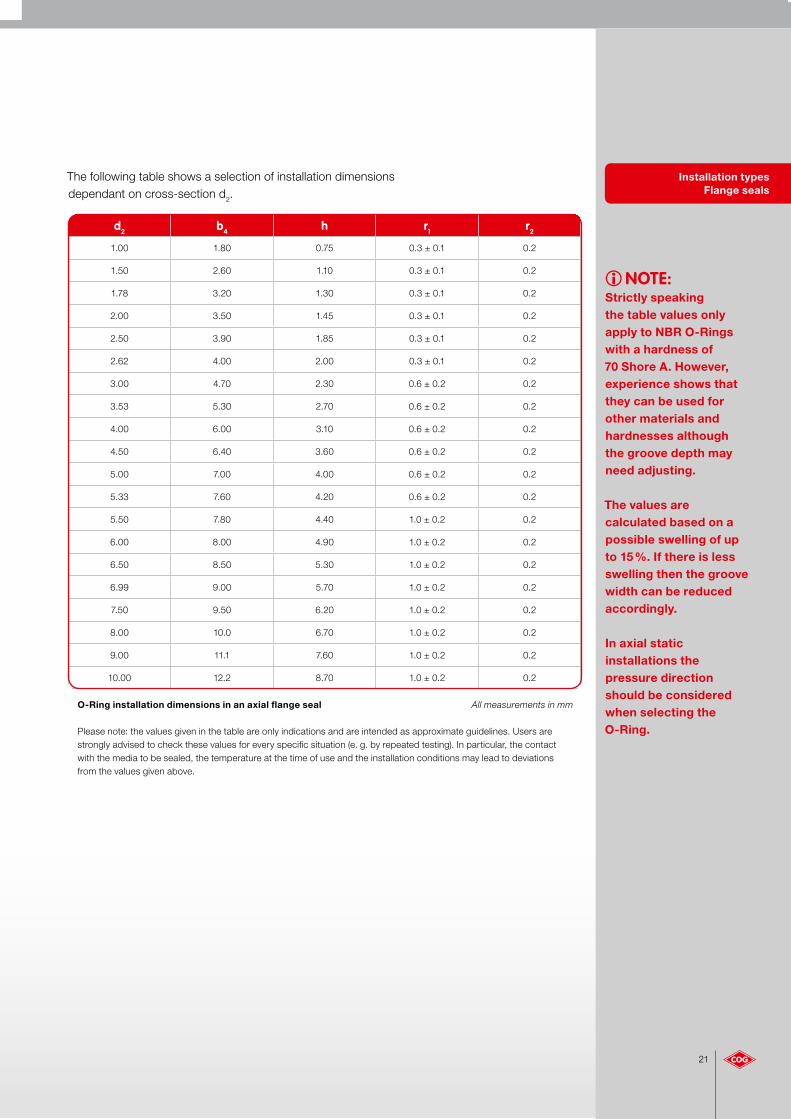
iNOTE:Strictly speaking the table values only apply to NBR O-Rings with a hardness of 70 Shore A. However, experience shows that they can be used for other materials and hardnesses although the groove depth may need adjusting.
The values are calculated based on a possible swelling of up to 15 %. If there is less swelling then the groove width can be reduced accordingly.
In axial static installations the pressure direction should be considered when selecting the O-Ring.
Installation types Flange seals
The following table shows a selection of installation dimensionsdependant on cross-section d2.
O-Ring installation dimensions in an axial flange seal All measurements in mm
Please note: the values given in the table are only indications and are intended as approximate guidelines. Users are strongly advised to check these values for every specific situation (e. g. by repeated testing). In particular, the contact with the media to be sealed, the temperature at the time of use and the installation conditions may lead to deviations from the values given above.
d2 b4 h r1 r2
1.00 1.80 0.75 0.3 ± 0.1 0.2
1.50 2.60 1.10 0.3 ± 0.1 0.2
1.78 3.20 1.30 0.3 ± 0.1 0.2
2.00 3.50 1.45 0.3 ± 0.1 0.2
2.50 3.90 1.85 0.3 ± 0.1 0.2
2.62 4.00 2.00 0.3 ± 0.1 0.2
3.00 4.70 2.30 0.6 ± 0.2 0.2
3.53 5.30 2.70 0.6 ± 0.2 0.2
4.00 6.00 3.10 0.6 ± 0.2 0.2
4.50 6.40 3.60 0.6 ± 0.2 0.2
5.00 7.00 4.00 0.6 ± 0.2 0.2
5.33 7.60 4.20 0.6 ± 0.2 0.2
5.50 7.80 4.40 1.0 ± 0.2 0.2
6.00 8.00 4.90 1.0 ± 0.2 0.2
6.50 8.50 5.30 1.0 ± 0.2 0.2
6.99 9.00 5.70 1.0 ± 0.2 0.2
7.50 9.50 6.20 1.0 ± 0.2 0.2
8.00 10.0 6.70 1.0 ± 0.2 0.2
9.00 11.1 7.60 1.0 ± 0.2 0.2
10.00 12.2 8.70 1.0 ± 0.2 0.2
22
Verpressungsdiagramm einer hydraulischen axialen Anwendung
Inside diameter Flange seals
VP in %d2 in mm
Static seal compression
Compression diagram for a hydraulic axial application.
d2
VP
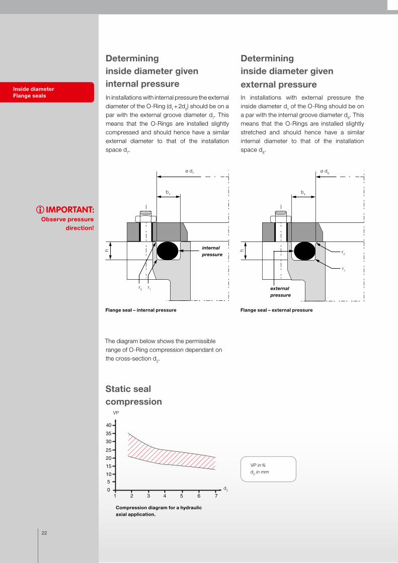
Determining inside diameter given internal pressureIn installations with internal pressure the external diameter of the O-Ring (d1 + 2d2) should be on a par with the external groove diameter d7. This means that the O-Rings are installed slightly compressed and should hence have a similar external diameter to that of the installation space d7.
Determining inside diameter givenexternal pressureIn installations with external pressure the inside diameter d1 of the O-Ring should be on a par with the internal groove diameter d8. This means that the O-Rings are installed slightly stretched and should hence have a similar internal diameter to that of the installation space d8.
i IMPORTANT:Observe pressure
direction!
Flange seal – internal pressure Flange seal – external pressure
The diagram below shows the permissible range of O-Ring compression dependant on the cross-section d2.
internal pressure
r2 r1
ø d7
b4
h
external pressure
r2
r1
ø d8
b4
h
23
Trapezoidal groove
Triangular groove
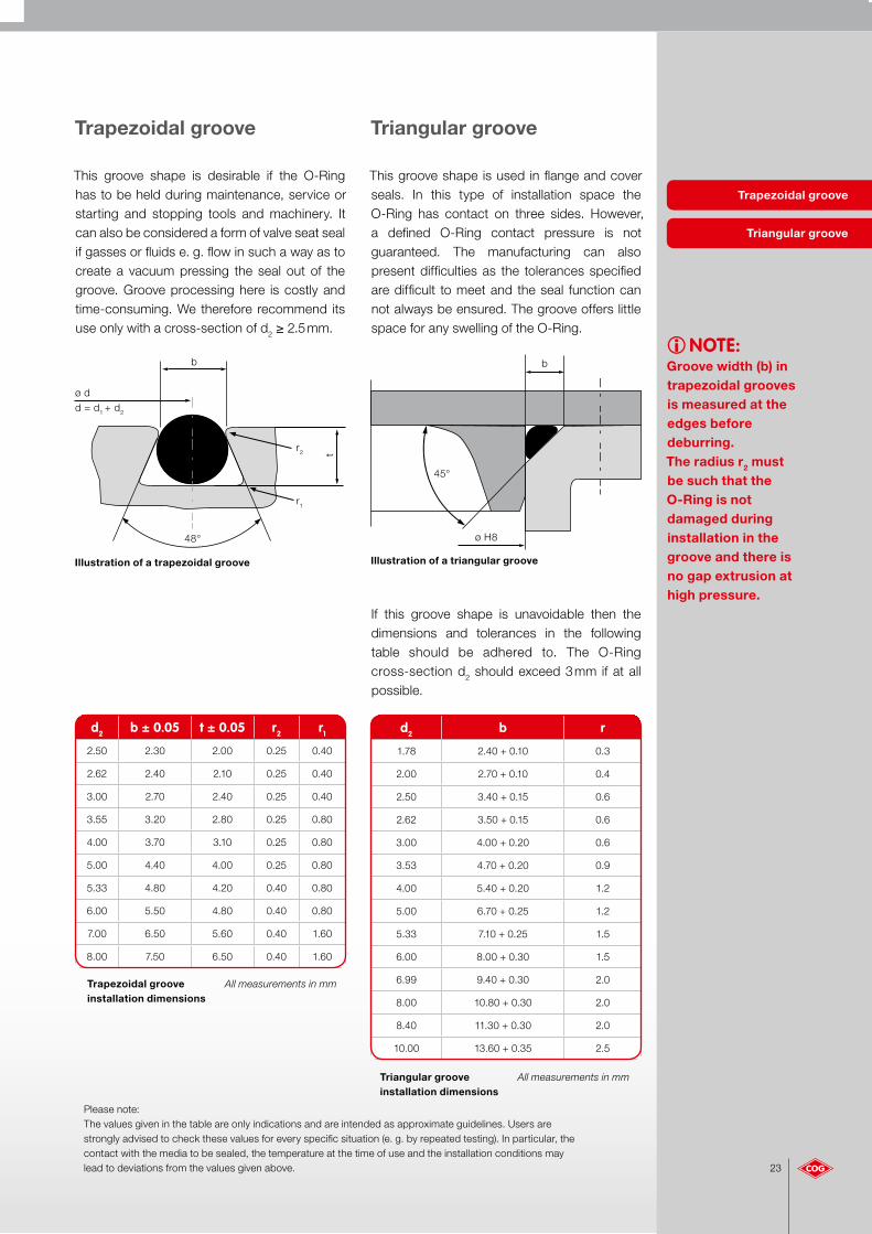
This groove shape is desirable if the O-Ring has to be held during maintenance, service or starting and stopping tools and machinery. It can also be considered a form of valve seat seal if gasses or fluids e. g. flow in such a way as to create a vacuum pressing the seal out of the groove. Groove processing here is costly and time-consuming. We therefore recommend its use only with a cross-section of d2 ≥ 2.5 mm.
This groove shape is used in flange and cover seals. In this type of installation space the O-Ring has contact on three sides. However, a defined O-Ring contact pressure is not guaranteed. The manufacturing can also present difficulties as the tolerances specified are difficult to meet and the seal function can not always be ensured. The groove offers little space for any swelling of the O-Ring.
If this groove shape is unavoidable then the dimensions and tolerances in the following table should be adhered to. The O-Ring cross-section d2 should exceed 3 mm if at all possible.
Trapezoidal groove Triangular groove
Illustration of a trapezoidal groove Illustration of a triangular groove
Triangular groove All measurements in mminstallation dimensions
Trapezoidal groove All measurements in mminstallation dimensions
iNOTE:Groove width (b) intrapezoidal groovesis measured at theedges beforedeburring.The radius r2 must be such that the O-Ring is not damaged during installation in the groove and there is no gap extrusion at high pressure.
d2 b r
1.78 2.40 + 0.10 0.3
2.00 2.70 + 0.10 0.4
2.50 3.40 + 0.15 0.6
2.62 3.50 + 0.15 0.6
3.00 4.00 + 0.20 0.6
3.53 4.70 + 0.20 0.9
4.00 5.40 + 0.20 1.2
5.00 6.70 + 0.25 1.2
5.33 7.10 + 0.25 1.5
6.00 8.00 + 0.30 1.5
6.99 9.40 + 0.30 2.0
8.00 10.80 + 0.30 2.0
8.40 11.30 + 0.30 2.0
10.00 13.60 + 0.35 2.5
d2 b ± 0.05 t ± 0.05 r2 r1
2.50 2.30 2.00 0.25 0.40
2.62 2.40 2.10 0.25 0.40
3.00 2.70 2.40 0.25 0.40
3.55 3.20 2.80 0.25 0.80
4.00 3.70 3.10 0.25 0.80
5.00 4.40 4.00 0.25 0.80
5.33 4.80 4.20 0.40 0.80
6.00 5.50 4.80 0.40 0.80
7.00 6.50 5.60 0.40 1.60
8.00 7.50 6.50 0.40 1.60
ø dd = d1 + d2
48°
b
r2 t
r1
45°
b
ø H8
Please note: The values given in the table are only indications and are intended as approximate guidelines. Users are strongly advised to check these values for every specific situation (e. g. by repeated testing). In particular, the contact with the media to be sealed, the temperature at the time of use and the installation conditions may lead to deviations from the values given above.

24
Installation anglesTo avoid O-Ring damage during installation installation angles for drill holes and shafts must be considered during the design stage.
The primary installation tips at a glance:
• Never pull O-Rings over sharp edges
• There must not be any dirt or residue in the groove or on the O-Ring
• Avoid any potential confusion with other O-Rings (see colour coding if present)
• Never use adhesive on an O-Ring (possible hardening)
• Do not go over drill holes
• Whenever possible use installation grease/oil. But the material must be resistance against the grease (e. g. do not use mineral oil/Vaseline with EPDM!)
• Detergents/cleansers must be checked for O-Ring compatibility.
• Do not use any hard or sharp-edged tools
• Short-term expansion of the O-Ring's inside diameter by as much as 20 % is permissible for installation purposes
O-Rings are very sensitive to sharp edges. All edges over which the O-Ring is to be pulled or against which it will press must therefore be rounded or deburred. This is a major condition for safe installation.
O-Ring installation types
O-Ring installation
Installation angles
The table below shows the minimum lengthsof the installation angle for piston and rod sealsdependant on cross-section d2.
Minimum installation angle lengths
d2 z at 15° z at 20°to 1.80 2.5 2.0
1.81 – 2.62 3.0 2.5
2.63 – 3.53 3.5 3.0
3.54 – 5.33 4.0 3.5
5.34 – 7.00 5.0 4.0
over 7.01 6.0 4.5
Installation angle for piston seals
Installation direction
z
15° to 20°
Installation angle for rod seals
15° to 20°
z
Installation direction
All
mea
sure
men
ts in
mm
25
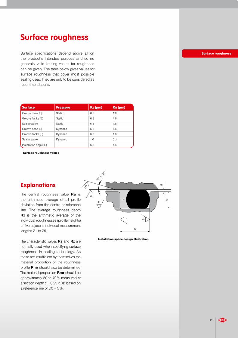
Surface roughnessSurface specifications depend above all on the product's intended purpose and so no generally valid limiting values for roughness can be given. The table below gives values for surface roughness that cover most possible sealing uses. They are only to be considered as recommendations.
Surface roughness
Surface roughness values
Explanations The central roughness value Ra is the arithmetic average of all profile deviation from the centre or reference line. The average roughness depth Rz is the arithmetic average of the individual roughnesses (profile heights) of five adjacent individual measurement lengths Z1 to Z5.
The characteristic values Ra and Rz are normally used when specifying surface roughness in sealing technology. As these are insufficient by themselves the material proportion of the roughness profile Rmr should also be determined. The material proportion Rmr should be approximately 50 to 70 % measured at a section depth c = 0.25 x Rz, based on a reference line of C0 = 5 %.
Installation space design illustration
Surface Pressure Rz (µm) Ra (µm)Groove base (B) Static 6.3 1.6
Groove flanks (B) Static 6.3 1.6
Seal area (A) Static 6.3 1.6
Groove base (B) Dynamic 6.3 1.6
Groove flanks (B) Dynamic 6.3 1.6
Seal area (A) Dynamic 1.6 0..4
Installation angle (C) -- 6.3 1.6
15° t
o 20
°
g
h
B B
b
C
A
BP

26
PTFE O-Rings The installation space design for O-Rings made from thermoplastic PTFE material is detailed below.
The following diagram shows the installation space for static axial installation.
PTFE O-Rings are closed rings of circular cross-section. Dimensions are characterised by the inside diameter d1 and the cross-section d2.
PTFE O-Rings are not form-compressed but manufactured under tension and differ in this fact from elastomer O-Rings. They can hence be made in any size.
The following table provides more details about the names and installation spaces as well as the O-Ring.
The following table shows a selection of dimensions for groove width (b) and depth (t) dependant on cross-section d2.
Installation dimensions for PTFE O-Rings
Installation space for PTFE O-Rings
iNOTE:PTFE O-Rings have
little elasticity. The O-Rings used
should hence have dimensions
identical to the nominal dimensions
to be sealed. Installation ought
preferably to be in axially easily
accessible grooves.
d2 b + 0,1 h + 0,05 r1
1.00 1.20 0.85 0.2
1.50 1.70 1.30 0.2
1.80 2.00 1.60 0.4
2.00 2.20 1.80 0.5
2.50 2.80 2.25 0.5
2.65 2.90 2.35 0.6
3.00 3.30 2.70 0.8
3.55 3.90 3.15 1.0
4.00 4.40 3.60 1.0
5.00 5.50 4.50 1.0
5.30 5.90 4.80 1.2
6.00 6.60 5.60 1.2
7.00 7.70 6.30 1.5
8.00 8.80 7.20 1.5
Designation Explanation d1 O-Ring inside diameter
d2 Cross-section
b Width of the O-Ring installation space (groove width)
h Radial depth of the installationspace (groove depth)
r1 Radius at the base of theinstallation space
Illustration of an installation space for PTFE O-Rings
r1
h
b
r1
Illustration of PTFE O-Rings
ø d1
d2
All
mea
sure
men
ts in
mm
27
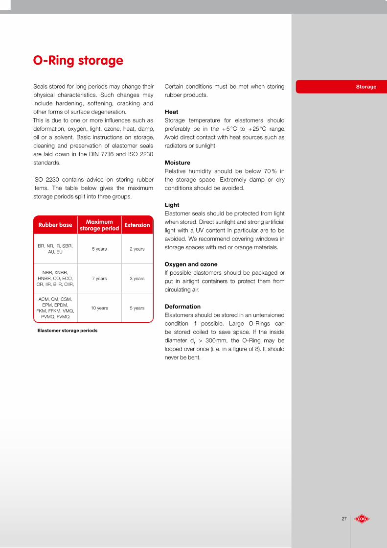
StorageSeals stored for long periods may change their physical characteristics. Such changes may include hardening, softening, cracking and other forms of surface degeneration. This is due to one or more influences such as deformation, oxygen, light, ozone, heat, damp, oil or a solvent. Basic instructions on storage, cleaning and preservation of elastomer seals are laid down in the DIN 7716 and ISO 2230 standards.
ISO 2230 contains advice on storing rubber items. The table below gives the maximum storage periods split into three groups.
Elastomer storage periods
HeatStorage temperature for elastomers should preferably be in the + 5 °C to + 25 °C range. Avoid direct contact with heat sources such as radiators or sunlight.
MoistureRelative humidity should be below 70 % in the storage space. Extremely damp or dry conditions should be avoided.
LightElastomer seals should be protected from light when stored. Direct sunlight and strong artificial light with a UV content in particular are to be avoided. We recommend covering windows in storage spaces with red or orange materials.
Oxygen and ozoneIf possible elastomers should be packaged or put in airtight containers to protect them from circulating air.
DeformationElastomers should be stored in an untensioned condition if possible. Large O-Rings can be stored coiled to save space. If the inside diameter d1 > 300 mm, the O-Ring may be looped over once (i. e. in a figure of 8). It should never be bent.
Certain conditions must be met when storing rubber products.
O-Ring storage
Rubber base Maximumstorage period Extension
BR, NR, IR, SBR, AU, EU
5 years 2 years
NBR, XNBR, HNBR, CO, ECO, CR, IIR, BIIR, CIIR,
7 years 3 years
ACM, CM, CSM, EPM, EPDM,
FKM, FFKM, VMQ, PVMQ, FVMQ
10 years 5 years

28
Surface treatment
"Labs-free" O-Rings
O-Rings can be subjected to special surface treatment e. g. to adjust adhesion, reduce friction or simplify installation.
The following benefits may be accrued depending on the individual case and the coating procedure used:
• Better separation
• Assembly simplification
• Anti-adhesion effect
• Friction reduction / reduction of wear and tear
• Silicone and paint cross-linking malfunction prevention
• Improvement in lubrication characteristics
• Stick-slip reduction
• Reduction of breakaway force
• Simplification of automated installation
"Labs-free" O-Rings "Labs-free" O-Rings are free of substances which cause paint cross-linking malfunctions. Such O-Rings are particularly suitable for use in compressed air systems used in painting engineering and above all in the automotive industry. Elastomers may contain substances which cause paint cross-linking to malfunction. The causatory substances can be released into the air or by contact with elastomers and then land on the surface(s) to be painted and cause irregularities. The O-Rings intended for this use are hence subjected to a special treatment to ensure they are free of such substances.
Surface treatment
Caption: Coating options and their typical uses
Designation Type of coating Coating purpose
PTFE-ME PTFE transparent Installation simplification
PTFE-FDA PTFE milky-white Mounting aid
PTFE transparent PTFE transparent Conditionally dynamic use
PTFE-black PTFE-black Dynamic use
PTFE-grey PTFE-grey Dynamic use
Polysiloxane Silicon resin Mounting aid
Siliconise Silicon oil Installation simplification
Talcum powder Talcum powder Installation simplification
Molycoting MoS2 powder Installation simplification
Graphiting Graphite powder Installation simplification

29
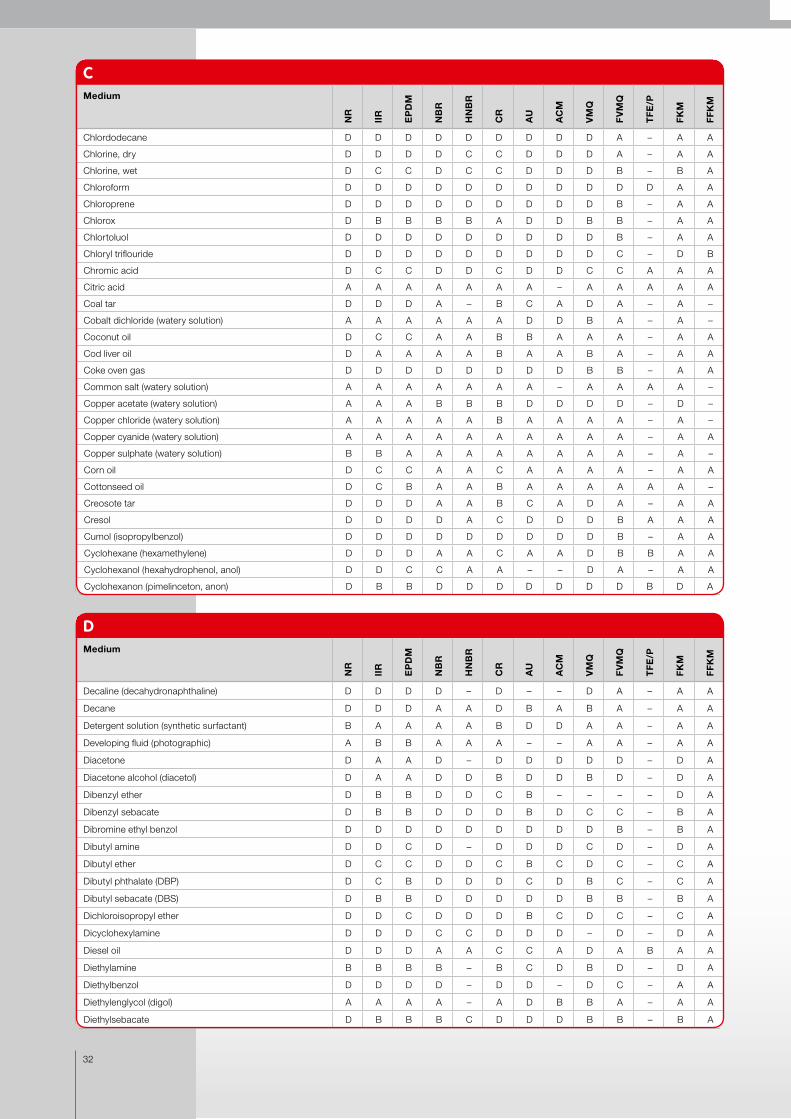
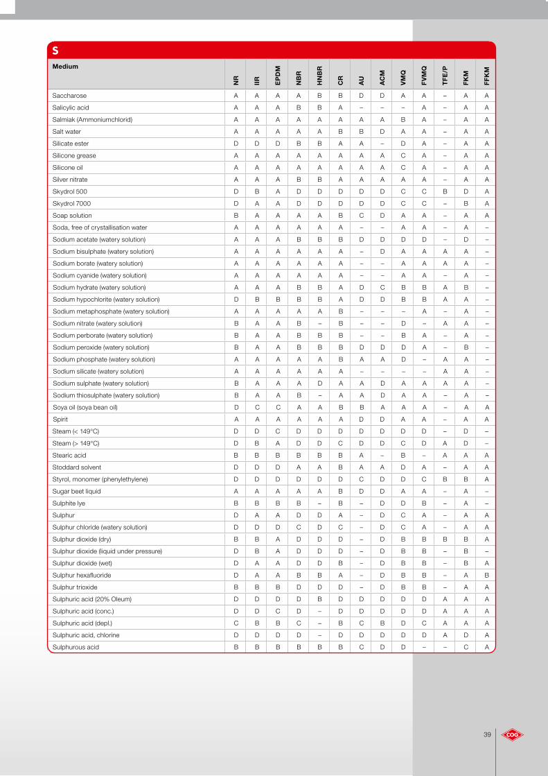
This list uses a rating system to show the chemical resistance of the elastomer products we supply to different operating media. The following data is based on tests and information provided by our suppliers and customers.Because of the different application conditions and composition of the media, this data must only be regarded as a guide.
Chemical resistance list
The data is nonbinding and must be checked on a case-by-case basis.With a view to the safe choice of materials we recommend you carry out resistance tests under the conditions of use. For further information, please refer to our product datasheets or contact our application technology department.
The specific data are to be understood as follows:A = 0 – 5 % volume swelling, elastomer shows zero to small swelling.B = 5 – 10 % volume swelling, elastomer shows small to moderate swellingC = 10 – 20 % volume swelling, elastomer shows moderate to strong swellingD = Not recommended– = Unknown / Not checked
Chemical resistance list
AMedium
NR
IIR
EP
DM
NB
R
HN
BR
CR
AU
AC
M
VM
Q
FV
MQ
TF
E/P
FK
M
FF
KM
Acetaldehyde B A A D – C D D B D – D A
Acetamide D A A A A B D D B A A B A
Acetic acid (30%) B B A B – A D D A B – B –
Acetic acid, Glacial acetic acid B B A C B D D D B D – C
Acetic anhydride B B B C D B D D C D B D A
Acetone C A A D D C D D C D D D A
Acetophenone D A A D D D D D D D – D A
Acetylchloride D D D D D D D D C A – A A
Acetylene B A A A – B D D B – – A A
Acrylnitrile D D D D D D D D D D – C A
Adipic acid (E 355) A A A A A A – – – A – A A
Aluminium acetate (watery solution) A A A B – B D D D D – D A
Aluminium chloride (watery solution) A A A A A A C A B A – A A
Aluminium fluoride (watery solution) B A A A A A C – B A – A A
Aluminium nitrate (watery solution) A A A A A A C – B – – A A
Aluminium phosphate (watery solution) A A A A A A – – A – – A A
Aluminium sulphate (watery solution) A A A A A A D D A A – A A
Ammonia (gaseous, cold) D B B D D B D D A D – D A
Ammonia (gaseous, hot) A A A A A A C D A D A D A
Ammonia, water-free D A A B B A D D C D – D A
Ammonium carbonate (watery solution) A A – D D A D D – – A A A
Ammonium chloride (watery solution) A A A A A A A – – – – A A
Ammonium hydroxide (concentrated) D A A D – A D D A B – B A
Ammonium nitrate (watery solution) C A A A A A D B – – A A A
Ammonium nitrite (watery solution) A A A A A A – – B – – A A
Ammonium persulphate (watery solution) A A A D D A D D – – – A A

30
AMedium
NR
IIR
EP
DM
NB
R
HN
BR
CR
AU
AC
M
VM
Q
FV
MQ
TF
E/P
FK
M
FF
KM
Ammonium phosphate (watery solution) A A A A – A – – A – – A A
Ammonium sulphate (watery solution) A A A A A A A D – – – B A
Amyl acetate D C C D D D D D D D – D A
Amyl acetate D C C D D D D D D D – D A
Amyl alcohol (pentanol) B A A B B B D D D A – B A
Amyl borate D D D A A A – – – – – A A
Amyl chlornaphthaline D D D D D D D D D B – A A
Amyl naphthaline D D D D D D D B D A – A A
Aniline D A A D – D D D D C A C A
Aniline dye B B A D D B D D C B – B A
Aniline hydrochloride B B B B – D D D D B – B A
Animal fats D B B A A B A A B A – A A
Ansul ether (anaesthetic) D C C C C D B D D C – D –
AROCLOR 1248 D C C C C D D D B B – A –
AROCLOR 1254 D D C D D D D D C B – A –
AROCLOR 1260 A A A A A A D D B A – A –
Arsenic trichloride (watery solution) D C C A A A – – – – – D –
Arsenical acid B A A A A A C C A A – A –
Askarel transformer oil D D D B B D D D D B – A –
Asphalt (DIN 55946) D D D B – B B B D B – A A
Azotic A A A A – A A A A A – A B
Azotic acid (conc.) D D D D D D D D D C B B A
Azotic acid (depl.) D B B D – B C D B B B A A
Azotic acid (red fuming) D D D D D D D D D D B C B
BMedium
NR
IIR
EP
DM
NB
R
HN
BR
CR
AU
AC
M
VM
Q
FV
MQ
TF
E/P
FK
M
FF
KM
Baking soda (watery solution) A A A A A A – – A A – A –
Barium chloride (watery solution) A A A A A A A A A A – A A
Barium hydroxide (watery solution) A A A A A A D D A A – A A
Barium sulphate (watery solution) A A A A A A A D A A – A A
Barium sulphide (watery solution) A A A A A A A D A A – A A
Beer A A A A A A B D A A – A –
Benzaldehyde (artificial bitter almond oil) D A A D D D D D B C B D B
Benzene (nitrobenzene, ligroin) D D D A – B B A D A – A A
Benzensulfonic D D C D – B D D D B – A B
Benzoic acid (E 210) D D C C – D D C C B – A A
Benzyl D D D D D D C D D C C A A
Benzyl alcohol D A A D – B D D B B A A A
Benzyl benzoate D B B D – D – D – A – A A
Benzyl chloride D D D D – D – D – B – B A
Biphenyl (Diphenyl, Phenylbenzol) D D D D D D D D D B – A A
Blast furnace gas D D D D D D D D A B – A A
Bleach D A A D B D D D B B A A A
Borax solution (disodium tetra borate) B A A B A A A B B B – A A
Bordeaux solution B A A B – B D D B B – A A
Boric acid A A A A A A A D A A – A A
Bromhydric acid A A A D D D D D D C – A A
Bromhydric acid (40%) A A A D – B D D D C – A A

31
CMedium
NR
IIR
EP
DM
NB
R
HN
BR
CR
AU
AC
M
VM
Q
FV
MQ
TF
E/P
FK
M
FF
KM
Calcium acetate (watery solution) A A A B B B D D D D A D –
Calcium carbonate sulphur solution D A A D A A – D A A – A A
Calcium chloride (watery solution) A A A A A A A A A A A A A
Calcium hydrogen sulphite (watery solution) D D D D A A A D A A – A A
Calcium hydroxide (watery solution) A A A A A A A D A A A A A
Calcium hypochlorite (watery solution) C A A B B C D D B B A A A
Calcium nitrate (watery solution) A A A A A A A A B A A A A
Calcium sulphide (watery solution) B A A A A A A D B A A A A
Carbamate D B B C – B D D – A – A A
Carbitol (ethyldiglycol) B B B B – B D D B B – B A
Carbolic acid (phenol) D B B D D C C D D A – A A
Carbon dioxide B B B A A B A – B A – A –
Carbon disulphide D D D C D D – C D A A A A
Carbon monoxide B A A A A B A A A B – A A
Carbon tetrachloride D D D C B D D D D C D A B
Carbonic acid A A A B A A A A A A – A A
Caster oil A B B A A A A A A A A A A
Cattle feed oil D B B A A D A A B A – A A
Cellosolve (ethyleneglycolether) D B B D – D D D D D – C A
Cellosolve acetate (glycol acetate) D B B D D D D D D D – D A
Cellulube (fyrquel) D A A D D D D D A C – A –
Chloracetic acid D B A D D D D D – D – D A
China wood oil (China Tung oil) D C C A A B C – D B – A A
Chloroacetone D B A D D C D D D D – D A
Chlorobenzene D D D D D D D D D B – A A
Chlorine dioxide D C C D D D D D – B – A A
BMedium
NR
IIR
EP
DM
NB
R
HN
BR
CR
AU
AC
M
VM
Q
FV
MQ
TF
E/P
FK
M
FF
KM
Bromine fluid D C B D C D D D D B – A –
Bromineine benzyl D D D D D D D D D A – A A
Bromineine trifluoride D D D D D D D D D D – D B
Bromineine, water-free D D D D – D D D D B – A –
Bromochloromethane D B B D D D D D D B – A A
Bunker oil D D D A A D B A B A – A A
Butadiene D D C D – D D D D B – A –
Butane D D D A A A A A D A – A A
Butter (animal fat) D B A A A B A A B A – A –
Butyl acetate D C C D – D D D D D D D –
Butyl acrylate D D D D D D – D – D – D –
Butyl alcohol (butanol) A B B A A A D D B B A A –
Butyl amine D C B C C D D D D D – D A
Butyl benzoate C B B D – D – D – A – A A
Butyl ethyl diglycol (CARBITOL) D A A D D C – D D D – C –
Butylacetylricinoleate D A A C B B D – – B – A –
Butylene (butene) D D D B D C D D D B – A –
Butylglycolether (CELLOSOLVE) D A A C C C D D – D – D –
Butyloleate D B B D D D – – – B – A A
Butylstearate D C C B B D – – – B A A –
Butyraldehyde (butanal) D B B D – C D D D D – D –
32
CMedium
NR
IIR
EP
DM
NB
R
HN
BR
CR
AU
AC
M
VM
Q
FV
MQ
TF
E/P
FK
M
FF
KM
Chlordodecane D D D D D D D D D A – A A
Chlorine, dry D D D D C C D D D A – A A
Chlorine, wet D C C D C C D D D B – B A
Chloroform D D D D D D D D D D D A A
Chloroprene D D D D D D D D D B – A A
Chlorox D B B B B A D D B B – A A
Chlortoluol D D D D D D D D D B – A A
Chloryl triflouride D D D D D D D D D C – D B
Chromic acid D C C D D C D D C C A A A
Citric acid A A A A A A A – A A A A A
Coal tar D D D A – B C A D A – A –
Cobalt dichloride (watery solution) A A A A A A D D B A – A –
Coconut oil D C C A A B B A A A – A A
Cod liver oil D A A A A B A A B A – A A
Coke oven gas D D D D D D D D B B – A A
Common salt (watery solution) A A A A A A A – A A A A –
Copper acetate (watery solution) A A A B B B D D D D – D –
Copper chloride (watery solution) A A A A A B A A A A – A –
Copper cyanide (watery solution) A A A A A A A A A A – A A
Copper sulphate (watery solution) B B A A A A A A A A – A –
Corn oil D C C A A C A A A A – A A
Cottonseed oil D C B A A B A A A A A A –
Creosote tar D D D A A B C A D A – A A
Cresol D D D D A C D D D B A A A
Cumol (isopropylbenzol) D D D D D D D D D B – A A
Cyclohexane (hexamethylene) D D D A A C A A D B B A A
Cyclohexanol (hexahydrophenol, anol) D D C C A A – – D A – A A
Cyclohexanon (pimelinceton, anon) D B B D D D D D D D B D A
DMedium
NR
IIR
EP
DM
NB
R
HN
BR
CR
AU
AC
M
VM
Q
FV
MQ
TF
E/P
FK
M
FF
KM
Decaline (decahydronaphthaline) D D D D – D – – D A – A A
Decane D D D A A D B A B A – A A
Detergent solution (synthetic surfactant) B A A A A B D D A A – A A
Developing fluid (photographic) A B B A A A – – A A – A A
Diacetone D A A D – D D D D D – D A
Diacetone alcohol (diacetol) D A A D D B D D B D – D A
Dibenzyl ether D B B D D C B – – – – D A
Dibenzyl sebacate D B B D D D B D C C – B A
Dibromine ethyl benzol D D D D D D D D D B – B A
Dibutyl amine D D C D – D D D C D – D A
Dibutyl ether D C C D D C B C D C – C A
Dibutyl phthalate (DBP) D C B D D D C D B C – C A
Dibutyl sebacate (DBS) D B B D D D D D B B – B A
Dichloroisopropyl ether D D C D D D B C D C – C A
Dicyclohexylamine D D D C C D D D – D – D A
Diesel oil D D D A A C C A D A B A A
Diethylamine B B B B – B C D B D – D A
Diethylbenzol D D D D – D D – D C – A A
Diethylenglycol (digol) A A A A – A D B B A – A A
Diethylsebacate D B B B C D D D B B – B A

33
EMedium
NR
IIR
EP
DM
NB
R
HN
BR
CR
AU
AC
M
VM
Q
FV
MQ
TF
E/P
FK
M
FF
KM
Effluent B B B A A B D D B A – A A
Epichlorohydrin D B B D D D D D D D – D B
Ethane D D D A – B C A D B – A A
Ethanolamine (aminoethanol) (MEA) B B B B – B C D B D A D A
Ethyl acetate D B B D – C D D B D D D A
Ethyl acrylate D B B D – D D D B D – D A
Ethyl benzene D D D D – D D D D A B A A
Ethyl chloride (chlorethane) D D C A – D B D D A – A A
Ethylacetoacetate C B B D – C D D B D – D A
Ethylalcohol (ethanol) A A A A A A D D A A A B A
Ethyl benzoate A A A D – D D D D A C A A
Ethylcellosolve (glycoldiethylether) D D D D – D D D D D – D A
Ethylcellulose B B B B – B B D C D – D A
Ethylchlorcarbonate D C B D – D D D D B – A A
Ethylchlorformiate D C B D – D D D D D – D –
Ethylenchlorhydrine B B B D – B D D C B A A A
Ethylenchloride D C C D – D D D D C – B A
Ethylendiamine A A A A A A D D A D – D B
Ethylendichloride (1.2-dichlorethane) D C C D – D D D D C B A A
Ethylene (ethen) C B B A – C – – – A – A A
Ethylene glycol A A A A A A D C A A – A B
Ethylenoxide (oxiran, epoxid) D C C D – D D D D D – D A
Ethylentrichloride D C C D D D D D D C – A A
Ethylether (diethylether) D C C C – C C D D C – D A
Ethylformiate (formic acid ethylester) D B B D – B – – – A – A B
Ethylmercaptane (ethanthiol) D D C D – C – – C – – B A
Ethyloxalate A A A D – C A D D B – A A
Ethylpentachlorbenzol D D D D – D D D D B – A A
Ethylsilicate B A A A – A – – – A – A A
DMedium
NR
IIR
EP
DM
NB
R
HN
BR
CR
AU
AC
M
VM
Q
FV
MQ
TF
E/P
FK
M
FF
KM
Diisobutylen (isoocten) D D D B A D D D D C – A A
Diisopropylbenzol D D D D – D – – – B – A A
Diisopropylidenacetone (phorone) D C C D – D D D D D – D –
Diisopropylketone D A A D – D D D D D – D A
Dimethyl ether (methyl ether) D D D A A C – D A A – D A
Dimethylaniline (xylidin, aminoxylol) C C B C – C D D D D – D A
Dimethylformamide (DMF) D B B B – C D D B D A D A
Dimethylphthalate (DMP) D B B D D D – D – B – B A
Dinitrotoluol (DNT) D D D D D D D D D D – D A
Dioctylphthalate (DOP) D B B C – D D D C B B B A
Dioctylsebacate (DOS) D B B D D D B D C C A B A
Dioxane D B B D – D D D D C D D A
Dioxolane (glycolmethylether) D C B D D D D D D D – D A
Dipentene (paint solvent solution) D D D B B D D D D C – A A
Diphenyl (biphenyl, phenylbenzol) D D D D D D D D D B – A A
Diphenyloxide D D D D D D D D C B B A A
Domestic gas B D D A A A B B A D – A A
Dowtherm oil D D D D D D C D C B – A –

34
FMedium
NR
IIR
EP
DM
NB
R
HN
BR
CR
AU
AC
M
VM
Q
FV
MQ
TF
E/P
FK
M
FF
KM
Fatty acids D C C B B B – – C – – A A
Fish oil D D D A – D – – A A – A A
Fluorobenzene D D D D – D D D D B – A A
Fluoride (liquid) D D D D – D D D D – – B –
Fluoroboric acid A A A A – A – – – – – – –
Fluorolube B A A A A B – – A B – B B
Formaldehyde (RT) (methanal) B A A C B B D D B D A D A
Formic acid B A A B – A C – B C B C B
Freon 11 (trichlorofluoromethane) D D D B B C D – D B – B B
Freon 112 D D D B B C – – D – – B B
Freon 113 (trichlorofluoromethane) C D C A A A B – D D – C C
Freon 114 (dichlorotetrafluoroethane) A A A A A A A – D B – B C
Freon 114B2 D D D B – C – – D – – B C
Freon 115 (chloropentafluoroethane) A A A A – A – – – – – B C
Freon 12 (dichlorodifluoromethane) B B B A A A A A D C – B B
Freon 13 (chlorotrifluoromethane) A A A A – A – – D D – B A
Freon 13B1 A A A A – A A – D – – B B
Freon 142b (1-difluoroethane) B A B A B A – – – – – D C
Freon 152a (1-difluoroethane) A A A A – A – – – – – D C
Freon 21 (dichlorofluoromethane) D D D D – D – – D – – D B
Freon 218 A A A A – A – – – – – B –
Freon 22 (chlorodifluoromethane) B A A D – A D B D D – D –
Freon 31 B A A D – B – – – – – D B
Freon 32 A A A A – A – – – – – D B
Freon 502 A A A B – A – – – – – D C
Freon BF D D D B B C – – D – – B B
Freon C316 A A A A – A – – – – – B B
Freon C318 (octafluorocyclobutane) A A A A A A – – – – – B C
Freon MF D D D A B C C – D – – B –
Freon T-P35 A A A A – A A – A – – B B
Freon T-WD602 D B B B – B A – D – – B B
Freon TA C B B A – B A – C – – D C
Freon TC D B B A – A A – D – – B B
Freon TF D D D A A A A – D – D B C
Freon TMC D C C B – C B – C – – B B
Fuel oil D D D A A B B A D A – A –
Fumaric acid C B B A A B – D B A – A A
Furan D D C D D D – D – – – D A
Furfural D B B D D C C D D – B D –
Fyrquel (Cellulube) D A A D D D D D A C – A –
GMedium
NR
IIR
EP
DM
NB
R
HN
BR
CR
AU
AC
M
VM
Q
FV
MQ
TF
E/P
FK
M
FF
KM
Gallic acid A B B B B B D D – A – A A
Galvanising solution for other metals D A A A A D – – D – – A A
Gelatine A A A A – A D D A A – A A
Generator gas D D D A – B A B B B – A A
Glauber salt (watery solution) B B B D D B – D – A – A A
Glucose (dextrose, glucose) A A A A A A D – A A – A A

35
GMedium
NR
IIR
EP
DM
NB
R
HN
BR
CR
AU
AC
M
VM
Q
FV
MQ
TF
E/P
FK
M
FF
KM
Glycerine (glycerol, E422) A A A A – A A C A A A A A
Glycol (1.2-diol) A A A A A A D D A A – A B
Green sulphate broth B A A B B B A B A B – A B
HMedium
NR
IIR
EP
DM
NB
R
HN
BR
CR
AU
AC
M
VM
Q
FV
MQ
TF
E/P
FK
M
FF
KM
Halowax oil D D D D D D – – D A – A B
Hexafluorosilicic acid B B B A A B – – D D – A A
Hexane D D D A A B B A D A – A –
Hexanol B C C A – B D D B B – A A
Hydracine (diamid, diazan) A A A B D B D – C D – D B
Hydraulic oil (mineral oil based) D D D A A B A A C A – A A
Hydrochinon B B B C D D – D – B – B B
Hydrochloric acid (cold) 37% B A A C – B D D C B A A A
Hydrochloric acid (hot) 37% D C C D – D D D D C B B A
Hydrocyanic acid B A A B B B – D C B – A A
Hydrofluoric acid, anhydrous D C C D – D D D D D – D A
Hydrofluoric acid, conc. (cold) D C C D – D C D D D A A A
Hydrofluoric acid, conc. (hot) D D D D – D D D D D – D A
Hydrogen gas B A A A – A A B C C – A –
Hydrogen peroxide (90%) D C B D B D – D B B – B A
Hydrogen sulphur (wet) cold D A A D A B – D C C – D –
Hydrogen sulphur (wet) hot D A A D D C – D C C – D –
Hypochlorous acid B B B D D D – D – – – A A
IMedium
NR
IIR
EP
DM
NB
R
HN
BR
CR
AU
AC
M
VM
Q
FV
MQ
TF
E/P
FK
M
FF
KM
I-propyl acetate D B B D – D D D D D – D –
Iodoform (triiodmethane; antiseptic) D D D – – D – – – – – C A
Iodine pentafluoride D D D D D D D D D D – D B
Iron (III) chloride (watery solution) A A A A A A A A B A – A –
Iron (III) sodium (watery solution) A A A A A A A A C A – A –
Iron (III) sulphate (watery solution) A A A A A A A A B A – A –
Isobutyl alcohol (isobutanol) A A A B B A D D A B – A A
Isooctane D D D A A B B A D A B A A
Isophorone D C C D D D C D D D B D A
Isopropyl acetate D B B D D D D D D D – D A
Isopropyl alcohol (isopropanol) A A A B B B C D A B – A A
Isopropyl chloride D D D D D D D D D B – A A
Isopropyl ether D D D B B C B C D C D D A
KMedium
NR
IIR
EP
DM
NB
R
HN
BR
CR
AU
AC
M
VM
Q
FV
MQ
TF
E/P
FK
M
FF
KM
Kerosine (lamp oil; DIN 51636) D D D A A B A A D A A A A

36
LMedium
NR
IIR
EP
DM
NB
R
HN
BR
CR
AU
AC
M
VM
Q
FV
MQ
TF
E/P
FK
M
FF
KM
Lacquer D D D B B D C D D B – A A
Lactic acid (cold) A A A A – A – D A A – A A
Lactic acid (hot) D D D D – D – D B B – A A
Lard D B B A A B A A B A – A A
Lavender oil D D D B B D D B D B – A A
Lead acetate (watery solution) A A A B B B D D D D – D –
Lead nitrate (watery solution) A A A A A A – – B A – A –
Lead sulphamate (watery solution) B A A B – A – D B A – A A
Ligroine (nitrobenzene) D D D A A B B A D A – A A
Lime (DIN 16920) B B A A – A A – A A – A –
Lindol (hydraulic fluid) D A A D A D D D C C – B A
Linoleic acid D D D B B D – – B – – B A
Linseed oil D C C A A B B A A A – A A
Liquid cane sugar A A A A – A D D A A – A A
Lye (alkaline lye) B A A B B B D D B A – B –
MMedium
NR
IIR
EP
DM
NB
R
HN
BR
CR
AU
AC
M
VM
Q
FV
MQ
TF
E/P
FK
M
FF
KM
Magnesium chloride (watery solution) A A A A A A A A A A A A A
Magnesium hydroxide (watery solution) B A A B B A D D – – – A A
Magnesium sulphate (watery solution) B A A A – A – D A A – A A
Maleic acid (butenedioic acid) C B B D D C – D – – – A A
Maleic acid anydride (MSA) C B B D D C – D – – – D A
Malic acid C B B A A C – D B A – A A
Mesityl oxide D B B D D D D D D D D D A
Methane D D D A A B C A D B – A A
Methyl acetate C A A D D B D D D D – D A
Methyl acrylate D B B D – B D D D D – D A
Methyl alcohol (Methanol) A A A A A A D D A A A D A
Methyl bromide (bromomethane) D D D B B D – – – A – A –
Methyl butylketone (propyl acetone) D A A D D D D D C D – D –
Methyl cellosolve (methylene glycol ether) D B B C C C D D D D A D –
Methyl chloride (monochloromethane) D C C D D D D D D B – B A
Methyl ethylketone (MEK) D B A D – C D D D D D D A
Methyl formate D B B D D B – – – – – D –
Methyl isobutylketone (MIBK) D C B D D D D D D D D D A
Methyl methacrylate (MMA) D D C D D D – D D D – D A
Methyl oleate D B B D D D – – – B – B –
Methyl pentane D D D D D D D D D B – A –
Methyl salicylate C B B D – D – – – – C B –
Methylene chloride (dichloromethane) D D C D – D D D D B B B –
Methylether (dimethyl ether) D D D A A C – D A A – D –
Milk A A A A A A D D A A – A A
Mineral oil D C C A A B A A B A – A A
Monochlorobenzene D D D D D D D D D B – A A
Monoethanolamine B B A D – D D D B D – D A
Monomethylaniline (MMA) D B B D D D D D – – – B A
Monomethyl ether D D D A – C – D A A – D –
Monovinyl acetylene B B B A – B – – B – – A A
Mustard gas A A A – – A – – A – – A A

37
NMedium
NR
IIR
EP
DM
NB
R
HN
BR
CR
AU
AC
M
VM
Q
FV
MQ
TF
E/P
FK
M
FF
KM
N-hexaldehyde D B A D – A B – B D – D A
N-hexene-1 D D D B B B B A D A – A –
N-octane D D D B – B D D D B – A A
N-propyl acetate D B B D – D D D D D – D A
Naphtha D D D B B C B B D B – A A
Naphthaline D D D D D D B – D A A A A
Naphthenic acid D D D B – D – – D A B A A
Nevill acid D B B D D D – D D B – A A
Nickel acetate (watery solution) A A A B B B D D D D – D A
Nickel chloride (watery solution) A A A A A A C C A A – A A
Nickel sulphate (watery solution) B A A A A A C D A A – A A
Nitrobenzene D A A D D D D D D D A B A
Nitrobenzene (petroleum ether) D D D A A B B A D A – A A
Nitroethane B B B D – C D D D D B D A
Nitrohydrochloric acid D D C D D D D D D C – B –
Nitromethane B B B D D B D D D D – D A
OMedium
NR
IIR
EP
DM
NB
R
HN
BR
CR
AU
AC
M
VM
Q
FV
MQ
TF
E/P
FK
M
FF
KM
O-chlornaphthaline D D D D – D D D D B – A A
O-dichlorobenzol D D D D – D D D D B – A –
Octachlortoluol D D D D – D D D D B – A A
Octadecane D D D A D B A B D A – A A
Octyl alcohol (octanol) B C C B B A D D B B – A A
Oleic acid D D D C A C B D D – A B –
Olive oil D B B A A B A A C A – A A
Oxalic acid (ethanedioic acid) B A A B B B – – B A – A A
Oxygen (93-204°C) D D C D D D D D B D – B A
Oxygen, cold B A A B D A A B A A – A A
Ozone D B A D D C A B A B – A A
PMedium
NR
IIR
EP
DM
NB
R
HN
BR
CR
AU
AC
M
VM
Q
FV
MQ
TF
E/P
FK
M
FF
KM
P-cymen (cymol) D D D D – D D D D B – A –
Paint (cellulose paint) D D D D D D D D D D – D A
Paint solvent D D D D D D D D D D D D A
Paint thinner DUCO D D D D D D D D D B – B A
Palmitic acid (N-hexadecanoic acid) B B B A A B A – D A – A A
Paraffin oil (white mineral oil) D D D A A B A A D A – A A
Peanut oil D C C A – C B A A A – A A
Perchloric acid D B B D – B D D D A – A A
Petroleum D D D A D B B A D A – A A
Petroleum gas, liquid (LPG) D D D A A B A C C C – A –
Petroleum, < 121°C D D D A – B B B B B – A A
Phenol (carbolic acid) D B B D D C C D D A A A A
Phenyl hydrazine A B B D – D D D – – – B A
Phenyl benzene D D D D D D D D D B – A A

38
PMedium
NR
IIR
EP
DM
NB
R
HN
BR
CR
AU
AC
M
VM
Q
FV
MQ
TF
E/P
FK
M
FF
KM
Phenylethyl ether D D D D D D D D D D – D A
Phorone (diisopropylidene acetone) D C C D D D D D D D – D A
Phosphoric acid (20%) B B A B – B A – B B – A A
Phosphoric acid (45%) C B A D – B A – C B A A A
Phosphortrichloride D A A D D D – – – A – A A
Pickling solution D C C D – D D D D D – B –
Picric acid (2,4,6-trinitrophenol) B B B B – A B – D B – A A
Pinene D D D B – C B D D B – A A
Piperidine (hexahydropyridine) D D D D – D D D D D – D A
Plating for chrome D A A – D D – – D – – A A
Plating solution D B B D D D D D B B – A A
Polyvinyl acetate emulsion B A A – – B – – – – – – –
Potassium acetate (watery solution) A A A B – B D D D D A D –
Potassium chloride (watery solution) A A A A A A A A A A A A –
Potassium copper cyanide (watery solution) A A A A A A A A A A – A –
Potassium cyanide (watery solution) A A A A A A A A A A – A –
Potassium dichromate (watery solution) B A A A A A B A A A – A –
Potassium hydroxide (watery solution) B A A B B B D D C C A D –
Potassium nitrate (watery solution) A A A A A A A A A A A A –
Potassium sulphate (watery solution) B A A A A A A D A A – A –
Propane D D D A A B C A D B – A A
Propyl alcohol (propanol) A A A A A A D D A A A A A
Propylacetone (methylbutylketone) D A A D D D D D C D – D –
Propylene (propene) D D D D D D D D D B – A A
Propylene oxide D B B D D D D D D D – D A
Propylnitrate D B B D A D – D D D – D –
PYDRAUL 10E, 29ELT D A A D D D D D D D – A –
PYDRAUL 115E D A A D D D D D D C – A –
PYDRAUL 230C, 312C, 540C D D D D D D D D D D D A –
PYDRAUL 30E, 50E, 65E, 90E D A A D D D D D A A – A –
Pyranol transformer oil D D D A A B B A D A – A –
Pyridine D B B D D D – D D D – D A
Pyrol C D C D – D – D B C – D –
Pyroligneous acid D B B D D B D D – D – D –
QMedium
NR
IIR
EP
DM
NB
R
HN
BR
CR
AU
AC
M
VM
Q
FV
MQ
TF
E/P
FK
M
FF
KM
Quicksilver A A A A A A A – – – – A A
Quicksilver(II)-chloride (watery solution) A A A A A A – – – – – A A
RMedium
NR
IIR
EP
DM
NB
R
HN
BR
CR
AU
AC
M
VM
Q
FV
MQ
TF
E/P
FK
M
FF
KM
Radiation C D B C C B C C C D – C –
Rape oil D A A B B B B B D A – A A
Red Oil (Mil-H-5606) D D D A A B A A D A – A A
RJ-1 (Mil-F-25558B) D D D A A B A A D A – A A
RP-1 (Mil-R-25576C) D D D A A B A A D A – A –
39
SMedium
NR
IIR
EP
DM
NB
R
HN
BR
CR
AU
AC
M
VM
Q
FV
MQ
TF
E/P
FK
M
FF
KM
Saccharose A A A A B B D D A A – A A
Salicylic acid A A A B B A – – – A – A A
Salmiak (Ammoniumchlorid) A A A A A A A A B A – A A
Salt water A A A A A B B D A A – A A
Silicate ester D D D B B A A – D A – A A
Silicone grease A A A A A A A A C A – A A
Silicone oil A A A A A A A A C A – A A
Silver nitrate A A A B B A A A A A – A A
Skydrol 500 D B A D D D D D C C B D A
Skydrol 7000 D A A D D D D D C C – B A
Soap solution B A A A A B C D A A – A A
Soda, free of crystallisation water A A A A A A – – A A – A –
Sodium acetate (watery solution) A A A B B B D D D D – D –
Sodium bisulphate (watery solution) A A A A A A – D A A A A –
Sodium borate (watery solution) A A A A A A – – A A A A –
Sodium cyanide (watery solution) A A A A A A – – A A – A –
Sodium hydrate (watery solution) A A A B B A D C B B A B –
Sodium hypochlorite (watery solution) D B B B B A D D B B A A –
Sodium metaphosphate (watery solution) A A A A A B – – – A – A –
Sodium nitrate (watery solution) B A A B – B – – D – A A –
Sodium perborate (watery solution) B A A B B B – – B A – A –
Sodium peroxide (watery solution) B A A B B B D D D A – B –
Sodium phosphate (watery solution) A A A A A B A A D – A A –
Sodium silicate (watery solution) A A A A A A – – – – A A –
Sodium sulphate (watery solution) B A A A D A A D A A A A –
Sodium thiosulphate (watery solution) B A A B – A A D A A – A –
Soya oil (soya bean oil) D C C A A B B A A A – A A
Spirit A A A A A A D D A A – A A
Steam (< 149°C) D D C D D D D D D D – D –
Steam (> 149°C) D B A D D C D D C D A D –
Stearic acid B B B B B B A – B – A A A
Stoddard solvent D D D A A B A A D A – A A
Styrol, monomer (phenylethylene) D D D D D D C D D C B B A
Sugar beet liquid A A A A A B D D A A – A –
Sulphite lye B B B B – B – D D B – A –
Sulphur D A A D D A – D C A – A A
Sulphur chloride (watery solution) D D D C D C – D C A – A A
Sulphur dioxide (dry) B B A D D D – D B B B B A
Sulphur dioxide (liquid under pressure) D B A D D D – D B B – B –
Sulphur dioxide (wet) D A A D D B – D B B – B A
Sulphur hexafluoride D A A B B A – D B B – A B
Sulphur trioxide B B B D D D – D B B – A A
Sulphuric acid (20% Oleum) D D D D B D D D D D A A A
Sulphuric acid (conc.) D D C D – D D D D D A A A
Sulphuric acid (depl.) C B B C – B C B D C A A A
Sulphuric acid, chlorine D D D D – D D D D D A D A
Sulphurous acid B B B B B B C D D – – C A

40
TMedium
NR
IIR
EP
DM
NB
R
HN
BR
CR
AU
AC
M
VM
Q
FV
MQ
TF
E/P
FK
M
FF
KM
Tannic acid A A A A A A A D B – – A –
Tar, bituminous D C C B B C – D B A – A A
Terpineol D C C B B D B – – A – A A
Tetrabromomethane D D D D D D – D D B – A A
Tetrabromomethane (carbon tetrabromide) D D D D – D – – D B – A A
Tetrachloroethylene (per) D D D D D D D D D B D A A
Tetraethyllead (lead tetraethyl) D D D B B B – – – B – A A
Tetrahydrofuran (THF) D C C D D D C D D D – D A
Tetraline D D D D D D – – D A – B –
Textiles cleaning fluid D D D C C D D D D B – A B
Thionyl chloride D D C D – D D D – – – B A
Tin tetrachloride A A A A A B – – B A – A –
Titanium tetrachloride D D D B B D D D D B – A A
Toluendiisocyanate (TDI) D B B D D D – D D D – D A
Toluol D D D D D D D D D B D B A
Transformer oil D D D A A B A B B A – A A
Transmission fuel type A D D D A A B A A B A – A A
Triacetine (glycerine triacetate) B A A B B B D D – D – D A
Tributoxyethyl phosphate B A A D D D D D – B – A A
Tributyl mercaptan D D D D – D – D D C – A A
Tributyl phosphate (TBP) B B B D D D D D D D A D A
Trichloracetic acid (TCA) C B B B B D D D – D – D A
Trichloroethane D D D D D D D D D B – A –
Trichloroethylene (trichlorethene, tri) (TCE) D D D D C D D D D B D A A
Tricresyl phosphate (TCP) D A D D D C D D C B A A A
Triethanolamine (TEA) B B A B C A D D – D A D B
Triethylaluminium (aluminium triethyl) D C C D – D D D – – – B A
Triethylboran D C C D – D D D – – – A A
Trinitrotoluol (TNT) D D D D D B – D – B – B A
Trioctyl phosphate D A A D – D D D C B – B A
Tung oil D C C A A B C – D B – A A
Turbine oil D D D B A D A A D B – A A
Turpentine D D D A A D D B D B C A A
UMedium
NR
IIR
EP
DM
NB
R
HN
BR
CR
AU
AC
M
VM
Q
FV
MQ
TF
E/P
FK
M
FF
KM
Unbalanced dimethylhydrazine A A A B B B – – D D – D B
VMedium
NR
IIR
EP
DM
NB
R
HN
BR
CR
AU
AC
M
VM
Q
FV
MQ
TF
E/P
FK
M
FF
KM
Vegetable oil D C C A A C – A B A – A A
Versilube F-50 A A A A A A A A C A – A –
Vinegar B A A B B B D D A C – A A
Vinyl chlroide (chlorethylene, chlorethene) D D D D – D D D – – B A A

41
ZMedium
NR
IIR
EP
DM
NB
R
HN
BR
CR
AU
AC
M
VM
Q
FV
MQ
TF
E/P
FK
M
FF
KM
Zeolith A A A A A A – – – A – A A
Zink acetate (watery solution) A A A B B B D D D D – D A
Zink chloride (watery solution) A A A A A A A D A A A A A
Zink sulphate (watery solution) B A A A A A – D A A A A A
XMedium
NR
IIR
EP
DM
NB
R
HN
BR
CR
AU
AC
M
VM
Q
FV
MQ
TF
E/P
FK
M
FF
KM
Xylene (xylol, dimethylbenzol) D D D D D D D D D A C A A
Xylidine (aminoxylol, dimethylanilin) C C B C C C D D D D – D A
WMedium
NR
IIR
EP
DM
NB
R
HN
BR
CR
AU
AC
M
VM
Q
FV
MQ
TF
E/P
FK
M
FF
KM
WAGNER 21B brake fluid B B A C C B – – C D – D –
Water A A A A A A C D A A A A A
Whiskey & wine A A A A A A B D A A – A –

42
Test certificate/ Regulation Application/Country Criteria/Standards Appropriate
COG material
ACS approvalFrench Standard
NF XP P41-250,Part 1 – 3
Plastic in contact with drinking water
Country of origin: France
Testing of formulation based on "Synoptic Documents" – storage
test (microbe test)AP 318, AP 571, AP 372
BAM Recommendation(Recommendation made by Germany´s
Bundesanstalt für Materialforschungund -prüfung)
Seals for oxygen armatures and different parts of oxygen plant
Country of origin: Germany
Regulation B 7 "oxygen" of the professional association for the
chemical industry
Vi 375, Vi 576 (applies for gaseous oxygen)
BfR Recommendation(Federal Institute for Risk Assessment)
Plastics in contact with foodsCountry of origin: Germany
BfR regulations "Plastics coming into contact with foods" Various sections depending on use of
seal element
Si 50, Si 51, Si 820, Si 840, Si 851R, Si 870, Si 871, Si 966B,
Si 973R, Si 976R
DVGW release for gas(German Association for
Gas and Water)
Sealing material made of elastomersfor gas appliances and gas plants
Country of origin: GermanyDIN EN 549
P 549, P 550, P 582, P 583, Vi 569, HNBR 70, GE
DVGW release for gas(German Association for
Gas and Water)
Sealing material made of elastomers for gas supply lines and
gas pipelinesCountry of origin: Germany
DIN EN 682P 550, P 682, Vi 509, Vi 569,
Vi 682
DVGW Release for water (German Association for
Gas and Water)
Materials and components fordrinking water: Seal materials for
drinking water plantsCountry of origin: Germany
DVGW W 534 AP 318, AP 360, AP 372
DVGW W270 recommendation
(German Association for Gas and Water)
Materials in drinking waterapplications
Country of origin: Germany
Microbiologic testing; proliferation of micro-organisms
on materialsAP 571, AP 318, AP 372, P 582
Certifications /ApprovalsSpecial requirements to elastomer sealing materials.Certifications /approvals

43
Test certificate/ Regulation Application/Country Criteria/Standards Appropriate
COG material
FDA regulation CFR 177.2600
(Food and Drug Administration)
Materials for use in food andpharmaceutical industries
Country of origin: USA
Including "White List"(list of formulated ingredients) as
specified in Federal Regulation 21CFR 177.2600
AP 302, AP 310, AP 312, AP 313, AP 315, AP 318,
AP 320, AP 320W, AP 332, AP 352, AP 353,
AP 372, AP 572B, EP 390, HNBR 410, HNBR 420,
P 581, P 582, Si 50, Si 70W, Si 820, Si 840, Si 851R, Si 870, Si 871,
Si 871TR, Si 966B, Si 973R, Si 976TR, Vi 371,
Vi 581, Vi 602, Vi 665, Vi 971W, Perlast® G74S,
Perlast® G75S
KTW recommendationPlastics in drinking water;cold, warm and hot water
Country of origin: Germany
BfR regulations"Plastics coming into contact
with foods"
AP 318, AP 330, AP 332, AP 571, P 480, P 520, P 582,
NSF release(National Sanitation Foundation)
Food and sanitary facilitiesCountry of origin: USA
NSF standards and criteria AP 318, Vi 971W
USP certification(United States Pharmacopeia, USA)
Use in medicaland pharmaceutical industries
Country of origin: USA
Various testing requirements:USP Class I to VI
AP 302, AP 313, AP 315, AP 318, Vi 602, Vi 971W, Perlast® G74S,
Perlast® G75S
WRAS release(Water Regulations Advisory Scheme)
Plastics in contact with drinking water
Country of origin: Great BritainBritish Standard BS 6920 AP 318, AP 571, AP 541
3-A Sanitary Standard(3-A Sanitary Standard Inc.)
Materials for use in hygienic dairy and food industry plantsCountry of origin: USA
3-A Sanitary Standards andcriteria, Class I to IV
AP 302, AP 315, AP 318, P 581, Vi 971W, Perlast® G74S,
Perlast® G75S
The table above only provides a sample of all our certifications and approvals. Extensive up-to-date information can be found at www.cog.de.
Certifications /ApprovalsSpecial requirements to elastomer sealing materials.

44
Type of deviation
Schematic representation(in cross-section)
Dimensions
Variety characteristic Nd2 based on DIN 3771 Part 1
1.00 - 1.80
1.81 - 2.65
2.66 - 3.55
3.56 - 5.30
5.31 - 7.00
max. size
Shoulder and shape deformation
e 0.08 0.10 0.13 0.15 0.15
Bead, ridge, shoulder combined
f 0.10 0.12 0.14 0.16 0.18
Grooving
g 0.18 0.27 0.36 0.53 0.70
h 0.08 0.08 0.10 0.10 0.13
Ridge removal area -Deviations from round cross-section permissible, if the flattering transits seamlessly to the rounded
part and d2 is adhered to.
Flow-lines(radial spread is not
permissible)
j
j = 0.05 d1 or j-value given below – depending on which value is higher
1.5 1.5 6.5 6.5 6.5
k 0.08
Recesses
l 0.60 0.80 1.00 1.30 1.70
Depthm
0.08 0.08 0.10 0.10 0.13
Foreign body - Not permissible
d1 = Inside diameter d2 = Cross-section
Permissible deviations
for O-Rings in accordance with DIN 3771/4, grade N
DIN 3771
All measurements in mm

45
For O-Ring cross-sections in keeping with DIN 3771/1
For inside diameters d1 greater than 670 mm, a deviation of ± 0.8 % is permissible.
For cross-section d2 greater than 7 mm, a deviation of ± 2 % is permissible.
inside diameter d1
(mm)
permissible deviations ±
0.7 - 2.50 0.13
2.51 - 4.50 0.14
4.51 - 6.30 0.15
6.31 - 8.50 0.16
8.51 - 10.00 0.17
10.01 - 11.20 0.18
11.21 - 14.00 0.19
14.01 - 16.00 0.20
16.01 - 18.00 0.21
18.01 - 20.00 0.22
20.01 - 21.20 0.23
21.21 - 23.60 0.24
23.61 - 25.00 0.25
25.01 - 26.50 0.26
26.51 - 28.00 0.28
28.01 - 30.00 0.29
30.01 - 31.50 0.31
31.51 - 33.50 0.32
33.51 - 34.50 0.33
34.51 - 35.50 0.34
35.51 - 36.50 0.35
36.51 - 37.50 0.36
37.51 - 38.70 0.37
38.71 - 40.00 0.38
40.01 - 41.20 0.39
41.21 - 42.50 0.40
42.51 - 43.70 0.41
43.71 - 45.00 0.42
45.01 - 46.20 0.43
46.21 - 47.50 0.44
cross-section d2 (mm) 1.00 - 1.80 1.81 - 2.65 2.66 - 3.55 3.56 - 5.30 5.31 - 7.00
permissible deviations ± 0.08 0.09 0.10 0.13 0.15
inside diameter d1
(mm)
permissible deviations ±
47.51 - 48.70 0.45
48.71 - 50.00 0.46
50.01 - 51.50 0.47
51.51 - 53.00 0.48
53.01 - 54.50 0.50
54.51 - 56.00 0.51
56.01 - 58.00 0.52
58.01 - 60.00 0.54
60.01 - 61.50 0.55
61.51 - 63.00 0.56
63.01 - 65.00 0.58
65.01 - 67.00 0.59
67.01 - 69.00 0.61
69.01 - 71.00 0.63
71.01 - 73.00 0.64
73.01 - 75.00 0.66
75.01 - 77.50 0.67
77.51 - 80.00 0.69
80.01 - 82.50 0.71
82.51 - 85.00 0.73
85.01 - 87.50 0.75
87.51 - 90.00 0.77
90.01 - 92.50 0.79
92.51 - 95.00 0.81
95.01 - 97.50 0.83
97.51 - 100.00 0.84
100.01 - 103.00 0.87
103.01 - 106.00 0.89
106.01 - 109.00 0.91
109.01 - 112.00 0.93
inside diameter d1
(mm)
permissible deviations ±
112.01 - 115.00 0.95
115.01 - 118.00 0.97
118.01 - 122.00 1.00
122.01 - 125.00 1.03
125.01 - 128.00 1.05
128.01 - 132.00 1.08
132.01 - 136.00 1.10
136.01 - 140.00 1.13
140.01 - 145.00 1.17
145.01 - 150.00 1.20
150.01 - 155.00 1.24
155.01 - 160.00 1.27
160.01 - 165.00 1.31
165.01 - 170.00 1.34
170.01 - 175.00 1.38
175.01 - 180.00 1.41
180.01 - 185.00 1.44
185.01 - 190.00 1.48
190.01 - 195.00 1.51
195.01 - 200.00 1.55
200.01 - 206.00 1.59
206.01 - 212.00 1.63
212.01 - 218.00 1.67
218.01 - 224.00 1.71
224.01 - 230.00 1.75
230.01 - 236.00 1.79
236.01 - 243.00 1.83
243.01 - 250.00 1.88
250.01 - 258.00 1.93
258.01 - 265.00 1.98
inside diameter d1
(mm)
permissible deviations ±
265.01 - 272.00 2.02
272.01 - 280.00 2.08
280.01 - 290.00 2.14
290.01 - 300.00 2.21
300.01 - 307.00 2.25
307.01 - 315.00 2.30
315.01 - 325.00 2.37
325.01 - 335.00 2.43
335.01 - 345.00 2.49
345.01 - 355.00 2.56
355.01 - 365.00 2.62
365.01 - 375.00 2.68
375.01 - 387.00 2.76
387.01 - 400.00 2.84
400.01 - 412.00 2.91
412.01 - 425.00 2.99
425.01 - 437.00 3.07
437.01 - 450.00 3.15
450.01 - 462.00 3.22
462.01 - 475.00 3.30
475.01 - 487.00 3.37
487.01 - 500.00 3.45
500.01 - 515.00 3.54
515.01 - 530.00 3.63
530.01 - 545.00 3.72
545.01 - 560.00 3.81
560.01 - 580.00 3.93
580.01 - 600.00 4.05
600.01 - 615.00 4.13
615.01 - 630.00 4.22
630.01 - 650.00 4.34
650.01 - 670.00 4.46
Permissible deviations
for O-Ring inside diameters in keeping with DIN 3771/1
All measurements in mm
All measurements in mm
DIN 3771

46
The ISO 3601:2008 standard
The new ISO 3601:2008 standard currently consists of 4 parts:
• ISO 3601-1:2008 "Inside diameters, cross-sections, tolerances and designation codes"
• ISO 3601-2:2008 "Housing dimensions for general applications"
• ISO 3601-3:2008 "Form and surface deviations"
• ISO 3601-4:2008 "Support rings"
In relation to O-Rings, only Parts 1 and 3 are currently significant, as Part 5 (ISO 3601-5:2008 "Suitability of elastomeric materials for industrial applications") is still a work in progress (status May 2012).
Permissible deviations for O-Ring cross-sections according to ISO 3601:2008
For general industrial applications (Size code 001 – 475)
For general industrial applications (Not standardized O-Rings)
cross-section d2 (mm) 1.02 1.27 1.52 1.78 2.62 3.53 5.33 6.99
permissible deviations ± 0.08 0.08 0.08 0.08 0.09 0.10 0.13 0.15
cross-section d2 (mm) 0.80 < d2 ≤ 2.25 2.25 < d2 ≤ 3.15 3.15 < d2 ≤ 4.50 4.50 < d2 ≤ 6.30 6.30 < d2 ≤ 8.40
permissible deviations ± 0.08 0.09 0.10 0.13 0.15
ISO 3601:2008
All measurements in mm
All measurements in mm

47
Permissible deviations for the inside diameter of O-Rings in accordance with ISO 3601:2008
inside diameter d1
(mm)
Lower tolerance
+/-
Upper tolerance
+/-
0.70 - 2.50 0.12 0.132.51 - 4.50 0.13 0.154.51 - 6.30 0.15 0.166.31 - 8.50 0.16 0.188.51 - 10.00 0.18 0.19
10.01 - 11.20 0.19 0.2011.21 - 14.00 0.20 0.2214.01 - 16.00 0.22 0.2416.01 - 18.00 0.24 0.2518.01 - 20.00 0.25 0.2620.01 - 21.20 0.27 0.2721.21 - 23.60 0.27 0.2923.61 - 25.00 0.29 0.3025.01 - 26.50 0.30 0.3126.51 - 28.00 0.31 0.3228.01 - 30.00 0.32 0.3430.01 - 31.50 0.34 0.3531.51 - 33.50 0.35 0.3633.51 - 34.50 0.36 0.3734.51 - 35.50 0.37 0.3835.51 - 36.50 0.38 0.3836.51 - 37.50 0.38 0.3937.51 - 38.70 0.39 0.4038.71 - 40.00 0.40 0.4140.01 - 41.20 0.41 0.4241.21 - 42.50 0.42 0.4342.51 - 43.70 0.43 0.4443.71 - 45.00 0.44 0.4445.01 - 46.20 0.44 0.4546.21 - 47.50 0.45 0.4647.51 - 48.70 0.46 0.4748.71 - 50.00 0.47 0.4850.01 - 51.50 0.48 0.4951.51 - 53.00 0.49 0.5053.01 - 54.50 0.50 0.5154.51 - 56.00 0.51 0.5256.01 - 58.00 0.52 0.5458.01 - 60.00 0.54 0.5560.01 - 61.50 0.55 0.5661.51 - 63.00 0.56 0.5763.01 - 65.00 0.57 0.5865.01 - 67.00 0.58 0.6067.01 - 69.00 0.60 0.6169.01 - 71.00 0.61 0.6371.01 - 73.00 0.63 0.6473.01 - 75.00 0.64 0.6575.01 - 77.50 0.65 0.6777.51 - 80.00 0.67 0.69
inside diameter d1
(mm)
Lower tolerance
+/-
Upper tolerance
+/-
80.01 - 82.50 0.69 0.7182.51 - 85.00 0.71 0.7285.01 - 87.50 0.72 0.7487.51 - 90.00 0.74 0.7690.01 - 92.50 0.76 0.7792.51 - 95.00 0.77 0.7995.01 - 97.50 0.79 0.8197.51 - 100.00 0.81 0.82
100.01 - 103.00 0.82 0.85103.01 - 106.00 0.85 0.87106.01 - 109.00 0.87 0.89109.01 - 112.00 0.89 0.91112.01 - 115.00 0.91 0.93115.01 - 118.00 0.93 0.95118.01 - 122.00 0.95 0.97122.01 - 125.00 0.97 0.99125.01 - 128.00 0.99 1.01128.01 - 132.00 1.01 1.04132.01 - 136.00 1.04 1.07136.01 - 140.00 1.07 1.09140.01 - 145.00 1.09 1.13145.01 - 150.00 1.13 1.16150.01 - 155.00 1.16 1.19155.01 - 160.00 1.19 1.23160.01 - 165.00 1.23 1.26165.01 - 170.00 1.26 1.29170.01 - 175.00 1.29 1.33175.01 - 180.00 1.33 1.36180.01 - 185.00 1.36 1.39185.01 - 190.00 1.39 1.43190.01 - 195.00 1.43 1.46195.01 - 200.00 1.46 1.49200.01 - 206.00 1.49 1.53206.01 - 212.00 1.53 1.57212.01 - 218.00 1.57 1.61218.01 - 224.00 1.61 1.65224.01 - 230.00 1.65 1.69230.01 - 236.00 1.69 1.73236.01 - 243.00 1.73 1.77243.01 - 250.00 1.77 1.82250.01 - 258.00 1.82 1.87258.01 - 265.00 1.87 1.91265.01 - 272.00 1.91 1.96272.01 - 280.00 1.96 2.01280.01 - 290.00 2.01 2.08290.01 - 300.00 2.08 2.14300.01 - 307.00 2.14 2.19307.01 - 315.00 2.19 2.24
inside diameter d1
(mm)
Lower tolerance
+/-
Upper tolerance
+/-
315.01 - 325.00 2.24 2.30325.01 - 335.00 2.30 2.36335.01 - 345.00 2.36 2.43345.01 - 355.00 2.43 2.49355.01 - 365.00 2.49 2.56365.01 - 375.00 2.56 2.62375.01 - 387.00 2.62 2.70387.01 - 400.00 2.70 2.78400.01 - 412.00 2.78 2.85412.01 - 425.00 2.85 2.94425.01 - 437.00 2.94 3.01437.01 - 450.00 3.01 3.09450.01 - 462.00 3.09 3.17462.01 - 475.00 3.17 3.25475.01 - 487.00 3.25 3.33487.01 - 500.00 3.33 3.41500.01 - 515.00 3.41 3.50515.01 - 530.00 3.50 3.60530.01 - 545.00 3.60 3.69545.01 - 560.00 3.69 3.78560.01 - 580.00 3.78 3.91580.01 - 600.00 3.91 4.03600.01 - 615.00 4.03 4.12615.01 - 630.00 4.12 4.22630.01 - 650.00 4.22 4.34650.01 - 670.00 4.34 4.47
671.00 4.47700.00 4.65750.00 4.96800.00 5.26850.00 5.57900.00 5.871000.00 6.481100.00 7.091200.00 7.691300.00 8.291400.00 8.881500.00 9.481600.00 10.071700.00 10.661800.00 11.251900.00 11.832000.00 12.422500.00 15.333000.00 18.20
The following table gives an overview of dimensions and permissible tolerances. The exact tolerance levels based on ISO 3601:2008 Class B for O-Rings with reference to general industrial applications can be calculated using the following formula:
∆d1 = ± [(d10.95 x 0.009) + 0.11]
The upper and lower tolerance shown relates in each case to the minimum and maximum values shown under d1 in the left-hand column.
An example using the first two values d1 = 0.70 and 2.50:
∆d1 = ± [(0.700.95 x 0.009) + 0.11] = 0.116 → Result ≈ 0.12∆d1 = ± [(2.500.95 x 0.009) + 0.11] = 0.126 → Result ≈ 0.13
All measurements in mm

48
Type of deviation
Schematic representation(in cross-section) Dimensions >0.8
≤2.25>2.25≤3.15
>3.15≤4.50
>4.50≤6.30
>6.30≤8.40
Offset and form deviation
e 0.08 0.10 0.13 0.15 0.15
Combined, burr
x 0.10 0.12 0.14 0.16 0.18
y 0.10 0.12 0.14 0.16 0.18
a no more than 0.07 mm
Indentation
g 0.18 0.27 0.36 0.53 0.70
u 0.08 0.08 0.10 0.10 0.13
Deburring area nDeburring is allowed if the minimum diameter n
is not greater than d2.
Flow lines, radial expansion not
permissible
v 1.50 1.50 6.50 6.50 6.50
k 0.08 0.08 0.08 0.08 0.08
Recesses, indentation points
w 0.60 0.80 1.00 1.30 1.70
t 0.08 0.08 0.10 0.10 0.13
ISO 3601-3:2008 Form and surface deviations
yx
a
g
u
n
c
k
t w
w
Permissible deviations
Form and surface deviations of O-Rings in accordance with ISO 3601:2008
ISO 3601:2008
All measurements in mm
v

49
Inside diameter deviationsbetween DIN 3771 and ISO 3601:2008
inside diameter d1
(mm)
Deviation
Lower tolerance
+/-
Upper tolerance
+/-
0.7 - 2.50 -0.01 0.00 2.51 - 4.50 -0.01 0.01
4.51 - 6.30 0.00 0.01 6.31 - 8.50 0.00 0.02 8.51 - 10.00 0.01 0.0210.01 - 11.20 0.01 0.0211.21 - 14.00 0.01 0.0314.01 - 16.00 0.02 0.0416.01 - 18.00 0.03 0.0418.01 - 20.00 0.03 0.0420.01 - 21.20 0.04 0.0421.21 - 23.60 0.03 0.0523.61 - 25.00 0.04 0.0525.01 - 26.50 0.04 0.0526.51 - 28.00 0.03 0.0428.01 - 30.00 0.03 0.0530.01 - 31.50 0.03 0.0431.51 - 33.50 0.03 0.0433.51 - 34.50 0.03 0.0434.51 - 35.50 0.03 0.0435.51 - 36.50 0.03 0.0336.51 - 37.50 0.02 0.0337.51 - 38.70 0.02 0.0338.71 - 40.00 0.02 0.0340.01 - 41.20 0.02 0.0341.21 - 42.50 0.02 0.0342.51 - 43.70 0.02 0.0343.71 - 45.00 0.02 0.0245.01 - 46.20 0.01 0.0246.21 - 47.50 0.01 0.0247.51 - 48.70 0.01 0.0248.71 - 50.00 0.01 0.0250.01 - 51.50 0.01 0.0251.51 - 53.00 0.01 0.0253.01 - 54.50 0.00 0.0154.51 - 56.00 0.00 0.0156.01 - 58.00 0.00 0.0258.01 - 60.00 0.00 0.0160.01 - 61.50 0.00 0.0161.51 - 63.00 0.00 0.0163.01 - 65.00 -0.01 0.0065.01 - 67.00 -0.01 0.0167.01 - 69.00 -0.01 0.0069.01 - 71.00 -0.02 0.0071.01 - 73.00 -0.01 0.0073.01 - 75.00 -0.02 -0.0175.01 - 77.50 -0.02 0.00
inside diameter d1
(mm)
Deviation
Lower tolerance
+/-
Upper tolerance
+/-
77.51 - 80.00 -0.02 0.0080.01 - 82.50 -0.02 0.0082.51 - 85.00 -0.02 -0.0185.01 - 87.50 -0.03 -0.0187.51 - 90.00 -0.03 -0.0190.01 - 92.50 -0.03 -0.0292.51 - 95.00 -0.04 -0.0295.01 - 97.50 -0.04 -0.0297.51 - 100.00 -0.03 -0.02
100.01 - 103.00 -0.05 -0.02103.01 - 106.00 -0.04 -0.02106.01 - 109.00 -0.04 -0.02109.01 - 112.00 -0.04 -0.02112.01 - 115.00 -0.04 -0.02115.01 - 118.00 -0.04 -0.02118.01 - 122.00 -0.05 -0.03122.01 - 125.00 -0.06 -0.04125.01 - 128.00 -0.06 -0.04128.01 - 132.00 -0.07 -0.04132.01 - 136.00 -0.06 -0.03136.01 - 140.00 -0.06 -0.04140.01 - 145.00 -0.08 -0.04145.01 - 150.00 -0.07 -0.04150.01 - 155.00 -0.08 -0.05155.01 - 160.00 -0.08 -0.04160.01 - 165.00 -0.08 -0.05165.01 - 170.00 -0.08 -0.05170.01 - 175.00 -0.09 -0.05175.01 - 180.00 -0.08 -0.05180.01 - 185.00 -0.08 -0.05185.01 - 190.00 -0.09 -0.05190.01 - 195.00 -0.08 -0.05195.01 - 200.00 -0.09 -0.06200.01 - 206.00 -0.10 -0.06206.01 - 212.00 -0.10 -0.06212.01 - 218.00 -0.10 -0.06218.01 - 224.00 -0.10 -0.06224.01 - 230.00 -0.10 -0.06230.01 - 236.00 -0.10 -0.06236.01 - 243.00 -0.10 -0.06243.01 - 250.00 -0.11 -0.06250.01 - 258.00 -0.11 -0.06258.01 - 265.00 -0.11 -0.07265.01 - 272.00 -0.11 -0.06272.01 - 280.00 -0.12 -0.07280.01 - 290.00 -0.13 -0.06290.01 - 300.00 -0.13 -0.07
inside diameter d1
(mm)
Deviation
Lower tolerance
+/-
Upper tolerance
+/-
300.01 - 307.00 -0.11 -0.06307.01 - 315.00 -0.11 -0.06315.01 - 325.00 -0.13 -0.07325.01 - 335.00 -0.13 -0.07335.01 - 345.00 -0.13 -0.06345.01 - 355.00 -0.13 -0.07355.01 - 365.00 -0.13 -0.06365.01 - 375.00 -0.12 -0.06375.01 - 387.00 -0.14 -0.06387.01 - 400.00 -0.14 -0.06400.01 - 412.00 -0.13 -0.06412.01 - 425.00 -0.14 -0.05425.01 - 437.00 -0.13 -0.06437.01 - 450.00 -0.14 -0.06450.01 - 462.00 -0.13 -0.05462.01 - 475.00 -0.13 -0.05475.01 - 487.00 -0.12 -0.04487.01 - 500.00 -0.12 -0.04500.01 - 515.00 -0.13 -0.04515.01 - 530.00 -0.13 -0.03530.01 - 545.00 -0.12 -0.03545.01 - 560.00 -0.12 -0.03560.01 - 580.00 -0.15 -0.02580.01 - 600.00 -0.14 -0.02600.01 - 615.00 -0.10 -0.01615.01 - 630.00 -0.10 0.00630.01 - 650.00 -0.12 0.00650.01 - 670.00 -0.12 0.01
671 -0.90700 -0.95750 -1.04800 -1.14850 -1.23900 -1.331000 -1.521100 -1.711200 -1.911300 -2.111400 -2.321500 -2.521600 -2.731700 -2.941800 -3.151900 -3.372000 -3.582500 -4.673000 -5.80
The upper and lower tolerance shown relates in each case to the minimum and maximum values shown under d1 in the left-hand column.
+ = Tolerances of ISO 3601:2008 are greater than for DIN 3771- = Tolerances of ISO 3601:2008 are smaller than for DIN 3771
Permissible deviations
Inside diameter
All measurements in mm

50
AApplication options for coated O-Rings ..Page 28Approvals ............................................Page 42ASTM D 1418 ......................................Page 6
CCentral roughness value ......................Page 25Certifications .......................................Page 42Chemical aggression ...........................Page 12Chemical resistance list .......................Page 29CM process ........................................Page 4Coating options ...................................Page 28Compression flange seal .....................Page 22Compression moulding .......................Page 4Compression piston seal .....................Page 17Compression process .........................Page 4Compression rod seal .........................Page 20
DDetermining groove depth ...................Page 13Determining groove width ...................Page 13Determining inside diameter ................Page 17DIN 3771 .............................................Page 44DIN ISO 1629 ......................................Page 6Dynamic installation ............................Page 15
EElastomers ..........................................Page 5Elastomer storage periods ..................Page 27Extrusion / gap extrusion ....................Page 10
FFlange seal ..........................................Page 20
GGap extrusion .....................................Page 10Gap size ..............................................Page 10Graphiting ...........................................Page 28Groove depth ......................................Page 13Groove geometry ................................Page 13Groove width .......................................Page 13
HHardness ............................................Page 9Hardness measurement ......................Page 9Housing dimensions for static,radial piston seals ................................Page 15Housing dimensions for static,radial rod seals ....................................Page 18
IIRHD ...................................................Page 9Injection moulding process .................Page 4Inside diamter d1 .................................Page 17Installation angles ................................Page 24Installation dimensions for axial flange seals .................................Page 21Installation dimensions for static,radial piston seals ................................Page 16Installation dimensions for static,radial rod seals ....................................Page 19Installation of O-Rings .........................Page 24Installation types .................................Page 14Installation types flange seals ..............Page 20Installation types piston seals ..............Page 15Installation types rod seals ..................Page 18Installation spaces ...............................Page 13Installation space for PTFE O-Rings ....Page 26Installation with external seal ...............Page 15ISO 2230 .............................................Page 27ISO 3601:2008 standard .....................Page 46
LLabs-free O-Rings ...............................Page 28
MMacromolecules of rubber ..................Page 5Manufacturing processes ....................Page 4Media resistance .................................Page 12Minimum installation angle lengths ......Page 24Mixture ingredients ..............................Page 5Mode of action of the O-Ring ..............Page 8Molycoting ..........................................Page 28
Index of key words
Index of key words

51
Index of key wordsOOperating temperatures ......................Page 11O-Ring description ..............................Page 4O-Ring installation ...............................Page 24O-Ring storage ....................................Page 27
PPermissible deviations .........................Page 44phr ......................................................Page 5Physical processes .............................Page 12Piston seal ...........................................Page 15Polysiloxane ........................................Page 28Pressure characteristics of O-Rings .....Page 10PTFE coating .......................................Page 26PTFE O-rings ......................................Page 26
RRa .......................................................Page 25Radial installation ................................Page 15Rod seal ..............................................Page 18Roughness depth Rz ..........................Page 25Rubber ................................................Page 5Rubber nomenclature .........................Page 6Rubber trade names ...........................Page 7
SSample formula ...................................Page 5Sealing materials .................................Page 5Sealing effect of the O-Ring ................Page 8Shrinking .............................................Page 12Shore A ...............................................Page 9Siliconise .............................................Page 28Standards ...........................................Page 44Static seal ...........................................Page 20Storage of O-Rings .............................Page 27Surface pressure .................................Page 8Surface roughness ..............................Page 25Surface treatment ...............................Page 28Swelling ...............................................Page 12
TTalcum powder ...................................Page 28Thermal characteristics .......................Page 11Tolerances DIN 3771 ...........................Page 44Tolerances ISO 3601 ...........................Page 46Tolerance comparison DIN 3771 / ISO 3601 ...........................Page 49Trapezodial groove ..............................Page 23

C. Otto Gehrckens GmbH & Co. KGSeal Technology • DichtungstechnikGehrstuecken 9 • 25421 Pinneberg • Germany
+49 (0)4101 50 02-0 +49 (0)4101 50 02-83
www.cog.de • [email protected]
©201
2-05
C.O
ttoG
ehrcke
nsGmbH&C
o.K
G•Errorsandamendmentsexc
epted.