evbum2589 - bluetooth® low energy iot development kit (b
TRANSCRIPT

© Semiconductor Components Industries, LLC, 2015
September, 2019 − Rev. 41 Publication Order Number:
EVBUM2589/D
EVBUM2589
Bluetooth� Low Energy IoTDevelopment Kit (B-IDK)Getting Started GuideINTRODUCTION
This document helps you get started with the Bluetooth Low EnergyIoT Development Kit (B−IDK). The B−IDK is a comprehensivenode−to−cloud and a modular IoT platform that allows developmentof various BLE based use cases. Along with the hardware andsoftware, the B−IDK includes a mobile app to interact with sensorsand actuators.
The B−IDK features RSL10, Industry’s lowest power Bluetooth 5SoC and comprises of a baseboard (BDK−GEVK) and several sensorand actuator daughter cards. For a complete listing of availabledaughter cards, please visit https://www.onsemi.com/B−IDK. Thedaughter cards connect to the baseboard, via the two PMODconnectors and/or the Arduino connector to enable various use cases.
ScopeThis document covers the hardware setup, software architecture,
B−IDK documentation and provides instructions on downloadingfirmware to the board. The details regarding the mobile app and cloudconnectivity are not covered in this document.
HARDWARE• BDK−GEVK − B−IDK Baseboard
• Daughter Cards – Optional
• BDK−DCDC−GEVB – Power Shield For Use With Higher PowerDaughter Cards – Optional
Default ConfigurationThe BDK−GEVK is shipped with the following jumper
configuration. As the board supports OBD, there is no need for anexternal debugger. In case an external debugger is used, connect it toSWD header, J6.
Powering the BoardMultiple options are available to power the BDK−GEVK.
• USB
• Coin Cell (CR2032)
• External AC/DC Adapter plus power shield (BDK−DCDC−GEVB)
• External Supply
When higher power daughter cards (listed below) are attached to thebaseboard, external supply either using the power shield or direct isrequired.
Higher Power Daughter Cards
• D−LED−B−GEVK Dual LED Ballast
• D−STPR−GEVK Dual Stepper Motor Driver
• BLDC−GEVK BLDC Motor Driver
www.onsemi.com
EVAL BOARD USER’S MANUAL
Figure 1. Board Photo

EVBUM2589
www.onsemi.com2
USBThe B−IDK can be powered via the USB port when the use case doesn’t need any higher power daughter cards. An example
configuration with the baseboard and a couple of sensor boards is shown below.
Coin CellOnce the firmware is flashed onto the baseboard, a coin cell (CR2032) may be used to power the system. Similar to USB
based power supply, this method of powering is for use cases that don’t utilize the higher power daughter cards. The jumperconfiguration must match the below table to allow for various power modes.
Table 1. JUMPERS
J11 J12 Usage
IN X Programming and Power over USB
X IN After programming. Only RSL10 is powered.
IN IN After programming. Both RSL 10 and OBD Microcontroller are powered
External AC/DC Adapter Plus Power Shield(BDK−DCDC−GEVB)
For use cases that utilize higher power daughter cards, an external AC/DC power supply (Ex: SMI24−12−V−P6) plus thepower shield (BDK−DCDC−GEVB) are needed to power the system. While the 3.3 V supply to the baseboard is provided bythe power shield via the Arduino connector, power cables (Green connector) are required between BDK−DCDC−GEVB andthe higher power daughter card. For firmware flashing and debugging, the USB cable may be plugged in simultaneously withthis mode as shown below.
External SupplyThe B−IDK can be powered by an external supply via J13. In this mode, the battery cannot be installed. Jumpers J11 and
J12 must be installed.

EVBUM2589
www.onsemi.com3
SOFTWAREThe B−IDK software allows for rapid development of various use cases. This section details the prerequisites and detailed
steps in downloading firmware onto the baseboard.
Prerequisites1. Install 64−bit version of Java from https://www.java.com/en/download/2. Install J−Link Version 6.32f or later from https://www.segger.com/downloads/jlink (select J−Link software and
documentation pack)3. Download and install“On Semiconductor IDE Installer” from
https://www.onsemi.com/PowerSolutions/product.do?id=RSL10a. Download the RSL10 SDK Getting Started Guide and RSL10 CMSIS pack under “RSL10 Software Package”
from the above site. All of these are highlighted in the picture below. Save the CMSIS pack in a folder, forexample, C:\cmsis_packs
4. Download the B−IDK CMSIS pack from https://www.onsemi.com/B−IDK and save it in the same folder as theRSL10 CMSIS pack (see 3.a above)
5. CMSIS pack at item 4. is dependent on ARM CMSIS pack as well. Please install ARM CMSIS pack 5.5.1 or higherafter download from: https://github.com/ARM−software/CMSIS_5/releases
6. CMSIS pack at item 4. is also dependent on ARM CMSIS – FreeRTOS version 10.2.0 or higher for users exposed todesign the code under FreeRTOS with RSL10: https://github.com/ARM−software/CMSIS−FreeRTOS/releases
The next section provides details on importing the downloaded CMSIS packs into the SDK.
Importing CMSIS Packages1. Launch the RSL10 SDK ON Semiconductor IDE
NOTE: Please import RSL10 CMSIS pack first as the B−IDK CMSIS pack (step 4 in the Prerequisites section) dependson the RSL10.
2. Refer to Chapter 3 of RSL10 SDK Getting Started Guide (step 3.a) for step−by−step instructions on importing theCMSIS packs.
3. Once all packs are successfully imported, they can be viewed in the CMSIS pack manager perspective as shownbelow.

EVBUM2589
www.onsemi.com4
Compiling and Flashing1. Choose an example (for example, pr_shield_example) to flash by copying it to the workspace.
NOTE: Once the example is copied, it can be viewed under Project Explorer. All source files including main are locatedin the src folder.

EVBUM2589
www.onsemi.com5
2. Right click and build the project. This creates binaries to be flashed to BDK−GEVK.
NOTE: If the binaries are not seen, press F5 (refresh).
3. Once the build is done, the code is ready to be flashed to the BDK−GEVK. Select the project (pir_shield_example),and go to the debug configurations as shown below.
EVBUM2589
www.onsemi.com6
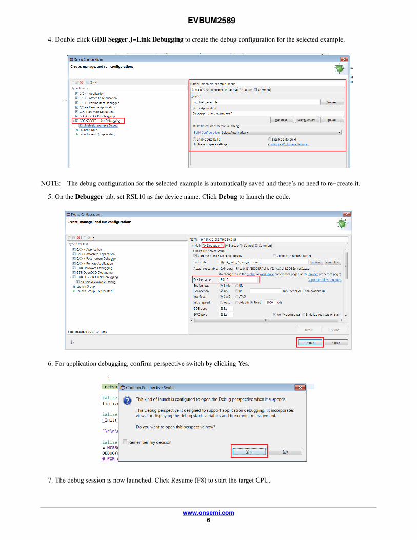
4. Double click GDB Segger J−Link Debugging to create the debug configuration for the selected example.
NOTE: The debug configuration for the selected example is automatically saved and there’s no need to re−create it.
5. On the Debugger tab, set RSL10 as the device name. Click Debug to launch the code.
6. For application debugging, confirm perspective switch by clicking Yes.
7. The debug session is now launched. Click Resume (F8) to start the target CPU.

EVBUM2589
www.onsemi.com7
Compiling and Flashing1. Choose an example (for example, pr_shield_example) to flash by copying it to the workspace.
NOTE: Once the example is copied, it can be viewed under Project Explorer. All source files including main are locatedin the src folder.
EVBUM2589
www.onsemi.com8
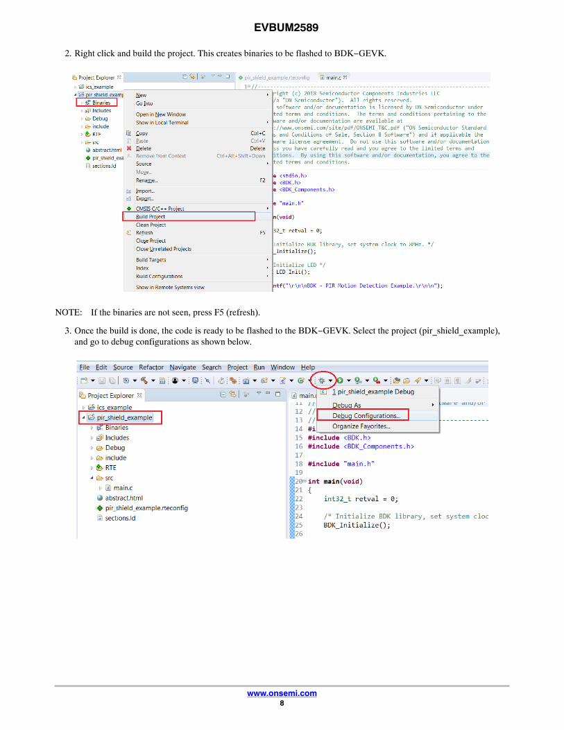
2. Right click and build the project. This creates binaries to be flashed to BDK−GEVK.
NOTE: If the binaries are not seen, press F5 (refresh).
3. Once the build is done, the code is ready to be flashed to the BDK−GEVK. Select the project (pir_shield_example),and go to debug configurations as shown below.

EVBUM2589
www.onsemi.com9
4. Double click GDB Segger J−Link Debugging to create the debug configuration for the selected example.
NOTE: The debug configuration for the selected example is automatically saved and there’s no need to re−create it.
5. On the Debugger tab, set RSL10 as the device name. Click Debug to launch the code.
6. For application debugging, confirm perspective switch by clicking Yes.
EVBUM2589
www.onsemi.com10
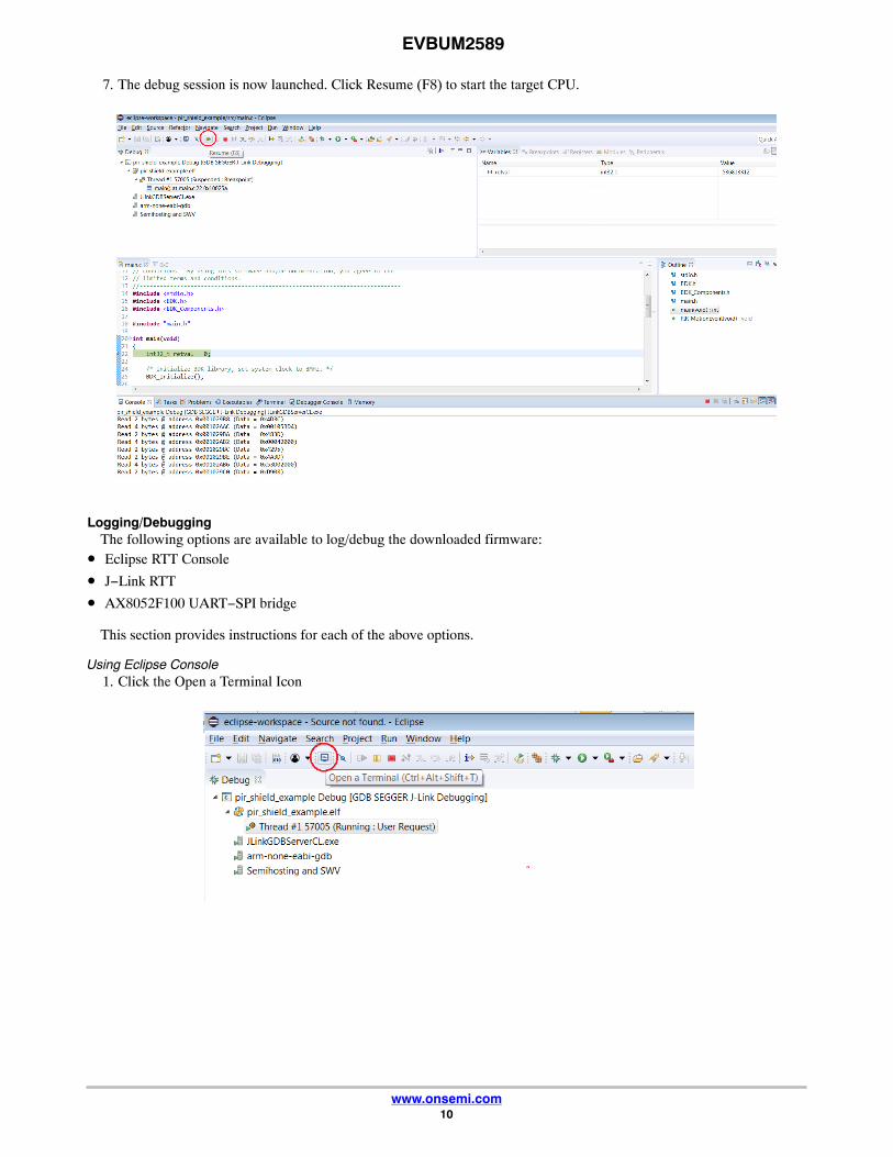
7. The debug session is now launched. Click Resume (F8) to start the target CPU.
Logging/DebuggingThe following options are available to log/debug the downloaded firmware:
• Eclipse RTT Console
• J−Link RTT
• AX8052F100 UART−SPI bridge
This section provides instructions for each of the above options.
Using Eclipse Console1. Click the Open a Terminal Icon

EVBUM2589
www.onsemi.com11
2. Enter the values shown below and launch the session. The incoming events are printed on the terminal window.
EVBUM2589
www.onsemi.com12
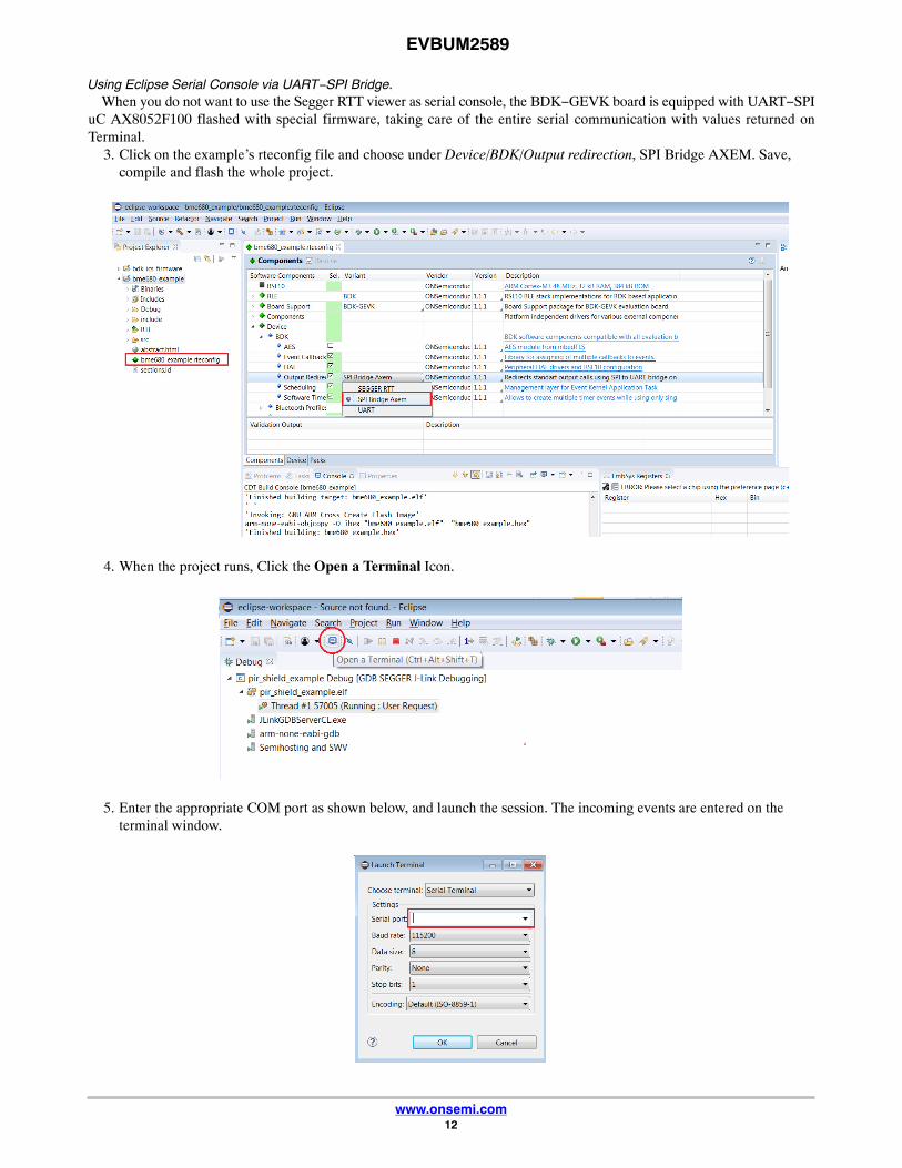
Using Eclipse Serial Console via UART−SPI Bridge.When you do not want to use the Segger RTT viewer as serial console, the BDK−GEVK board is equipped with UART−SPI
uC AX8052F100 flashed with special firmware, taking care of the entire serial communication with values returned onTerminal.
3. Click on the example’s rteconfig file and choose under Device/BDK/Output redirection, SPI Bridge AXEM. Save,compile and flash the whole project.
4. When the project runs, Click the Open a Terminal Icon.
5. Enter the appropriate COM port as shown below, and launch the session. The incoming events are entered on theterminal window.

EVBUM2589
www.onsemi.com13
NOTE: You may reset (PB_RST) the BDK−GEVK (shown below) to launch the RTT terminal without needing to launchEclipse.

EVBUM2589
www.onsemi.com14
Using J−Link RTT6. After step 14 is done, open J−Link RTT viewer (should be installed when J−Link software package was installed per
Step 2).
7. Select USB and click OK.

EVBUM2589
www.onsemi.com15
8. RTT prompts you to select the appropriate microcontroller. Select RSL10 and click OK. The serial terminal is readyto use and the events from RSL10 can be observed by clicking the All Terminals Window.

EVBUM2589
www.onsemi.com16
NOTE: You may reset (PB_RST) the BDK−GEVK (shown below) to launch RTT terminal without needing to launchEclipse.
Using Eclipse Serial Console via UART−SPI BridgeThe BDK−GEVK board is equipped with UART−SPI microcontroller AX8052F100 flashed with special firmware, to enable
serial communication with values returned to Terminal.9. Click on example’s rteconfig file and choose “SPI Bridge AXEM” under Device/BDK/Output redirection.
Save, compile and flash the whole project.
EVBUM2589
www.onsemi.com17
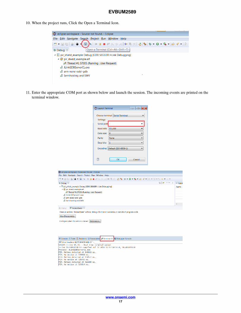
10. When the project runs, Click the Open a Terminal Icon.
11. Enter the appropriate COM port as shown below and launch the session. The incoming events are printed on theterminal window.
EVBUM2589
www.onsemi.com18
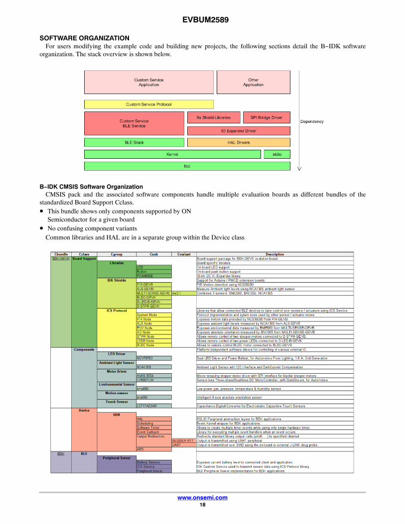
SOFTWARE ORGANIZATIONFor users modifying the example code and building new projects, the following sections detail the B−IDK software
organization. The stack overview is shown below.
B−IDK CMSIS Software OrganizationCMSIS pack and the associated software components handle multiple evaluation boards as different bundles of the
standardized Board Support Cclass.• This bundle shows only components supported by ON
Semiconductor for a given board• No confusing component variants
Common libraries and HAL are in a separate group within the Device class

EVBUM2589
www.onsemi.com19
Board Support
• Libraries to support BDK−GEVK, GPIO Expander, Various daughter cards and custom protocol (required for themobile app)
Components
• Libraries attached to board support
Device
• Abstraction layers for interfaces, timers, AES, serial re−direction, etc.
BLE
• Peripheral Server Support

EVBUM2589
www.onsemi.com20
CONFIGURATION SETUPSystem settings can be configured directly from within the CMSIS pack. Each example is equipped with basic system
configuration that covers three main categories. These are accessible in the RTE/BDK folder within the project. Each systemconfiguration starts with “RTE_”. As shown below, opening the RTE_... header files using the CMSIS configuration wizard(right click on the header file), displays the configuration table. Various application specific parameters can be set. This allowspre−configuration of RSL10 without the need for explicit programming.
A brief description on the header files is given below.

EVBUM2589
www.onsemi.com21
RTE_BDK.hParameters such as system clock frequency and the board that feature RSL10 (default set to BDK−GEVK), etc. can be set.
Descriptions of each of these parameters are also provided.
RTE_Software_Timer.hVarious timers (4) supported by RSL10 can be configured by invoking the CMSIS configuration wizard on this header file.
Timer 1 is used for B−IDK components.
RTE_PCA9655.hPCA9655 is the GPIO expander chip assembled on most daughter cards to expand interface functionality. Parameters related
to this chip can be set here.

EVBUM2589
www.onsemi.com22
RTE_x.hIn addition to configuring system settings, all the supported daughter cards’ parameters can be configured directly using the
configuration wizard, without the need for programming. Once the parameters are changed per the application requirements,saving, rebuilding and flashing the project will let the new parameters take effect. Examples for the stepper and LED ballastdaughter cards are shown below. Other daughter cards can be configured in a similar fashion.
EVBUM2589
www.onsemi.com23
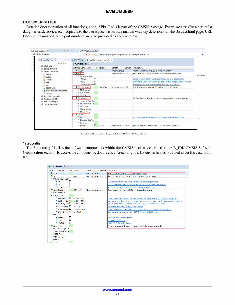
DOCUMENTATIONDetailed documentation of all functions, code, APIs, HALs is part of the CMSIS package. Every use case (for a particular
daughter card, service, etc.) copied into the workspace has its own manual with key description in the abstract.html page. URLInformation and orderable part numbers are also provided as shown below.
*.rteconfigThe *.rteconfig file lists the software components within the CMSIS pack as described in the B_IDK CMSIS Software
Organization section. To access the components, double click *.rteconfig file. Extensive help is provided under the descriptiontab.

EVBUM2589
www.onsemi.com24
Main Help PageThe main help page is accessible via Device/BDK, visible for all use cases in *.rteconfig file. It’s further divided into various
modules as shown below.

EVBUM2589
www.onsemi.com25
Sub−sections may be expanded for further information (Ex: HAL interfaces shown below)
B−IDK also provides software timers and applications task manager abstraction layers to enable management of specifictasks and timing within the event kernel.

EVBUM2589
www.onsemi.com26
Custom Service FirmwareIn order to read sensor data and control actuators connected to the BDK−GEVK from the RSL10 Sense and Control mobile
app, the Custom Service Firmware must be downloaded onto the BDK−GEVK. This firmware can be found as Custom ServiceFirmware under examples in the CMSIS pack.

www.onsemi.com1
onsemi, , and other names, marks, and brands are registered and/or common law trademarks of Semiconductor Components Industries, LLC dba “onsemi” or its affiliatesand/or subsidiaries in the United States and/or other countries. onsemi owns the rights to a number of patents, trademarks, copyrights, trade secrets, and other intellectual property. Alisting of onsemi’s product/patent coverage may be accessed at www.onsemi.com/site/pdf/Patent−Marking.pdf. onsemi is an Equal Opportunity/Affirmative Action Employer. Thisliterature is subject to all applicable copyright laws and is not for resale in any manner.
The evaluation board/kit (research and development board/kit) (hereinafter the “board”) is not a finished product and is not available for sale to consumers. The board is only intendedfor research, development, demonstration and evaluation purposes and will only be used in laboratory/development areas by persons with an engineering/technical training and familiarwith the risks associated with handling electrical/mechanical components, systems and subsystems. This person assumes full responsibility/liability for proper and safe handling. Anyother use, resale or redistribution for any other purpose is strictly prohibited.
THE BOARD IS PROVIDED BY ONSEMI TO YOU “AS IS” AND WITHOUT ANY REPRESENTATIONS OR WARRANTIES WHATSOEVER. WITHOUT LIMITING THE FOREGOING,ONSEMI (AND ITS LICENSORS/SUPPLIERS) HEREBY DISCLAIMS ANY AND ALL REPRESENTATIONS AND WARRANTIES IN RELATION TO THE BOARD, ANYMODIFICATIONS, OR THIS AGREEMENT, WHETHER EXPRESS, IMPLIED, STATUTORY OR OTHERWISE, INCLUDING WITHOUT LIMITATION ANY AND ALLREPRESENTATIONS AND WARRANTIES OF MERCHANTABILITY, FITNESS FOR A PARTICULAR PURPOSE, TITLE, NON−INFRINGEMENT, AND THOSE ARISING FROM ACOURSE OF DEALING, TRADE USAGE, TRADE CUSTOM OR TRADE PRACTICE.
onsemi reserves the right to make changes without further notice to any board.
You are responsible for determining whether the board will be suitable for your intended use or application or will achieve your intended results. Prior to using or distributing any systemsthat have been evaluated, designed or tested using the board, you agree to test and validate your design to confirm the functionality for your application. Any technical, applications ordesign information or advice, quality characterization, reliability data or other services provided by onsemi shall not constitute any representation or warranty by onsemi, and no additionalobligations or liabilities shall arise from onsemi having provided such information or services.
onsemi products including the boards are not designed, intended, or authorized for use in life support systems, or any FDA Class 3 medical devices or medical devices with a similaror equivalent classification in a foreign jurisdiction, or any devices intended for implantation in the human body. You agree to indemnify, defend and hold harmless onsemi, its directors,officers, employees, representatives, agents, subsidiaries, affiliates, distributors, and assigns, against any and all liabilities, losses, costs, damages, judgments, and expenses, arisingout of any claim, demand, investigation, lawsuit, regulatory action or cause of action arising out of or associated with any unauthorized use, even if such claim alleges that onsemi wasnegligent regarding the design or manufacture of any products and/or the board.
This evaluation board/kit does not fall within the scope of the European Union directives regarding electromagnetic compatibility, restricted substances (RoHS), recycling (WEEE), FCC,CE or UL, and may not meet the technical requirements of these or other related directives.
FCC WARNING – This evaluation board/kit is intended for use for engineering development, demonstration, or evaluation purposes only and is not considered by onsemi to be a finishedend product fit for general consumer use. It may generate, use, or radiate radio frequency energy and has not been tested for compliance with the limits of computing devices pursuantto part 15 of FCC rules, which are designed to provide reasonable protection against radio frequency interference. Operation of this equipment may cause interference with radiocommunications, in which case the user shall be responsible, at its expense, to take whatever measures may be required to correct this interference.
onsemi does not convey any license under its patent rights nor the rights of others.
LIMITATIONS OF LIABILITY: onsemi shall not be liable for any special, consequential, incidental, indirect or punitive damages, including, but not limited to the costs of requalification,delay, loss of profits or goodwill, arising out of or in connection with the board, even if onsemi is advised of the possibility of such damages. In no event shall onsemi’s aggregate liabilityfrom any obligation arising out of or in connection with the board, under any theory of liability, exceed the purchase price paid for the board, if any.
The board is provided to you subject to the license and other terms per onsemi’s standard terms and conditions of sale. For more information and documentation, please visitwww.onsemi.com.
PUBLICATION ORDERING INFORMATIONTECHNICAL SUPPORTNorth American Technical Support:Voice Mail: 1 800−282−9855 Toll Free USA/CanadaPhone: 011 421 33 790 2910
LITERATURE FULFILLMENT:Email Requests to: [email protected]
onsemi Website: www.onsemi.com
Europe, Middle East and Africa Technical Support:Phone: 00421 33 790 2910For additional information, please contact your local Sales Representative
◊