evaluation of the u.s. department of energy challenge home ... · wms water management checklist...
TRANSCRIPT

Evaluation of the U.S. Department of Energy Challenge Home Program Certification of Production Builders P. Kerrigan and H. Loomis Building Science Corporation
September 2014

NOTICE
This report was prepared as an account of work sponsored by an agency of the United States government. Neither the United States government nor any agency thereof, nor any of their employees, subcontractors, or affiliated partners makes any warranty, express or implied, or assumes any legal liability or responsibility for the accuracy, completeness, or usefulness of any information, apparatus, product, or process disclosed, or represents that its use would not infringe privately owned rights. Reference herein to any specific commercial product, process, or service by trade name, trademark, manufacturer, or otherwise does not necessarily constitute or imply its endorsement, recommendation, or favoring by the United States government or any agency thereof. The views and opinions of authors expressed herein do not necessarily state or reflect those of the United States government or any agency thereof.
Available electronically at http://www.osti.gov/scitech
Available for a processing fee to U.S. Department of Energy and its contractors, in paper, from:
U.S. Department of Energy Office of Scientific and Technical Information P.O. Box 62 Oak Ridge, TN 37831-0062 phone: 865.576.8401 fax: 865.576.5728 email: mailto:[email protected]
Available for sale to the public, in paper, from:
U.S. Department of Commerce National Technical Information Service 5285 Port Royal Road Springfield, VA 22161 phone: 800.553.6847 fax: 703.605.6900 email: [email protected] online ordering: http://www.ntis.gov/ordering.htm

iii
Evaluation of the U.S. Department of Energy Challenge Home Program Certification of Production Builders
Prepared for:
Building America
Building Technologies Program
Office of Energy Efficiency and Renewable Energy
U.S. Department of Energy
Prepared by:
P. Kerrigan, H. Loomis
Building Science Corporation
30 Forest Street
Somerville, MA 02143
NREL Technical Monitor: Cheryn Metzger
Prepared under Subcontract No. KNDJ-0-40337-04
September 2014

iv
The work presented in this report does not represent performance of any product relative to regulated minimum efficiency requirements. The laboratory and/or field sites used for this work are not certified rating test facilities. The conditions and methods under which products were characterized for this work differ from standard rating conditions, as described. Because the methods and conditions differ, the reported results are not comparable to rated product performance and should only be used to estimate performance under the measured conditions.

v
Contents List of Figures ........................................................................................................................................... vii List of Tables ............................................................................................................................................ viii Definitions ................................................................................................................................................... ix Executive Summary .................................................................................................................................... x 1 Introduction ........................................................................................................................................... 1
1.1 The Purpose of This Research Project ............................................................................................. 1 1.2 Relevance to Building America’s Goals .......................................................................................... 1 1.3 Previous Building America Research With Builders ....................................................................... 2 1.4 U.S. Department of Energy Challenge Home Program ................................................................... 2 1.5 Research Questions .......................................................................................................................... 4
2 U.S. Department of Energy Challenge Home—Home Energy Rating System-Related Upgrades 5 2.1 K. Hovnanian Homes ....................................................................................................................... 5 2.2 David Weekley Homes .................................................................................................................... 7 2.3 Transformations, Inc. ..................................................................................................................... 10
3 Other U.S. Department of Energy Challenge Home Program Requirements ............................... 14 3.1 EPA WaterSense Hot Water Efficiency Distribution .................................................................... 14 3.2 K. Hovnanian Homes ..................................................................................................................... 16 3.3 David Weekley Homes .................................................................................................................. 18 3.4 Transformations, Inc. ..................................................................................................................... 20
3.4.1 Evaluation ......................................................................................................................... 20 3.4.2 Retrofit .............................................................................................................................. 22
3.5 EPA Indoor airPLUS ..................................................................................................................... 23 3.5.1 Section 5.4: Attached Garages .......................................................................................... 23 3.5.2 Section 6: Low-Emission Materials .................................................................................. 24
3.6 K. Hovnanian Homes ..................................................................................................................... 24 3.6.1 Garage Fan ........................................................................................................................ 24 3.6.2 Sump Pit ............................................................................................................................ 24
3.7 David Weekley Homes .................................................................................................................. 25 3.7.1 House-to-Garage Air Leakage .......................................................................................... 25
3.8 Transformations, Inc. ..................................................................................................................... 25 3.8.1 House-to-Garage Air Leakage .......................................................................................... 25 3.8.2 Sump Pit ............................................................................................................................ 26
4 Performance Testing .......................................................................................................................... 28 4.1 K. Hovnanian Homes ..................................................................................................................... 28
4.1.1 House Air Leakage Testing .............................................................................................. 28 4.1.2 Duct Air Leakage Testing ................................................................................................. 29 4.1.3 Individual HVAC Register Flows ..................................................................................... 29 4.1.4 HVAC System Static Pressures ........................................................................................ 30 4.1.5 Bedroom Pressures ........................................................................................................... 30 4.1.6 Point Source Exhaust Airflow .......................................................................................... 30 4.1.7 Hot Water Testing ............................................................................................................. 31
4.2 David Weekley Homes .................................................................................................................. 32 4.3 Transformations, Inc. ..................................................................................................................... 32
4.3.1 Domestic Hot Water System Testing (Water Waste Measurements) ............................... 32 4.3.2 Domestic Hot Water System Testing (Performance Measurements) ............................... 33 4.3.3 House Air Leakage Testing .............................................................................................. 35 4.3.4 House-to-Garage Air Leakage Testing ............................................................................. 35 4.3.5 Ventilation System Testing ............................................................................................... 37
5 Cost Analysis ...................................................................................................................................... 41

vi
5.1 K. Hovnanian Homes ..................................................................................................................... 41 5.1.1 Construction Cost ............................................................................................................. 41 5.1.2 BEopt Energy Modeling ................................................................................................... 42
5.2 David Weekley Homes .................................................................................................................. 43 5.2.1 Construction Cost ............................................................................................................. 43 5.2.2 BEopt Energy Modeling ................................................................................................... 43
5.3 Transformations, Inc. ..................................................................................................................... 45 5.4 Construction Cost .......................................................................................................................... 45
5.4.1 BEopt+ Energy Modeling ................................................................................................. 45 6 Identified Gaps and Barriers ............................................................................................................. 48
6.1 K. Hovnanian Homes ..................................................................................................................... 48 6.2 David Weekley Homes .................................................................................................................. 48 6.3 Transformations, Inc. ..................................................................................................................... 49
7 Conclusions ........................................................................................................................................ 50 7.1 Research Questions ........................................................................................................................ 51
7.1.1 K. Hovnanian Homes ........................................................................................................ 51 7.1.2 David Weekley Homes ..................................................................................................... 52 7.1.3 Transformations, Inc. ........................................................................................................ 53
Appendix .................................................................................................................................................... 56

vii
List of Figures Figure 1. Exhibit 2 prescriptive requirements for Transformations, Inc. .............................................................. 10 Figure 2. Production home (Lot 6) ............................................................................................................................ 11 Figure 3. Custom home (Lot 7) ................................................................................................................................. 11 Figure 4. Internal volume of various water distribution piping (EPA WaterSense) .............................................. 16 Figure 5. K. Hovnanian Plan 601 typical plumbing plan isometric ........................................................................ 17 Figure 6. David Weekley Homes Plan 2878 original plumbing design—second-floor joist ................................. 18 Figure 7. David Weekley Homes Plan 2878 BSC proposed plumbing design—first-floor joist ........................... 19 Figure 8. ¾-in. trunk at basement ceiling ................................................................................................................. 20 Figure 9. Hot and cold ½-in. branches from ¾-in. insulated trunk ........................................................................ 20 Figure 10. DHW piping map for Devens Lot 7 .......................................................................................................... 21 Figure 11. Estimated water volume (gal) stored in DHW piping, by trunk versus branch ................................... 21 Figure 12. First-floor laundry area ............................................................................................................................ 22 Figure 13. Proposed location for D’Mand pump ...................................................................................................... 22 Figure 14. Location of ground fault circuit interrupter receptacle for recirculation pump .................................. 23 Figure 15. Location of Taco D’Mand recirculation pump ....................................................................................... 23 Figure 16. Remote button in second-floor bath ....................................................................................................... 23 Figure 17. Remote button in laundry room .............................................................................................................. 23 Figure 18, Garage fan at K. Hovnanian Plan 601 (grille is covered for protection during construction) ........... 24 Figure 19. Airtight sump cover and air sealed radon pipes at Plan 601 ................................................................ 25 Figure 20. Door closer, Lot 7 ..................................................................................................................................... 25 Figure 21. Hinge pin closure, Lot 6 ........................................................................................................................... 25 Figure 22. Plastic cover of sump pit, Lot 6 .............................................................................................................. 26 Figure 23. Standing water in sump, Lot 6 ................................................................................................................ 26 Figure 24. Plastic cover of sump pit, Lot 7 .............................................................................................................. 26 Figure 25. Dry conditions in sump, Lot 7 ................................................................................................................. 26 Figure 26. Sump pit retrofit cover, Lot 6 .................................................................................................................. 27 Figure 27. Sump pit retrofit cover, Lot 7 .................................................................................................................. 27 Figure 28. Plan 601 front elevation ........................................................................................................................... 28 Figure 29. Plan 601 design register flow versus measured register flow plot ...................................................... 29 Figure 30. Second-floor bath exhaust terminations ................................................................................................ 31 Figure 31. First-floor bath exhaust termination ....................................................................................................... 31 Figure 32. Tester measuring tap water temperature before test ............................................................................ 31 Figure 33. DHW wait time testing (start) .................................................................................................................. 32 Figure 34. DHW wait time testing (end) .................................................................................................................... 32 Figure 35. Water temperature versus time measurements .................................................................................... 34 Figure 36. Navien NR-180 (LP) unit installed in basement ..................................................................................... 34 Figure 37. NREL testing of DHW time versus temperature and “cold slug” risks ............................................... 34 Figure 38. BSC testing of DHW time versus temperature and “cold slug” risks .................................................. 35 Figure 39. Depressurization testing of Lot 7............................................................................................................ 36 Figure 40. Garage pressure tap (Lot 7) .................................................................................................................... 36 Figure 41. Garage-to-house pressure testing at Lot 6 ............................................................................................ 36 Figure 42. Testing bathroom exhaust fan with hood .............................................................................................. 37 Figure 43. Flow measurement at bathroom exhaust ............................................................................................... 37 Figure 44. Fantech SH704 HRV in basement ........................................................................................................... 38 Figure 45. Fantech SH704 HRV in basement ........................................................................................................... 38 Figure 46. Testing bathroom exhaust fan for flow .................................................................................................. 39 Figure 47. No flow at Panasonic fan with switch off ............................................................................................... 39 Figure 48. Light, fan, and wall switches ................................................................................................................... 39 Figure 49. Settings on Panasonic fan (upstairs bath) ............................................................................................. 40 Figure 50. Plan 601 BEopt source energy savings versus the Building America Benchmark— end use
breakdown ........................................................................................................................................................... 42 Figure 51. Plan 601 BEopt optimization graph ........................................................................................................ 43 Figure 53. Plan 2870 BEopt optimization graph ...................................................................................................... 45 Figure 54. Lot 6 BEopt+ optimization results—maximum savings design selected ............................................ 46 Figure 55. Lot 6 BEopt+ optimization results—as-built design selected .............................................................. 47
Unless otherwise noted, all figures were created by Building Science Corporation.

viii
List of Tables Table 1. DOE Challenge Home Verifier (HERS Rater) Duties ................................................................. 3 Table 2. K. Hovnanian Floor Plan Dimensions and Areas ...................................................................... 5 Table 3. Summary of K. Hovnanian Plan 601 Energy Efficiency Package Components ..................... 6 Table 4. Plan 601—Incremental Improvements Impact on HERS Index ................................................ 7 Table 5. David Weekley Homes Floor Plan Dimensions and Areas ....................................................... 7 Table 6. Plan 2870—Incremental Improvements Impact on HERS Index .............................................. 8 Table 7. Summary of David Weekley Homes Energy Efficiency Package Components ..................... 9 Table 8. Transformations, Inc. Floor Plan Dimensions and Areas ...................................................... 11 Table 9. Summary of Transformations, Inc. Energy Efficiency Package Components ..................... 13 Table 10. Pipe Lengths at Lot 6 in Devens ............................................................................................. 20 Table 11. Plan 601 Infiltration Testing Results ...................................................................................... 29 Table 12. Plan 601 Duct Testing Results ................................................................................................ 29 Table 13. Plan 601 HVAC External Static Pressures ............................................................................. 30 Table 14. Plan 601 Room Pressure Measurements ............................................................................... 30 Table 15. Point Source Exhaust System Test Results at Plan 601 ...................................................... 30 Table 16. DHW System Test Results in at K. Hovnanian Plan 601 ...................................................... 32 Table 17. Plan 2870 Infiltration Testing Results .................................................................................... 32 Table 18. DHW System Test Results in Devens ..................................................................................... 33 Table 19.House Air Leakage Test Results in Devens ............................................................................ 35 Table 20. House-to-Garage Air Leakage Test Results in Devens ........................................................ 37 Table 21. Ventilation System Test Results in Devens, Lot 6 ................................................................ 38 Table 22. K. Hovnanian Incremental Construction Costs ..................................................................... 41 Table 23. David Weekley Homes Incremental Construction Costs...................................................... 43 Table 24. Transformations, Inc. DOE Challenge Home Checklist-Related Costs .............................. 45 Table 25. Example Specifications for IECC 2015 Compliance in a Cold Climate ............................... 56
Unless otherwise noted, all tables were created by Building Science Corporation.

ix
Definitions
AFUE Annual Fuel Utilization Efficiency
BEopt™ Building Energy Optimization Software
BSC Building Science Corporation
ccSPF Closed Cell Spray Polyurethane Foam
CFM Cubic Feet per Minute
DOE U.S. Department of Energy
EF Energy Factor
EPA U.S. Environmental Protection agency
HERS Home Energy Rating System
HRV Heat Recovery Ventilator
HSPF Heating Season Performance Factor
HVAC Heating, Ventilation, and Air Conditioning
HVAC/C HVAC System Quality Installation Contractor Checklist
HVAC/R HVAC System Quality Installation Rater Checklist
IECC International Energy Conservation Code
o.c. On Center
ocSPF Open Cell Spray Polyurethane Foam
Pa Pascal
PV Photovoltaic
RERH Renewable Energy Ready Home
SEER Seasonal Energy Efficiency Ratio
SHGC Solar Heat Gain Coefficient
TES Thermal Enclosure Checklist
VOC Volatile Organic Compound
WMS Water Management Checklist
XPS Extruded Polystyrene

x
Executive Summary
The U.S. Department of Energy (DOE) Challenge Home Program is a successor certification program to the DOE Builder’s Challenge Program, a highly successful program that certified more than 14,000 homes since 2008. The DOE Challenge Home represents an improvement over the Builder’s Challenge, not only in energy efficiency but also quality control and sustainability. Below are some basic statistics on the new program.
• Nearly 1,400 homes have already achieved the Challenge Home average performance threshold of a Home Energy Rating System (HERS) 55 under Builders Challenge with nearly 140 zero energy homes achieving a HERS Index score of ‘0’ or lower.
• Nearly 8,000 homes have already committed to DOE Challenge Home certification, mostly by production builders.
• Nearly 80 builders have already committed to 100% Challenge Home construction. The purpose of this project was to evaluate integrated packages of advanced measures in individual test homes to assess their performance with respect to Building America Program goals, specifically compliance with the DOE Challenge Home Program.
To that end, Building Science Corporation (BSC) consulted on the construction of five test houses by three cold climate production builders in three separate U.S. cities.
• K. Hovnanian Homes, Chicago, Illinois
• David Weekley Homes, Denver, Colorado
• Transformations, Inc., Devens, Massachusetts.
Each of the builders in this project has previously expressed interest in evaluating the new DOE Challenge Home, and the possibility of integrating this package into a production environment.
BSC worked with the builders to develop a design package tailored to the cost-related impacts for each builder. Therefore, the resulting design packages do vary from builder to builder.
BSC provided support through this research project on the design, construction, and performance testing of the five test homes.
Overall, the builders have concluded that the energy related upgrades (either through the prescriptive or performance path) represent reasonable upgrades. The builders commented that while not every improvement in specification was cost effective (as in a reasonable payback period), many were improvements that could improve the marketability of the homes and serve to attract more energy efficiency discerning prospective homeowners.
However, the builders did express reservations about the associated checklists and added certifications. An increase in administrative time was observed with all builders. The checklists and certifications also inherently increase cost due to:

xi
• Adding services to the scope of work for various trades, such as HERS Rater and heating, ventilation, and air conditioning contractor.
• Increased material costs related to the checklists, especially the U.S. Environmental Protection Agency Indoor airPLUS and WaterSense Efficient Hot Water Distribution requirement,
The three builders noted that these costs could be reduced as the builder learns more efficient methods of executing the associated checklists, but were unable to provide an accurate quantification of these savings.
In order for any program to succeed, BSC strongly believes that raters will have to serve as effective advocates for the DOE Challenge Program. The three raters BSC worked with in this research project had no previous experience with the DOE Challenge Home Program. In addition to working with the builders on this project, BSC educated each of the raters on the Challenge Home Program. It is expected, that once raters become official DOE Challenge Home verifiers, they will be able to better integrate the program into their services. Cost to the builders, especially costs related to the administrative work, are expected to be reduced once a builder gains experience with the program. These developments, along with the additional exposure and publicity the program will experience, will allow the Challenge Home Program to flourish.
The DOE Challenge Program continues to grow. BSC, along with Building America, advocates for the project and will continue to pursue projects that seek certification.

1
1 Introduction
Building Science Corporation (BSC) consulted with three production builders for this project.
• K. Hovnanian Homes, Chicago, Illinois
• David Weekley Homes, Denver, Colorado
• Transformations, Inc., Devens, Massachusetts.
Each of the builders in this project has previously expressed interest in evaluating the new U.S. Department of Energy (DOE) Challenge Home, and the possibility of integrating this package into a production environment. The floor plans in this project represent a mix of one- and two story houses, all with unfinished conditioned basements. Each project showcases a different enclosure and mechanical design.
1.1 The Purpose of This Research Project Through this advanced new construction energy efficiency packages evaluation, BSC acquired important information about the performance of energy efficient technology packages designed for three production builders. This served to develop the most cost competitive and replicable designs for each builder to meet the DOE Challenge Home program criteria. This work will also assist builders in meeting the upcoming 2015 International Energy Conservation Code (IECC).
Through this work, BSC collected information about:
• Cost and implementation issues with production builders constructing to the DOE Challenge Home program
• Challenges faced by production builders when striving for the DOE Challenge Home program.
1.2 Relevance to Building America’s Goals Overall, the goal of the DOE Building America program is to “reduce home energy use by 30%-50% (compared to 2009 energy codes for new homes and pre-retrofit energy use for existing homes).” To this end, we conduct research to “develop market-ready energy solutions that improve efficiency of new and existing homes in each U.S. climate zone, while increasing comfort, safety, and durability.” 1
The technology package proposed for each of the builders in this pilot project offers a variety of specification alternatives for builders in a cold climate. The information gained through this research about the implementation of the technology package at a production scale serves to inform the greater production builder community across the cold climate region.
The most immediate impact of the research project was to inform the work of each production builder. All five homes were constructed to achieve at least 30% savings versus the Building America Benchmark and will meet the criteria of the DOE Challenge Home program. Lessons
1 http://www1.eere.energy.gov/buildings/building_america/program_goals.html

2
learned both in the economics of the variations in design and constructability can be applied to the future business model of the production builder.
The recent adoption of the new and more stringent 2012 IECC, in some states, is greatly reducing the performance gap between code built homes and those that are constructed to meet an energy efficiency standard (Bailes 2012). The research from this project also has the potential to inform the residential construction industry on the replicability and cost effectiveness of designs that not only meet the current energy code, but will meet future proposed building code improvements, including the anticipated 2015 IECC mandate (which is expected to adopt the Home Energy Rating System [HERS] Index as a performance path metric).
1.3 Previous Building America Research With Builders BSC has been working with production builders around the country since its founding in the mid-1990s. However, this project represents the first collaboration with a builder on achieving DOE Challenge Home certification, as the program was released in 2013.
BSC does have extensive experience working, with builders of all types, on certifying homes under the older DOE Builders Challenge Program. The Builders Challenge Program was a DOE program that was the predecessor to the DOE Challenge Home, and has now been phased out and is no longer available. The Builders Challenge was a more modest energy program, resulting in homes with HERS Index scores in the range of 65–70. It also required a much lower level of quality documentation. BSC was very successful in integrating this program with its builders from 2008 to 2012, resulting in around 100 qualified homes.
1.4 U.S. Department of Energy Challenge Home Program The DOE Challenge Home Program2 is a recently released residential whole-house certification program that is the successor the DOE Builders Challenge Program, which was active from 2008 to 2012. DOE envisions the program as a path toward net-zero energy. That is, the program advocated not only energy efficiency upgrades that result in a high performance house, but also to incorporate upgrades to various systems in order to allow a seamless installation of renewable energy systems should a homeowner wish to achieve net-zero energy status in the future.
The DOE Challenge Home Program can be viewed as being composed of two main categories of criteria:
1. Whole-house performance improvement achieved through energy-related upgrades, either through:
a. Prescriptive path compliance, based on climate zone location
b. Performance path analysis, via a HERS analysis (generally a HERS Index in the mid 50s)
2. A series of required mandates in the form of checklists and guidelines including: a. Compliance with U.S Environmental Protection Agency (EPA) ENERGY STAR®
version 3, including the required checklists:
2 http://www1.eere.energy.gov/buildings/residential/ch_index.html

3
i. Thermal Enclosure System Rater Checklist (TES),
ii. Heating, Ventilation, and Air Conditioning (HVAC) System Quality Installation Contractor Checklist (HVAC/C),
iii. HVAC System Quality Installation Rater Checklist (HVAC/R),
iv. Water Management System Builder Checklist (WMS)
b. U.S. Environmental Protection Agency (EPA) Indoor airPLUS Version 1 Revision 2 Construction Specifications (with DOE Challenge Home-specific exceptions)
c. DOE Challenge Home Program consolidated EPA Renewable Energy Ready Home (RERH) checklist, addressing both solar electric and solar thermal systems.
d. EPA WaterSense New Home Specification – Guide for Efficient Hot Water Delivery Systems.
A DOE Challenge Home is roughly 40%–50% more efficient than a typical new home. This generally corresponds to a HERS Index in the low to mid-50s, depending on the size of the home and the climate zone location (DOE 2013b). This is a higher level of savings compared to the DOE Builders Challenge program, which corresponded to a HERS Index in the mid-60s. However, the required mandates and checklists represent the major addition to the program compared to its predecessor the Builders Challenge.
DOE Challenge Home certification is performed by an accredited verifier, typically a certified HERS rater. A breakdown of the expected duties that a builder can expect of its verifier is shown in Table 1.
Table 1. DOE Challenge Home Verifier (HERS Rater) Duties
Preconstruction
Assess construction plans for program target goals (i.e. REM/Rate analysis)
Provide summary of construction values, products required to meet target. EPA WaterSense - Calculating theoretical water volume in plumbing
runout off of plumbing plans
During Construction
Checklists DOE Challenge Home National Program Requirements (Rev. 03)
ENERGY STAR TES Rater Checklist ENERGY STAR HVAC/R Checklist
ENERGY STAR WMS Builder Checklist EPA WaterSense—visual inspection of plumbing at rough installation
Post-Construction
ENERGY STAR Version 3 Testing and Commissioning Whole-house infiltration test
Duct leakage test Bedroom pressure difference test with door closed
Individual HVAC register airflows Outside airflow
Point source exhaust fan airflow

4
Other Certification Testing and Commissioning EPA WaterSense—hot water delivery test
EPA Indoor airPLUS—attached garage to house pressure test Certification Documentation
Compile all checklists and keep records on file Register and issue DOE Challenge Home Certificate and Label
Notes on checklists:
• The ENERGY STAR HVAC System Quality Contractor Checklist is completed and verified by the HVAC installer and builder.
• The DOE Challenge Home Program consolidated EPA RERH checklist is verified by the builder.
1.5 Research Questions BSC sought to answer the following research questions through this Building America project:
1. What is the most cost-effective, best performing, and most easily replicable method of achieving compliance with the DOE Challenge Home program?
2. What are the challenges that builders face when integrating the DOE Challenge Home into a production environment?
3. Do production builders view DOE Challenge Home as a program that can result in homes that are competitive and affordable in the marketplace?

5
2 U.S. Department of Energy Challenge Home—Home Energy Rating System-Related Upgrades
Two of the builders chose the performance path for meeting the DOE Challenge Home criteria. This allowed each builder to tailor the energy related upgrades to suit their specific abilities and preferences. It should be noted that each builder chose to consider certain upgrades over others; therefore a full parametric analysis of all available upgrades to a residential buildings was not performed. Rather, a limited parametric analysis was performed on each building, taking into account elements that each builder was willing to consider upgrading. Each builder has its own preferences, experiences, material availability, and faith in a particular contractor’s ability to properly implement a specific energy related upgrade.
One builder (Transformations, Inc.) certified two homes via the prescriptive path, and ensured that the specifications of the homes met or exceeded those stipulated in Exhibit 2 of the Requirements.
The individual sections below discuss the energy-related upgrades and DOE Challenge Home certification path details. A discussion on the DOE Challenge Home required checklists and third party certifications are in Section 3.
2.1 K. Hovnanian Homes K. Hovnanian homes constructed one DOE Challenge Home Program-certified home for this project. The house is a two-story building with a conditioned unfinished basement.
Table 2 lists the dimensions and areas for the DOE Challenge Home-certified house (Floor Plan 601).
Table 2. K. Hovnanian Floor Plan Dimensions and Areas
Floor Plan
# Floors
Floor Area (ft2)
Surface Area (ft2)
Volume (ft3) # Beds # Baths Glazing
Ratio 601 2 3,202 5,492 29,286 3 2.5 10.6%
The house was certified through the DOE Challenge Home performance path. BSC held an initial onsite meeting in July 2013 to discuss the DOE Challenge Home program energy-related upgrades that K. Hovnanian preferred to consider. The builder sought to achieve DOE Challenge home compliance through improvements that were the easiest to integrate into a “quick build” scenario.
Table 3 shows the final building specifications for the Plan 601.

6
Table 3. Summary of K. Hovnanian Plan 601 Energy Efficiency Package Components
Enclosure Specifications
Roof Description Medium color asphalt shingles on truss roof – vented attic Insulation R-49 blown fiberglass, grade I
Walls Description 2 × 4 @ 16 in. o.c. with insulating sheathing
Insulation R-13 fiberglass batts with R-5 1-in. extruded polystyrene (XPS) insulating sheathing, grade I
Foundation Description Conditioned basement Insulation R-19 vinyl faced fiberglass batts draped full height, grade I
Windows Description Above grade: ENERGY STAR-certified double-pane vinyl-framed with low-e
Below grade: Non-ENERGY STAR-certified double-pane vinyl-framed with low-e U-value Above grade: U = 0.29; below grade: U = 0.39
Solar heat gain coefficient (SHGC) Above grade: SHGC = 0.28; below grade: SHGC = 0.24
Infiltration Specification 0.25 CFM 50/ft2 enclosure @ 50 Pa Performance test Test result = 0.12 CFM 50/sf enclosure @ 50 Pa
Mechanical Specifications
Heating Description 95% annual fuel utilization efficiency (AFUE) sealed combustion condensing natural gas furnace in conditioned basement
Cooling Manufacturer and Model Goodman GMH950703BXAF Description 13 seasonal energy efficiency ratio (SEER) single-stage air conditioner
Domestic Hot Water (DHW)
Manufacturer and Model Goodman GSX130301BC Description 50-gal sealed combustion condensing tank gas water heater (energy factor [EF] = 0.96)
Distribution Manufacturer and Model AO Smith Vertex 00
Description Metal duct system 100% in conditioned space via the floor joist system Leakage Maximum 5% duct leakage to outside
Ventilation Description
Central fan integrated supply system with 6-in. insulated outside air duct and motorized damper
Duty cycle: 10 min on; 20 min off, 50 CFM average flow; ASHRAE 62.2-2010 compliance achieved via ASHRAE 62.2 compliant bath fan
Manufacturer and Model Fan controller: Air Cycler FRV/VS fan cycler with motorized damper Bath exhaust fan: Panasonic FV-08VQ5 WhisperCeiling
Return Pathways Description Jump ducts to bedrooms

7
Table 4 lists the energy-related upgrades that the builder chose to pursue and the incremental impact on the HERS Index as well at DOE Challenge Home (CH), ENERGY STAR Version 3 (ES V3) and IECC 2012 qualified status.
Table 4. Plan 601—Incremental Improvements Impact on HERS Index
HERS Index CH ES
V3 IECC 2012
Standard K. Hovnanian-Chicago Construction 64 NO NO NO 1-in. XPS Insulating Sheathing 62 NO NO NO
ENERGY STAR Windows (U = ~0.30, SHGC = ~0.28) 60 NO NO NO
3.0 ACH 50 to 1.7 ACH 50 (Measured Result) 57 NO YES NO Upgrade furnace from 92.1% to 95% AFUE 56 NO YES YES Upgrade Water Heater From 0.60 to 0.96 EF 49 NO YES YES
Upgrade Compact Fluorescent Lamps From 75% to 80% of Total Fixtures 48 NO YES YES
ENERGY STAR-Certified Appliances 45 YES YES YES 2.2 David Weekley Homes David Weekley Homes constructed two DOE Challenge Home Program-certified homes for this project. Both homes are two-story residences with conditioned basements.
Table 5 lists the dimensions and areas for both floor plans. A mix of one- and two-story floor plans can be observed.
Table 5. David Weekley Homes Floor Plan Dimensions and Areas
Floor Plan
# Floors
Floor Area (ft2)
Surface Area (ft2)
Volume (ft3)
# Beds
# Baths
Glazing Ratio
2870 2 1593 5529 22514 3 2.5 19.7% 2878 2 2430 7667 35383 3 2.5 19.7%
The house was certified through the DOE Challenge Home Performance Path. As with K. Hovnanian, David Weekley Homes sought to achieve DOE Challenge homes compliance through improvements that were the easiest to integrate into a “quick build” scenario, and to minimize overall specification changes.
Table 6 lists the energy-related upgrades that the builder chose to pursue and the incremental impact on the HERS Index as well at DOE Challenge Home (CH), ENERGY STAR Version 3 (ES V3) and IECC 2012 qualified status.
Table 7 shows the final building specifications for both houses.

8
Table 6. Plan 2870—Incremental Improvements Impact on HERS Index
HERS Index CH ES V3 IECC 2012 Standard David Weekley-Denver Construction 62 NO NO NO
1-in. XPS Under Slab 61 NO NO NO R-49 Ceiling Insulation 60 NO NO NO
3.0 ACH 50 to 2.4 ACH 50 (Measured Result) 58 NO YES NO Upgrade Furnace From 92.1% to 98% AFUE 56 NO YES YES
Upgrade Cooling From 13 to 20 SEER 54 NO YES YES ENERGY STAR-Certified Appliances 50 YES YES YES

9
Table 7. Summary of David Weekley Homes Energy Efficiency Package Components
Enclosure Specifications
Roof Description Medium color asphalt shingles on truss roof – vented attic Insulation R-49 blown fiberglass, grade I
Walls Description 2 × 6 @ 24-in. o.c. Insulation R-23 blown fiberglass, Grade I
Foundation Description Conditioned basement Insulation R-19 vinyl faced fiberglass batts draped full height, Grade I
Windows Description Above grade: ENERGY STAR-certified double-pane vinyl-framed with low-e
Below grade: Non-ENERGY STAR-certified double-pane vinyl-framed with low-e U-value Above grade: U = 0.30; below grade: U = 0.30 SHGC Above grade: SHGC = 0.35; below grade: SHGC = 0.30
Infiltration Specification 0.25 CFM 50/ft2 enclosure @ 50 Pa Performance test Test Result = 0.25 CFM 50/ft2 enclosure @ 50 Pa
Mechanical Specifications
Heating Description 98% AFUE sealed combustion condensing natural gas furnace in conditioned basement Manufacturer and Model Lennox SLP98V
Cooling Description 20 SEER two-stage air conditioner Manufacturer and Model Lennox XC25
DHW Description Tankless gas water heater (EF = 0.82) Manufacturer and Model Rinnai R75i
Distribution Description Metal duct system 100% in conditioned space via the floor joist system Leakage Maximum 5% duct leakage to outside
Ventilation Description
Central fan integrated supply system with 6-in. insulated outside air duct and motorized damper Duty Cycle: 10 minutes on; 20 minutes off, 50 CFM average flow;
ASHRAE 62.2-2010 compliance achieved via ASHRAE 62.2-compliant bath fan
Manufacturer and Model Fan controller: Air Cycler FRV/VS fan cycler with motorized damper Bath exhaust fan: Panasonic FV-08VF2 WhisperFit
Return Pathways Description Jump ducts to bedrooms

10
2.3 Transformations, Inc. Transformations, Inc. selected two homes located in the Devens Sustainable Housing development in Devens, Massachusetts to be submitted for the DOE Challenge Home Program: Lot 6 (Saltbox) and Lot 7 (Custom Saltbox). The homes were completed in 2012 and have been occupied for more than a year.
The homes obtained certification through the prescriptive path. Both houses qualified to use this option by meeting the conditioned floor area for the Benchmark Home requirements set by the program—the program guidelines specify the conditioned floor area for a three-bedroom home cannot exceed 2,200 ft2—as well as mandatory requirements for all labeled homes (Exhibit 1) and the prescriptive specifications of the DOE Challenge Home Target Home for Climate Zone 5 (Exhibit 2).
The houses were also required to meet or exceed the specifications in Exhibit 2 (Figure 1).
Figure 1. Exhibit 2 prescriptive requirements for Transformations, Inc.
The homes were exempt from completing both the EPA RERH Solar Photovoltaic and Solar Thermal Specification Checklists. The program specifies that if the photovoltaic (PV) or solar thermal systems were already in place, the compliance with the checklists is not required. Another condition specified by the program states that the homes have at least 5 kWh/m2/day

11
average daily solar radiation. Based on the location of the homes, and as calculated by the PVWatts, the homes have an average daily solar radiation of 4.31 kWh/m2/day. The PV systems were installed in the homes as part of the original house packages and the solar thermal systems were not installed at all.
The homes met most of the requirements in the remaining mandatory checklists; however, there were a number of items that needed to be retrofitted in order to qualify for the certification. See Sections 3 and 4 of the report for the description of retrofit measures.
Once the necessary items were addressed, the documentation was sent it to obtain the certification and the homes were entered into the DOE Challenge Home Builder Awards. Both were selected as winners in the Production Home and Custom Home categories.
Figure 2. Production home (Lot 6)
Figure 3. Custom home (Lot 7)
The Lot 6 house features the developer’s standard Saltbox floor plan with three bedrooms, two and a half bathrooms, living room, dining room, kitchen, a basement, and a two-car garage. The Lot 7 house features a custom Saltbox floor plan with three bedrooms, two bathrooms, living room, dining room, kitchen, a laundry room, a screened in porch, a basement and a two-car garage.
Table 8. Transformations, Inc. Floor Plan Dimensions and Areas
Floor Plan
# Floors
Floor Area (ft2)
Surface Area (ft2)
Volume (ft3)
# Beds
# Baths
Glazing Ratio
Lot 6 2 1,500 4,508 20,721 3 2.5 13.8% Lot 7 2 1,952 5,292 26,142 3 2.0 12.7%
Over the years, Transformations, Inc. has developed a specific set of assemblies and specifications that are being used for the homes it currently builds. The enclosure characteristics in the Devens homes include full basements with 2 in. of XPS rigid insulation (R-10) under the slab; 3½ in. of closed cell spray polyurethane foam (ccSPF) (2.0/ft3) insulation (R-20) at the basement walls finished with gypsum board; a double-stud wood framed above-grade wall with 12 in. of open cell spray polyrurethane foam (ocSPF) (0.5/ft3) insulation (R-45 nominal);

12
ENERGY STAR-qualified windows (R-5); 20 in. of cellulose insulation at the attic floor (R-70) and 2 in. of ccSPF with 12 in. of cellulose insulation at the sloped roof (R-54 nominal). The mechanical system consists of two single-head mini-split units: one head per floor, a ventilation system (chosen by the homeowner), as well as a tankless propane water heater. A PV array is also included in the house package—16.31 kW on Lot 6 and 17.28 kW on Lot 7. With the PV systems in place the houses achieved HERS –37 (Lot 6) and –21 (Lot 7). Without the PV system the HERS score for Lot 6 was 35 and for Lot 7 the score was 34.
Table 9 includes a summary of the specifications for each building component with the manufacturers listed for all products.

13
Table 9. Summary of Transformations, Inc. Energy Efficiency Package Components
COMPONENT SPECIFICATIONS ENCLOSURE
Roof Description Medium color asphalt shingles – vented and unvented attic Insulation R-60 and R-70 blown cellulose, grade I Insulation R-54 ccSPF and blown cellulose, grade I
Walls Description Double-stud wall, 2 × 4 @ 16 in. o.c. Insulation R-45 ocSPF, grade I
Foundation Description Conditioned basement Insulation R-20 ccSPF, Grade I with gypsum board as thermal barrier
Windows Description Above grade: Harvey Tribute double-hung ENERGY STAR-certified
triple-pane vinyl-framed with low-e U-value Above grade: U = 0.20 SHGC Above grade: SHGC = 0.22
Infiltration Specification 0.25 CFM 50/ft2 enclosure @ 50 Pa Performance test Test Result = 0.09 CFM 50/ft2 enclosure @ 50 Pa
MECHANICAL
Heating Description 10.6 heating season performance factor (HSPF) ductless mini-split air source heat pump (one head per floor)
Manufacturer and Model Mitsubishi Hyper Heat; MSZ-FE12NA/MUZ-FE12NA
Cooling Description 23 SEER Ductless mini-split air source heat pump (one head per floor) Manufacturer and Model Mitsubishi Hyper Heat MSZ-FE12NA/MUZ-FE12NA
DHW Description Condensing propane tankless water heater (EF = 0.96) Manufacturer and Model Navien NR-180-NG
Ventilation
Description Heat recovery ventilator (HRV) ASHRAE 62.2-2010 compliance achieved via HRV
Manufacturer and Model HRV: Fantech SH704
Bath exhaust fan: ENERGY STAR-certified Panasonic FV-08VKS WhisperGreen
Description ASHRAE 62.2-2010 compliance achieved via ASHRAE 62.2-compliant bath fan
Manufacturer and Model Bath exhaust fan: Panasonic FV-08VKS WhisperGreen

14
3 Other U.S. Department of Energy Challenge Home Program Requirements
The mandatory requirement (Exhibit 1) for the DOE Challenge Program refers to a number of third-party certification programs, codes, and checklists:
• EPA ENERGY STAR for Homes Version 3 checklists:
o TES Rater Checklist
o HVAC/C Checklist
o HVAC/R Checklist
o WMS Builder Checklist
• EPA Indoor airPLUS Construction Specifications (with DOE Challenge Home-specific exceptions)
• DOE Challenge Home consolidated EPA RERH checklist, addressing both solar electric and solar thermal systems
• EPA WaterSense New Home Specification – Guide for Efficient Hot Water Delivery Systems.
Copies of the specific checklists can be found in the appendix.
3.1 EPA WaterSense Hot Water Efficiency Distribution The DOE Challenge Home National Program Requirements (Rev. 03) mandates that all labeled homes shall have hot water delivery systems that meet an efficiency requirement. The hot water delivery system shall comply with Section 3.3 of the EPA WaterSense Single Family New Home Specification Version 1.1. Footnote 14 from the requirements document states the following design criteria:
Hot Water Delivery System – To minimize water wasted while waiting for hot water, the hot water distribution system shall store no more than 0.5 gallons (1.9 liters) of water in any piping/manifold between the hot water source and any hot water fixture. In the case of occupant-controlled or occupancy sensor-based recirculation systems, the 0.5 gallon (1.9 liter) storage limit shall be measured from the point where the branch feeding the fixture branches off the recirculation loop, to the fixture itself. To verify that the system stores no more than 0.5 gallons (1.9 liters), verifiers shall calculate the stored volume using the piping or tubing inside diameter and the length of the piping/tubing.
In addition to section 3.3 of the EPA WaterSense Single Family New Home Specification Version 1.1, there is a companion EPA WaterSense document titled “Guide for Efficient Hot Water Delivery Systems.” The guide is designed to assist designers, architects, and builders to better understand the criteria in more detail. It also provides recommended design considerations for efficient hot water distribution systems.

15
As stated in the “Guide for Efficient Hot Water Delivery Systems” document, there are typically four basic hot water delivery system types:
• Trunk and branch systems
• Core systems
• Whole-house manifold systems
• Demand-initiated recirculation systems.
Each hot water delivery system type has its advantages and disadvantages. A production builder must take into consideration a variety of factors when determining how to upgrade the hot water delivery system for a certain residence.
In addition the footnotes also specify a performance criterion:
To account for the additional water that must be removed from the system before hot water can be delivered, no more than 0.6 gallons (2.3 liters) of water shall be collected from the hot water fixture before hot water is delivered. Recirculation systems must be based on an occupant-controlled switch or an occupancy sensor. Recirculation systems that are activated based solely on a timer and/or temperature sensor do not meet this requirement. To verify that the system meets the 0.6 gallon (2.3 liter) limit, verifiers shall first initiate operation of occupant-controlled or occupancy sensor-based recirculation systems, if present, and let such systems run for at least 40 seconds. Next, a bucket or flow measuring bag (pre-marked for 0.6 gallons) shall be placed under the hot water fixture. The hot water shall be turned on completely, a digital thermometer placed in the stream of water just where it meets the water being collected, and the starting temperature recorded. Once the water reaches the pre-marked line (approximately 24 seconds for a lavatory faucet), the water shall be turned off and the ending temperature reading at the same location recorded. The temperature must increase by 10 °F. Only the fixture with the greatest stored volume between the fixture and the hot water source (or recirculation loop) needs to be tested.
This test is to be performed by the rater during the commissioning of the house. This protocol is representative of the additional testing required for the DOE Challenge Home Program, compared to its predecessor DOE Builders Challenge.
A discussion on the hot water distribution design for each of the builder partners is detailed in the sections below.
The volume of the water in the pipes can be estimated based on the pipe diameter and lengths. Pipe volumes are shown in Figure 4, which is taken from the EPA WaterSense document “Guide for Efficient Hot Water Delivery Systems” (EPA 2013b).

16
Figure 4. Internal volume of various water distribution piping (EPA WaterSense)
3.2 K. Hovnanian Homes The typical plumbing design for K. Hovnanian, in Chicago, Illinois, is a standard trunk and branch system. Figure 5 shows the typical plumbing plan for Plan 601. As drawn, many of the plumbing lengths were resulting in volumes exceeding the 0.5 gallon (64 ounce) limit, as stipulated by the EPA WaterSense. Two main factors were contributing to increased water volume in the initial plumbing layout:
• The water heater was originally located in the basement, resulting in very long runs to the second floor.
• Most of the branches were called out as ¾-in. pipe.
• The specified plumbing material was CPVC Schedule 40, which has a larger interior diameter compared to other plumbing material options.

17
Figure 5. K. Hovnanian Plan 601 typical plumbing plan isometric
BSC discussed the WaterSense specifications with the builder and proposed a design with the following major design changes:
1. Move the water heater to the utility closed on the second floor. This floor plan does not have a hot water fixture in the basement, therefore moving the water heater to the living space resulted in shorter runs to the fixtures.
2. Change the plumbing material to CPVC CTS SDR 11, which exhibits smaller interior diameter. This increased the allowable length by 33%.
3. Many of the individual branches were reduced in size from ¾ in. to ½ in., which almost doubles the allowable length of those branches.
An isometric plumbing schematic is not available for the BSC proposed design; however, a plumbing layout sketch is available in the appendix.

18
3.3 David Weekley Homes David Weekley Homes, in Denver, hired a plumbing design firm to provide a plumbing plan that meets the EPA WaterSense specifications. The design firm chose to utilize a recirculation loop to meet the mandate and first created a plumbing layout for plan 2878. The original design can be found in the appendix. The plumbing material that was specified was PEX CTS SDR 9, which has the smallest interior diameter compared to most residential plumbing materials. The recirculation loop for this design starts at the front of the house in the first floor joist and extends up into the second floor joist cavity to the rear of the house. It also included a mini manifold system in the second floor joist to service the upstairs bath fixtures. The original design did meet the WaterSense specification; however BSC did choose to provide an alternative design. The original design specified branch lengths that were of varying lengths between fixtures. This could lead to performance differences between individual fixtures (i.e. Powder room sink takes more time to deliver hot water compared to the bath sink). Figure 6 shows the plumbing layout in the second floor joist system. The orange line indicates the return of the recirculation loop and the mini manifold system can be seen above the kitchen.
Figure 6. David Weekley Homes Plan 2878 original plumbing design—second-floor joist

19
BSC provided a different design that sought to keep the branch length short, and of an equidistant length as compared to each fixture. This involved the lengthening and relocating of the recirculation loop, such that branch lengths could be minimized. Figure 7 shows the location of the recirculation loop, in green, in the first floor joist. The recirculation loop is routed as close to each of the fixtures as possible. There are risers that lead to the second floor joist system on the right hand side of the plan. The proposed plan did not specify a manifold system in the second floor joist system, but rather placed the second-floor recirculation loop directly below most of the fixtures and specified very short branch lengths. BSC performed a takeoff of each designs and calculated a rudimentary cost analysis. While the BSC proposed recirculation loop was 58 ft longer, the branch lengths were reduced by 128 ft. This overall reduction in material, plus the elimination of the mini manifold systems, resulted in what BSC believes to be a cheaper design. The full BSC proposed plumbing layout can be found in the appendix. David Weekley Homes decided to use the BSC plumbing design for the two homes.
Figure 7. David Weekley Homes Plan 2878 BSC proposed plumbing design—first-floor joist

20
3.4 Transformations, Inc. 3.4.1 Evaluation The DHW system in the Devens houses is a single trunk and branch system, plumbed with flexible PEX piping. There is a ¾-in. trunk line running the length of the house (Figure 8), with ½-in. branches off of the trunk, to fixtures (Figure 9). The hot water trunk is insulated (with some missing insulation portions); the branches are uninsulated.
Figure 8. ¾-in. trunk at basement
ceiling
Figure 9. Hot and cold ½-in. branches from
¾-in. insulated trunk
The pipe lengths for Lot 7 were mapped where visible in the basement, and the hidden runs were estimated, as shown in Figure 10. These lengths were tabulated, and estimated volumes of stored water were calculated, as shown in Table 10, and in the graph in Figure 11. The figures highlighted in red represent values that exceed the requirement of the program—0.5 gallon.
Table 10. Pipe Lengths at Lot 6 in Devens
Fixture Trunk Length
(linear ft)
Trunk Volume
(gal)
Branch Length
(linear ft)
Branch Volume
(gal)
Total Volume
(gal) Kitchen 6.0 0.1 15 0.1 0.3
Second-Floor Bathtub 24.5 0.5 12 0.1 0.6 First-Floor Shower 40.5 0.8 12 0.1 0.9
First-Floor Lavatory Sink 2 42.5 0.8 3 0.0 0.8 First-Floor Lavatory Sink 1 43.3 0.8 2 0.0 0.8
Laundry (Washer) 50.3 0.9 5 0.0 1.0

21
Figure 10. DHW piping map for Devens Lot 7
Based on the graph of stored water (Figure 11), it is clear that the majority of the stored water is in the ¾-in. trunk line, especially at the locations further from the water heater. In addition, most of the fixtures exceed the 0.5-gallon maximum storage volume required by the Challenge Home Program.
Figure 11. Estimated water volume (gal) stored in DHW piping, by trunk versus branch
0.0 0.2 0.4 0.6 0.8 1.0 1.2
Kitchen
Second Floor Bathtub
First Floor Shower
First Floor Lav Sink 2
First Floor Lav Sink 1
Laundry (washer)
Stored Water Volume (Gallons)
Trunk Volume (gallons)Branch Volume (gallons)
0.5 gal max for Challenge Home

22
3.4.2 Retrofit Prior to the deadline for submitting the applications for the DOE Challenge Home Builder Awards set for August 1, 2013, DOE had announced that the requirement for meeting the EPA WaterSense checklist was being waived for this year’s applicants. The owner of the Lot 7 house decided to move forward with the retrofit of the system; however, the owner of Lot 6 declined.
For the retrofit of the unit, BSC recommended using the Taco D’Mand demand-based recirculation pump system, Model 008-DM-PK. This particular model is designed for a tankless water heater unit sized for a “small/medium” house.
The fact that the trunk holds the majority of the stored water is an advantage when retrofitting a demand recirculation pump. The pump fills the entire ¾-in. trunk with hot water, which is the majority of the stored/wasted water for most fixtures. The branch volume’s water, in comparison, is a small amount, although it is noticeably larger for longer branch lines, such as second-floor runs, or the shower away from the trunk line.
Based on the geometry of the plumbing system at Lot 7, the laundry area is located at the end of the ¾-in. trunk run (Figure 12); the end of the trunk is the ideal location for the recirculation pump, as it will “flush out” the entire length of the trunk. The pump will create a cross-connection between end of hot water “trunk line” and cold water “trunk line.”
The laundry appliances are located on the first floor (Figure 12); however, the laundry feeds are at the end of the trunk in the basement. Therefore, BSC recommended that the D’Mand pump was installed in the basement, connected to the PEX lines accessible from the basement (Figure 13; shown as a conceptual installation).
Figure 12. First-floor laundry area
Figure 13. Proposed location for D’Mand pump
A ground fault circuit interrupter duplex electrical receptacle for powering the pump was installed on the side of the joist, as noted by the outlet symbol in Figure 13, and shown in Figure 14. The pump was installed in one joist bay area away from the receptacle with the RF Remote Transmitter/Receiver Kit connected to the pump (Figure 15). The RF individual remote transmitter buttons were placed at the remotes sinks, in the first-floor master and the second-floor bathrooms as well as the laundry room (Figure 16 and Figure 17).

23
Figure 14. Location of ground fault circuit
interrupter receptacle for recirculation pump
Figure 15. Location of Taco D’Mand
recirculation pump
Figure 16. Remote button in second-floor bath
Figure 17. Remote button in laundry room
3.5 EPA Indoor airPLUS The Indoor airPLUS specifications feature a comprehensive set of indoor air quality-related improvements. Two sections of the specifications, which most impacted the design and construction of the homes, are discussed below.
3.5.1 Section 5.4: Attached Garages A feature that generated a strong reaction from our builder partners was the requirement for an exhaust fan to be installed in attached garages along with an automatic door closer at the garage door to the living space. An exhaust fan with a minimum installed capacity of 70 CFM is to be installed in the attached garage. The fan either can be operated continuously, or automated controls can be included that can sense garage occupation and operate the fan operate the fan accordingly. Most of BSC’s builder partners offered strong negative reactions to this specification, citing additional cost and procurement complexities for a system that was viewed as unnecessary.

24
BSC was informed by EPA, during this research project, that an exemption to the required garage fan was being considered. This was in response to negative feedback from some builders regarding the fan and controls requirement. EPA updated the Indoor airPLUS Specifications (from version 01, revision 01 to version 01, revision 02) in November 2013. Per the specification, an additional test would be required to measure garage air leakage with respect to the house; with the intent of determining how well isolated the attached garage is from the living space (Rudd 2013).
Verify that the garage-to-house air barrier can maintain a pressure difference of greater than 45 Pascals while the home maintains a 50 Pascal pressure difference with respect to the outdoors. All operable garage openings shall be closed during this test.
3.5.2 Section 6: Low-Emission Materials The specifications in this section proved to be the most difficult to satisfy. Section 6 specifies that wood products, interior paints and carpet materials must be certified as low VOC (volatile organic compounds) emission materials. An extensive list of various emission requirements and certification programs are listed for these materials. The builders had difficulty procuring the certification status of their materials, plus difficulty in finding materials that met the standards. Consequently, builder feedback was skeptical as to the applicability of these specifications, especially at a competitive cost.
3.6 K. Hovnanian Homes 3.6.1 Garage Fan K. Hovnanian elected to install an exhaust fan in the garage, see Figure 18.
Figure 18, Garage fan at K. Hovnanian Plan 601
(grille is covered for protection during construction)
3.6.2 Sump Pit Section 2.1 of the Indoor airPLUS requirements states that an airtight sump pump cover shall be installed to prevent the introduction of soil gases (from the sump) and moisture into the basement. Figure 19 shows a picture of the installed sump cover.

25
Figure 19. Airtight sump cover and air sealed radon pipes at Plan 601
3.7 David Weekley Homes 3.7.1 House-to-Garage Air Leakage The builder opted to pursue exemption of the garage fan. To meet the revised requirement of EPA Indoor airPLUS for the house-to-garage air leakage, a house was tested and passed. See Section 4 for a detailed description of the testing procedure.
3.8 Transformations, Inc. 3.8.1 House-to-Garage Air Leakage To meet the revised requirement of EPA Indoor airPLUS for the house-to-garage air leakage, both houses were tested with depressurization testing and passed. See Section 4 for a detailed description of the testing procedure.
The doors from the house to the garage in both homes were already equipped with weather stripping but lacked the door closers. In Lot 7, a door closer was installed at the garage door connected to the back hallway (Figure 20). In Lot 6, the garage door is located off the living room and the owner was concerned about the appearance of the door closer. Therefore, to meet the requirement of the program, a hinge pin closure was installed instead (Figure 21).
Figure 20. Door closer, Lot 7
Figure 21. Hinge pin closure, Lot 6

26
3.8.2 Sump Pit The sump pit in Lot 6 had a plastic cover with an open slot from the sump to the basement, as shown in Figure 22. There was standing water in the sump pit, roughly 18 in. below floor level (Figure 23).
Figure 22. Plastic cover of sump pit, Lot 6
Figure 23. Standing water in sump, Lot 6
Lot 7 had a similar sump pit cover (Figure 24) but had dry conditions inside it (Figure 25).
Figure 24. Plastic cover of sump pit, Lot 7
Figure 25. Dry conditions in sump, Lot 7
The sump cover that was used for retrofitting the existing installation was Jackel, Inc.’s Original Radon/Sump Dome, which bolts down to concrete floor with concrete screws, and is caulked to existing floor. The access panel of this cover can be opened without breaking the caulk seal to the slab.

27
Figure 26. Sump pit retrofit cover, Lot 6
Figure 27. Sump pit retrofit cover, Lot 7

28
4 Performance Testing
The DOE Challenge Home program requires the following performance testing as part of the verification procedure under the ENERGY STAR version 3 checklists (DOE 2013a):
• Blower door test to measure the house infiltration rate, using the depressurization method ASTM E779 with computerized multipoint measurements (ASTM 2003a)
• Duct blaster test to measure duct leakage (both total duct leakage and duct leakage to outside) using the ASTM E1554 depressurization Test Method A (ASTM 2003b)
• Outside air ventilation rate measurement
• Register flow measurement—typically the responsibly of the HVAC contractor
• HVAC equipment external static pressures—measured with a static pressure pitot tube.
Bedroom to hallway pressure difference while door is closed (to ensure that transfer grilles or jump ducts were sized properly such that room pressurization can be prevented when the door is closed).
4.1 K. Hovnanian Homes A local rater provided the verification and certification of Plan 601; however, BSC was onsite to assist in the performance testing. Figure 28 shows the front elevation for two-story Plan 601 from K. Hovnanian.
Figure 28. Plan 601 front elevation
4.1.1 House Air Leakage Testing The whole-house infiltration test yielded 847 CFM 50, which is well under the goal of 986 CFM. This target infiltration rate is equivalent to a leak ratio of 0.12 (CFM 50/ft2 enclosure). Table 17 below lists the details on the infiltration testing for Plan 601.

29
Table 11. Plan 601 Infiltration Testing Results
Plan CFM 50measured (CFM @ 50 Pa)
CFM 50goal (CFM @ 50 Pa)
ACH 50 (CFM 50/vol/h)
Leak Ratio (CFM 50/ft2)
601 847 986 1.7 0.12 4.1.2 Duct Air Leakage Testing Table 12 lists the details on the duct testing at Plan 601. The total duct leakage (110 CFM 25) constitutes 11% of the total 1000 CFM of nominal cooling flow. This total duct leakage rate is below the 15% total duct leakage goal that BSC typically recommends. Total duct leakage is a less critical operating characteristic when the entire duct system is located in conditioned space, as any leakage is essentially still within the building enclosure. The critical metric for assessing duct tightness for a system located entirely within conditioned space is the duct leak to outside test. BSC requires, for Building America projects, that duct leakage to outside be limited to 5% of the total cooling flow. Plan 601 passes with 3% duct leakage to outside.
Table 12. Plan 601 Duct Testing Results
Plan Duct25-Total (CFM@25 Pa)
Duct25-To Outside (CFM @ 25 Pa)
Outside Duct Leakage (5% Goal)
Outside Air Flow (CFM)
Duct-25 Total (CFM25/100 ft2)
601 110 26 3% of cooling flow 56 3 The outside ventilation airflow was also measured .A powered flow hood was utilized to measure the incoming air at the exterior wall inlet register. The 56 CFM in Table 12 was with the HVAC system running in cooling mode.
4.1.3 Individual HVAC Register Flows The flow hood was also utilized to measure airflow at each of the supply registers. All flows were measured with the HVAC system in cooling mode. Figure 29 plots the measured CFM flow from each register versus the calculated Manual J8 peak cooling CFM. Points above the magenta line indicate flows that exceed the Manual J8 peak cooling flow, whereas points below indicate measured flows that are lower than the predicted peak cooling CFM. All measured flows are within ~20% of the calculated Manual J8 flows.
Figure 29. Plan 601 design register flow versus measured register flow plot
0
20
40
60
80
100
120
140
0 20 40 60 80 100 120 140
Mea
sure
d Fl
ow (
CFM
)
Designed Flow (CFM)1st Floor Registers in Cooling Mode
2nd Floor Registers in Cooling Mode

30
4.1.4 HVAC System Static Pressures A digital manometer was utilized to measure external static pressures in the supply and return plenum of the HVAC system. Table 13 shows the measured static pressures at Plan 601. The resulting total external static pressure is 35.1 Pa. This is equivalent to 0.14 in. of water column. HVAC manufacturers typically recommend that an air handler not operate at more than 0.5 in. of water column, as this will result in restricted airflow, therefore the duct system at Plan 601 is not restrictive according to the static pressure measurements. This test was performed on a dry cooling coil, as the site visit was in November. It should be noted that the furnace filter appeared to be a standard 1-in. filter that most likely was not rated at minimum efficiency reporting value 6 or higher. It is likely that the static pressures will increase slightly when homeowners move in and install a DOE Challenge-compliant filter.
Table 13. Plan 601 HVAC External Static Pressures
Plenum External Static Pressure Supply +19.4 Pa Return –15.7 Pa
4.1.5 Bedroom Pressures A digital manometer was also utilized to measure the pressure difference between the bedrooms and central hallway with the doors closed and the HVAC system operating in second stage cooling. ENERGY STAR requires a pressure difference of no more than 3 Pa, during HVAC operation, to prevent pressurization and ensure proper airflow to rooms with doors that are typically closed for extended periods of time. Table 14 below shows the measured pressure differences at Plan 601. The measured pressure difference at the master bedroom was above the 3.0 Pa limit. This was most likely due to an undersized jump duct, and the builder has been advised to investigate.
Table 14. Plan 601 Room Pressure Measurements
Plan Pressure Difference Return Pathway Type Master Bedroom 3.6 Pa Jump duct
Bedroom 2 1.2 Pa Jump duct Bedroom 3 1.8 Pa Jump duct
4.1.6 Point Source Exhaust Airflow Table 15 shows the measured point source bath exhaust airflow. Each bath exhaust fan is a Panasonic FV-08VQ5 WhisperCeiling, rated for 80 CFM of airflow.
Table 15. Point Source Exhaust System Test Results at Plan 601
Fan Measured Airflow Master Bathroom (Second Floor) 39 CFM
Half Bath (Second Floor) 35 CFM Powder Room (First Floor) 57 CFM
The second-floor fans measured distinctly lower than the first-floor powder room. It was observed that the first-floor bath exhaust termination was through the exterior wall, whereas the

31
second-floor bath exhaust terminations were through the soffit. The grilles at the soffit are noticeable smaller and appear to have less free area (see Figure 33 and Figure 34), therefore it is suspected that the soffit grilles are restricting airflow at the second-floor baths. An overly restrictive duct system may be contributing as well. The builder was informed of this suspicion, and was provided with information on alternative soffit grilles and ducting techniques that should improve performance; however, there have been no changes to date.
Figure 30. Second-floor bath exhaust
terminations
Figure 31. First-floor bath exhaust termination
4.1.7 Hot Water Testing This test was performed at Plan 601, using the kitchen sink faucet (the furthest runout), with a 0.6-gallon collapsible bowl and an Omega thermocouple reader/multimeter (Figure 32:). For reference, 0.6 gallon equals 2.4 quarts; 2.5 quarts is just under the rim of the bucket. The initial temperature from the tap was compared to the water temperature with the bucket mostly full.
Figure 32. Tester measuring tap water temperature before test
The testing results are listed in Table 16.
The test measured a 25°F rise in water temperature with 0.6 gallons of water drawn at the kitchen faucet. This far exceeded the test threshold of at least a 10°F temperature rise. The house was

32
unoccupied at the time of the test, and the hot water system was observed to have not been used throughout the entire day that BSC was onsite.
Table 16. DHW System Test Results in at K. Hovnanian Plan 601
House Condition 0.6 gallon ΔP Pass/Fail Plan 601 Unoccupied 60°F→ 85°F Pass
4.2 David Weekley Homes A third-party rater served as the DOE Challenge verifier for these two homes. The homes have been verified as DOE Challenge by the verifier; however, BSC has not been able to access the detailed testing results for these two homes. One test result was shared with BSC: the whole-house infiltration test result for Plan 2870 is in Table 17.
Table 17. Plan 2870 Infiltration Testing Results
Plan CFM 50measured (CFM @ 50 Pa)
CFM 50goal (CFM @ 50 Pa)
ACH 50 (CFM 50/vol/h)
Leak Ratio (CFM 50/ft2)
2870 910 1382 2.4 0.16 The garage-living space pressure difference was –47 Pa at an outside-living pressure difference of –50 Pa, thus passing the Indoor airPLUS garage fan exemption test.
4.3 Transformations, Inc. 4.3.1 Domestic Hot Water System Testing (Water Waste Measurements) This test was performed at both houses, using an upstairs bathroom lavatory (one of the two furthest runs), with a 2 ½-quart bucket, Omega HHM31 Multimeter/Dual Input Thermometer multimeter with K type thermocouple sensors and stopwatch (Figure 33 and Figure 34). For reference, 0.6 gallon equals 2.4 quarts; 2.5 quarts is just under the rim of the bucket. The initial temperature from the tap was compared to the water temperature with the bucket mostly full.
Figure 33. DHW wait time testing (start)
Figure 34. DHW wait time testing (end)
The raw testing results are listed in Table 18; further explanation is below the table.

33
Table 18. DHW System Test Results in Devens
House Condition 0.6 gallon ΔP Pass/Fail Lot 6 Unoccupied for day 76°F→ 78°F Fail Lot 7 As found (occupied, in use) 73°F→ 89°F Pass (questionable) Lot 7 Cold flush + hot prime 72°F→ 93°F Pass (questionable)
At the Lot 6 test, the homeowners had been away for much of the day, so the DHW system was not “preloaded” with any hot water. A test of the lavatory sink showed only a small rise in temperature (76°F→ 78°F), and the system clearly failed the test.
At Lot 7, the upstairs lavatory was first tested in the “as found” state, with the occupants (two adults, two children) at home during the day. It is unknown when the most recent hot water draws occurred. Based on these conditions, the DHW system passes the test (73°F→ 89°F, over 10°F rise).
Therefore, Lot 7 was retested with the method called “cold flush + hot prime.” First, the Navien unit was powered down, by unplugging it, so that water would pass through unheated. Then, the upstairs lavatory hot water line was flushed until the water ran cold; this was the “cold flush.” The Navien was then plugged back in, and the sink closest to the Navien unit (kitchen sink) was run until hot water ran from the taps (“hot prime”). Retesting the lavatory resulted in a questionable pass.
Lot 7 should have been ideally retested with a “cold flush” alone; however, this test was omitted given the homeowner interruption, and the fact that pipe volumes and lengths can be used to calculate water volume trapped in pipes (see Section 4.3.2).
The Lot 7 homeowner provided information that is consistent with the patterns measured above. At the first shower of the day, the owner reported a wait time of roughly 90 seconds for hot water to appear. However, for the rest of the day (assuming occupied conditions), there were typically much shorter wait times for hot water. This occurs because the trunk (and possibly the heat exchanger core of the Navien unit) are “preloaded” with hot water, as done in the “cold flush + hot prime” test. The pipe insulation that is present on the hot water ¾-in. trunk likely helps hot water draw time issues.
4.3.2 Domestic Hot Water System Testing (Performance Measurements) One common concern with instantaneous or tankless water heaters is what is known as either a “cold water sandwich” or a “cold slug,” where two back-to-back hot water draws (with a pause in between) result in a “sandwich” of cold water between the hot water runs. This was described in “Why Add a Tank to a Tankless Water Heater?” (Fine Homebuilding Magazine, December 2007):
Picture this: The plumber has just finished hooking up a new high-efficiency gas-fired tankless water heater. Dad jumps in the tub and enjoys his shower, hot to the last drop. Five minutes later, Mom hops in. The water in the pipes under the house is still warm because the pipes are insulated, but the heat exchanger inside the water heater is dead cold. When Mom turns on the hot water, the burners in the heater go to work making hot water, but the cold water is out of the gate and

34
heading straight for Mom. She is well into her shower when a slug of cold water hits. “Yow!” she cries. “This energy efficient water heater isn’t so great after all!”
In these Challenge Home houses, cold slug issues are more important than discomfort to the occupant. It would essentially make the installation of an on-demand DHW recirculation pump ineffective. The recirculation pump would pull hot water out of the supply pipe, and return it via the cold pipe, and shut off when hot water is detected. If there is a “cold slug” situation, the supply out of the faucet/shower would then be hot, followed by cold, and then hot again: this would be a less-than-ideal result.
Therefore, BSC measured the hot water temperature out of a lavatory faucet versus time. The test setup is shown in Figure 35.
Figure 35. Water temperature versus time
measurements
Figure 36. Navien NR-180 (LP) unit installed in
basement
The NREL staff had also performed this measurement on another Devens house in July 2013. The results from the NREL test are shown in Figure 37 and the BSC test in Figure 38.
Figure 37. NREL testing of DHW time versus temperature and “cold slug” risks
0
20
40
60
80
100
120
140
0 50 100 150 200 250 300 350 400
DHW
Tem
pera
ture
(F)
Seconds (from start of draw)
30 S
econ
ds O
ff Ti
me
60 S
econ
ds O
ff Ti
me

35
Figure 38. BSC testing of DHW time versus temperature and “cold slug” risks
In these tests, water was drawn from the tap until the water temperature reached steady-state conditions (typically 120°–130°F). Then, the hot water was turned off for a period of time (30–60 seconds). Then, the hot water was turned on again.
In both tests, there was a slight drop in water temperature (e.g., 131°–126°F in the BSC test), roughly 50 seconds after turning the tap back on. This might be the effect of the unit turning on and off (i.e., the “cold slug”), but apparently, there is sufficient thermal mass in the stored water, and/or the tankless unit has a rapid enough response time that a true “cold slug” is not an issue.
One other point to note, though, is the wait time required for full temperature hot water delivery. Based on these measurements, full temperature hot water did not reach the lavatory until roughly a full minute after turning on the tap.
4.3.3 House Air Leakage Testing A multipoint air leakage depressurization (blower door) test was performed at the two homes in September of 2012 by a third-party rater who works directly with the developer. The test results are listed in Table 19.
Table 19.House Air Leakage Test Results in Devens
House House Name CFM50 ACH50 Square Inch Leak/100 ft2
CFM50/ft2 Enclosure
Lot 6 Saltbox 425 1.2 1.0 0.09 Lot 7 Custom Saltbox 481 1.1 0.9 0.09
4.3.4 House-to-Garage Air Leakage Testing The two houses were tested with depressurization (blower door) testing (Figure 39), while measuring the pressure difference to the garage with the exterior garage door closed (Figure 40).
0
20
40
60
80
100
120
140
160
0 50 100 150 200 250 300
DHW
Tem
pera
ture
(F)
Seconds (from start of draw)
60 S
econ
ds O
ff Ti
me

36
Figure 39. Depressurization testing of Lot 7
Figure 40. Garage pressure tap (Lot 7)
The pressures were measured with an Energy Conservatory APT-8 multichannel pressure gauge, measuring both fan flow and pressures to the garage. House airtightness was consistent to previous measurements provided by the rater (see Table 19). The measured pressure differences are shown in Figure 41; house-to-garage pressures were measured at house-to-exterior pressures of 50 Pa, 40 Pa, and 30 Pa.
Figure 41. Garage-to-house pressure testing at Lot 6
-60
-50
-40
-30
-20
-10
0
10
20
30
40
50
60
16:22:30 16:23:30 16:24:30 16:25:30 16:26:30 16:27:30 16:28:30 16:29:30 16:30:30 16:31:30 16:32:30 16:33:30 16:34:30 16:35:30 16:36:30 16:37:30
Bas
elin
e
Sta
rted
Tes
t
Bas
elin
e
Baseline Before 50 Pa 40 Pa Baseline After
— Interior space with respect to exterior
Pres
sure
(Pa)

37
The results of the testing are summarized in Table 20: both houses meet the 45 Pa or higher pressure difference requirement.
Table 20. House-to-Garage Air Leakage Test Results in Devens
House House Pressure Garage ΔP Pass/Fail Lot 6 50.2 Pa 48.7 Pa Pass Lot 7 50.8 Pa 49.7 Pa Pass
4.3.5 Ventilation System Testing The ventilation rate was estimated based on ASHRAE 62.2-2010; assuming three bedrooms and roughly 1500 ft2, this comes to a continuous rate of 45 CFM. However, exhaust-only ventilation is limited in its distribution of ventilation and effectiveness; multiplying this rate by 1.5 (~68 CFM) is a recommended measure for good indoor air quality.
The builder offers various ventilation options to the homebuyers with the basic option being ASHRAE 62.2-2010 compliant exhaust-only ventilation provided by bathroom exhaust fans located in the bathrooms. The upgrades include either an energy recovery ventilator or an HRV in addition to the basic option. The homeowner of Lot 6 chose the basic option whereas the homeowner of Lot 7 chose the upgraded version with the HRV.
The Lot 6 house is equipped with three exhaust fans: the master bathroom (first floor), the half bath (first floor), and the upstairs bath (second floor). The upstairs and master bathroom fans would be ideal for ventilation, as bedrooms often have concentrated occupancy (overnight sleeping with door closed). However, the fan running at 30 CFM is noticeable in the master bedroom, which could lead to homeowner complaints. The hall lavatory fan was used instead.
The bathroom fans were measured for airflow with an Alnor flow hood/balometer (Figure 42, Figure 43), with results in Table 21.
Figure 42. Testing bathroom exhaust fan with
hood
Figure 43. Flow measurement at bathroom
exhaust
The total background ventilation rate was 71 CFM (37+34 CFM), which matches the recommended 68 CFM. Although this is the recommended ventilation rate, the homeowner should have ultimate control of the ventilation rate, increasing or decreasing based on the

38
perception of indoor air quality. The homeowner was informed that the dial inside the fan can be adjusted to change the background ventilation rate.
Table 21. Ventilation System Test Results in Devens, Lot 6
Fan Background Rate Boost Rate Master Bathroom (First Floor) 0 CFM (off) 84 CFM
Half Bath (First Floor) 37 CFM 90 CFM Upstairs Bath (Second Floor) 34 CFM 71 CFM
At Lot 7, general dilution ventilation is provided by a Fantech SH704 HRV, as shown in Figure 44 and Figure 45.
Figure 44. Fantech SH704 HRV in basement
Figure 45. Fantech SH704 HRV in basement
At Lot 6, ventilation is provided by exhaust-only ventilation, via bathroom exhaust fans located on the first and second floors. The installed fans are Panasonic FV-08VKS units (WhisperGreen 80 CFM ceiling-mounted ventilation fan with DC motor and variable-speed controls). The installation intent was that the units should be run at 30 CFM continuous ventilation rate, and that the homeowner could turn on a switch to “boost” the airflow rate during bathroom/shower use.
However, flow testing showed that neither fan was running. Opening the fans confirmed that the fan was not in operation, but that turning on the wall switch operated the fan (Figure 46 and Figure 47).

39
Figure 46. Testing bathroom exhaust fan for
flow
Figure 47. No flow at Panasonic fan with switch
off
The installation guide for this model fan was downloaded to check specifics. It was confirmed that this model has the capability of operating as per Transformations Inc.’s design intent; there are dials to set the low/constant flow CFM, and the delay time for bathroom shower exhaust (Figure 49).
The wiring plan from the installation directions showed two switches: one to turn the entire unit on and off (black wire), and another to run the fan in high speed/boost mode. This is apparently how the unit was wired, based on additional investigation (Figure 48): the lower two switches control the fan power (black wire) and the light, and the upper switch controls the “boost” function. Turning off the fan power switch disables background ventilation, which was the as-found mode.
Figure 48. Light, fan, and wall switches
To correct the issue, as per BSC’s direction, the electrician hard wired the “fan power” switch to be continuously on. The control dials were changed to run fans at 30 CFM low speed; it is useful to note that these knobs have distinct “clicks,” to positively identify the CFM or minutes of
Vanity light
Boost
Fan
Light

40
additional runtime. It was recommended, if possible, that the fan be masked before the painter covers the markings in the dials.
Figure 49. Settings on Panasonic fan (upstairs bath)

41
5 Cost Analysis
Building Energy Optimization (BEopt™) software was utilized to calculate the annual source energy savings versus the Building America Benchmark as defined in the House Simulation Protocols. The BEopt software includes an optimization capability that uses user-supplied cost data and energy use information for a specified set of energy saving measures to determine combinations of measures that are optimal or near optimal in terms of cost effectiveness. BEopt uses a sequential searching technique so that not every possible combination of options is simulated. BSC compiled available cost figures from each builder, after construction, updated the BEopt Cost Library and re-ran each model.
It should be noted that while BEopt is the preeminent Building America modeling software, and is normally the modeling metric that is used for analysis, for this specific research work the HERS Index was the major driving metric, as it is what the DOE Challenge Home program is based off of. Therefore, decisions were not influenced by the BEopt results. They are shown here as a comparison and as a method of performing a cost analysis.
BSC interviewed the verifiers for each of the projects. The average cost to upgrade a rating from ENERGY STAR version 3 to DOE Challenge was quoted to be around $200/house. This includes the additional inspection, verification and administrative work. This is the quoted cost for future DOE Challenge Home verification work, as the costs associated with these three homes was higher due to inexperience with the DOE Challenge Home Program.
5.1 K. Hovnanian Homes 5.1.1 Construction Cost The available cost data for Plan 601 is shown in Table 22 for the specifications that were upgraded for these homes. The available costs are incremental; however, BSC expects to receive total costs for reporting. Costs are also for materials only, except where noted.
Table 22. K. Hovnanian Incremental Construction Costs
Component Upgrade Specifications Incremental Cost
Attic Insulation From R-38 to R-49 blown fiberglass $0.28/ft2 Insulating Sheathing Adding R-5 XPS to exterior walls $1.17 /ft2*
Windows From U = 0.34, SHGC = 0.30 to U = 0.30, SHGC = 0.30 $325 total
Heating Goodman GMH950703BXAF 95% AFUE gas furnace $225 DHW AO Smith Vertex 100 0.96 EF gas tank water heater $1,750
Bath Exhaust Fans (3) Panasonic FV-08VQ5 WhisperCeiling $382 EPA WaterSense
Distribution Recirculation System with Metlund D’Mand $556
Total Costs Total cost per house to achieve DOE Challenge Status $7,000 *Material and labor cost
The State of Illinois has adopted the 2012 IECC, but with an amendment that increases the infiltration rate from 3 to 5 ACH 50. As such, K. Hovnanian is able to meet the state-mandated

42
energy code via the performance path. This is why their base enclosure does not meet the prescriptive 2012 IECC levels.
The $7,000 cost does not take into account the added time and cost related to the checklists and associated third party certifications. The builder estimated that around $1000–$1500 was invested in the management and execution of the checklists and third-party certifications.
5.1.2 BEopt Energy Modeling The DOE-2 version of BEopt version 2.0.0.6 (BEopt) was utilized for the David Weekley Homes.
Figure 50 compares the predicted source energy use to the Building America Benchmark, as calculated by BEopt, and is broken down into various end uses. Plan 2870, used as an example here, is estimated to save 34% in source energy use versus the Building America Benchmark. This is equivalent to around 79.8 MMBtu/yr.
Figure 50. Plan 601 BEopt source energy savings versus the Building America Benchmark— end use breakdown
Figure 51 is the BEopt optimization graph that plots the various combinations of characteristic that were calculated. The entire enclosure plus the mechanical systems and lighting were optimized in BEopt. The circled point for the technology package in the swoosh curve is the final technology package. This point has the lowest annualized energy related costs which is represented as the most cost-optimized configuration for the options studied.

43
Figure 51. Plan 601 BEopt optimization graph
5.2 David Weekley Homes 5.2.1 Construction Cost Only limited cost data were available to BSC, shown in Table 23, for the specifications that were upgraded for these homes. The available costs are incremental only.
Table 23. David Weekley Homes Incremental Construction Costs
Component Upgrade Specifications Incremental Cost
Slab Insulation R-5 XPS under basement slab $0.94/ft2 Attic Insulation From R-38 to R-49 blown fiberglass $0.21/ ft2
Windows From U = 0.34, SHGC = 0.30 to U = 0.30, SHGC = 0.30 $180 total Heating Lennox SLP98V 98% AFUE gas furnace (donated) $1,850 Cooling Lennox XC25 20 SEER (donated) $5,930
EPA WaterSense Distribution Recirculation system with Metlund D’Mand $2,230
Total Costs Total cost per house to achieve DOE Challenge status $12,500 The $12,500 cost takes into account the added time and cost related to the checklists and associated third party certifications, which was estimated to be around $2000. The builder recognizes a potential for that cost to be reduced in future homes, but could not offer an estimate.
5.2.2 BEopt Energy Modeling The DOE-2 version of BEopt version 2.0.0.6 (BEopt) was utilized for the David Weekley Homes.

44
Figure 50 compares the predicted source energy use to the Building America Benchmark, as calculated by BEopt, and is broken down into various end uses. Plan 2870, used as an example here, is estimated to save 38% in source energy use versus the Building America Benchmark. This is equivalent to around 71.2 MMBtu/yr.
Figure 52. Plan 2870 BEopt source energy savings versus the BA Benchmark—
end use breakdown
Figure 53 is the BEopt optimization graph that plots the various combinations of characteristics that were calculated. The entire enclosure plus the mechanical systems and lighting were optimized in BEopt. The selected point represents the actual specifications for the houses. As noted at the beginning of this section, the energy-related upgrades were not selected with BEopt; therefore, it is expected that some of the optimizations may suggest different a cost-effectiveness model compared to the HERS analysis.

45
Figure 53. Plan 2870 BEopt optimization graph
5.3 Transformations, Inc. 5.4 Construction Cost Transformations, Inc.’s construction specifications exceed the requirements of the DOE Challenge Home program; therefore, the builder’s cost figures for the material and labor for the various building components would not provide a true representation of a typical home trying to receive the certification. For that reason, the construction costs for the two homes are not included.
Table 24 lists the cost of products used for the retrofit measures completed to meet the requirements of the DOE Challenge Home program. The labor cost was not available.
Table 24. Transformations, Inc. DOE Challenge Home Checklist-Related Costs
Checklist Requirement Retrofit Measure Cost
EPA Water Sense Hot water delivery system Recirculating pump $419.95 ea.
Receiver kit $59.45 ea. Transmitter button $24.65 ea.
EPA Indoor airPLUS Garage fan Door closer $24.97 ea. Hinge pin closure $8.74 ea.
EPA Indoor airPLUS Airtightness Sump pit cover $102.12 ea. 5.4.1 BEopt+ Energy Modeling The EnergyPlus version of BEopt version 2.1.0.1 (BEopt+) was utilized for the Transformation test houses, as it includes the option for mini-split heat pumps in the specifications. The BEopt+ optimization of the enclosure compared 12 in. of ocSPF insulation (R-46) and 12 in. of cellulose insulation (R-45) installed in the above-grade double-stud walls. Two different R-value levels of cellulose insulation at the attic floor were also compared: R-60 (current developer specification) and R-38 (2009 IECC). For the basement wall insulation, two options were selected: R-20 ccSPF

46
insulation and R-5 XPS rigid insulation with R-13 fiberglass batt. Window types compared in the optimization were Harvey low-e, triple-glazed units (U = 0.20; SHGC = 0.22), and standard low-e, double-glazed windows (U = 0.34; SHGC = 0.30).
Three space conditioning options for the heat pump were included for the optimization: mini-split heat pump with SEER 23/HSPF 11.1, mini-split heat pump with SEER 16/HSPF 8.5, and mini-split heat pump with SEER 14.5/HSPF 8.2. Three options for the water heating were selected: gas tankless, condensing (EF = 0.96), gas premium (EF = 0.67) and gas standard (EF = 0.59).
The BEopt+ optimization simulated the combinations of options for Lot 6 and an optimization curve was created (Figure 54). The measures include R-46 walls with ocSPF insulation, R-60 of cellulose insulation in the attic, R-20 ccSPF for the basement walls, and Harvey triple-glazed windows. The SEER 23 mini-split heat pump was selected for space conditioning, with the gas tankless, condensing (EF = 0.96) water heater. The difference in source energy use between the “B10 Benchmark” and “maximum savings” projected by BEopt+ was 68.7 MMBtu/yr, or a 38.5% reduction.
Figure 54. Lot 6 BEopt+ optimization results—maximum savings design selected
The most optimal design in terms of annual energy related cost savings and source energy savings yields a 36.5% reduction, or 65.1 MMBtu/yr. The measures for this option include R-46 walls with cellulose insulation, R-38 of cellulose insulation in the attic, R-5 XPS rigid insulation with R-13 fiberglass batt, and Harvey triple-glazed windows. The SEER 22 mini-split heat pump was selected for space conditioning, with the gas tankless water heater (Figure 55).

47
Figure 55. Lot 6 BEopt+ optimization results—as-built design selected

48
6 Identified Gaps and Barriers
The three builders provided key identification of gaps and barriers that affect the DOE Challenge Home Program. Barriers, due to economic reasons, comprise the majority of feedback from the production builders. DOE Challenge Home requires more checklists and administrative work compared to its predecessor the Builders Challenge Program. While these additional requirements are meant to improve quality control and also to prepare the homes for net zero energy in the future, production builders predict having difficulty remaining competitive in the marketplace if they chose to certify homes to the DOE Challenge Home program.
6.1 K. Hovnanian Homes K. Hovnanian identified the following barriers to implementing the DOE Challenge Home program in future homes:
• Additional administrative work, especially with the checklists.
• Some Indoor airPLUS specifications, such as
o Carpet and Rug Institute-rated carpet and pad
o Certification for low-VOC materials
o Low-formaldehyde cabinetry
o Garage fan and controls requirement
• Some renewable energy ready specifications, such as additional material and labor costs.
Some of the measures in the Indoor airPLUS specification proved to be very difficult to meet. The builder had some difficulty in procuring the specific materials listed above. Consequently, a large amount of time was spent on finding these products and/or the associated certification documentation. Additionally, the builder also indicated that the homeowners often specify some of the finish materials and as such the builder may not have direct control over the installed materials.
6.2 David Weekley Homes David Weekley Homes identified the following barriers to implementing the DOE Challenge Home program in future homes:
• Additional administrative work, especially with the checklists.
• Some Indoor airPLUS specifications, such as
o Carpet and Rug Institute-rated carpet and pad
o Water-resistant flooring
o Low-formaldehyde cabinetry.
These measures proved to be very difficult to meet. The builder had some difficulty in procuring these specific materials. Consequently, a large amount of time was spent on finding these

49
products. Also, it is worth noting that homeowners often specify some of these materials and as such the builder may not have direct control over the installed materials.
6.3 Transformations, Inc. Transformations, Inc.’s focus is to build net-zero energy homes that can be easily replicable. The house model that the company developed prioritizes energy efficiency and durability, and follows a specific financial model. Any additional expenses that could be accrued for each home are carefully considered as any minimal cost increase has a significant impact on a production scale. This includes the cost of materials and labor as well as any additional administrative time on behalf of the management team or work that needs to be contracted out such as energy modeling or verification.
The builder has experience with a number of third-party certification programs, such as ENERGY STAR, the U.S. Green Building Council’s Leadership in Energy & Environmental Design for Homes and Passive House, and has submitted a number of homes to the predecessor of the DOE Challenge Home – Builders Challenge. Each of those programs requires a time commitment, devoted for verification that is an added cost for Transformations, Inc. While it is valuable to receive a recognized and prominent third-party certification, the additional administrative cost is a barrier for the builder.
Similar to the other certification programs, the DOE Challenge Home program required additional administrative time from the builder management team. Most of the additional effort was due to:
• Verification of construction materials
• VOC levels
• Compilation of equipment and appliance manufacturer information (e.g., model number) and specifications (e.g., certified efficiency ratings) related to products installed in the houses
• Coordination of retrofit work with the homeowners and the contractor
• Verification of the specifications from the various checklists.
More specifically, the builder indicated that the DOE Challenge Home program requires some measures that the marketplace is not asking for, (e.g., garage door closers or the hot water recirculation pumps). Historically, buyers that seek net zero energy homes from Transformations, Inc. are already well informed about the features and benefits of net-zero energy homes. The high level of efficiency and sustainable construction methods attract environmentally conscience customers. Specific features such as energy-efficient tankless water heaters and enclosure air sealing are standard construction for Transformations, Inc. As such, many of the DOE Challenge Home required measures are already incorporated in the current Transformations, Inc. design; therefore, the homeowners do not consider the added cost of further documenting these measures to be justifiable. It should be noted that this also applies to the Leadership in Energy & Environmental Design for Homes.

50
7 Conclusions
The DOE Challenge Home Program is an ambitious successor to the DOE Builder’s Challenge Program. The statistics, to-date, on the new program are impressive.
• Nearly 1,400 homes have already achieved the Challenge Home average performance threshold of a HERS 55 under Builders Challenge with nearly 140 zero energy homes achieving a HERS Index score of ‘0’ or lower.
• Nearly 8,000 homes have already committed to DOE Challenge Home certification, mostly by production builders.
• Nearly 80 builders have already committed to 100% Challenge Home construction.
• Many builders participating in more than 12 Challenge Home training classes have demonstrated how they are achieving impressive market-based pricing for their DOE Challenge Homes.
• Four DOE Housing Innovation Award winners in the Affordable Builder category are achieving Challenge Home certification for their low income homebuyers.
BSC conducted this research project in order to better understand the economics of the DOE Challenge Home Program. BSC worked with these three builders to develop a design package tailored to the cost-related impacts for each builder. Therefore, the resulting design packages do vary from builder to builder.
Overall, the builders have concluded that the energy-related upgrades (either through the prescriptive or performance path) represent reasonable upgrades. The builders commented that while not every improvement in specification was cost effective (as in a reasonable payback period), many were improvements that could improve the marketability of the homes and serve to attract more energy efficiency discerning prospective homeowners (i.e., better mechanical and hot water systems, increased insulation levels, and ENERGY STAR appliances).
The builders did express reservations about the associated checklists and added certifications. An increase in administrative time to manage and execute the checklists was observed with all builders. The checklists and certifications also inherently increase cost due to:
• Adding services to the scope of work for various trades, such as HERS rater and HVAC contractor. The cost of which can be broken down into two main categories, additional trade administrative work, and the cost of fulfilling the mandates listed in the checklists (additional tests etc.).
• Increased material costs related to Indoor airPLUS – examples of which are low-VOC and -formaldehyde interior finish work and wood materials, Carpet and Rug Institute-certified carpets and associated adhesives and pads.
• Increased material costs related to efficient hot water distribution requirement – the additional design work along with increased labor costs.

51
This feedback, combined with the current lack of marketplace recognition of the DOE Challenge Home, influenced the builder’s evaluation of the DOE Challenge Home Program. It should be noted that two of the three builders do not typically construct homes to comparable energy program specifications, such as ENERGY STAR version 3. These costs represent an effort to upgrade a house from being code compliant, or slightly above so, to full DOE Challenge Home certification. Therefore, costs would be expected to be higher. The costs would be more manageable if a builder were seeking to upgrade to Challenge Home from ENERGY STAR.
In order for any program to succeed, BSC strongly believes that raters will have to serve as effective advocates for the DOE Challenge Home Program. The three raters BSC worked with in this research project had no previous experience with the DOE Challenge Home Program. In addition to working with the builders on this project, BSC educated each of the raters on the Challenge Home Program. It is expected, that once raters become official DOE Challenge Home verifiers, they will be able to better integrate the program into their services. Cost to the builders, especially costs related to the administrative work, are expected to be reduced once a builder gains experience with the program. These developments, along with the additional exposure and publicity the program will experience, will allow the Challenge Home Program to flourish. The DOE Challenge Home Program will continue to grow and expand into new markets. BSC, along with Building America, advocates for the Challenge Home and will continue to pursue projects that seek certification.
7.1 Research Questions Answers to the research questions are provided in the following sections. These conclusions and opinions of the builders are based off of direct communication with the builder at each location.
7.1.1 K. Hovnanian Homes Answers to the research question can be found below for K. Hovnanian:
What is the most cost-effective, best performing and most easily replicable method of achieving compliance with the DOE Challenge Home program?
The specification package developed for K. Hovnanian was specific to its methods and costing scenarios. To meet the DOE Challenge Home program, the enclosure was upgraded to meet the 2012 IECC and improvements were made to the mechanical systems and other house systems. A list of the upgrades is below:
1. Enclosure: Exterior wall insulating sheathing,
2. Mechanical: Increased furnace efficiency
3. Miscellaneous: Lighting package and appliance efficiencies.
K. Hovnanian concluded that the energy-related upgrades (not including the checklists) represented improvements that could be considered for future homes.
What are the challenges that builders face when integrating the DOE Challenge Home into a production environment?

52
The checklists and third-party certification requirements represented the major challenges for the builder. As stated in the main conclusions, the additional time for processing the checklists, along with the cost of implementing the requirement themselves, ultimately factored in the builder’s reservations about the applicability of this standard in future homes.
• Certain Indoor airPLUS specifications
• Certain Renewable Energy Ready Checklist (RERH) items.
Some of the measures in the Indoor airPLUS specification proved to be very difficult to meet. The builder had some difficulty in procuring the specific materials listed above. Consequently, a large amount of time was spent on finding these products and/or the associated certification documentation. Additionally, the builder also indicated that the homeowners often specify some of the finish materials and as such the builder may not have direct control over the installed materials. The builder did recognize that a learning curve can be applied to the checklists and acquisition of materials, but still was not confident in the effort becoming a cost-effective method of selling and promoting their homes.
Do production builders view DOE Challenge Home as a program that can result in homes that are competitive and affordable in the marketplace?
K. Hovnanian did not find value in the program due to the additional hurdles related to checklists and third-party certifications. This is a market barrier that needs to be addressed for a wider adoption of the program.
7.1.2 David Weekley Homes Answers to the research question can be found below for David Weekley Homes:
What is the most cost-effective, best performing and most easily replicable method of achieving compliance with the DOE Challenge Home program?
The specification package developed for David Weekley Homes was specific to its methods and costing scenarios. The enclosure was upgraded to meet the 2012 IECC. In order to meet this code, improvements were made in the following specifications:
1. Enclosure: Ceiling, slab and windows
2. Mechanical: Increased furnace efficiency
3. Miscellaneous: Lighting package and appliance efficiencies.
David Weekley Homes concluded that the energy-related upgrades represented improvements that could be considered for future homes.
What are the challenges that builders face when integrating the DOE Challenge Home into a production environment?
The checklists and third-party certification requirements represented the major challenges for David Weekley Homes. As stated in the main conclusions, the additional time for processing the

53
checklists, along with the cost of implementing the requirement themselves, ultimately factored in the builder’s reservations about the cost effectiveness of this standard in a production environment.
Do production builders view DOE Challenge Home as a program that can result in homes that are competitive and affordable in the marketplace?
DWH did not find value in the program due to the additional hurdles related to checklists and third-party certifications. This is a market barrier that needs to be addressed for a wider adoption of the program.
7.1.3 Transformations, Inc. Answers to the research question can be found below for Transformation, Inc.:
What is the most cost-effective, best performing and most easily replicable method of achieving compliance with the DOE Challenge Home program?
Transformations, Inc. has been implementing a specific set of design choices into the construction of its net-zero energy homes for a number of years. The homes can proficiently achieve the ENERGY STAR Qualified Homes, Version 3 certification and receive among the lowest HERS ratings in the country. Transformations, Inc. has achieved great success in the marketplace with both affordable and market rate homes. The specifications that are currently implemented as standard practice already are of such a high quality, that only a few improvements were necessary to meet the requirements of the DOE Challenge program.
What are the challenges that builders face when integrating the DOE Challenge Home into a production environment?
Additional time for the management staff was the biggest obstacle for Transformations, Inc. Submitting the homes for the DOE Challenge Home certification required extra paperwork to be filled out and time spent coordinating the retrofit work.
The DOE Challenge Home program follows strict guidelines that are based on the ENERGY STAR program. Consequently, Transformations, Inc. homes achieve net zero energy levels that are beyond the ENERGY STAR certification; therefore, meeting the DOE Challenge Home energy-related specification requirements was easily attainable. The checklists and associated administrative and retrofit work represented the biggest challenge for the builder.
Do production builders view DOE Challenge Home as a program that can result in homes that are competitive and affordable in the marketplace?
The builder believes the homes certified under the DOE Challenge Home program can certainly be competitive in the marketplace but not on a production scale for Transformations, Inc. The homes built by the company already reach net-zero energy level and achieve exceptionally low HERS ratings. They are typically entered to obtain the Tier III incentive level through the Massachusetts ENERGY STAR program, which requires a 45% energy savings and offers an incentive of $7,025 for a single-family home. The difference, in specifications and construction quality for Transformations, Inc. homes, between the ENERGY STAR program and the DOE

54
Challenge Home is marginal; however, the additional cost to receive the DOE Challenge Home certification cannot be rationalized from the cash incentive point of view.
The builder views the DOE Challenge Home program as more of a marketing tool rather than a rating system. Transformations, Inc. received a great amount of recognition from winning the DOE Challenge Home Builder Awards and the builder has been able to use the positive marketing for future projects, such as proposals for prospective net-zero energy developments or grant programs for research projects.
The builder expressed interest in submitting one or two future homes for the DOE Challenge Home certification as well as for the Builder Awards in the subsequent years.

55
References
ASTM (2003a). Standard E779. Standard Test Method for Determining Air Leakage Rate by Fan Pressurization. West Conshohocken, PA, ASTM International.
ASTM (2003b), Standard E1554. Standard Test Methods for Determining External Air Leakage of Air Distribution Systems by Fan Pressurization. West Conshohocken, PA, ASTM International.
Bailes III, A. (2012). “Efficiency Programs Struggle to Stay Ahead of Energy Codes.” Green Building Advisor. http://www.greenbuildingadvisor.com/blogs/dept/building-science/efficiency-programs-struggle-stay-ahead-energy-codes. Accessed June 2012.
DOE (2013a). “DOE Challenge Home.” Washington, D.C.: U.S. Department of Energy. http://www1.eere.energy.gov/buildings/residential/ch_index.html Accessed December 2013
DOE (2013b). “DOE Challenge Home National Program Requirements (Rev. 03).” Washington, D.C.: U.S. Department of Energy. http://www1.eere.energy.gov/buildings/residential/pdfs/doe_challenge_home_requirementsv3.pdf Accessed December 2013.
Environmental Protection Agency. (2013b). “Inspection and Verification Guidance for WaterSense Labeled New Homes Version 1.1”, US EPA.gov. http://www.epa.gov/WaterSense/new_homes/cert_new_homes.html Accessed December 20th, 2013
Rudd, A. (2013). “Air Leakage and Air Transfer Between Garage and Living Space”. Building Science Corporation. Unpublished.

56
Appendix
2015 IECC Compliance in a Cold Climate The upcoming 2015 IECC will result in a more stringent standard. A major upgrade is expected that will allow builders to comply with the 2015 IECC via a HERS Index calculation. Each Climate Zone would be assigned a HERS Index threshold. The performance path HERS Index method will allow builders to select upgrades and design a code compliant house with specifications attract potential homeowners in a specific market.
The code continues to evolve into a whole-house energy standard, rather than the enclosure code of the past. Of note, the code is expected to allow for HERS compliance with a qualifying score of 59–63, depending on climate zone (NEEP 2013).
Using the K. Hovnanian Plan 601 as an example (a plan that scored a HERS Index of 45) the following upgrades were reduced to raise the HERS Index to the 59–63 range. Note that none of the measures were reduced to below the 2012 IECC code, except for the two changes (infiltration and ceiling-R value) above. Table 25 lists the specifications for the Plan 601 to qualify for the 2015 IECC, based off of available data. This translated to a HERS Index of 59, at the low end of the range.
Table 25. Example Specifications for IECC 2015 Compliance in a Cold Climate
IECC 2015 Compliant—Estimate Building Envelope
Ceiling R-49, grade I
Walls 2 × 4 framing @ 16 in. o.c. with R-13, grade I and 1-in. R-5 insulating sheathing
Frame Floors R-38 blown fiberglass, Grade I Basement Walls R-19 fiberglass batts draped full height, Grade I Basement Slab Uninsulated
Windows Above grade: U = 0.32, SHGC = 0.32 Basement: U = 0.32, SHGC = 0.50
Infiltration 3 ACH 50 (for duct test to outside exemption) Mechanical Systems
Heat 90% AFUE gas furnace in conditioned space Cooling 13 SEER split system DHW Tank water heater, EF = 0.62
Ducts Located 100% in conditioned space via floor joists leak free to outside (5% or less)
Appliances, Lighting, MELs
Lights 60% ENERGY STAR-certified compact fluorescent lamps and ENERGY STAR appliances
Appliances Standard refrigerator, dishwasher, and clothes washer; natural gas range/oven and clothes dryer
It is too early to make any real determination on how the 2015 IECC will affect builders, but some of the clues that are available now indicate that the code may not present much of a problem for many production builders who already embrace some efficiency measures above the current code.

57
Floor Plans K. Hovnanian Plan 601

58

59

60

61

62
David Weekley Homes Plan 2870

63

64

65

66
David Weekley Homes Plan 2878

67

68

69

70

71
Plumbing Layouts K. Hovnanian Plan 601 Plumbing

72

73

74
David Weekley Homes Plan 2878

75

76

77

78
Building Science Corporation Doe Challenge Guide DOE Challenge Home Program Guide The purpose of this document is to provide a guide for all the mandatory criteria in the DOE Challenge Home Program. Currently, the DOE Challenge Home National Program Requirements (Rev. 03) refers to multiple third party checklists and certification protocols as mandatory elements of the program. A user who is not familiar with the DOE Challenge Home Program is forced to search for these resources, which can be time consuming and confusing for potential clients. This document was created to group the referenced material in one guide, to make it easier to learn about the DOE Challenge Home Program. The first section, Section A, of this document provides an overview of the program criteria as stipulated in the DOE Challenge Home National Program Requirements. Section B breaks down the mandatory requirements of the program, including the criteria required through third party certification programs. Section C includes the full version of the DOE Challenge Home National Program Requirements (Revision 03). Copies of the required checklists (and associated specifications) that are referenced in the DOE Challenge Home Program requirements are provided as appendix material. These may be included as pdf documents that are sent along with this document. More information on the DOE Challenge Home Program can be found at: http://www1.eere.energy.gov/buildings/residential/ch_index.html Organizations interested in “taking the challenge” can register on the DOE Challenge Home website at: http://www4.eere.energy.gov/buildings/residential/register/ Marketing and promotional materials can be generated with your organizations logo embedded on the DOE Challenge website. Also, the Building America Solution Center (BASC) is a web-based utility that provides a variety of online building science resources. Design and construction support material can be found on the BASC in an assortment of guides, checklists and case studies. Many of the required components of the DOE Challenge Home Program are addressed with content on the BASC. http://basc.pnnl.gov/ Please do not hesitate to contact me with any questions or concerns. Sincerely,
Philip Kerrigan Jr., PE [email protected] 978.863.5271

79
Appendix materials that accompany this document include:
• EPA Energy Star version 3 bundled checklists: o Thermal Enclosure System Rater Checklist (TES), o HVAC System Quality Installation Contractor Checklist (HVAC/C), o HVAC System Quality Installation Rater Checklist (HVAC/R), o Water Management System Builder Checklist (WMS)
• EPA Indoor airPLUS Construction Specifications (with notes regarding DOE Challenge specific exceptions)
• EPA Solar Photovoltaic Specification Checklist and Guide (with notes regarding DOE Challenge specific exceptions)
• EPA Solar Thermal Specification Checklist and guide (with notes regarding DOE Challenge specific exceptions)
• EPA WaterSense New Home Specification – Guide for Efficient Hot Water Delivery Systems

80
A. DOE Challenge Home Program Overview To qualify as a DOE Challenge Home, a home shall meet the minimum requirements as stipulated by the DOE Challenge Home National Program Requirements (Version 03). Either a prescriptive path or performance path may be utilized for qualifying a home. In either case, Exhibit 1 below shows the mandatory requirements for all homes, regardless of the chosen qualification path.
A breakdown of the Mandatory Requirements in Exhibit 1, including all footnote materials, is in Section B of this document.
1. Prescriptive Path Exhibit 2 below shows the specifications for prescriptive path compliance, broken down by IECC Climate Zone.

81
However, a home is only eligible for the prescriptive path if the conditioned floor area is less to or equals the Conditioned Floor Area_Benchmark Home value in Exhibit 3, given the number of bedrooms in the home to be built.
2. Performance Path It is estimated that the preponderance of homes will be utilizing the performance path, in order to allow for tradeoffs of certain specifications that can allow for a more economic design for a particular builder in a specific market. There are steps that must be taken into account when analyzing a home with the performance path, such as a size modification factor and an adjusted Challenge Home HERS Target Index. These are not discussed in detail in this document, as current energy software (e.g. REM/Rate version 14 and Energy Gauge USA version 3.1) automatically calculate the Target Home and provide performance path analysis for DOE

82
Challenge Home Program certification. The entire DOE Challenge Home Program National Requirements are included in this document, the details the performance path can be found there. Based off of initial performance path work, it is expected that a house will have to score a HERS Index at around the mid 50’s to qualify as a DOE Challenge Home Program certified home.
3. Associated Checklists There are five additional resources that are included with this document as appendix material. These guides provide support information to the checklists listed as part of the DOE Challenge Home Mandatory Requirements for all Labeled Homes (Exhibit 1).
• EPA Energy Star version 3 checklists: o Thermal Enclosure System Rater Checklist (TES), o HVAC System Quality Installation Contractor Checklist (HVAC/C), o HVAC System Quality Installation Rater Checklist (HVAC/R), o Water Management System Builder Checklist (WMS)
• EPA Indoor airPLUS Construction Specifications (with notes regarding DOE Challenge specific exceptions)
• EPA Solar Photovoltaic Specification Checklist and Guide (with notes regarding DOE Challenge specific exceptions)
• EPA Solar Thermal Specification Checklist and guide (with notes regarding DOE Challenge specific exceptions)
• EPA WaterSense® New Home Specification – Guide for Efficient Hot Water Delivery Systems
This document does not address the optional certifications that are offered in conjunction with the DOE Challenge Home Program (e.g. PHIUS+ or IBHS FORTIFIED for Safer Living).
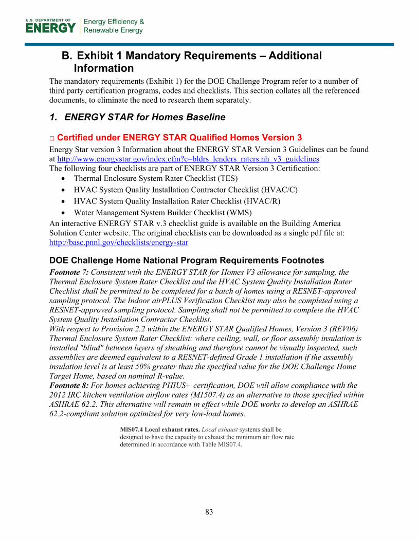
83
B. Exhibit 1 Mandatory Requirements – Additional Information
The mandatory requirements (Exhibit 1) for the DOE Challenge Program refer to a number of third party certification programs, codes and checklists. This section collates all the referenced documents, to eliminate the need to research them separately.
1. ENERGY STAR for Homes Baseline
□ Certified under ENERGY STAR Qualified Homes Version 3 Energy Star version 3 Information about the ENERGY STAR Version 3 Guidelines can be found at http://www.energystar.gov/index.cfm?c=bldrs_lenders_raters.nh_v3_guidelines The following four checklists are part of ENERGY STAR Version 3 Certification:
• Thermal Enclosure System Rater Checklist (TES) • HVAC System Quality Installation Contractor Checklist (HVAC/C) • HVAC System Quality Installation Rater Checklist (HVAC/R) • Water Management System Builder Checklist (WMS)
An interactive ENERGY STAR v.3 checklist guide is available on the Building America Solution Center website. The original checklists can be downloaded as a single pdf file at: http://basc.pnnl.gov/checklists/energy-star
DOE Challenge Home National Program Requirements Footnotes Footnote 7: Consistent with the ENERGY STAR for Homes V3 allowance for sampling, the Thermal Enclosure System Rater Checklist and the HVAC System Quality Installation Rater Checklist shall be permitted to be completed for a batch of homes using a RESNET-approved sampling protocol. The Indoor airPLUS Verification Checklist may also be completed using a RESNET-approved sampling protocol. Sampling shall not be permitted to complete the HVAC System Quality Installation Contractor Checklist. With respect to Provision 2.2 within the ENERGY STAR Qualified Homes, Version 3 (REV06) Thermal Enclosure System Rater Checklist: where ceiling, wall, or floor assembly insulation is installed "blind" between layers of sheathing and therefore cannot be visually inspected, such assemblies are deemed equivalent to a RESNET-defined Grade 1 installation if the assembly insulation level is at least 50% greater than the specified value for the DOE Challenge Home Target Home, based on nominal R-value. Footnote 8: For homes achieving PHIUS+ certification, DOE will allow compliance with the 2012 IRC kitchen ventilation airflow rates (M1507.4) as an alternative to those specified within ASHRAE 62.2. This alternative will remain in effect while DOE works to develop an ASHRAE 62.2-compliant solution optimized for very low-load homes.
MlS07.4 Local exhaust rates. Local exhaust systems shall be designed to have the capacity to exhaust the minimum air flow rate determined in accordance with Table MIS07.4.

84

85
2. Envelope
□ Fenestration shall meet or exceed latest ENERGY STAR requirements The figures below define the ENERGY STAR window requirements for the four ENERGY STAR Qualification Criteria defined climate zones. More information on ENERGY STAR windows can be found in the Building America Solution Center at: http://basc.pnnl.gov/resource-guides/energy-star-windows
DOE Challenge Home National Program Requirements Footnotes Footnote 10: Windows shall meet the ENERGY STAR Window Product Criteria which are in force at the time of the final rating inspection. See www.energystar.gov/windows for current ENERGY STAR Window Product Criteria. Where triple glazed window assemblies with thermal breaks/spacers between the panes are used, such windows are deemed to meet this requirement even in the absence of an ENERGY STAR certification. Footnote 11: Fenestration shall meet the applicable ENERGY STAR Window Product Criteria for U and SHGC, with the following exceptions:
a. An area-weighted average of fenestration products shall be permitted to satisfy the U-factor requirements;
b. An area-weighted average of fenestration products ≥ 50% glazed shall be permitted to satisfy the SHGC requirements;

86
c. 15 square feet of glazed fenestration per dwelling unit shall be exempt from the U-factor and SHGC requirements, and shall be excluded from area-weighted averages calculated using a) and b), above;
d. One side-hinged opaque door assembly up to 24 square feet in area shall be exempt from the U-factor requirements and shall be excluded from area-weighted averages calculated using a) and b), above;
e. Fenestration utilized as part of a passive solar design shall be exempt from the U-factor and SHGC requirements, and shall be excluded from area-weighted averages calculated using a) and b), above. Exempt windows shall be facing within 45 degrees of true South and directly coupled to thermal storage mass that has a heat capacity > 20 btu / ft3x°F and provided in a ratio of at least 3 sq. ft. per sq. ft. of South facing fenestration. Generally, thermal mass materials will be at least 2 in. thick.

87
□ Ceiling, wall, floor, and slab insulation shall meet or exceed 2012 IECC levels Table R402.1.1 from the 2012 IECC is listed below. IECC Window specifications are not applicable to the DOE Challenge Home Program; fenestration criteria are specified in the previous section.
DOE Challenge Home National Program Requirements Footnotes Footnote 12: Insulation levels in a home shall meet or exceed the component insulation requirements in the 2012 International Energy Conservation Code (IECC) - Table R402.1.1. The following exceptions apply:
a. Steel-frame ceilings, walls, and floors shall meet the insulation requirements of the 2012 IECC – Table 402.2.6.
b. For ceilings with attic spaces, R-30 shall satisfy the requirement for R-38 and R-38 shall satisfy the requirement for R-49 wherever the full height of uncompressed insulation at the lower R-value extends over the wall top plate at the eaves. This exemption shall not apply if the alternative calculations in d) are used;
c. For ceilings without attic spaces, R-30 shall satisfy the requirement for any required value above R-30 if the design of the roof / ceiling assembly does not provide sufficient space for the required insulation value. This exemption shall be limited to 500 sq. ft. or 20% of the total insulated ceiling area, whichever is less. This exemption shall not apply if the alternative calculations in d) are used;
d. An alternative equivalent U-factor or total UA calculation may also be used to demonstrate compliance, as follows: An assembly with a U-factor equal or less than

88
specified in 2012 IECC Table 402.1.3 complies. A total building thermal envelope UA that is less than or equal to the total UA resulting from the U-factors in Table 402.1.3 also complies. The insulation levels of fenestration, ceilings, walls, floors, and slabs can be traded off using the UA approach under both the Prescriptive and the Performance Path. Also, note that while ceiling and slab insulation can be included in trade-off calculations, Items 4.1 through 4.3 of the ENERGY STAR for Homes V3 Thermal Enclosure System Rater Checklist shall be met regardless of the UA tradeoffs calculated. The UA calculation shall be done using a method consistent with the ASHRAE Handbook of Fundamentals and shall include the thermal bridging effects of framing materials. The calculation for a steel-frame envelope assembly shall use the ASHRAE zone method or a method providing equivalent results, and not a series-parallel path calculation method.

89
3. Duct System
□ Ducts located within the home’s thermal and air barrier boundary
DOE Challenge Home National Program Requirements Footnotes Footnote 13: Exceptions to locating 100% of forced-air ducts in home’s thermal and air barrier boundary are:
a. Up to 10’ of total duct length is permitted to be outside of the home’s thermal and air barrier boundary. b. Ducts are located in an unvented attic, regardless of whether this space is conditioned with a supply register c. Ducts are located in a vented attic with all of the following characteristics: minimum R-8 duct insulation with an
additional minimum 1.5” of closed-cell spray foam insulation encapsulating the ducts; total duct leakage ≤ 3 CFM25 per 100 ft2 of conditioned floor area; and ductwork buried under at least 2” of blown-in insulation
d. Jump ducts which do not directly deliver conditioned air from the HVAC unit may be located in attics if all joints, including boot-to-drywall, are fully air sealed with mastic or foam, and the jump duct is fully buried under the attic insulation.
e. Ducts are located within an unvented crawl space f. Ducts are located in a basement which is within the home’s thermal boundary g. Ductless HVAC system is used
□Duct Test to Outside Exemption from ENERGY STAR Version 3
ENERGY STAR Version 3: HVAC System Quality Installation Rater Checklist Footnotes Footnote A: For homes that have ≤ 1,200 sq. ft. of conditioned floor area, measured duct leakage to outdoors shall be ≤ 5 CFM25 per 100 sq. ft. of conditioned floor area. Testing of duct leakage to the outside can be waived if all ducts & air handling equipment are located within the home’s air and thermal barriers AND envelope leakage has been tested to be less than or equal to half of the Prescriptive Path infiltration limit for the Climate Zone where the home is to be built. Alternatively, testing of duct leakage to the outside can be waived if total duct leakage is ≤ 4 CFM25 per 100 sq. ft. of conditioned floor area, or ≤ 5 CFM25 per 100 sq. ft. of conditioned floor area for homes that have less than 1,200 sq. ft. of conditioned floor area.

90
4. Water Efficiency
□ Hot Water delivery systems shall meet efficient design requirements
DOE Challenge Home National Program Requirements Footnotes Footnote 14: Hot water delivery systems shall meet efficiency requirements found in Section 3.3 of the EPA WaterSense Single-Family New Home Specification. Under the DOE Challenge Home program, the approved verifier may also confirm compliance with these requirements. These requirements are stated below: Hot Water Delivery System – To minimize water wasted while waiting for hot water, the hot water distribution system shall store no more than 0.5 gallons (1.9 liters) of water in any piping/manifold between the hot water source and any hot water fixture. In the case of occupant-controlled or occupancy sensor-based recirculation systems, the 0.5 gallon (1.9 liter) storage limit shall be measured from the point where the branch feeding the fixture branches off the recirculation loop, to the fixture itself. To verify that the system stores no more than 0.5 gallons (1.9 liters), verifiers shall calculate the stored volume using the piping or tubing inside diameter and the length of the piping/tubing. To account for the additional water that must be removed from the system before hot water can be delivered, no more than 0.6 gallons (2.3 liters) of water shall be collected from the hot water fixture before hot water is delivered. Recirculation systems must be based on an occupant-controlled switch or an occupancy sensor. Recirculation systems that are activated based solely on a timer and/or temperature sensor do not meet this requirement. To verify that the system meets the 0.6 gallon (2.3 liter) limit, verifiers shall first initiate operation of occupant-controlled or occupancy sensor-based recirculation systems, if present, and let such systems run for at least 40 seconds. Next, a bucket or flow measuring bag (pre-marked for 0.6 gallons) shall be placed under the hot water fixture. The hot water shall be turned on completely, a digital thermometer placed in the stream of water just where it meets the water being collected, and the starting temperature recorded. Once the water reaches the pre-marked line (approximately 24 seconds for a lavatory faucet), the water shall be turned off and the ending temperature reading at the same location recorded. The temperature must increase by 10 °F. Only the fixture with the greatest stored volume between the fixture and the hot water source (or recirculation loop) needs to be tested. The figure below shows approximate volumes of water in different piping systems. Please refer to the EPA WaterSense New Home Specification – Guide for Efficient Hot Water Delivery Systems in the appendix for design assistance.

91
5. Lighting and Appliances
□ All installed refrigerators, dishwashers, and clothes washers are ENERGY STAR qualified More information on ENERGY STAR qualified appliances can be found at: http://www.energystar.gov/index.cfm?c=products.pr_find_es_products
□ 80% of lighting fixtures are ENERGY STAR qualified or ENERGY STAR lamps (bulbs) in minimum 80% of sockets More information on ENERGY STAR qualified appliances can be found at: http://www.energystar.gov/index.cfm?c=lighting.pr_lighting_landing
□ All installed bathroom ventilation and ceiling fans are ENERGY STAR qualified More information on ENERGY STAR qualified bathroom fans can be found at: http://www.energystar.gov/index.cfm?fuseaction=find_a_product.showProductGroup&pgw_code=VF More information on ENERGY STAR qualified ceiling fans can be found at: http://www.energystar.gov/index.cfm?fuseaction=find_a_product.showProductGroup&pgw_code=CF

92
6. Indoor Air Quality
□ EPA Indoor airPLUS Verification Checklist and Construction Specifications Refer to the following page for the full EPA Indoor airPLUS Verification Checklist. Section 1 is not required unless the builder is specifically seeking the airPLUS label, which is not mandatory for the DOE Challenge Home Program. The full EPA Indoor airPLUS Verification Checklist and Construction Specifications can be found at: http://www.epa.gov/iaplus01/construction_specifications.html
DOE Challenge Home National Program Requirements Footnotes Footnote 8: For homes achieving PHIUS+ certification, DOE will allow compliance with the 2012 IRC kitchen ventilation airflow rates (M1507.4) as an alternative to those specified within ASHRAE 62.2. This alternative will remain in effect while DOE works to develop an ASHRAE 62.2-compliant solution optimized for very low-load homes.
MlS07.4 Local exhaust rates. Local exhaust systems shall be designed to have the capacity to exhaust the minimum air flow rate determined in accordance with Table MIS07.4.
Footnote 16: The following exception applies to the mandatory requirement to meet the EPA Indoor airPLUS Verification Checklist and Construction Specifications: Compliance with the ENERGY STAR for Homes V3 Water Management System Builder Checklist shall be equivalent to compliance with the EPA Indoor airPLUS Verification Checklist “Moisture Control” provisions (Provisions 1.1 through 1.13). Homes utilizing this exception will not qualify for the Indoor airPLUS label. Builders seeking the Indoor airPLUS label must achieve full compliance with the Indoor airPLUS Verification Checklist.

93

94
7. Renewable Ready
Footnote 17 below states all the conditions that must be met for the renewable checklists to be applicable. Footnote 17: The Renewable Energy Ready Home (RERH) checklists only apply under all of the following conditions:
a. If a solar photovoltaic or solar hot water system is already included with the home, then compliance with the solar photovoltaic or solar hot water RERH checklist, respectively, is not required.
b. Location, based on zip code, has at least 5 kWh/m2/day average daily solar radiation based on annual solar insolation using this online tool: http://gisatnrel.nrel.gov/PVWatts_Viewer/index.html
c. Location does not have significant natural shading (e.g., trees, tall buildings) on the south-facing roof. d. Home as designed has adequate free roof area within +/- 45◦ of true south as noted in the table below. Note that in
some cases a house may have insufficient roof area for the Solar Electric RERH checklist, but it may still have the minimum roof area for the Solar Thermal RERH checklist, and would therefore have to comply with the Solar Thermal RERH checklist. In other cases, the home may only have adequate south facing roof for the Solar Electric or Solar Thermal RERH checklist, but not both. In that case, the builder can decide which one of those two checklists to apply.
Conditioned Floor Area of
House (ft2) Minimum Roof Area for
Solar Electric RERH Checklist (ft2)
Minimum Roof Area for Solar Thermal RERH
Checklist (ft2) ≤ 2000 110 40 ≤ 4000 220 60 ≤ 6000 330 80 >6000 440 100
□ EPA Renewable Energy Ready Home Solar Electric Checklist and Specifications
The Solar Electric Checklist is on page 12, and the full Specifications document (with DOE Challenge Home comments included) is included as an appendix. Footnote 18: For those building sites where the EPA Renewable Energy Ready Home Solar Electric Checklist does apply, the following exceptions are permitted:
a. A permanent roof anchor fall safety system (Provision 2.2) is recommended, but not required.
b. The shading study (Provision 1.4) and the solar site analysis (Provision 1.5) are not required.
c. Blocking is permitted to be used as an alternative to the 4’ x 4’ wood panel area called for in Provision 3.1. The area designated for the future panel to mount PV components shall be clearly noted in the system documentation.
d. As an alternative to installing a 70 Amp double-pole breaker in the electrical service panel for use by the future PV system (Provision 3.4), a labeled slot for a double-pole breaker in the electrical service may be provided.
e. As an alternative to providing architectural drawings of a future solar PV system (Provisions 3.5 and 4.1), builders may provide home buyers with the following information: list of renewable-ready features, available free roof area within +/- 45◦ of true south, location of panel or blocking for future mounting of PV components, location of riser, location of breaker or slot for future breaker in electrical service panel, code-compliant documentation of maximum allowable dead load and live load ratings of the roof, copy of RERH Solar PV Checklist, and copy of RERH Specification Guide.

95
□ EPA Renewable Energy Ready Home Solar Thermal Checklist and Specifications
The Solar Thermal Checklist is on page 13, and the full Specifications document (with DOE Challenge Home comments included) is included as an appendix. Footnote 19: For those building sites where the EPA Renewable Energy Ready Home Solar Water Heating Checklist does apply, the following exceptions are permitted:
a. A permanent roof anchor fall safety system (Provision 2.3) is recommended, but not required.
b. The shading study (Provision 1.4) and the solar site analysis (Provision 1.5) are not required.
c. Blocking is permitted to be used as an alternative to the 3’ x 2’ wood panel area called for in Provision 3.2. The area designated for the future panel to mount solar HW components shall be clearly noted in the system documentation.
d. Homes equipped with an ENERGY STAR qualified whole home gas tankless water heater or an ENERGY STAR qualified heat pump water heater are exempt from Provisions 3.1, 3.2, 3.3, 3.4.
e. As an alternative to providing architectural drawings of a future solar HW system (Provisions 3.6 and 4.1), builders may provide home buyers with the following information: list of renewable-ready features, available free roof area within +/- 45◦ of true south, location of panel or blocking for future mounting of solar hot water system components, location of riser, code-compliant documentation of maximum allowable dead load and live load ratings of the roof, copy of RERH Solar Hot Water Checklist, and copy of RERH Specification Guide.

96

97

98
C. DOE Challenge Home National Program Requirements (Revision 03)

99

100

101

102
103

104

105

DOE/GO-102014-4482 ▪ September 2014
buildingamerica.gov