evaluation of some chemical injection equipment …
TRANSCRIPT

IRRIGATION AND DRAINAGE
Misr J. Ag. Eng., July 2012 -1087-
EVALUATION OF SOME CHEMICAL-INJECTION
EQUIPMENT WITH PRESSURIZED IRRIGATION SYSTEMS
A. M. El Lithy (*)
ABSTRACT
The aim of this research is to evaluate hydraulic performance of
prevailing chemical injection equipment used with pressurized irrigation
systems including; (1) By-pass pressure differential tank, (2) With suction
pipe of irrigation pump, (3) Separate electric centrifugal pump, and (4)
Venturi, to help in selecting an appropriate chemical injector according
to field and operating conditions. The main results in this study can be
summarized in the following:
*The average of injection rates were: 190, 380, 1000, and 1175 for
venturi, by-pass differential tank, with suction pipe of irrigation pump,
and separate electric centrifugal pump respectively, at pressure drop or
irrigation pressure of 100 kPa.
* The average uniformity of injection rate ranged from 94.8 to 99%
during fertigation time for prevailing equipment under study .
* Economical verification of the feasibility of using chemical injectors is
discussed according to different field conditions.
INTRODUCTION
election of proper chemical injection technique in pressurized
irrigation systems is the farmer/ engineer key to higher yields and
healthier crops. Also the choice of suitable fertilizers is also very
important and based on several factors like nutrient form, purity,
solubility, and cost.
It is very important to select a fertilizer injection method that best suits
irrigation system and crop to be grown, whereas each fertilizer or
chemical injector is designed for a specific pressure and flow range. So
care must be taken in selecting a fertigation system that suits farm
condition and requirenment. Caleder and Bert (2007).
(*) Assoc. Prof., Ag. Eng. Dept., Col. of Ag., Al -Azhar U., Assiut.
S
Misr J. Ag. Eng., 29(3): 1087-1100

IRRIGATION AND DRAINAGE
Misr J. Ag. Eng., July 2012 -1088-
Awady in 1992 listed five methods for fertigation devices: 1- with
positive-pressure pump, 2- with venture, 3- differential-pressure tank, 4-
using the main irrigation pump to withdraw fertilizer solution from an
open tank, and 5- hydraulically-actuated pump, the method differ
according to: rate of application, energy consumptive, and price, but they
all must uniformly apply fertilizer over the irrigation area.
Janos (1995 ) stated that to inject the fertilizer solution into the irrigation
system four different fertigators can be used: venturi, by-pass flow tank,
pressure differential system or injection pump. The general advantages of
the injection pump system are: the high degree of control of dosage and
timing of chemical application, centralized and sophisticated control,
portability, no serious head loss in the system, labour-saving and
relatively cheap in operation. With this method the solution is normally
pumped from an open unpressurized tank, and the choice of type of pump
used is dependent on the power source. The pump may be driven by water
flow, by an internal combustion engine, by an electric motor or by a
tractor power take-off.
Kranz et al. (1996) found that chemical injection devices (piston,
diaphragm, and venturi type injection) with the same model number do
not deliver identical calibration curves, outlet pressure significantly
affects the slope of the calibration curve, and the manufacturer calibration
curve may not be appropriate for the operating conditions experienced
with most center pivot installations, for a series of outlet pressures
ranging from 207 to 690 kPa (30 to 100 psi).
Coates et al. (2012) reported that all fertigation techniques performed
well, with fertilizer distribution uniformities between 0.88 and 0.96.
Selection of the optimum site-specific fertigation strategy will depend on
crop needs, scheduling limitations, and system design parameters such as
emitter type, fluid travel time, and slope.
Bakeer (2002) (a and b) and Badr et al. (2006) recommended avoiding
fertigation devices that depend on the differential pressure between the
inlet and outlet as much as possible and using hydraulically actuated
chemigator for saving water, energy and money.
IRRIGATION AND DRAINAGE
Misr J. Ag. Eng., July 2012 -1089-
On the middle of 90s, some of the farmers injected the fertilizer through
the irrigation system by the suction pipe of the irrigation water pumps,
many of the farmers are used to it nowadays (39.4%). EL Zuraiqi S. et
al. (2004).
Jiusheng et al. (2007) stated that both manufacturing variability of
emitters and injector types had a very significant effect on the uniformity
of fertilizer applied, while the uniformity of water application was mainly
dependent on emitter type.
Kassem and AL-Suker (2009) reported that fertigation using injection
pump records efficient and highest values of water and nitrogen use
efficiency for wheat and barley crops, among different methods used,
according to the experimental results during 2006/2007 and 2007/2008
seasons in experimental farm conditions of, Al-Qassim University.
The aims of this research are:
1. Study the affecting factors on use of chemical injection equipment for
the maximum operating efficiency according to field conditions.
2. Evaluate the available injection equipment used in irrigation system for
proper operation and maintenance, and
3. Conduct field experiments to identify the operating and hydraulic
criteria for chemical injection at different field conditions.
MATERIALS AND METHODS
Field experiments were conducted in a private farms in “ El Sharqia “
governorate that included wide variety of parameters and field conditions
as presented in table 1 to collect hydraulic and engineering data, that help
to select proper injection equipment according to field conditions.
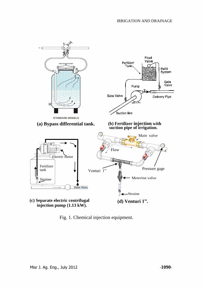
(CIU). equipmentchemical injection prevailingComponents of the
The components and required data in addition to drawings of chemical
injection equipment used in the study, are presented in table 2 and fig. 1
(a,b,c and d) as follows:
(1) By-pass differential tank. (Fig.1 a).
(2) With suction pipe of irrigation pump. (Fig.1 b).
(3) Separate electric centrifugal pump. (Fig.1 c), and
(4) Venturi (Fig.1 d).
IRRIGATION AND DRAINAGE
Misr J. Ag. Eng., July 2012 -1090-
Fig. 1. Chemical injection equipment.
(b) Fertilizer injection with suction pipe of irrigation.
(a) Bypass differential tank.
(c) Separate electric centrifugal injection pump (1.13 kW).
Electric motor
Fertilizer tank
(d) Venturi 1”.
Flow
Main valve
Straine
r
Metering valve
Venturi 1” Pressure gage
Strainer

IRRIGATION AND DRAINAGE
Misr J. Ag. Eng., July 2012 -1091-
بلبيس ، العادليت ، عرابى ، العادليت على الترتيب. *
# قناة الاسماعيليت.
Table 1: The actual farm condition under investigation including
engineering and hydraulic criteria of irrigation system
Farm conditions Farm under case study
A B C D
1-Location Belbeis* Adleia* Orabi* Adleia*
2-Area,fed. 70 8 7 10
3-Irrigation system Trickle irrigation systems
4- Water source Well Ismailia
canal
Ismailia
canal #
Under- ground
reservoir
5- Crop Mango Orchard Mango Pomegranate
6-Tree spacing 4 X 2 6 X 3 3 X 1.75 3 x3.5
7- Distance from water source and pump unit, m.
600 1600 400 150
8- Pump discharge m
3/ h.
120 130 50 70
9- System pressure, bar. (kPa.).
3 (300) 1.5(150) 3.5(350) 2.5(250)
10-Irrigation time ,h. 10 2 10 2-6
11- Average of chemical injection/irrigation time, m
3/ h.
1.0 0.2-0.5 0.2-1.0 0.5-1.0
12. Power source Electricity Hydraulic Electricity Diesel
13. Injection equipment tested
Separate
electric
centrifugal
injection
pump (1.13
kW).
(Fig.1 c).
Venturi 1"
(Fig.1 d).
With suction
pipe of
irrigation
pump.
(Fig.1 b).
By-pass
differential
tank. (Fig.1
a).

IRRIGATION AND DRAINAGE
Misr J. Ag. Eng., July 2012 -1092-
Chemical injection rate:
The chemical injection rate was measured for equipment (b, c, and d) by
recording chemical decreasing level in chemical tank with time using
measuring tape with accuracy of 1mm. and stop watch. Whereas for the
chemical injection unit (a) EC meter (rang from 0 to 3 mmhos/cm with
accuracy of 0.01 mmhos/cm (± 2%) ), was used to record EC reading of
irrigation water during injection time till reaching to the same reading of
irrigation water EC recorded before starting of chemicals injection from
chemical tank of known capacity. (That means the chemical in the
chemical tank was ejected to the irrigation system).
Table2: Hydraulic and engineering specs for chemical injection equipment.
Injector
specifications
CHEMICAL INJECTION EQUIPMENT
(1)
By-pass
differential
tank. (Fig.1 a).
(2)
With suction pipe of irrigation
pump. (Fig.1 b).
(3)
Separate electric centrifugal
injection pump (1.13 kW). (Fig.1 c).
(4)
Venturi 1" (Fig.1 d).
Operating
pressure range,
(kPa.)
200-800 200-400 200-400 200-400
Injection rate,
m3/h.
0.120-0.350 0.1-4 0.1-1.8 0.1-0.4
Required power
source Hydraulic Electric/diesel Electric Hydraulic
Connection,
Inch (“). 3/4” 1” 1.1/4” / 1” 1”
Total mass, kg. 45 0.5 18 0.75
Tank capacity,
m3 0.12 1 1 0.2-1
Construction
material steel Chemical-resistant plastics
Stainless steel
Chemical-
resistant
plastics

IRRIGATION AND DRAINAGE
Misr J. Ag. Eng., July 2012 -1093-
Irrigation pressure and pressure drop:
Pressure gages ranging from 0 - 600 kPa with an accuracy of 10 kPa were
used to measure the working pressure of the irrigation system with
separate electric centrifugal injection pump and with suction pipe of
irrigation pump equipment. The pressure drop was measured using two
pressure gages connected before and after chemical injector equipment
for venturi and by-pass pressure differential tank.
Injection uniformity.
The uniformity of injection rate during injection time was determined
using Cheristiansen coefficient “CU” Christiansen (1942)
CU = (1-) . 100
where :
CU: coefficient of uniformity
: absolute mean deviation of injection rate on injection time.
Correlation between measured and calculated data. The following equation was used to calculate correlation between
measured and calculated data. (Nigm, 1993 in Arabic).
R2 =∑ 𝑥 − 𝑥 𝑦 − 𝑦
𝑛 . 𝜎𝑥 .𝜎𝑦
Where: R2 = correlation between two groups of data, x = data number in
the first group, x, y = average, y = data number in the second group
x, y = standard deviation, and n = number of data.
RESULTS AND DISCUSSION
Hydraulic characteristics of chemical injection equipment (CIE).
Fig. 2 shows the relation between injection rate and pressure drop for
different injectors tested with irrigation system, under the same operating
conditions. It is clear that an increasing of injection rates was recorded for
venturi (from 90 to 395 L/h) and by-pass differential tank (from 160 to
620 L/h) by increasing of pressure drop from 40 to 140 kPa. Whereas
injection rate for separate pump decreased from 1280 to 1030 L/h. by

IRRIGATION AND DRAINAGE
Misr J. Ag. Eng., July 2012 -1094-
increasing of irrigation pressure from 40 to 140 kPa., due to pump
characteristics, as presented in table 2 used to inject chemicals from
chemical tank to irrigation system. Discharge decreasing by increasing
the resistance to injection rate is caused by increasing of irrigation system
pressure. It is clear also that using of suction pump pipe to inject chemical
with irrigation system was not affected by irrigation pressure increasing
from 40 to 140 kPa., and it recorded a constant injection rate of 1000 L/h
due to the great difference between maximum chemical injection rate (1
m3/ h) and irrigation pump discharge rate (50 m
3/ h) as presented in table
1. That gave more stability for this technique of chemical injection
against wide range of irrigation system pressure changes.
Injection rate during injection time.
Fig. 3 reflects the effect of operating time on injector rate for available
chemical injection equipment. The average of injection rate for venturi,
with suction pipe of irrigation pump, and separate electric centrifugal
pump, were 190, 1000, and 1175 respectively.
Fig. 2 : Performance of chemical injectors.

IRRIGATION AND DRAINAGE
Misr J. Ag. Eng., July 2012 -1095-
Fig. 3: Injection rate for different chemical injection equipment
during injection time at pressure drop of 100 kPa.
Injection rate uniformity during injection time.
Fig. 4 shows the effect of pressure drop or irrigation system pressure on
injection rate uniformity during the injection time for different equipment
used for chemical injection in irrigation systems. The highest value of
injection rate uniformity ranged from 98.8 to 99 % recorded with using
suction pipe of irrigation pump to inject chemical in irrigation system.
Whereas, by increasing irrigation system pressure from 40 to 120 kPa, the
uniformity of injection rate decreased from 98.8 to 95.2 % for chemical
injection using separate pump due to increasing the resistance of chemical
injection by increasing irrigation system pressure. Meanwhile, there ware
no significant effects of pressure drop or irrigation system pressure
increasing on the uniformity of injection rate during injection time for
other injection equipment according to experiment conditions.
Hydraulic characteristics of designed and imported types of chemical
injectors.
The relation between injection rate and pressure drop or irrigation system
pressure for chemical injector equipment under study is expressed in three
equations, shown in fig. 5 for each injector with acceptable correlation
between measured and calculated data (84-94 %).

IRRIGATION AND DRAINAGE
Misr J. Ag. Eng., July 2012 -1096-
Fig. 4: Effect of pressure drop or irrigation pressure on
injection rate uniformity for different chemical
injection equipment.
Fig. 5: Hydraulic characteristics of chemical injector equipment.
Cost comparison.
Table 3 shows the total initial cost for different prevailing equipment used
in chemical injection in irrigation system under study were 450, 350,
3200 and 550 L.E. for (a) Pressure differential Tank, (b) with irrigation
suction pump, (c) using separate pump, and (d) venturi 1" respectively.
As a result of using suction pipe of irrigation pump to inject chemical in
irrigation system, a saving of about 29% and 57% was obtained compared
with using pressure differential tank or venturi for chemical injection in

IRRIGATION AND DRAINAGE
Misr J. Ag. Eng., July 2012 -1097-
irrigation line. Meanwhile, using separate pump record the highest cost
among other equipment.
Table 3: Cost details and comparison between designed and imported chemical injectors.
*Material cost according to local market price, 2012. ** Local fabricated chemical fertilizer tank price with capacity of 120
liter according to local market price, 2012.
SUMMARY AND CONCLUSION
An evaluation of prevailing chemical injector equipment was carried out
to help in selecting the proper chemical injector according to field and
operating conditions.
Chemical injection equipment under study were: (a) pressure differential
tank, (b) with irrigation suction pump, (c) using separate pump, and (d)
venturi 1" ,.
The main results in this study can be summarized in the following:
*The average injection rate was recorded for venturi, by-pass differential
tank, with suction pipe of irrigation pump, and separate electric
centrifugal pump: were 190, 380, 1000, and 1175 L/h. respectively at
differential pressure drop of 100 kPa.
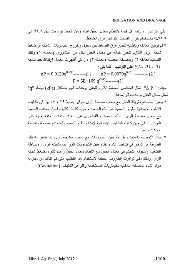
* Three equations, derived from curve fitting of characteristics curve, can
be used to get the injection pressure required for injected flow rate with
an acceptable correlation of 94 %, for venturi (Eq. 1), and 94, 84% for
(differential pressure tank and separate pump), (Eq. 2 and 3) respectively
as following equations:
∆P = 0.0139q0.795
--------)∆P = 0.0079q0.816
-------- (2 )
*Material
Cost, L.E.*
(a) P. Dif. Tank
(b) with irr. s. pump
(c) separate pump
(d) venturi 1"
Injector ** 350 0 0 450 Engine with pump 0 0 2650 0 Valves and connectors
100 100 150 150
Chassis for fixing 0 0 150 0 Fertilizer tank 0 250 250 250 Total 450 350 3200 550

IRRIGATION AND DRAINAGE
Misr J. Ag. Eng., July 2012 -1098-
P = 5E+169 q-5.45
--------)
Where: “q” is the rate of injection, L /h, “∆P” pressure drop, kPa . “P”
irrigation pressure, kPa.
*The total initial costs for different available equipment used for chemical
injection in irrigation system under study were 450, 350, 3200 and 550
L.E. for (a) pressure differential tank, (b) with irrigation suction pump, (c)
using separate pump, and (d) venturi 1" respectively.
*A saving of about 29% and 57% was obtained in injection rate with
using with irrigation suction pump technique compared with using
pressure differential tank or venturi for chemical injection in pressurized
irrigation system.
*The highest value of injection rate uniformity ranging from 98.8 to 99 %
was recorded with using suction pipe of irrigation pump, whereas the
lowest value of injection rate uniformity ranging from 94.8% to 95.6 %
was recorded with using pressure differential tank to inject chemical in
irrigation system.
REFERENCES
Awady, M. N., 1992, Irrigation by trickling methods, Amer U. in Cairo,
Desert Dev. Center, Ir. Traing. Prog.: 50 P. (In Arabic).
Badr, A. A., Ebabi, F. G., and ELtomy, E. O., 2006, Fertigation
methods effects on water and fertilizer uniformity in drip irrigation,
Misr J. Ag. Eng., 23(1): 122 – 136.
Bakeer, G. A., 2002 a, Chemical injection effect on deep whell-pump in
drip irrigation, Misr J. Ag. Eng., 19(4): 821- 840.
Bakeer, G. A 2002 b, Fertigation methods effects on water and fertilizer
uniformity in drip irrigation, Misr J. Ag. Eng., 19(4): 821- 840.
Caleder, T. and Bert, J., 2007, Selection of fertigation equipement,
http://www.agric.wa.gov.au/objtwr/imported_assets/cotent/hort/eng/
f03501.pdf (Accessed on October 2009).
Christiansen, J.E., 1942, Irrigation by Sprinkling. California Agriculture
Experiment Station Bulletin, No. 670.
Coates, R. W., Sahoo, P. K., Schwankl, L. J. and Delwiche, M. J.,
2012, Fertigation techniques for use with multiple hydrazones in
simultaneous operation. Precision 13(2): 219-235.

IRRIGATION AND DRAINAGE
Misr J. Ag. Eng., July 2012 -1099-
EL Zuraiqi, S., Rusan, M. J., and AL Qawasmi, W., 2004, Fertigation
in Jordan, IPI Regional Workshop on Potassium and Fertigation
development in West Asia and North Africa; Rabat, Morocco: 24-
28.
Janos, L. 1995, Application of chemicals through irrigation systems. ICID
J. 45 No. 2: 125-146.
Jiusheng, L., Yibin, M., and Bei, L., 2007, Field evaluation of fertigation
uniformity as affected by injector type and manufacturing variability
of emitters, Ir. Sc., Volume 25 (2): 117-125.
Kassem, M. A. and AL-Suker, A., 2009, Effect of fertigation methods on
productivity and nitrogen use efficiency for wheat and barly crops,
Misr J. Ag. Eng., 26(2): 866- 885.
Kranz, W. L., Eisenhauer, D. E., Parkhurst, A. M., 1996, Calibration
accuracy of chemical injection devices, Applied Engineering in
Agriculture. 12(2): 189-196.
Negm, A. M., 1993, Descriptive and analytical statistics by using ready
made software, P. 199.(In Arabic).
الملخص العربى
تقييم لبعض معذاث حقن الكيماوياث بأنظمت الري الضغطى
حمذ ماهر الليثى أد / (*)
شائؼح الاسرخذاو انكياياخ انضساػيح حم ؼذاخ نالأداء انيذسن ذمييىان يذف انثحث
( يغ خظ انسحة 2( خضا انرسيذ ، )1شم انؼذاخ انرانيح : ) ،تأظح انش انضغط
تضاسع ( انفشس ، لذ اخشيد انرداسب انحمهيح 4( تضخح يفصهح ، )3خح انش، )نض
شهد ظشف حمهيح يخرهفح ، رنك نهساػذج ف اخرياس اسة يؼذج خاصح تطمح انششليح
انرائح فيا يه: ذرهخصنحم انكياياخ تأظح انش طثما نهظشف انحمهيح
خ يغ ييا انش نكم ي انفشس ؼذلاخ حم انكيايانذى انحصل ػه يرسطاخ *
1115، 1111، 381، 191انرسيذ يغ خظ انسحة نضخح انش تضخح يفصهح خضا
.كيه تاسكال 111فشق ضغظ رنك ػذ نرش/ساػح ػه انرشذية
% 99إن 98.8ذشاحد تي نؼذل انحم صييح أظشخ انرائح أ أػه إرظاييح *
كيه تاسكال 121إن 41تإسرخذاو سحة يضخح انش نحم انكياياخ ػذ فشق ضغظ تي
.فرع أسيىط –ج. الأزهر –السراعت ك. –أستار الهنذست السراعيت المساعذ (*)
IRRIGATION AND DRAINAGE
Misr J. Ag. Eng., July 2012 -1100-
إن 94.8ػه انرشذية ، تيا ألم ليح لارظاو يؼذل انحم أثاء صي انحم ذشاحد تي
فشق انضغظانرسيذ ػذ فس خضا % تإسرخذاو95.6
ي دخل خشج انكياياخ تشثكح أ ضغظ تضغظ فشق انرمذيش ذى ذفيك يؼادنح سياضيح ن*
ذك ( 1)يؼادنح انفشسنكم ي انحمكذانح ف يؼذل حمانلاصو نه شثكح انش
، انر أظشخ يؼايم اسذثاط خيذ تسثح (3)يؼادنح تضخح يفصهح (2)يؼادنح انرسيذ
، كا يه : ػه انرشذية% 84 ،94، 94
∆P = 0.0139q0.795
--------)∆P = 0.0079q0.816
-------- (2 )
P = 5E+169 q-5.45
--------)
" q( تيا، "kPaتحذاخ كيه تاسكال ) حمانلاصو نه ضغظان اخفاض " ذثم∆ Pحيث: "
/ساػح.نرشتحذاخ يؼذل انحم ذثم
ذكانيف % ف 51، 29إسرخذاو طشيمح انحم يغ سحة يضخح انش ترفيش تسثح ريضي*
نطشق انرسيذ ػ ذك انرسيذ ، حيث كاد ذكانيف اشاء يؼذاخ انرسيذ الاشاء الاترذائيح
خي ػه 551، 451، 351يغ سحة يضخح انش ، ذك انرسيذ ، انفشس
انرشذية ، ف حي كاد انركانيف الاترذائيح لاشاء ظاو نهرسيذ تإسرخذاو يضخح يفصهح
خي. 3211
يك انرصيح تإسرخذاو طشيمح حم انكياياخ يغ سحة يضخح انش نا ذريض ت ذهك *
انطشيمح ي ذفيش ف ذكانيف اشاء ظاو حم انكياياخ انضساػيح تشثكح انش ، تساطح
تضغظ شثكح انرشغيم سنح انرحكى ف يؼذل انحم يغ ارظاو يؼذل انحم ػذو ذأثش
، ير ذى انرأكذ ي يمايح افشخ انظشف انحمهيح لاسرخذاو زا انظاوذ يرانش رنك
.(Cavitation)ياد اشاء انضخح انذاخهيح نهكياياخ انسرخذيح ظاش انركف