evaluation of pyrochemistry in molten salts for recycling
TRANSCRIPT

HAL Id: tel-03144256https://tel.archives-ouvertes.fr/tel-03144256
Submitted on 17 Feb 2021
HAL is a multi-disciplinary open accessarchive for the deposit and dissemination of sci-entific research documents, whether they are pub-lished or not. The documents may come fromteaching and research institutions in France orabroad, or from public or private research centers.
L’archive ouverte pluridisciplinaire HAL, estdestinée au dépôt et à la diffusion de documentsscientifiques de niveau recherche, publiés ou non,émanant des établissements d’enseignement et derecherche français ou étrangers, des laboratoirespublics ou privés.
Evaluation of pyrochemistry in molten salts for recyclingLi-ion batteries
Patricia Nathaly Ruiz Onofre
To cite this version:Patricia Nathaly Ruiz Onofre. Evaluation of pyrochemistry in molten salts for recycling Li-ionbatteries. Chemical Physics [physics.chem-ph]. Sorbonne Université, 2019. English. �NNT :2019SORUS346�. �tel-03144256�
Sorbonne Université
Ecole doctorale de Chimie Physique et Chimie Analytique de Paris Centre
Laboratoire PHENIX / Equipe Electrochimie et Liquides Ioniques
Evaluation of pyrochemical method for the recycling of Li-
ion batteries
Présentée Par Patricia Nathaly Ruiz Onofre
Thèse de doctorat de Chimie-Physique
Dirigée par Dr. Anne-Laure Rollet
Présentée et soutenue publiquement le 1 octobre 2019
Devant un jury composé de :
M. Pierre Chamelot Professeur, Université Paul Sabatier, Toulouse III Rapporteur
M. Alexandre Chagnes Professeur, Université de Lorraine Rapporteur
Mme. Laurence Croguennec Directrice de Recherche, Université de Bordeaux Examinatrice
Mme. Delphine Vantelon Responsable de ligne, Synchrotron SOLEIL Examinatrice
M. Hubert Perrot Directeur de Recherche, Sorbonne Université Examinateur
Mme. Anne-Laure Rollet Chargée de Recherche, Sorbonne Université Directrice de thèse
Mme. Virginie Lair Maitre de Conférences, Chimie Paristech Co-Encadrante


2
Dédicace
A ma famille, Alexis et mes amis
En mémoire de mon oncle et de ma grand-mère Jaime et Marujita
“El mundo está en manos de aquellos que
tienen el coraje de soñar y de correr el
riesgo de vivir sus sueños”
Paulo Coelho
‘El Alquimista’

3
Remerciements
Je remercie MM. Pierre Chamelot et Alexandre Chagnes pour m’avoir fait l’honneur de
rapporter ce présent manuscrit ainsi que l’ensemble des membres du jury.
Ces travaux ont été réalisés au sein du laboratoire PHENIX et de l’Institut de Recherche
de Chimie Paris - IRCP. Je remercie MM. Pierre Levitz et Laurent Michot (ancien et actuel
directeur du laboratoire PHENIX- UMR 8234), ainsi que M. Michel Mortier (directeur de
l’IRCP UMR 8247), qui m’ont accueillie et ont permis la concrétisation de mes recherches
pendant ces trois années.
Je tiens également à remercier ma directrice de thèse Mme Anne-Laure Rollet ainsi que
tous mes encadrants : Mmes. Virginie Lair et Denise Krulic et MM. Damien Dambournet et
Michel Cassir. Chacun, avec ses compétences et ses expertises dans des domaines respectifs, a
permis la réalisation de cette étude. La multiplicité d’idées a représenté un réel défi pour aboutir
à un seul et unique manuscrit, et nous sommes parvenus ensemble à finaliser cette thèse. J’en
tire une grande fierté.
Je remercie aussi toute l’équipe ELI pour son accueil :
MM. Fréderic Lantelme et Nicolas Faturros pour leurs conseils et leur participation
active à ce projet. Mme. Sandrine Leclerc de s’être assurée au quotidien que je dispose du
nécessaire dans mon espace de travail. Mme. Ana Gabriela Porras pour son aide au cours de
mes deux premières années de thèse.
Je voudrais adresser un remerciement spécial à M. François Dardoize pour tous ses
encouragements, conseils et idées tout au long de cette thèse et également un immense merci à
M. Didier Devilliers pour avoir été un mentor scientifique très présent tout au long de ces trois
ans et pour sa précieuse aide en électrochimie.
Un grand merci également à tous les non permanents qui ont participé à ce projet :
Arturo Melendez Ceballos (post-doc) et Gabriele Miranda (stagiaire) pour leur implication dans
l’étude de composés organiques de batteries présentée dans cette thèse, ainsi qu’aux étudiantes
Natacha Wonneberg, Agnieszka Dynowska et Zohreh Safarzadeh Kermani.
4
Une thèse en sels fondus à haute température est un défi où les contraintes techniques
sont présentes au quotidien. Cette entreprise difficile a été rendue possible grâce à la précieuse
aide de « bricoleurs » du laboratoire, de l’atelier de verre et du Synchrotron SOLEIL. C’est
ainsi que je remercie M. Jean Chevalet et Mme Flori Lopis pour toute leur aide dans la soudure,
la réparation, la mise en forme des matériaux et leur bonne humeur toujours présente. Je
remercie de manière spéciale M. José Gomes ainsi que Mme Anne-Laure Rollet et toute
l’équipe de la ligne ROCK du Synchrotron SOLEIL pour leur implication dans le
développement de la cellule présentée dans ce manuscrit. Je ne remercierai jamais assez Mme.
Valerie Briois et M. Laurent Barthe pour leur disponibilité et leur dynamisme lors du créneau
des mesures à SOLEIL.
La logistique de cette thèse a été faite avec beaucoup d’efficacité grâce à Mmes. Lise
Michelot, Brigitte Carrez, Stéphanie Grison et M. Gérard Guillard : un grand merci. Je tiens
aussi à citer et à adresser mes vifs remerciements à toutes les personnes qui m’ont permis de
mener à bien les multiples caractérisations au cours de cette thèse : Mme. Delphine Talbot,
Mme. Aude Michel Tourgis, M. Mohamed Selmane et M. David Montero.
Cette aventure a été marquée de formidables rencontres qui se sont transformées en
amitiés profondes. Parmi ces personnes j’ai une pensée spéciale pour Nadia, Lisbeth,
Chérazade, Etienne, Kyle, Anastasia et Seongkoo qui ont été là pour me soutenir au jour au
jour, surtout dans la période la plus difficile de cette aventure qu’est la rédaction.
Je porte une pensée douce pour toutes les personnes qui m’ont soutenue depuis le début
de ma vie : mes parents, ma sœur et mon frère. De plus, une immense reconnaissance à toi,
Alexis pour marcher avec moi tout au long de cette aventure et pour ton inconditionnel soutien
surtout pendant la rédaction de ce manuscrit. Et enfin, j’adresse un grand merci à tous mes amis
pour leurs encouragements indéfectibles et en particulier à : Sophie, Jacques, Christine,
Rodolphe, Guillaume, Johanna, Jessica, Julien et Caterina.
Je termine ces remerciements par une pensée pour tous ceux qui sont encore en chemin
vers l’obtention de ce diplôme. Sachez que, comme disait Nelson Mandela, « Cela paraît
impossible jusqu’à ce que ce soit fait ».

Summary
Remerciements ........................................................................................................................... 3
Summary .................................................................................................................................... 5
General introduction ................................................................................................................... 7
Chapter I: State of art ............................................................................................................... 10
1. Introduction ................................................................................................................... 11
2. Batteries generalities ..................................................................................................... 11
2.1. Working principle .................................................................................................. 11
2.2. The Li-ion battery elements ................................................................................... 13
2.3. Importance of Li-ion batteries................................................................................ 16
3. Recycling generalities ................................................................................................... 18
3.1. Geopolitical and social issues of Li-ion batteries material supply......................... 20
3.2. Recycling definition and its importance ................................................................ 23
3.3. Existing Li-ion batteries recycling methods .......................................................... 26
3.4. Legislative initiatives for facing the difficulties of recycling ................................ 29
4. Molten salts generalities ................................................................................................ 31
4.1. Definition, classification and properties ................................................................ 31
4.2. Examples of molten salts applications ................................................................... 31
4.3. Choice of molten salts systems .............................................................................. 34
5. Strategy .......................................................................................................................... 39
Chapter II: Study of Li-ion battery compounds in molten salts by X-ray absorption
spectroscopy ............................................................................................................................. 40
1. Introduction ................................................................................................................... 41
1.1. X-ray absorption spectroscopy (XAS) technique .................................................. 42
2. Results and discussion ................................................................................................... 46
2.1. Developing a new device for in situ XAS measurements in molten salts ............. 46
2.2. Reliability of the high temperature device for in situ XAS measurements ........... 54
2.3. In-situ measurement of LiCoO2 (LCO) in molten Li2CO3-Na2CO3-K2CO3 eutectic
56
3. Conclusions ................................................................................................................... 63
Chapter III: Study of Li-ion battery compounds in molten carbonates medium...................... 64
1. Introduction ................................................................................................................... 65

6
2. Experimental part .......................................................................................................... 67
2.1. Experimental set-up ............................................................................................... 68
2.2. Electrochemical measurements .............................................................................. 71
2.3. Other characterizations .......................................................................................... 72
3. Results and Discussion .................................................................................................. 73
3.1. Metallic cobalt dissolution ..................................................................................... 73
3.2. Electrochemical behavior of cobalt in molten carbonates ..................................... 74
3.3. Battery organic compounds in molten carbonates ................................................. 93
4. Conclusions ................................................................................................................... 96
Chapter IV: Study of Li-ion battery compounds in molten chlorides medium ........................ 98
1. Introduction ................................................................................................................... 99
2. Experimental part ........................................................................................................ 101
2.1. Molten salt preparation ........................................................................................ 101
2.2. Electrochemical measurements ............................................................................ 102
2.3. Other characterizations ........................................................................................ 103
3. Results and discussion ................................................................................................. 104
3.1. Electrochemical stability window of molten LiCl-KCl eutectic .......................... 104
3.2. Electrochemical study of CoCl2 precursor in molten LiCl-KCl eutectic ............. 105
3.3. Electrochemical study of LiCoO2 in molten LiCl-KCl eutectic .......................... 108
3.4. NaHSO4.H2O addition influence on LiCoO2 dissolution in molten LiCl-KCl
eutectic ........................................................................................................................... 111
3.5. Influence of NaHSO4.H2O on LiCoO2 solubility in molten LiCl-KCl eutectic .. 123
3.6. Electrochemical study of LiCoO2 pretreated with NaHSO4.H2O in molten LiCl-
KCl eutectic .................................................................................................................... 127
4. Conclusions ................................................................................................................. 137
General conclusions and perspectives .................................................................................... 139
References .............................................................................................................................. 143
List of figures ......................................................................................................................... 152
List of tables ........................................................................................................................... 158
General Introduction
7
General introduction
The end of the 20th and the beginning of the 21st century have been marked by very
significant technological innovations specially in communications and energy fields.
In fact, a digital revolution or third industrial revolution has quickly changed our society
with the public access of the internet, the apparition of cell phones, tablets, among others.
Moreover, the continuous increase of global warming produced by the emission of
greenhouse gases is one of the biggest concerns of our societies nowadays. The 21st Conference
of the Parties (COP21) leads to the adoption of the Paris agreement, which engaged the different
nations to reduce their gas emissions and hold the increase of global average temperature below
2°Ca. As a consequence, investments in the development of renewable energies as alternative
to accelerate the decarbonization of energy production and transports are rising.
The energy storage is a crucial aspect for the improvements of the digital revolution and
the energetic transition. As a consequence, different energy storage systems have been
developed according to the applications, especially Li-ion batteries in the last years. In this way,
they have become part of our daily lives. Every year, there is a growth of their production,
especially since 2004b,c . This trend is expected to continue in the future. Nevertheless, some of
the materials present in this kind of batteries are distributed in an inhomogeneous way in the
planet and they come from limited resources. Recycling appears as an alternative to face the
future shortage of these materials and contributes to the reduction of wastes. Recycling can play
an essential role in the lessening of the environmental impacts related to batteries production
and disposal at the end of their life d.
_______________________
a https://unfccc.int/process-and-meetings/conferences/past-conferences/paris-climate-change-
conference-november-2015/cop-21( consulted in July 2019)
b Report ALBERMARLE. Global Lithium Market Outlook; 2016
c Report Avicenne Energy. Lithium-Ion Battery Raw Material Supply and Demand 2017-2025; 2018
d Gaines, L.; Richa, K.; Spangenberger, J. Key Issues for Li-Ion Battery Recycling. MRS Energy
Sustain. 2018, 5, 1–14. https://doi.org/10.1557/mre.2018.13.

General Introduction
8
Different methods have been developed for recycling batteries. Hydrometallurgy and
pyrometallurgy are the most widely used in industry. They are very efficient for metals
recycling. Nevertheless, these methods do not valorize the organic compounds from batteries.
Organic compounds are most of the times burned and the volatized products are usually harmful
gases and compounds. An important budget must always be planned for the gas treatment d.
The portion of organic compounds in a battery is significant. For example, a Li-ion
battery is constituted of about 15% organic chemicals and 7% plastics, varying slightly with
different manufacturers e. This statement justifies the need to develop other new methods for
recycling, enabling the valorization of both kind of compounds in one system. In this regard,
molten salts systems are promising candidates. In fact, this kind of solvents are widely applied
as solvents for different metals recovery and manufacturing by electrolysis such as: aluminum,
magnesium, sodium, molybdenum, tungsten, niobium, among others f,g,h,i,j.
Furthermore, some molten salts systems have the capacity of trapping and/or
decomposing hazardous organic compounds k. This can be an advantage for lessening all the
gas treatment processed after the recycling of batteries. Phenix laboratory is historically known
for its research in molten salts. Nevertheless, the research on this project started in Phenix
Laboratory with this thesis work. We chose to focalize ourselves in Li-ion batteries recycling
and especially in cobalt recovery.
______________________
e Al Hossaini Shuva, M.; Kurny, A. S. W. Hydrometallurgical Recovery of Value Metals from Spent
Lithium Ion Batteries. Am. J. Mater. Eng. Technol. 2013, 1 (1), 8–12.
f Beck, T. R. Hall and Héroult and the Discovery of Aluminum Electrolysis. Electrochem Soc.
Interface 2014, 23 (2), 36–37
g Wulandari, W.; Brooks, G.; Rhamdhani, M.; Monaghan, B. Magnesium: Current and Alternative
Production Routes. In Chemeca 2010: Australasian Conference on Chemical Engineering; 2010.
h Dandapani, K. S.; Srinivasan, L. K. Production of Magnesium in 30 A Cells. Electrometall. Thermics
1987, 3 (2), 127–129.
i Senderoff, S.; Mellors, G. W. Coherent Coatings of Refractory Metals. Science (80-. ). 1966, 153
(3743), 1475–1481.
j Sethi, R. S. Electrocoating from Molten Salts. J. Appl. Electrochem. 1979, 9, 411–426.
k Alam, M.; Kamath, S. Cyanide Destruction in Molten Carbonate Bath: Melt and Gas Analyses.
Environ. Sci Technol. 1998, 32, 3986–3992.

General Introduction
9
This manuscript is divided in four chapters:
The first chapter provides a bibliographic overview of Li-ion batteries recycling and the
existing challenges inherent to it. First, generalities and fundamental notions about batteries and
their recycling will be introduced. In a second place, molten salts generalities will be presented
as well as their principal properties and applications. Especial attention will be paid to the
properties of the molten salt families chosen for this study. Finally, the strategy for this research
project will be presented to conclude this chapter.
The second chapter is dedicated to the study of cobalt speciation in molten salts by X-
ray absorption spectroscopy (XAS). Fundamental notions about this technique will be presented
in a first place. The conception of an adapted device for XAS measurements at high
temperatures in molten salt systems is then discussed. Cobalt average oxidation state and its
speciation as function of temperature will be finally presented.
The third chapter is dedicated to the study of electrochemical behavior of cathode
materials from Li-ion batteries in molten carbonates. The dissolution of cobalt from these
compounds will be characterized in this molten medium. The results regarding the possibility
of recovering metallic cobalt of these cathodes by electrochemical means will be discussed.
Finally, preliminary results of the behavior of organic Li-ion battery compounds will be
described.
The fourth and last chapter is focused on the study of cathode material LiCoO2 in molten
chlorides. The results of the dissolution of cobalt from this material in this medium will be
discussed. Then in a second place, the influence of additives on the dissolution will be
described. Results will bring new insights on the best protocol to be used to have the optimal
results. Finally, evidences of cobalt recovery from cathode materials by electrochemical means
will be shown.
Finally, this manuscript will be closed by general conclusions and perspectives of this
research.

Chapter I: State of art
“Dans la vie, rien n'est à craindre,
tout est à comprendre.”
Marie Curie

Chapter I: State of art
11
1. Introduction
To understand the inherent importance of batteries recycling research and development,
it is important to put into perspective the existing developments done until now. Furthermore,
it is essential to take into account the economical, societal and environmental issues, which are
currently in evolution due to the development of new technologies using these devices. To do
it, the basic concepts of batteries, sales projections and recycling are explained and applied to
Li-ion battery recycling in molten salts.
2. Batteries generalities
A battery can be defined as a device that is composed of an electrochemical cell or series
of electrochemical cells which can convert chemical energy into electrical energy. Each cell is
constituted of a positive electrode (cathode), a negative electrode (anode), the electrolyte and a
separator.
There are two types of batteries: the primary or non-rechargeable and the secondary or
rechargeable batteries. According to their chemistry, four main types of secondary batteries can
be distinguished: nickel-cadmium (Ni-Cd), nickel-metal hydride (Ni-MH), lead-acid and Li-
ion (Li-ion) batteries. The purpose of our study concerns this last one, so from now on all the
attention will be focused only into Li-ion batteries.
2.1. Working principle
As the other batteries, Li-ion ones can convert chemical energy into electrical energy
thanks to redox (reduction-oxidation) reactions that take place at both electrodes
simultaneously. For secondary batteries, redox reactions should be reversible (with rapid
kinetics) and take place several times. By contrast, primary batteries are used only once and
their redox reactions are irreversible. Figure 1 shows the functioning of a classical Li-ion
battery. In this particular case, the positive electrode is constituted by a lithiated cobalt oxide
LiCoO2 and the negative one by graphite. As both electrode constituents are intercalation
materials, Li-ion battery operates by a reversible transport of lithium ions from one electrode
to the other.

Chapter I: State of art
12
Figure 1 : Scheme of the Li-ion battery functioning, discharge mode 1
As observed in Figure 1, during the discharge there is a disinsertion of lithium ions from
the negative electrode, which works as a hosting structure, to the positive electrode. During this
process, electrons are also transferred from the negative electrode to the positive one through
an external circuit. This reaction happens spontaneously without any energy supply as its free
enthalpy is negative ( ∆𝐺 < 0). The redox reactions taking place at the electrodes during the
discharge is given by the following equations (Eq. 1) and (Eq. 2):
At the negative electrode the oxidation reaction:
𝐿𝑖𝑥𝐶6 → 𝐶 + 𝑥𝐿𝑖+ + 𝑥𝑒− (Eq. 1)
At the positive electrode the reduction reaction:
𝐿𝑖1−𝑥𝐶𝑜𝑂2 + 𝑥𝐿𝑖+ + 𝑥𝑒− → 𝐿𝑖𝐶𝑜𝑂2 (Eq. 2)
By contrast during the charge an energy supply is needed, in form of current. This
current is provided by an external generator and enables the reverse phenomena to take place,
which means the disinsertion of lithium ions at the positive electrode and their insertion at the

Chapter I: State of art
13
negative one. As a consequence, the total equation for the system during charge and discharge
process is the following (Eq. 3):
𝐿𝑖𝑥𝐶6 + 𝐿𝑖1−𝑥𝐶𝑜𝑂2 ↔ 𝐶 + 𝐿𝑖𝐶𝑜𝑂2 (Eq. 3)
Once the functioning of the Li-ion battery is discussed, a review of the elements will be
presented in the next section.
2.2. The Li-ion battery elements
As it was mentioned before, each electrochemical cell is constituted by four principal
components: cathode, anode, electrolyte and separator. The whole battery is protected by a
metal casing, covering plastic and electronic control unit2.
2.2.1. The cathode
The cathode is a composite material deposited on a current collector. An active material,
a conductive agent and a binder constitute this composite. The binder is a polymer material that
ensures the mechanical resistance of the electrode. The electrons conductivity through the
electrode is ensured by a conductive agent. Usually polyvinylidene fluoride (PVDF) is used as
binder and black carbon as conductive agent respectively3,4. The active material is usually an
inorganic oxide compound containing intercalated lithium3. There is diversity in the
composition of lithium metal oxides materials. The most important in the present market are
presented in Figure 2, showing five different lithium oxides: LiCoO2 (LCO),
LiNi1/3Mn1/3Co1/3O2 (NMC), LiNi0.8Co0.15Al0.05O2 (NCA), LiMn2O4 (LMO) and LiFePO4
(LFP). NMC can present several forms according to its composition. There are 3 compositions
nowadays in the market: NMC 111, NMC 532, NMC 622 and NMC 8115. Table 1 shows in the
detail the corresponding transition metals molar composition of each material cathode.

Chapter I: State of art
14
Figure 2 : Li-ion batteries cathode materials demand evolution between 2000 and 20146
Table 1 : Li-ion battery cathode materials composition
Cathode material Transition metals molar
composition Cobalt molar percentage
LCO 100% Co 100% Co
NCA 80% Ni, 15% Co, 5% Al 15% Co
NMC 111 33.3% Ni, 33.3% Mn, 33.3%Co 33.3% Co
NMC 532 50% Ni, 30% Mn, 20% Co 20% Co
NMC 622 60% Ni, 20% Mn, 20% Co 20% Co
NMC 811 80% Ni, 10% Mn, 10% Co 10% Co
LMO 100% Mn 0% Co
LFP 100% Fe 0% Co
Each material shows advantages and drawbacks, as shown in Figure 3, which can be
more or less important according to the application. As observed in Figure 3, LCO shows a
good energy density and a low cost. Nevertheless, the high concentration of cobalt makes it an
unsuitable candidate for big sizes batteries. NMC shows a higher performance and a lower
concentration in cobalt than LCO, and it has a fairly low cost. For these reasons, it is used in
electric vehicles and other applications.
In the same way, NCA shows the same advantages as NMC compared to LCO which
leads to its use in portable electronics and electric vehicles. In what concerns LMO, it shows a

Chapter I: State of art
15
high safety but a low energy density and high cost compared to other cathode materials. For
these reasons, it is no longer used in electric vehicles. Finally, LFP has the advantage of being
the safest electrode material on the market and has a high energy density. Nevertheless, it is
quite expensive compared to other cathode materials. It is used frequently in electric tools,
electric vehicles and buses.
Figure 3 : Advantages and disadvantages of the Li-ion battery cathode materials on the market
in 20185
Li-ion batteries cathode development changes really quickly which makes difficult to
predict which are the most promising cathode materials7. The present trend is essentially
developing materials with a lower cobalt quantity: nickel rich materials with diverse
compositions and lithium iron phosphates materials7. In the future, it is expected that the
emergence of new technologies and the development of the electric vehicle will certainly lead
to new cathode materials compositions.

Chapter I: State of art
16
2.2.2. The other elements
The anode
The anode is a composite material deposited on a current collector. The current
collector is generally a copper plate. The composite is constituted of carbon (most of the times
graphite), a binder and a conductive agent. Concerning the conductive agent and the binder, the
same materials used for the cathode are present in the anode.
The electrolyte
The electrolyte consists of a lithium salt dissolved in an organic solvent2,8,9. Lithium
salts most frequently used are LiPF6 or LiClO4, which are dissolved, for example, in propylene
carbonate and ethylene carbonate10. The function of the electrolyte is to ensure the lithium ions
transports between both electrodes.
The separator
The role of the separator is to prevent shorts circuits by separating the anode from the
cathode10. A polymer membrane such as polyethylene (PE) or polypropylene (PP) constitutes
it. This membrane is porous to enable the lithium ions to pass through.
2.3. Importance of Li-ion batteries
Sonny was the pioneer in commercializing Li-ion batteries in 1991. Due to their high
energy density, low auto-discharge rate and excellent cycle life, these batteries have substituted
Ni-Cd and Ni-MH in many applications10.
Li-ion batteries have taken part in our daily lives as current devices and dominate
nowadays a huge number of applications. Three kinds of applications can be distinguished:
consumer electronics and devices, transportation and energy storage as observed in Figure 4
11,12.The important development in smartphones, tablets and other portable electronic devices
has led to a significant increase in Li-ion batteries production since 200411. This trend is
expected to continue in the future as shown in Figure 513.This trend will be also influenced by
the development of electric vehicles. These vehicles, using this kind of batteries, are expected
to represent the greatest vehicle market in the near future. Li-ion batteries conceived for this
application are estimated to represent the highest demand in the Li-ion market3.

Chapter I: State of art
17
Figure 4 : Li-ion batteries applications adapted from ALBERMARLE report 12
Figure 5 : Li-ion battery worldwide sales predictions 2000-202513

Chapter I: State of art
18
3. Recycling generalities
The most unpredictable aspect about Li-ion batteries future is the increase in prices of
the raw materials needed for this type of batteries11, which constitutes the main concern of the
batteries manufacturers. As we have seen in the section above, cathode materials are constituted
of several metals. Figure 6 shows the projections for the next years concerning the cathode
materials. As observed in Figure 6 it is expected that the cathode materials present on the
market, will still be lithium oxides or phosphates (LCO, NMC, NCA, LFP and LMO)
containing one or more transition metals. These transition metals are usually nickel, cobalt or
manganese.
Figure 6 : Cathode active materials forecasts 2000-202513
Projections given in Figure 6 show that the cathode materials demand is expected to
exceed 510 000 tons per year by 2025 and its distribution among the different chemistries is
observed in Figure 713. Only the quantity of NMC required by 2025 will exceed the total cathode
materials demand in 2016, as seen in Figure 7.
Chapter I: State of art
19
Figure 7 : Cathode active materials demand for 2016 and projections for 2025
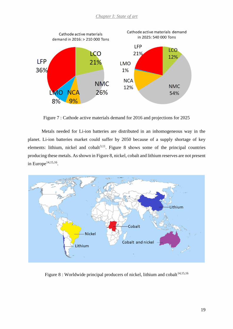
Metals needed for Li-ion batteries are distributed in an inhomogeneous way in the
planet. Li-ion batteries market could suffer by 2050 because of a supply shortage of key
elements: lithium, nickel and cobalt3,11. Figure 8 shows some of the principal countries
producing these metals. As shown in Figure 8, nickel, cobalt and lithium reserves are not present
in Europe14,15,16.
Figure 8 : Worldwide principal producers of nickel, lithium and cobalt14,15,16
Chapter I: State of art
20
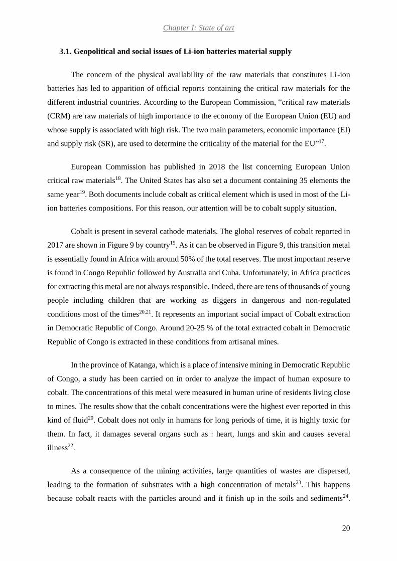
3.1. Geopolitical and social issues of Li-ion batteries material supply
The concern of the physical availability of the raw materials that constitutes Li-ion
batteries has led to apparition of official reports containing the critical raw materials for the
different industrial countries. According to the European Commission, “critical raw materials
(CRM) are raw materials of high importance to the economy of the European Union (EU) and
whose supply is associated with high risk. The two main parameters, economic importance (EI)
and supply risk (SR), are used to determine the criticality of the material for the EU”17.
European Commission has published in 2018 the list concerning European Union
critical raw materials18. The United States has also set a document containing 35 elements the
same year19. Both documents include cobalt as critical element which is used in most of the Li-
ion batteries compositions. For this reason, our attention will be to cobalt supply situation.
Cobalt is present in several cathode materials. The global reserves of cobalt reported in
2017 are shown in Figure 9 by country15. As it can be observed in Figure 9, this transition metal
is essentially found in Africa with around 50% of the total reserves. The most important reserve
is found in Congo Republic followed by Australia and Cuba. Unfortunately, in Africa practices
for extracting this metal are not always responsible. Indeed, there are tens of thousands of young
people including children that are working as diggers in dangerous and non-regulated
conditions most of the times20,21. It represents an important social impact of Cobalt extraction
in Democratic Republic of Congo. Around 20-25 % of the total extracted cobalt in Democratic
Republic of Congo is extracted in these conditions from artisanal mines.
In the province of Katanga, which is a place of intensive mining in Democratic Republic
of Congo, a study has been carried on in order to analyze the impact of human exposure to
cobalt. The concentrations of this metal were measured in human urine of residents living close
to mines. The results show that the cobalt concentrations were the highest ever reported in this
kind of fluid20. Cobalt does not only in humans for long periods of time, it is highly toxic for
them. In fact, it damages several organs such as : heart, lungs and skin and causes several
illness22.
As a consequence of the mining activities, large quantities of wastes are dispersed,
leading to the formation of substrates with a high concentration of metals23. This happens
because cobalt reacts with the particles around and it finish up in the soils and sediments24.

Chapter I: State of art
21
Battery manufacturers began to change cathode formulations from cobalt -rich materials to
nickel rich-ones due to the extraction conditions of cobalt in Africa3. Moreover, this initiative
is highly influenced by the instability of cobalt price in the last few years. Cobalt has quadrupled
its price in two years3 as shown in Figure 10.
Figure 9 : Cobalt Worldwide reserves reported in 2017
Figure 10 : Recent cobalt price evolution25

Chapter I: State of art
22
The increase in Li-ion batteries production has led to an important growth in the demand
of cobalt. This demand started to importantly increase in 2005 and this trend continues as shown
in Figure 11. By 2050, it is expected that more than 50% of the global cobalt production will
be needed only for rechargeable batteries manufacturing. Assuming the scenario in which the
actual cathode materials compositions will be present by 2025, only batteries are expected to
need more than 10% of global cobalt reserves by 2025 as shown in the Table 23.This assumption
considers also that all NMC used has the composition: LiNi1/3Mn1/3Co1/3O2 . Consequently,
there is a real concern about the supply of cobalt in the future.
Figure 11 : Cobalt demand projection for the rechargeable batteries 2000-202526

Chapter I: State of art
23
Table 2 : Projection of world battery material demand in 20253
Element Projected demand (kt) U.S Geological Survey (USGS)
reserves estimations (kt)
Lithium 230 16 000
Cobalt 910 7 100
Nickel 340 74 000
Regardless of the future cathode materials compositions, each year there are millions of
used batteries that need to be recycled. Burying them is not a long term viable alternative due
to their number and as they constitute a potential source of raw materials.
3.2. Recycling definition and its importance
Recycling has several definitions. It can be defined as making something new from
something that has already been used or to use something again. For this project, all the attention
will be focused on the waste recycling definition, which consists in any recovery operation by
which waste materials are reprocessed into products, materials or substances whether for the
original or other purposes.
Recycling of spent Li-ion batteries has become important because of several reasons.
Firstly, recycling contributes to reduce the wastes and all stages associated to their disposal.
Disposal can be expensive and polluting27. Using Li-ion batteries recycled materials contributes
to reduce some of the production impacts, including the ones linked to the mining of the ore,
the primary processing and the chemical processes of materials27. Figure 12 shows the battery
manufacturing process steps and how recycled materials can get in it at different stages. It can
be observed on Figure 12, that in the first stage the mining of the ore takes place. Once the
materials have been extracted, the primary processing takes place. This step is followed by the
chemical conversions and the battery fabrication. The manufactured battery is then used in the
electric vehicle. At the end of battery lifetime, it is recycled back to one of the manufacturing
stages. This happens sometimes directly after being used in electric vehicles. Other times,
batteries are reused for energy storage of an electric service before being recycled.
In fact, recycling is a positive alternative to lessen the huge demand for raw materials11.
Furthermore, recycling will enable to reduce the environmental concerns due to the toxic metals
present in this kind of batteries and cope with the depletion of material resources11. Having a
second resource of critical materials by recycling will enable to maintain market prices of these

Chapter I: State of art
24
elements more or less stable. Unfortunately, today only 5% of Li-ion batteries are recycled11.
Between 2017-2025, it is expected that the recycling market will raise around 30%11.
Figure 12 : Batteries recycled materials entering in the manufacturing process at different
stages27
Recycling can be considered as a source of raw constituents of batteries. From an
economic point of view, it is important to take into account the interval of time that exists
between the moment when the battery will be available to be recycled and its entrance in the
market. In the case of an electric vehicle battery, its lifetime is around 10 years3. This means
waiting at least ten years before recycling can provide a part of the raw material supply. As a
consequence, electrical vehicle batteries recycling will not be an immediate source of raw
materials. Nevertheless, the electric vehicles batteries constitute one of the most important
sources due to the high quantities of valuable materials in them, given by their sizes.

Chapter I: State of art
25
Electronic devices market uses nowadays a huge portion of the batteries production.
Generally, these kinds of devices contain batteries whose lifetime is of around 3 years3.
Recycling this kind of batteries will lead to a raw material supply in a relative short period of
time. Another source of raw material, which is available even in a better delay, is the one found
in the battery production scraps. In fact, this material will be directly accessible to be recycled
and its impact on the raw material supply will be seen immediately3.
Furthermore, the choice of the materials to be recycled is of great importance. It is
crucial to recover initially materials whose extraction from low-concentration ores is very
energy-guzzling3. Extraction also implies several environmental issues such as toxic gas
emissions. Recycling appears as an alternative to reduce this impact. An example of this can be
observed in Figure 13 for the sulfur oxide emissions in LCO production process3. As it is shown
in Figure 13, the quantity of sulfur oxides emitted by extraction process is at least twice the one
emitted by the recycling methods.
Figure 13 : Sulfur oxides emissions comparison between extraction and recycling methods for
producing LCO

Chapter I: State of art
26
3.3. Existing Li-ion batteries recycling methods
There are several methods that have been developed for Li-ion batteries recycling.
According to their feasibility, maturation state, cost-effectiveness, and environmental impacts
some of them have been chosen to be applied at industrial scales. The existing methods can be
classified in: pyrometallurgy, hydrometallurgy and direct recycling3. All the recycling methods
include a preliminary pretreatment step which is performed before metals recovery2.
3.3.1. Pretreatment
Pretreatment comprehends several steps that prepares the Li-ion battery and its materials
for recycling. The first stage consists in the sorting of batteries according to their type. Then,
batteries are deeply discharged, due to the residual power that remains in them at the end of
life2. This stage prevents the possible short-circuiting and self-ignition which can take place
because of a compressive shock or overheating respectively 28. Li-ion batteries are then
dismantled manually or mechanically to identify the battery composition and take off battery
plastic and metallic shells29. After dismantling, in some cases, the electrode materials from
current collector are separated by chemical or mechanical processes2,11.
3.3.2. Pyrometallurgy
The pyrometallurgy process consists in heating the elements of the battery, at a
temperature over 1000°C, in order to recover metal alloys11. The metal alloys contain basically
elements such as Co, Fe, Ni and Cu. Each one of these metals is then separated by leaching or
hydrometallurgy.
Aluminum and lithium are not achieved to be recovered and remain on the slag portion.
In order to provide heat to the process and reduce the transition metals, aluminum and all the
remaining organic compounds are oxidized3. The remaining slag containing lithium is sold to
the construction industries as a road base11. Even if this process enables a good recovery of a
good portion of metals, there are a big portion of the batteries constituents that is volatilized or
lost in the slag. This portion constitutes around 60-70% of the battery11.The volatilized products
are usually harmful gases and fluorine compounds. A big budget must be always planned to the
gas treatment3. The main advantage of this method is that it can treat batteries with different
cathode compositions.

Chapter I: State of art
27
3.3.3. Hydrometallurgy
This process consists in the dissolution of active materials in an aqueous solution and
then a selective recovery of its components by precipitation. For doing this, several acids, bases
or salts are used. The first stage, known as leaching, consists of dissolving the cathode active
material into an acidic solution at a temperature range between 30 to 90°C. To do this, strong
acids in a high concentration are used. HCl, HNO3 and H2SO4 are used in most of the cases30.
A reducing agent can be added to the acidic solution to facilitate the metal reduction in the
medium. The efficiency of this first step will depend on several parameters: the acid strength,
the acid concentration, the temperature and the concentration of the reducing agent30. For
example, some studies show the possibility of recovering several metals by using a mixture of
H2SO4 and H2O2 (as reducing agent) by the following reaction (Eq. 4)31:
2𝐿𝑖𝐶𝑜𝑂2 + 𝐻2𝑂2 + 3 𝐻2𝑆𝑂4 → 2𝐿𝑖+ + 2𝐶𝑜2+ + 3𝑆𝑂42− + 4𝐻2𝑂 + 𝑂2 (Eq. 4)
Once dissolution of the active materials has been achieved, an extraction step follows
for recovering the constituents of the active material. Usually, precipitation using a basic
solution is added to extract one by one the different constituents. Most of the time, NaOH is
used as base. The characteristics of the solution used (such as pH) will allow the selective
separation of metals32,30. Other approaches use the leaching solution as electrolyte for deposing
the dissolved active material33. Nowadays, numerous groups have focused their efforts in
optimizing hydrometallurgy approach.
As a consequence, innumerable researches, focused on reducing the environmental
impacts of the leaching step or improving the extraction step in the last few years. Concerning
the leaching step, many attempts have been done to substitute the strong and high concentrated
acids used at this stage by less hazardous agents. In this way, several alternatives have been
developed such as: ionic liquids mixed with acid solutions34,35, mild phosphoric acid36 , oxalic
acid37, citric acid38. Even biological approaches using bacteria such as: Acidithiobacillus
ferrooxidans39, Acidithiobacillus thiooxidans40 or Leptospirillum ferriphilum40 have been
developed for leaching. Other studies focus on improving the extraction stage. For example
precipitation method has been optimized by adding salts, in order to control the ratio of the
different metals in the solution41. This initiative leads to the recovery of hydroxides with the

Chapter I: State of art
28
form NixMnyCoz(OH)2 (x+y+z=1) that are directly used to synthesize active materials
LiNixMnyCozO241,42.
Hydrometallurgy shows the advantage of being not an energy-intensive method. Due to
the absence of high temperature heating, there are no direct carbon emissions from it41.
Nevertheless, it uses big volumes of effluents (acids or bases) during the process. The effluent
treatment is a delicate aspect that must be considered when using this process because it can
pollute environment.
3.3.4. Direct recovery
Some studies have been done in the recent years in order to develop a new alternative
approach for Li-ion batteries recycling: direct recovery. It consists in the relithiation of the spent
cathode materials by two kinds of processes: a liquid regeneration process and a solid-state
synthesis43. In the liquid process, spent cathode material regeneration is achieved in a basic
solution, generally constituted of LiOH, by hydrothermal treatment or by high-voltage power
applied to the solution43,44,45.The treated cathode powder is then washed to eliminate the lithium
excess, dried and annealed. The solid-state synthesis consists in mixing the spent cathode with
Li2CO3 for relithiating the material, followed by sintering of the obtained powder43,46. Before
mixing both materials together the mass contents of carbon, lithium and cobalt are measured
by Inductively coupled plasma (ICP) in order to calculate the exact quantity of Li2CO3 to have
a Li/Co ratio of 1.0546.
3.3.5. Principal recycling companies
There are several conditions to fulfill if we want to consider a process in an industrial
context. Firstly, the process should be eco-friendly by having a low environmental impact. It
should also be scalable to be used at an industrial scale. Finally, it should be cost-efficient and
be able to close the loop so that industrials find a profit to do it11. Moreover, recycling has to
be able to cope with the treatment of a variety of chemical compositions present in Li-ion
batteries.
Nowadays several companies are implied in the Li-ion batteries recycling to extract the
valuable metals in most of the cases. Many recycling companies are presented in Asia, North
America and Europe as shown in Table 342, 47. As observed on Table 3, pyrometallurgy and

Chapter I: State of art
29
hydrometallurgy methods are the only ones used in industrial processes42,47. Furthermore, they
can be sometimes combined.
Table 3 : Companies that recycle Li-ion batteries42,47
Company Process
classification
Annual
capacity (t) Country
GEM Hydrometallurgical 30 000 China
Guandong Brunp Recycling
Technology Co Ltd Hydrometallurgical 10 000 China
Fangyuan New Energy
Materials Hydrometallurgical 36 000 China
Tianqi Lithium Corp Hydrometallurgical - China
SungEel Hi Hydrometallurgical - South Korea
LG Chem Hydrometallurgical - South Korea
Retriev Technologies Hydrometallurgical 3500 United States
Umicore Pyrometallurgical +
Hydrometallurgical 7000 Belgium
Recupyl
Insolvent since 2018 Hydrometallurgical 110 France
Euro Dieuze Industrie Hydrometallurgical 6000 France
Xstrata Pyrometallurgical 3000 Switzerland
Batrec
Industrie
Mechanical
treatment
+Hydrometallurgical
1000 Switzerland
Accurec
Recycling GmbH Pyrometallurgical 1000 Germany
Duesenfeld Hydrometallurgical - Germany
Neometals Hydrometallurgical - Australia
There are other companies that dedicate some of their research and development
activities to Li-ion batteries recycling. This is the case of Eramet that is interested in lithium
recycling.
3.4. Legislative initiatives for facing the difficulties of recycling
Recycling is facing a big concern regarding one of the initial steps of the treatment:
batteries sorting. To optimize the recycling process, it is essential to separate Li-ion batteries
into different flows according to their chemical composition3. The real problem behind this
aspect is that batteries are not clearly identifiable according to their composition nowadays. To
try to solve this problem the Battery Recycling Committee of the Society of Automotive

Chapter I: State of art
30
Engineers (SAE) develop a label recommended to stuck on the battery’s pack by
manufacturers30. The label contains precious information about the battery system (Li-Ion, Pb-
Acid, NiMH, NiCd), the cathode elements (ex: Fe, Co, Mn, S, Ni, Al), the anode elements (ex:
C, Si, Ti, Sn, Li), the miscellaneous properties, the manufacturer ID (optional) and the
manufacture date48. Moreover, it could be read by humans and machines. This label is
completed by a color attribution to the label’s background according to the battery system. The
same color attribution has been adopted for the labels developed by the Battery Association of
Japan49. Figure 14 shows an example of label developed by SAE48. The essential information
which facilitates the recycling process and enables to consider the precautions needed, are
present in this label. If each battery manufacturer applies this recommendation, incidents could
also be prevented. For example, when a Li-ion battery gets into a Pb-acid batteries smelter, fire
and explosions can occur. It will also contribute to avoid the ignorance of dealing with
dangerous materials such as lead3. Other big difficulty for recycling Li-ion batteries comes from
the complexity of their cell’s composition and geometry. These cells contain many different
materials which are disposed in various geometries and sizes.
Figure 14 : Label for batteries identification developed by SAE, based on SAE J298448

Chapter I: State of art
31
4. Molten salts generalities
4.1. Definition, classification and properties
Molten salts or fused salts are non-aqueous solvents. In fact, they involve the ionic
compounds which are used at their molten state50. These liquid systems are well organized
over quite long distances, from the first shell of neighbors up to the nanometer length
scale51.This structure, which is less organized than the crystallized one, confers molten salts a
higher chemical mobility50.
Many organic and inorganic compounds can be dissolved in molten salts systems, some
of them in high concentrations. Furthermore, using molten salts enables to work in total absence
of water as solvent52. Moreover, thanks to the high temperatures used for this kind of systems,
chemical reactions occur fast and ions can adopt oxidation states which are unusual in other
media52. Other important characteristics of molten salts include: high thermal conductivity and
capacity, wide range of thermochemical stability, a good electrochemical stability, high
electrical conductivity5354. They show also very interesting transport properties such as: a
moderate viscosity and density which can enable an easy separation of the obtained products
from the medium52.
There are two kinds of molten salts: the neutralized and the oxidizing salts55. The
neutralized salts include alkali carbonates and halides55. The oxidizing salts include metal salts
of different types : nitrate, nitrite, sulfate, hydroxyl, metal oxides and chlorates55.
4.2. Examples of molten salts applications
The real origin of molten salts used is not clearly defined in history. From a popular
point of view, it is assumed that these media were firstly used when the glass industry appeared,
in ancient Phoenicia56. However, it is only in the nineteenth century that the molten salt
technology appeared concretely56. During this period of time, several remarkable discoveries
in this field took place. In 1807, Humphrey Davy discovered the possibility of separating alkali
metals from their hydroxides by electrolysis 57,58.Several years later in 1854, Deville developed
a process to obtain aluminum from the electrolysis of the molten mixture AlCl3-NaCl58. Later
in 1886, Paul Héroult, and Charles Hall discovered independently at the same time a cost-
efficient electrolytic process to produce aluminum. This process is still used nowadays and

Chapter I: State of art
32
consists in the reduction of molten aluminum oxide in molten cryolite59. This invention led to
the creation of several large-scale extraction plants. Later in 1921, Gerard Herman Jelke Broers
gave birth to a new discovery in fused salts field: molten carbonates fuel cells. Then, in the mid-
1940 army decide to support the molten salt research and development with the aim of
separating big amounts of uranium for the Manahattan project56. After the Second World War,
Alvin Weinberg achieved the creation of a molten salts reactor and adapted them to the civilian
power ones60. During the next decades, molten salts were developed in a broad horizon of
applications and technologies. In the next section, the major applications of these systems will
be discussed.
In order to give a general idea of the broad horizon of molten salts applications, the
applications have been classified according to the following areas: materials, energy and
recycling.
4.2.1. Materials synthesis and treatment
A variety of materials production has been developed in molten salt including: Non-
metallic materials and metals. Concerning non-metallic materials, carbonaceous materials are
obtained in molten salts for example. Nanopowders of carbons and amorphous carbon have
been synthesized in molten carbonates and molten fluorides respectively 61,62,63. These materials
can find applications in several fields such as fluorine production by electrolysis64 and as anodes
in rechargeable lithium-ion batteries65 .
Several metals manufacturing has been achieved in such media by electrolysis. This is
the case of aluminum, sodium and magnesium for example. Aluminum is produced in a molten
cryolite bath59 while magnesium and sodium are produced in different kind of melts such as:
chlorides, oxides and fluorides66,67,68,69. Refractory metals are also obtained by this mean.
Molten chlorides, fluorides or molten borates are frequently used for the manufacturing of
refractory metals like: molybdenum, tungsten, niobium and tantalum68,70. Metallic alloys as
well can be produced in molten medium. Nickel–tantalum alloys for example can be
manufactured by electrolysis in molten fluorides71.
Metal treatment processes can also be realized in molten salts. The possibility of
dissolving many organic and inorganic compounds in these media, make molten salts systems
really useful for metal treatment. Metals surface modification, protection, cleaning, finishing,

Chapter I: State of art
33
cementation and brazing can be done by this mean72,73. For example aluminum alloys’ surfaces
are treated in molten medium such as chlorides to prevent corrosion in sea water74. Other
examples are steel bluing and finishing which are done in molten nitrate-nitrite and molten-
cyanide-carbonate mixtures respectively72. Several other examples exist in the industrial world
but for a matter of time, they will not be detailed in this section.
4.2.2. Energy
Concerning energy production and storage, a great interest has been devoted to the
molten salts field. Molten salts reactors, molten carbonates fuel cells and molten salts
technologies for energy storage have appeared as a consequence. Concerning molten salts
reactors, they provide an alternative way to produce hydrogen or electricity compare to nuclear
steam suppliers75. Moreover they remain safe, sustainable, practical and stable systems 76,77.
Many advantages result from these types of reactors such as: the capability of producing fissile
fuel, burning actinides77.
Molten carbonates fuel cells have allowed generating 60 MW of stationary energy in
Korea50,53. This technology is able to produce both electricity and heat78. Concerning energy
storage applications there are two main molten salts technologies that have been developed:
inorganic molten salt electrolyte batteries and sensible heat storage systems. Molten salt
batteries contain molten chloroaluminate as electrolyte79. This kind of battery is generally used
in electric vehicles.
Molten salts have also played a crucial role in the retreatment of wastes and recycling.
Different kinds of wastes have been studied in this medium in order to develop a decomposition
or a recovery process. For example, oxidizing of wastes in molten salts systems such as alkali
carbonates appear as an alternative to wastes incineration. In this way, hazardous organic
compounds such as cyanides can be trapped in the molten system80.
4.2.3. Recycling
Recycling of inorganic wastes in molten salts (Molten Salts Oxidation or MSO) such as
black liquor, coming from kraft pulping process, lead to the production of sodium oxide and
sodium sulfide, which can then be used in other applications81. Other studies have focused on
the recovery of different metals, some of them critical for the European Union. In this context,
copper-rich compounds have been retrieved from electronic wastes82, after being separated

Chapter I: State of art
34
from non-metallic components such as fiberglass, epoxy resin and plastics in molten
hydroxides82 or alkali carbonates55. By this way, other precious metals such as nickel, gold and
silver can also be recovered82. Furthermore, most of the organic compounds were trapped in
the bath and the rest decomposed in essentially hydrogen 82.
Irradiated nuclear fuel wastes processing has been developed in several countries, using
different systems of molten salts such as fluorides and chlorides 83,84. These kinds of retreatment
sometimes include a electrorefining step which enables the production of high purity uranium,
used for power generation 84,85. Uranium is in this way separated from a mixture of: plutonium,
americium, curium, neptunium, cadmium and some rare-earth fission products84. Other studies
show the possibility of applying oxidizing salts like alkali carbonates, which allow the
separation of uranium and plutonium from the spent fuel in the form of salts86,87. Other studies
focused on the retrieving of rare-earth elements from the remaining portion of fission products.
For example, some rare earth elements (La, Ce, Pr, Eu, Tb, Dy, Nd, Pm, Sm) have been reported
to be recovered as phosphates in a molten chlorides-phosphates mixture86,87. Other lanthanides
elements such as gadolinium can be extracted in molten fluorides mixtures88.
As described, molten salts show plenty of applications in different industrial fields. The
aim of this section is to give an idea as exhaustive as possible of the vast world of applications.
According to the application, one or several molten salts families will fulfill the properties
required to achieve the desire objective.
4.3. Choice of molten salts systems
The objective of this project is to study the possibility of recycling Li-ion battery organic
and inorganic compounds in one molten salt system. Concerning the inorganic compounds, in
the context of this study, the attention will be specially attached to the cobalt recovery. As
observed in this chapter, cobalt shows the most critical situation (social, economic and
environmental issues). Two types of molten salts systems seem to be adapted for this study:
molten carbonates and molten chlorides.
To start with, molten carbonates are well known for their capacity to decompose organic
compounds (as seen in section 3.3), which can be very useful for treating Li-ion battery organic
ones. Secondly, molten chlorides show very attractive characteristics for dissolving metal
oxides (as seen in section 3.3). Furthermore, they constitute reaction medium in which a vast

Chapter I: State of art
35
diversity of metals is produced by electrolysis (as seen in section 3.3). These reasons make
molten chlorides a very interesting medium for studying the possibility of recovering Li-ion
batteries cobalt from cathode materials.
4.3.1. Physico-chemical properties of alkali carbonates
The most important alkali carbonates are: Li2CO3, Na2CO3 and K2CO3. These
compounds are interesting reaction medium due to their physico-chemical properties. They are
stables in the range between 400 and 1000 °C 89. Furthermore, they are characterized by a low
vapor pressure89. Alkaline carbonates melt at high temperatures, when they are used in a single
salt system. Nevertheless, when they are used in eutectic mixtures, alkaline carbonates melt at
lower temperatures. Table 4 shows some other properties: composition, molar weight, and
melting point54,90.
Table 4 : Properties of the principal molten alkaline carbonates and their eutectic mixtures54,90
Carbonates mixtures
Composition (molar %)
Li2CO3 Na2CO3 K2CO3
Molar weight
(g. mol-1)
Melting point
(°C)
K2CO3 0 0 100 138.2 899
Na2CO3 0 100 0 106 858
Li2CO3 100 0 0 73.9 726
Na2CO3-K2CO3 0 56 44 120.2 710
Li2CO3-K2CO3 42.7 0 57.3 110.7 498
Li2CO3-Na2CO3 62 0 38 98.3 488
Li2CO3-Na2CO3-
K2CO3 43.5 31.5 25 100.1 397
4.3.1.1. Oxoacidity of carbonates
As for the aqueous systems, acido-basicity concept also applies to molten salts. In an
aqueous medium, this notion is defined by the theory of Lowry-Brönsted, where a proton is
given by an acid (or proton donor) and received by a base (or proton acceptor). In the molten
salts systems, the acidity is defined by the Lux-Flood theory. By contrast, the oxobase is defined
as the donor of an oxide anion (O2-) and the oxoacid as the acceptor91. The reaction between
the oxoacid and the oxobase is given by the following equation (Eq. 5):

Chapter I: State of art
36
𝑜𝑥𝑜𝑏𝑎𝑠𝑒 = 𝑜𝑥𝑜𝑎𝑐𝑖𝑑 + 𝑂2− (Eq. 5)
By this way, in the case of molten carbonates, the oxobase is the carbonate ion and its
reaction with the oxoacid is given by (Eq. 6):
𝐶𝑂32− ↔ 𝐶𝑂2 + 𝑂2− (Eq. 6)
From this reaction the level of oxoacidity in a molten carbonate medium is defined by
the equation (Eq. 7):
𝑝𝑂2− = −log [𝑎(𝑂2−)] (Eq. 7)
Where a(O2-) is the activity of O2-. Therefore, the increase of pO2- rise the oxoacidity
level.
The reaction of self-ionization or decomposition of a molten carbonate can be then
expressed by (Eq. 8):
𝑀2𝐶𝑂3(𝑙) → 𝐶𝑂2(𝑔) + 𝑀2𝑂(𝑠) (Eq. 8)
Where M is the alkaline ion (Li, Na, K), (l), (s) and (g) represent the liquid, solid and
gas phases respectively. This equilibrium is characterized by the following equilibrium constant
(Eq. 9):
𝐾∗ =𝑎(𝑀2𝑂)𝑃(𝐶𝑂2)
𝑎(𝑀2𝐶𝑂3) (Eq. 9)
Where 𝑎(𝑀2𝑂) is the activity of the oxide, 𝑎(𝑀2𝐶𝑂3) the activity of the carbonate, and
P(CO2) the CO2 vapor pressure.
4.3.1.1.1. Case of a single carbonate
In the case of a single carbonate, the activity of the molten carbonate in the self-
ionization equilibrium is equal to 1. Some studies in molten carbonates show that in the case of

Chapter I: State of art
37
alkali carbonates, at the same fixed temperature, the dissociation constants show the following
relation (Eq. 10)92,93:
𝑝𝐾∗(𝐿𝑖2𝐶𝑂3) < 𝑝𝐾∗(𝑁𝑎2𝐶𝑂3) < 𝑝𝐾∗(𝐾2𝐶𝑂3) (Eq. 10)
Molten carbonates are used in the form of eutectic mixtures composed of at least two
constituents because of their lower melting point compared to a single salt system.
4.3.1.1.2. Case of a mixture of several molten carbonates
In a mixture of several carbonates, the self-ionization equilibrium is given by the
formation of the less soluble oxide, which sets the basic limit in the oxoacidity range of the
system. The acid limit is given by highest pressure of CO2 that is of 1 atmosphere. For alkali
carbonates the self-ionization reactions are given by the following reactions (Eq. 11), (Eq. 12)
and (Eq. 13):
𝐿𝑖2𝐶𝑂3(𝑙) → 𝐿𝑖2𝑂(𝑠) + 𝐶𝑂2(𝑔) (Eq. 11)
𝑁𝑎2𝐶𝑂3(𝑙) → 𝑁𝑎2𝑂(𝑠) + 𝐶𝑂2(𝑔) (Eq. 12)
𝐾2𝐶𝑂3(𝑙) → 𝐾2𝑂(𝑠) + 𝐶𝑂2(𝑔) (Eq. 13)
In the case of a mixture of molten carbonates, the activity of the molten carbonate is not
equal to 1. In this case the self-ionization constant K* becomes 𝐾𝑑∗ and is defined by the
following relation (Eq. 14):
𝐾𝑑∗ = 𝑎(𝑀2𝑂)𝑃(𝐶𝑂2) = 𝐾∗𝑎(𝑀2𝐶𝑂3) (Eq. 14)
The stability order for alkali oxides is the following: Li2O > Na2O > K2O. Consequently,
for the mixtures Li2CO3-K2CO3, Li2CO3-Na2CO3 and the ternary mixture made of Li2CO3-
Na2CO3-K2CO3, lithium oxide will be the first to precipitate while in the case of the mixtures
constituted of Na2CO3-K2CO3, sodium oxide will be the first one.

Chapter I: State of art
38
4.3.2. Physico-chemical properties of molten alkali chlorides
As for alkali molten carbonates, the most important molten alkali chlorides are: LiCl,
KCl and NaCl. Table 5 shows the principal melts used with some of their properties:
composition, molar weight and melting point, organized from the highest melting point to the
lowest one54,94,95.
Table 5 : Properties of the principal molten alkaline chlorides and their eutectic mixtures54,94,95
Carbonates
mixtures
Composition (molar %)
LiCl KCl NaCl
Molar weight
(g. mol-1)
Melting
point (°C)
NaCl 0 0 100 58.44 808
KCl 0 100 0 74.56 770
NaCl-KCl 0 50 50 66.5 658
LiCl 100 0 0 42.39 610
LiCl-NaCl 65.58 34.42 0 47.91 554
LiCl-KCl-NaCl 43 24 33 55.40 357
LiCl-KCl 55.7 44.3 0 56.64 355
4.3.2.1. Chloroacidity of chlorides
The analogue concept of oxoacidity exists for molten chlorides: chloroacidity.
Chloroacid is defined as the acceptor of a chloride anion (Cl-) and a chlorobase as the donor96.
The reaction given by the chlorobase and the chloroacid is given by the following equation (Eq.
15):
𝑐ℎ𝑙𝑜𝑟𝑜𝑏𝑎𝑠𝑒 = 𝑐ℎ𝑙𝑜𝑟𝑜𝑎𝑐𝑖𝑑 + 𝐶𝑙− (Eq. 15)
For example LiCl is a chlorobase and its reaction is given by (Eq. 16):
𝐿𝑖𝐶𝑙 ↔ 𝐿𝑖+ + 𝐶𝑙− (Eq. 16)
The chloroacidity of the molten chloride medium is defined by the equation (Eq. 17):
𝑝𝐶𝑙− = −log [𝑎(𝐶𝑙−)] (Eq. 17)
Where a(Cl-) is the activity of Cl-. Therefore, the increase of pCl- rises the chloroacidity
level.

Chapter I: State of art
39
4.3.2.2. Metal oxides dissolution in molten chlorides
Molten chlorides are known for having a good capacity to solubilize metallic cations of
oxides. This property has led to the possibility of producing several metals by electrolysis from
their oxides such as: Ti97, Ta98, Nb98, Ce99. To do it, two different kinds of processes have been
developed around the year 2000: Fray, Farthing and Chen (FFC) process (or direct reduction)97
; and Ono and Suzuki (OS) process (or indirect reduction)100 of the oxide. Both processes were
initially developed for titanium production and then applied to other metal manufacturing in
molten chlorides. The case of titanium manufacturing in molten CaCl2 is used as an example
for explaining the reaction mechanisms taking place at the cathode for each case:
FFC process or direct reduction process (Eq. 18)97:
𝑇𝑖𝑂𝑥 + 2𝑥𝑒− ↔ 𝑇𝑖 + 𝑥𝑂2− (Eq. 18)
OS process or indirect reduction process (Eq. 19) and (Eq. 20) 100:
𝐶𝑎2+ + 2𝑒− → 𝐶𝑎 (Eq. 19)
𝑥𝐶𝑎 + 𝑇𝑖𝑂𝑥 → 𝑇𝑖 + 𝑥𝐶𝑎2+ + 𝑥𝑂2− (Eq. 20)
5. Strategy
In the first place, some battery organic compounds decomposition will be studied in
molten carbonates. Then Li-ion cathodes behavior in eutectic molten Li2CO3-K2CO3-Na2CO3
carbonates will be studied by electrochemical techniques, in order to explore the possibility of
recovering cobalt by electrodeposition. The success of this method depends on the cobalt
solubility in the molten carbonates medium and the electrode material choice.
In the second place, Li-ion cathode material behavior in eutectic molten LiCl-KCl
chlorides will be studied by electrochemical techniques, in order to recover it by
electrodeposition. As for carbonates, cobalt solubility in the molten medium and the electrode
material choice will be discussed in order to facilitate cobalt electrodeposition.
Chapter II: Study of Li-ion battery compounds in molten
salts by X-ray absorption spectroscopy
“Premier principe : ne jamais se
laisser abattre par des personnes
ou par des événements.”
Marie Curie

Chapter II: Study of Li-ion battery compounds in molten salts by X-ray absorption
spectroscopy
41
1. Introduction
In the context of exploring the possibility of recycling cobalt by electrolysis from
eutectic Li2CO3-Na2CO3-K2CO3 several questions show up: what happens to cobalt from
cathode materials once it is in the melt? Which is its speciation? Does its oxidation state change
in the medium? How does it interact with the electrode during the electrolysis? Which is the
reaction taking place at the electrode? Answering these questions is essential to determine if
the choice of the molten solvent and electrode are appropriate or not. Furthermore, with the
knowledge of the oxidation state of cobalt in the molten system, it is possible to quantify its
solubility in medium by electrochemical techniques.
The objective of this chapter is the study of cobalt in molten carbonates (liquids) during
the electrolysis by X-ray absorption spectroscopy (XAS). XAS has been chosen for this study
face to other techniques because it is a powerful analytical tool, that enables to characterize the
local atomic order in any material (crystal, amorphous, liquids, polymers,..) contrary to XRD
which can be done only on crystalline solids. This technique gives information on interatomic
distances, nature and coordination of the neighbors surrounding the absorbing atom and
oxidation state of the studied element. X-ray spectroscopy shows numerous advantages. In fact,
it can characterize material at particular experimental conditions of : vacuum, controlled
atmosphere, pressure, high temperatures (around 1200 °C), diluted samples, in situ reactions
with a time resolution < 1s101. In addition, the selectivity of this technique allows us to study
each element in the sample separately. In the context of our study, XAS is the only available
technique that enable us to determine cobalt speciation and oxidation state in a liquid at high
temperature (> 500°C).
This project implies a major challenge: creating an entire device (molten salt container
heating system and electrochemical set-up) adapted to synchrotron facilities. This involves
several difficulties. In fact, the device materials must ensure the sample’s sealing, heating
temperature stability and good contact between the sample and the electrodes. Furthermore, the
chosen materials must ensure the good transmission of the beam, and cope with high
temperatures of about 600 °C for long periods of time (several days) to be used for the several
experiments. During this project we deal with a supplementary difficulty which concerns the
cobalt XAS measurements, because its binding energy is close to potassium one, which is one

Chapter II: Study of Li-ion battery compounds in molten salts by X-ray absorption
spectroscopy
42
of the constituents of the molten solvent. One by one these technical constraints have been
overcome in our team and the results are presented in this chapter.
1.1. X-ray absorption spectroscopy (XAS) technique
The principle of interaction of X-rays with matter
X-rays are electromagnetic radiations that show different interactions with the matter:
inelastic and elastic scattering, and photoelectric effect. XAS relies on this last one, where the
absorption of a photon causes the ejection of an electron from a core shell level of the absorbing
atom and is followed by a photoelectron emission. The electron is promoted to a final state that
can be a bounded or unbounded. The final state depends on the energy of the absorbed photon
and the binding energy as given in the following relation102:
𝐸𝑓 = ħ𝜔 − 𝐸0 (Eq. 21)
Where:
Ef: the final level energy
E0: the binding energy
ħω: the absorbed photon energy
The absorption is measured by scanning a range of X-ray energies which includes the
binding energy of core shell electrons of the studied element. The absorption of X-ray is defined
by Beer-Lambert’s law according to the following relation102:
𝐼 = 𝐼0𝑒−µ𝑥 (Eq. 22)
Where:
I: the intensity transmitted through the sample
I0: the X-ray intensity incident on a sample
x: the sample thickness
µ: the absorption coefficient which gives the probability that X-rays will be absorbed
The absorption spectrum is divided into two main regions, as shown on Figure 15:
EXAFS (Extended X-ray Absorption Fine Structure) and XANES (X-ray Absorption Near
Edge Structure). This distinction between both regions is arbitrary as there is not a clear
definition that distinguishes the near-edge and extended structure.

Chapter II: Study of Li-ion battery compounds in molten salts by X-ray absorption
spectroscopy
43
Figure 15: Co K-edge absorption spectrum of LiCoO2
At the edge (where Ef = E0) the contributions observed correspond still to bounded
resonances103. But above this value of energy, the final state belongs to the continuum spectrum.
In this case, a photoelectron escapes from the absorbing atom and its energy is defined by the
following equation:
𝐸𝑓 = ħ𝜔 − 𝐸0 =ħ2𝑘2
2𝑚 (Eq. 23)
Where:
k: the photoelectron wavevector
m: the electron mass
The emitted photoelectron probes its local environment. Its wave is scattered from the
photoabsorbing atom to another atom at a distance photoabsorber-scatterer (Ras in Figure 16)
and then returns to the absorbing atom (Figure 16). The photon electron wave travels a total
distance of 2Ras to complete a round trip. The final-state wavefunction at the absorber is
modified by the back-scattered wave and results in a quantum interference effect; that is visible
as an oscillation of the absorption as function of the photon energy. This phenomenon is known
as extended X-ray absorption fine structure (EXAFS)103. This region generally includes the
oscillations above the edge with a range generally of 40-1000 eV. The frequency of these

Chapter II: Study of Li-ion battery compounds in molten salts by X-ray absorption
spectroscopy
44
oscillations is correlated to interatomic distances between the photoabsorber and the
neighboring atoms. Their amplitude depends on the nature and number of surrounding atoms,
the thermal and structural disorder of the system.
Figure 16 : Atom A emitted a photoelectron which is back-scattered by the scattering atom
S104
The EXAFS signal is defined by the following equation:
𝜒(𝑘) = ∑𝑁𝑗
𝑘𝑅𝑗2 𝑒−2𝑅𝑗/𝜆𝑗(𝑘)|𝑓𝑗(𝑘, 𝜋)|
𝑗
sin (2𝑘𝑅𝑗 + 2𝛿𝑙′(𝑘) + ∅𝑗(𝑘))𝑒−2𝜎𝑗2𝑘2
(Eq. 24)
Where:
|𝑓𝑗(𝑘, 𝜋)|: the backscattering amplitude of neighbors j
∅𝑗(𝑘): the phase function of neighbors j
𝛿𝑙′(𝑘): l = 1 phaseshift for the photoabsorber atom
𝜆𝑗(𝑘): the phenomenological mean-free-path accounting for inelastic losses
𝑅𝑗: distance photoabsorber-neighbor j
𝑒−2𝜎𝑗2𝑘2: EXAFS Debye-Waller factor
EXAFS can also be defined as function of the absorption coefficient µ(E) by equation
25:
𝜒(𝐸) =µ(𝐸) − µ0(𝐸)
µ0(𝐸) (Eq. 25)

Chapter II: Study of Li-ion battery compounds in molten salts by X-ray absorption
spectroscopy
45
Where:
E: the photon energy
µ(E): the measured absorption coefficient
µ0(E): the smooth background function representing the absorption of an isolated atom
Concerning XANES, it corresponds to the part of the spectrum in the vicinity of the
edge. This region is of great interest in our case as it gives the information about the oxidation
state of the absorbing atom. The energy of the edge is not well defined as it is usually considered
as the energy corresponding to the inflexion point (half height), also known as the maximum of
the first derivative with respect to the energy. This energy is essential to determine the oxidation
state of the absorbing element. Edge energy increases when the oxidation state increases. This
is explained by the fact that more energetic X-rays are needed to eject an electron of atoms with
a higher oxidation state as they have a higher charge.
Transmission XAS measurements
There are different types of XAS measurements: fluorescence, polarized and
transmission. This last mode was used for our study. Figure 17 shows the typical apparatus for
transmission XAS measurements102.
Figure 17 : Schema of the typical equipment for transmission XAS measurement104
In this case, X-ray beam’s intensity is measured before and after the sample. The absorption
coefficient µ is calculated by (Eq. 22). Ionization detectors, which consist in a chamber filled
with a gas or a gas mixture, is used to measure X-ray intensity. Two detectors are positioned
along the beam axis, in front of and behind the sample. A third one is usually added on the same
axis for XAS measurement of a standard after the sample. The spectrum obtained from the
standard is used to calibrate the energy scale with a known one.

Chapter II: Study of Li-ion battery compounds in molten salts by X-ray absorption
spectroscopy
46
2. Results and discussion
2.1. Developing a new device for in situ XAS measurements in molten salts
As mentioned before the objective of our study is to monitor cobalt behavior in molten
carbonates during the electrolysis by XAS. Several challenges and requirements appear in the
conception of the device for the measurements. Firstly, a cell constituted of a material with the
minimum X-ray absorption between 7 keV and 8 keV (Co-K edge) was needed. The same
condition was unavoidable for the heating system. Both set-up parts must show a thermal
resistance up to 600°C. Kapton which is usually used as sample container cannot be used as it
does not resist temperature over 400°C.
The cell material must not react with the molten mixture (molten carbonates + cobalt
precursor). Furthermore, a perfect contact must be ensured between the electrodes and the
sample. Once the salts melt, there is supplementary difficulty that appears: ensuring the
homogenous distribution and filling of the molten mixture in the cell for the XAS and
electrochemical measurements. Finally, studying cobalt in the eutectic Li2CO3-Na2CO3-K2CO3
implies a supplementary challenge as the absorption energies of potassium and cobalt are close.
In this way potassium absorb part of the photons dedicated for cobalt characterization.
Only few studies reported the use of XAS for molten salts characterization at high
temperature due to the peculiar technical difficulties that it involves. Some devices for in situ
XAS measurements of molten salts have already been reported in the literature as shown on
Figure 18. We analyzed one by one the proposed devices and inspire ourselves from them to
create our set-up.
According to the type of molten salt and the experimental conditions, the designs of
them have been adapted. In this way Mikkelsen, J. C. et al, have developed a boron nitride or
graphite cell that can be used for the molten materials such as molten chlorides and solids up to
1000 °C105. The idea of using graphite for the salt container for our set-up seems a suitable
alternative as it shows a good stability to temperature (in the absence of oxygen), low absorption
compared to cobalt and it is a relatively cheap material. Two parts composed the Mikkelsen J.
C et al set-up: the screw-together holder and the sample containing insert (Figure 18 (a)).
Ensuring the sealing of the sample seems to be delicate as the set-up is closed only by two
points as seen on Figure 18 (a), and no proof of the set-up reliability has been shown.

Chapter II: Study of Li-ion battery compounds in molten salts by X-ray absorption
spectroscopy
47
Filipponi A. et al. proposed another set-up for studying molten bromides or metals up
to 3000 K under vacuum, which is also constituted of graphite106,107. The set-up is constituted
by the sample container (graphite crucible) and a glass vessel as shown in Figure 18 (b). The
sample container is tight to two stainless-steel cylindrical bars which work as electric
conductors, providing the heating to the graphite crucible. As our final objective is to carry out
electrochemical measurements, a direct contact between the sample container and the electric
conductors must be avoided. For this reason, this set-up design is not suitable for our project.
Figure 18 : Mikkelsen J.C. et al. sample cell showing the screw- together two-part holder and
the sample-containing insert made of boron nitride or graphite (a). (b) shows Filipponi A. et al
set-up, where A is the glass external container, B are Kapton windows, C the glass inlet for
gases, D and E are Teflon covers, F Vyton O-ring, G are the electric conductors, H
feedthrough for thermocouple, J is the planar graphite crucible. (c) shows Okamoto Y. et al
set-up. Rollet A-L. et al. two-plate cell in pyrolytic boron nitride which is closed by stainless
steel screws (d).

Chapter II: Study of Li-ion battery compounds in molten salts by X-ray absorption
spectroscopy
48
Lauday et al, proposed a contactless device for the measuring molten alumina up to
2500 °C108. This is possible thanks to an aerodynamic boron nitride levitator. This set-up is not
adapted to our experiments as we need a cell container to prevent vaporization and composition
evolution during measurement and also to install all the electrochemical elements.
Okamoto, Y. et al, proposed a quartz cell for measuring molten chlorides solvents
containing lanthanum109 (set-up device on Figure 18 (c)). The quartz cell has a sandglass form.
This cell form can be used for our experiment, as it guarantees the complete filling of the cell
section where the beam goes through, once the sample is melted. Quartz shows a good stability
to high temperatures (about 1000 °C) but it has a higher absorption than graphite. For this
reason, we did not consider the possibility of using this material for our set-up. Furthermore,
the pasting of the electrodes on this material can be complicate. Finally, Rollet et al, developed
a pyrolytic boron nitride cell to study lanthanide in molten fluorides (Figure 18 (d)) 110. As there
might exist an interaction between boron nitride and the melt (carbonates + cobalt), we decide
not to consider this material as an option. Furthermore, this set-up design was not suitable for
our study as electrodes could not be added on it for a matter of space.
Among all the cell materials used for salt container manufacturing in literature, we chose
graphite, already used for the sample container by Mikkelsen et al105; Filipponi et al 106.
Graphite was selected for its good stability to the high temperatures (in the absence of oxygen)
and because it is cheap. Furthermore, we opt for using Okamoto et al’s109 cell form (sandglass)
as it enables to ensure the total filling of the cell for the measurement, once that the salt melts.
As a first step, we developed the set-up and tested it for cobalt study in molten carbonates
without electrochemical measurements. The development of this device is shown in the next
section.
2.1.1. Sample container and sample thickness
To meet the sample container or cell requirements mentioned before, quartz used by
Okamoto et al109 for mixtures of molten chlorides and lanthanides shows a too high absorbance
with respect to cobalt absorption. Besides, using pyrolytic boron nitride material is not either a
suitable candidate as there might be an interaction between the molten carbonate and it. As a
consequence, both reported set-ups materials cannot be used.
Graphite and glassy carbon appear to be good alternatives as both have been already been used
in reported studies of molten carbonates without problems61. Moreover, graphite shows the

Chapter II: Study of Li-ion battery compounds in molten salts by X-ray absorption
spectroscopy
49
qualities of absorbing X-ray in low level and being easily machining. Nevertheless, a thin grain
quality is indispensable to manufacture thin cell’s walls. Furthermore, graphite possesses an
optimal resistance to very high temperatures and under thermal stress it does not deform, burst
or shrink. Lastly, it is stable in corrosive environments. For all these reasons, the graphite R6710
from Final Materials has been chosen as sample container material.
Sample and container thicknesses are important in order to optimize the X-ray
transmitted through the sample. The probability of X-ray to be absorbed by the sample and the
cell can be checked through Beer-Lambert’s Law (Eq. 22).
The maximal absorption was found when the cell was 200 µm thick. Inspiring from
Okamoto setting approach, we achieve to the design shown on Figure 19. A cavity of 300 or
400 µm thick was done. Above it, a reservoir was built to ensure the complete filling of the
cavity when the salt was melted. Both of them were filled with the solid sample. Machining
graphite with a low thickness with the available laboratory tools was one the greatest challenges
in the manufacturing of the cell. For these reasons, we make thicker (300 µm) the wall for part
A and a complete hole for part C on Figure 19. This counterpart of the cell (C) was combined
with a very thin glassy carbon sheet, with thicknesses of 60 or 100 µm.
To ensure the total and optimal filling of the cell, we decide to put the maximum amount
of salt in by the pellet method. Pellets were composed of salt grinded for at least 10 minutes
and then pressed with 5 tons pressure at room atmosphere. Pellets have the exact cavity’s
thickness and were set into the cell’s cavity and reservoir in the same atmosphere conditions.
Then the empty space was filled with salt powder. Finally, the three parts A, B and C were fixed
together with graphite glue form Final Materials.
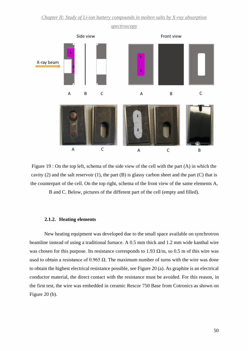
Chapter II: Study of Li-ion battery compounds in molten salts by X-ray absorption
spectroscopy
50
Figure 19 : On the top left, schema of the side view of the cell with the part (A) in which the
cavity (2) and the salt reservoir (1), the part (B) is glassy carbon sheet and the part (C) that is
the counterpart of the cell. On the top right, schema of the front view of the same elements A,
B and C. Below, pictures of the different part of the cell (empty and filled).
2.1.2. Heating elements
New heating equipment was developed due to the small space available on synchrotron
beamline instead of using a traditional furnace. A 0.5 mm thick and 1.2 mm wide kanthal wire
was chosen for this purpose. Its resistance corresponds to 1.93 Ω/m, so 0.5 m of this wire was
used to obtain a resistance of 0.965 Ω. The maximum number of turns with the wire was done
to obtain the highest electrical resistance possible, see Figure 20 (a). As graphite is an electrical
conductor material, the direct contact with the resistance must be avoided. For this reason, in
the first test, the wire was embedded in ceramic Rescor 750 Base from Cotronics as shown on
Figure 20 (b).

Chapter II: Study of Li-ion battery compounds in molten salts by X-ray absorption
spectroscopy
51
Figure 20 : Picture (A) shows the resistance, Picture (B) shows the resistance in ceramic,
picture (C) shows the heating sandwich where (a) is the inox plate coated with ceramic, (b )
and (d )are Boron Nitride plates, and (c) the resistance
With this initial idea, the heating of cell up to 400 °C was achieved, but with no stability.
In fact, a temperature oscillation higher than ± 20°C was present due to a bad contact between
the heating system and the cell. In a second attempt, the cell was coated with high purity alumina
ceramic (Resbond 989F from Final Materials). The coated cell was in contact with the
resistance through an inox plate coated with the same ceramic. With this heating material, 600
°C could be reached with a stability of ± 2°C and a maximum ramp of 20 °C/min. However,
this heating system cannot be used to perform several experiments as the coating was very
fragile after the first heating. In the third test and final one, the resistance (c on Figure 20(c))
was sandwiched between 2 Boron Nitride plates (b and d) as shown on Figure 20 (c). This
material was chosen for its properties of good electrical isolation, thermal conductivity and easy
machining. This last heating set-up fulfilled all the requirements of temperature stability and
robustness to being used for several experiments. A hole was drilled on each plate to allow the
beam pass through.
2.1.3. The chamber
A ceramic chamber has been built around the heating system in order to ensure the
thermal insulation during the heat (a on Figure 21). Three types of ceramic were tested for the
chamber: Durapot 804 powder, Rescore 750 base precision castable ceramic and Resbond 989F
high-purity alumina ceramic. The first two were very fragile and do not resist even the low
thermal test as they can handle up to a temperature of 400 °C only. The last one possesses the

Chapter II: Study of Li-ion battery compounds in molten salts by X-ray absorption
spectroscopy
52
thermal stability required to be used. The chamber was constituted by several pieces fabricated
separately and then assembled with ceramic glue (Final Materials).
To protect and isolate the whole system, we enclosed it in an aluminum chamber (c on
Figure 21). This chamber has a height of 127 mm and a hole on two parallel sides to allow the
beam to pass through (b on Figure 21). Both holes were covered by Kapton to ensure the total
closing of the system. To monitor the temperature of the molten system with a thermocouple, a
hole on the graphite cell and on both chambers was made.
Figure 21 : (a): graphite cell, (b): the window for beam passage, (c): aluminum stand
2.1.4. Experimental conditions for in situ measurements
Atmosphere
To avoid the entrance of oxygen from the atmosphere into the chamber, an inert vector
gas was used. The first reason involves the possible reaction between cobalt from the sample
and oxygen. The second one implies graphite burning in presence of oxygen at high
temperatures. The vector gas chosen must have a high thermal conductivity and no oxygen.

Chapter II: Study of Li-ion battery compounds in molten salts by X-ray absorption
spectroscopy
53
Helium and nitrogen appear to fulfill these requirements. For simplicity we chose nitrogen. A
hole was added to both chambers (ceramic and aluminum) to allow the entrance of gas.
Synchrotron experimental conditions
X-ray absorption spectroscopy measurements at Co K-edge (7709 eV) were performed
in transmission mode at ROCK (Rocking Optics for Chemical Kinetics) beamline of SOLEIL
Synchrotron facilities111. This beam line is dedicated to material science and high temperature
studies combining X-ray diffraction and absorption in a tunable energy range (4-40 keV).
ROCK beam line enables to carry out quick experiments and by the way monitoring fast
kinetic processes. For this reason, we chose this line for our experiments. The monochromated
X-ray beam focused on the sample, has the dimensions: 80 µm x 350 µm. The requested energy
range was of 7300-8500 eV. Cobalt metallic foil was used as reference of energy for each
measurement.
Heating conditions
The samples were heated up with a ramp of 10°C/min. We increased the temperature
stepwise (350 °C, 450 °C and 550 °C). The temperature stability at each plateau was achieved
at about 2-3 minutes. This was detected by the observation of a stability of the transmitted
intensity. In this condition, the absorption spectrum was recorded. After the last plateau at 550
°C, the system’s temperature decreased in a steady way.
Samples
The samples used for all the experiments in this chapter come from molten baths already
used for electrochemical studies (all of them are presented in chapter III). For each case, we
heated in the cell at synchrotron facilities only a portion of the homogenous purple zone. For
all of them Li2CO3-Na2CO3-K2CO3 eutectic mixture was used as solvent. For the experimental
details about the preparation of these molten systems see experimental section in chapter III.
Reference compounds
The following list of compounds has been used as references as they have a known
oxidation cobalt state as shown on Table 6. Each reference compound powder was mixed with
Boron Nitride, then grinded and pressed with 5 tons for about 3 minutes to make a pellet. The
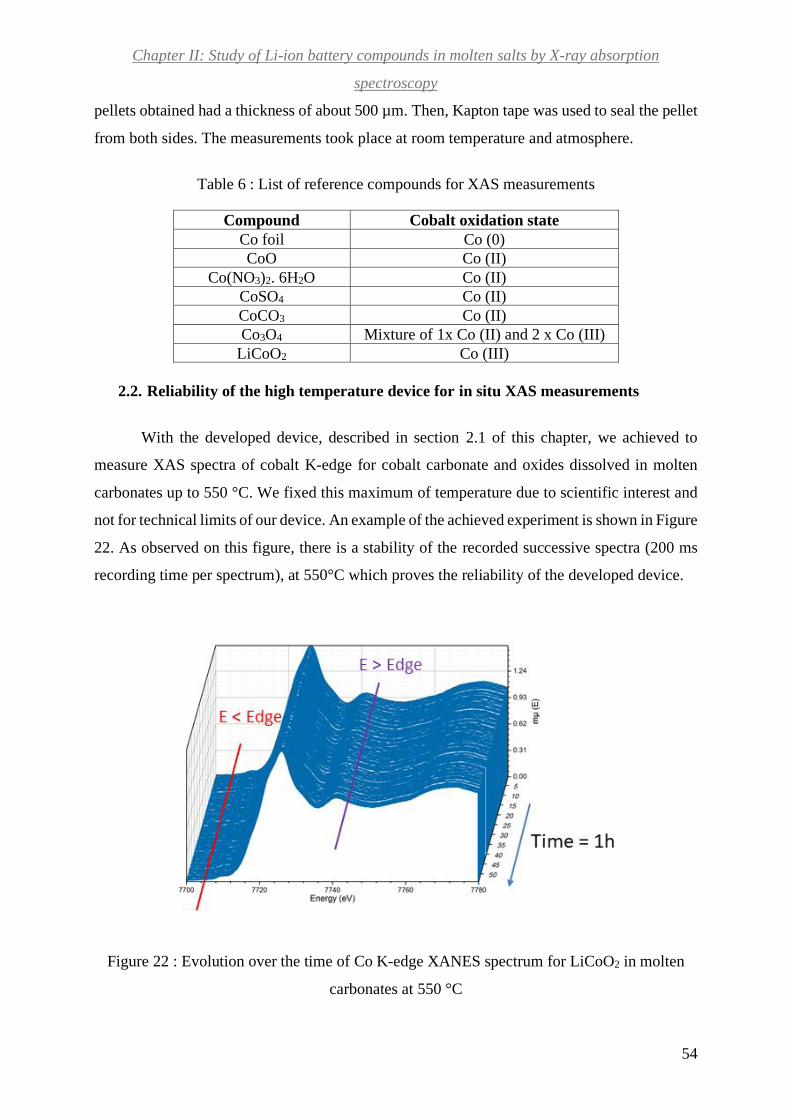
Chapter II: Study of Li-ion battery compounds in molten salts by X-ray absorption
spectroscopy
54
pellets obtained had a thickness of about 500 µm. Then, Kapton tape was used to seal the pellet
from both sides. The measurements took place at room temperature and atmosphere.
Table 6 : List of reference compounds for XAS measurements
Compound Cobalt oxidation state
Co foil Co (0)
CoO Co (II)
Co(NO3)2. 6H2O Co (II)
CoSO4 Co (II)
CoCO3 Co (II)
Co3O4 Mixture of 1x Co (II) and 2 x Co (III)
LiCoO2 Co (III)
2.2. Reliability of the high temperature device for in situ XAS measurements
With the developed device, described in section 2.1 of this chapter, we achieved to
measure XAS spectra of cobalt K-edge for cobalt carbonate and oxides dissolved in molten
carbonates up to 550 °C. We fixed this maximum of temperature due to scientific interest and
not for technical limits of our device. An example of the achieved experiment is shown in Figure
22. As observed on this figure, there is a stability of the recorded successive spectra (200 ms
recording time per spectrum), at 550°C which proves the reliability of the developed device.
Figure 22 : Evolution over the time of Co K-edge XANES spectrum for LiCoO2 in molten
carbonates at 550 °C
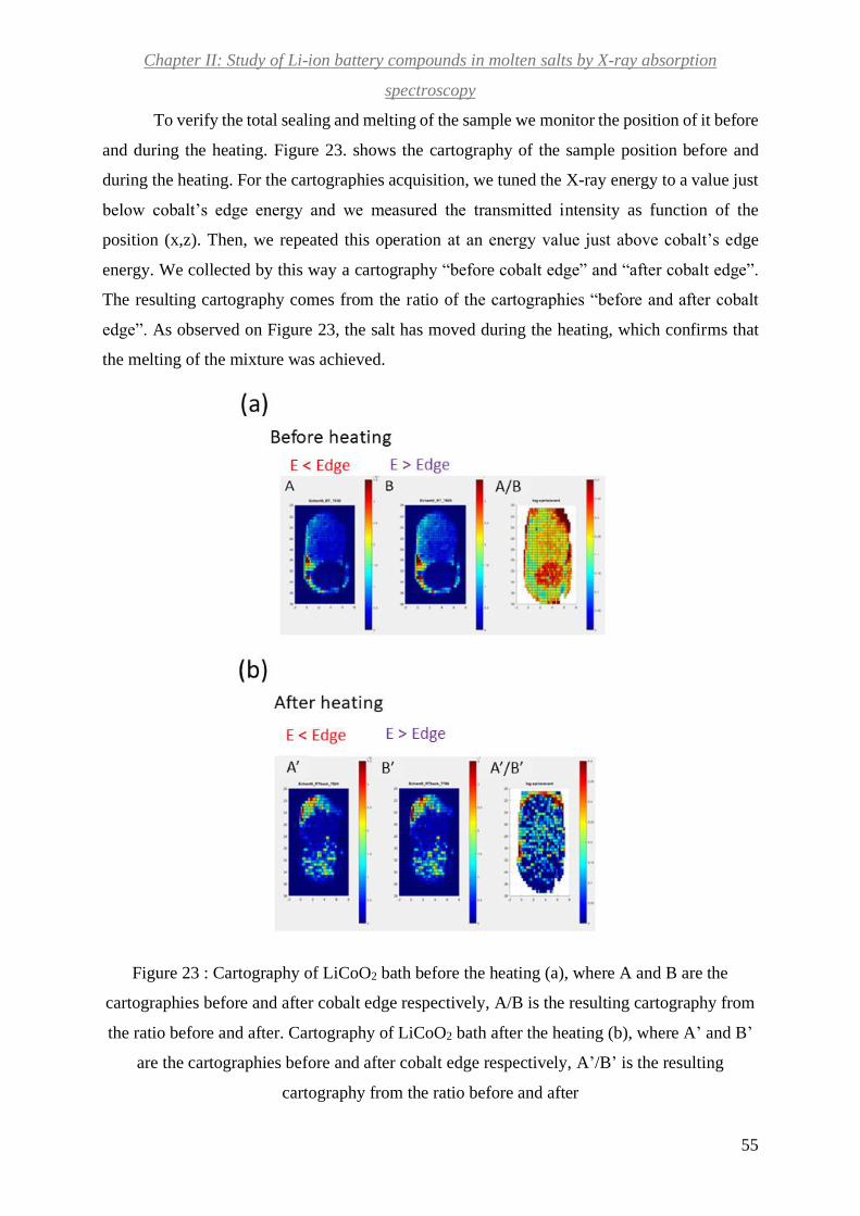
Chapter II: Study of Li-ion battery compounds in molten salts by X-ray absorption
spectroscopy
55
To verify the total sealing and melting of the sample we monitor the position of it before
and during the heating. Figure 23. shows the cartography of the sample position before and
during the heating. For the cartographies acquisition, we tuned the X-ray energy to a value just
below cobalt’s edge energy and we measured the transmitted intensity as function of the
position (x,z). Then, we repeated this operation at an energy value just above cobalt’s edge
energy. We collected by this way a cartography “before cobalt edge” and “after cobalt edge”.
The resulting cartography comes from the ratio of the cartographies “before and after cobalt
edge”. As observed on Figure 23, the salt has moved during the heating, which confirms that
the melting of the mixture was achieved.
Figure 23 : Cartography of LiCoO2 bath before the heating (a), where A and B are the
cartographies before and after cobalt edge respectively, A/B is the resulting cartography from
the ratio before and after. Cartography of LiCoO2 bath after the heating (b), where A’ and B’
are the cartographies before and after cobalt edge respectively, A’/B’ is the resulting
cartography from the ratio before and after

Chapter II: Study of Li-ion battery compounds in molten salts by X-ray absorption
spectroscopy
56
2.3. In-situ measurement of LiCoO2 (LCO) in molten Li2CO3-Na2CO3-K2CO3
eutectic
Determining cobalt average oxidation state
In situ measurements of the molten baths containing cathode materials LCO, NCA,
NMC and different reference compounds CoCO3 and Co3O4 studied in chapter III, have been
carried out on April 2019. For a matter a time, only LCO study will be presented in this section.
Figure 24 shows (a and b) in situ Co K-edge XANES before, during and after the heating for
LiCoO2, and after for NCA and NMC. At the bottom of Figure 24 (c) the Co K-edge XANES
of the references compounds is shown.
To determine the oxidation state, we follow the method proposed by Capehart and al112.
In a first step, the integral of the normalized absorption spectra Aref is measured for an arbitrary
range in the absorption edge zone as depicted in the Figure 25 for a reference compound. In our
case the reference was Co foil and the energy range was from 7690 to 7715 eV. In a second
step, the upper energy limit (EC) is determined, to calculate the integral for a series of well-
defined compounds, i.e. with known oxidation state, in a way that the value of the integral is
the same as for the reference. In a third step, the values of the edge energy shift are calculated
and plotted as a function of the oxidation state.
𝛿𝐸 = 𝐸𝐶 − 𝐸𝑅 (Eq. 26)
Where EC is the edge energy of the compound in eV and ER is the edge energy of the
reference point in eV.
A linear regression is performed in order to obtain a calibration line. In a final step, the
EC is similarly determined for the compound with unknown oxidation state and reported on the
calibration line to obtain the oxidation state.

Chapter II: Study of Li-ion battery compounds in molten salts by X-ray absorption
spectroscopy
57
Figure 24 : In situ Co K-edge XANES of LiCoO2 bath at different temperature plateaus (a),
NCA and NMC bath at room temperature after the heating (b) and 4 reference compounds (c)

Chapter II: Study of Li-ion battery compounds in molten salts by X-ray absorption
spectroscopy
58
Figure 25 : XANES Co K-edge of different reference compounds used. The purple-filled part
of the spectrum corresponds to a constant area arbitrary area (a). Calibration curve employing
different reference compounds (b).
This approach has been tested and proved to be accurate by Capehart T.W. et al.
Furthermore, it has been used by Krylova, G. et al, Huck-Iriat C. et al, in studies implying XAS
cobalt studies at K-edge 113, 114. As edge energy shift can be influenced by the oxidation state
but also by several effects concerning the beam line equipment such as calibration, this method
considers an internal reference point as unavoidable112,114. For cobalt this reference point is set
at 7709 eV114.
The determination of the average oxidation state from XANES is usually obtained by
the maximum of XANES region derivate. We used Capehart T.W. et al. approach instead of
the derivate one for several reasons. First of all, Capehart T.W. method is more robust when

Chapter II: Study of Li-ion battery compounds in molten salts by X-ray absorption
spectroscopy
59
several compound phases are present in the studied system. Furthermore, Huck-Iriat C. et al,
Krylova, G. et al, applied this approach to compounds which are similar to the ones used in this
project. They used cobalt oxides reference compounds such as: CoO, Co3O4, LiCoO2, with the
aim of analyzing Co-based catalysts for steam reforming of ethanol114 or the synthesis of
multicomponent nanocrystals113.
With this procedure the edge shift is determined for LiCoO2 in molten carbonates
sample at different temperatures, and the respective average oxidation state is determined
Figure 26. It is important to notice that before the heating in the EXAFS setup, cobalt shows an
average oxidation state of +II and not +III as expected for native LiCoO2 because the sample
are taken from bath of electrochemical experiments. This means that the reduction of Co (III)
from cathode materials into Co (II) takes place in carbonates medium. But does cobalt from
LiCoO2 bath shows the same oxidation state in solid and molten carbonates? The Figure 26
shows the evolution of the oxidation state of cobalt in the bath during the heating.
Figure 26 : Average oxidation state for LiCoO2 bath as function of temperature
LiCoO2 bath shows a slight decrease of the average oxidation state as the sample is
heated. This trend is also observed when the temperature is decreased to room temperature after
the heating. As a consequence, the oxidation state determined afterwards on the sample coming
the bath of the electrochemical experiments can be considered as a good approximation of the

Chapter II: Study of Li-ion battery compounds in molten salts by X-ray absorption
spectroscopy
60
cobalt oxidation state during these experiments. Hence, cobalt is mainly in the Co (II) form in
the molten Li2CO3-Na2CO3-K2CO3 eutectic. Table 7 shows a summary of the edge shift
obtained for calibration curve references and the studied samples.
Table 7 : Edge shift results for samples and reference compounds
Compound 𝜹𝑬 (eV) Oxidation state
Co foil 0 0
LiCoO2 6.49 3
CoO 4.17 2
CoSO4 4.57 2
Co3O4 5.09 2.5
LiCoO2 bath RT before 3.85 1.8
LiCoO2 bath RT after 2.88 1.4
LiCoO2 bath at 350 °C 3.84 1.8
LiCoO2 bath at 550 °C 2.87 1.3
NCA bath RT before 3.71 1.8
NMC bath RT before 3.86 1.9
Co3O4 bath RT before 4.62 2.2
It is observed in all the cases, that cobalt presents an average oxidation state of +II. This
confirms the reduction of cobalt Co (III) into Co (II) in molten carbonates. A slight decrease in
the oxidation state is observed for NCA, Co3O4 and NMC baths. CoCO3 bath is analyzed at
room temperature before the heating as the transmitted signal was too low to carry out the
measurement at high temperatures. This explains the absence of decrease of the oxidation state.
The surprising point is to find oxidation state lower than 2 possibly indicating the
reduction of a portion of Co (II) into metallic cobalt. We suppose that graphite from the cell,
which is in a big quantity compared to the sample, leads to a reduction process. This
phenomenon is known for iron oxides in the presence of carbon, but at much higher temperature
>1000 °C115. To verify this hypothesis supplementary studies must be carried out.
In-situ EXAFS
In a second step, we are interested in determining cobalt phases or environments at different
temperatures studied using the EXAFS part of the absorption spectra. In liquid, it is laborious
to obtain the different contributions of the absorber atom neighbors as they are constantly
moving. Simulation is generally used to face this problem109, 116. In our case, we have
surprisingly achieved to model the XAFS spectra in solid and liquid states using a linear
combination of solid reference compounds XAFS spectra at room temperature (Figure 27).

Chapter II: Study of Li-ion battery compounds in molten salts by X-ray absorption
spectroscopy
61
Figure 27 : Experimental and linear combinations of EXAFS contributions for LiCoO2 bath at
different temperature conditions: room temperature before heating (a), 350 °C (b), 550 °C (c),
room temperature after heating (d). EXAFS experimental data for reference compounds
In the case of LiCoO2 in molten carbonates, these reference compounds are the
crystalline solids previously used for the calibration curve: LiCoO2, CoO, CoCO3 and Co
metallic.Figure 27 (a), (b), (c) and (d) show the comparisons between the linear combinations
and the experimental EXAFS contributions, for LCO in Li2CO3-Na2CO3-K2CO3 eutectic at
different temperatures. Figure 27 (e) exhibits the EXAFS experimental data of references
compounds. Only two components, CoO and LiCoO2, were sufficient to model the spectra. The
fits are rather good for the RT before heating and at 350°C and it is excellent at RT after heating.
In the melt (550°C), the fit misses a part of the experimental data. The residue does not
correspond to any individual component of Co-O or Co-Co (first coordination sphere) that can
be extracted from any of the solid reference spectra. The missing component may come from
cobalt ions dissolved in the melt, which was the main expected component. The fact that it is
possible to model the XAFS spectra with solid seems to indicate that the cobalt is mostly in the

Chapter II: Study of Li-ion battery compounds in molten salts by X-ray absorption
spectroscopy
62
form of small aggregates in the bath and not dissolved ions. A slight decrease in the oxidation
state is observed for NCA, Co3O4 and NMC baths. CoCO3 bath is analyzed at room temperature
before the heating as the transmitted signal was too low to carry out the measurement at high
temperatures. This explains the absence of decrease of the oxidation state.
This result needs to be confirmed by running X-ray absorption experiment over a longer
duration, about several days that correspond to the standard duration of electrochemical
experiments described in the following chapter.
Figure 28 : Evolution of CoO and LiCoO2 proportion in LiCoO2 bath as function of heating
temperature
The evolution of the CoO and LiCoO2 proportion during the experiment is depicted in
Figure 28. The most dominant component is CoO, which decreases in a first step and then
increases until it becomes the only component left. The transformation of the LiCoO2 to CoO
raises the question of the role played by the graphite in the mechanism. After the experiment,
the cell has been opened and black deposit were observed within the salt. To check that no
reaction occurred between the salt (Li2CO3-Na2CO3-K2CO3 eutectic) and the graphite cell, X-
rays diffractograms of the sample before and after the EXAFS experiments have been recorded.
Both diffractograms superimpose indicating that no parasite reaction occurred. It must be noted

Chapter II: Study of Li-ion battery compounds in molten salts by X-ray absorption
spectroscopy
63
that the graphite cell has been prepared and closed in air atmosphere, leading to the presence of
oxygen within the cell that could induce the slight oxidation observed at 350°C; the procedure
could hence be improved by preparing the samples and the cells inside a gloves box.
The EXAFS spectrum of the sample at room temperature after experiment shows that
only CoO compound is present. This result is in quite disagreement with the XANES analysis
that indicates an average oxidation state of Co of 1.4 instead of 2 for CoO. Though the method
chosen here for the determination of oxidation state in the XANES part is sensitive to the choice
of the integral value, it is interesting in the case of mixtures of compounds like in our samples.
To sum up, in-situ EXAFS analysis shows divergences compared to the precedent one
(in-situ XANES). In-situ XANES analysis illustrates a supplementary reduction than expected
for the total system (mixture of Co (II) and metallic cobalt presence). On the other hand, EXAFS
analysis shows a mixture of Co (III) and Co(II) in the system. Nevertheless, the general trend
is similar for both results: a reduction of Co(III) of cathode material into Co(II). Further
experiments need to be done in the future to verify these results.
3. Conclusions
The development of a whole setup to measure the absorption spectrum of cobalt at the
K-edge in molten carbonate has been carried out to investigate the oxidation state and the
speciation of cobalt dissolved in these media. The setup has been proven to provide reliable
conditions to perform measurements at 550°C for several hours.
It has been possible to determine the cobalt oxidation state and the solid compound
formed in the cooled bathes of the electrochemical experiments in one hand and in another hand
to follow the cobalt behavior in situ when these bathes are put into the molten state again. The
results clearly show that the oxidation state of cobalt is reduced from +III to +II in molten
Li2CO3-Na2CO3-K2CO3 eutectic for all standard cathode materials LCO, NMC and NCA. For
LCO cathode material, it is transformed into CoO. Furthermore, in the running conditions of
synchrotron experiments, i.e. experiments that last 3-4 hours, cobalt stays mainly in CoO
aggregates at 550°C and is not dissolved in isolated ions as expected.

64
Chapter III: Study of Li-ion battery compounds in
molten carbonates medium
“J’ai appris que la voie du progrès
n’était ni rapide ni facile.”
Marie Curie

Chapter III: Study of Li-ion battery compounds in molten carbonates medium
65
1. Introduction
As mentioned in chapter one the main objective of this project is to determine the
feasibility of recycling Li-ion battery organic and inorganic compounds in molten salts. Alkali
carbonates show the capacity of decomposing organic compounds55 due to their oxoacidity
properties. This characteristic makes alkali carbonates good molten solvent candidates for this
project. This chapter is dedicated to the study the behavior of some particular Li-ion batteries
cathode materials, containing cobalt (in form CoIII): LCO, NCA, NMC in molten carbonates.
The challenge of recovering cobalt from these materials requires a deep comprehension of its
behavior in this medium as oxide and lithiated oxide. The scientific community has made efforts
in studying cobalt oxides in these systems with the aim of using it as cathode compounds in
molten carbonates fuel cells (MCFC).
Concerning cobalt oxide, a vast study has been carried out on the behavior of cobalt
oxide Co3O4 behavior in binary systems. Mendoza et al. have investigated deposited thin films
of this oxide on nickel substrates in (52 mol % Li2CO3-48 mol % Na2CO3),in a mixture of
air/CO2 70/30 (mol%) at 650 °C117,118. Their X-ray diffraction (XRD) and X-ray photoelectron
spectroscopy (XPS) results show that Co3O4 is transformed spontaneously within some minutes
in LiCoO2 which seems to diffuse in nickel substrates within some hours (less than 50h). Co3O4
dissolution in the same melt and atmosphere was later reported by Escudero et al.119, by using
Induced Couple Plasma- Atomic Emission Spectroscopy (ICP-AES) technique. This study
reported a value of 3.5 wt.ppm or 1.2 10-7 mol.cm-3 after 50h in the melt.
Several studies of lithiated cobalt oxide LiCoO2 behavior in molten carbonates have
been reported. Veldhuis et al studied this compound in molten (62 mol % Li2CO3-38 mol %
K2CO3) at 650°C with 66% CO2-33% O2 120. They proved by square wave voltammetry that
Co(II) is the single electroactive specie in the melt and LiCoO2 transformation into CoO in the
medium is presumed to be possible. Furthermore, their dissolution measurements obtained by
ICP-AES showed that cobalt dissolution in the medium ranges between 2-13 wt ppm or (6.6
10-8 to 4.3 10-7 mol.cm-3).
Ota et al. deepened the study of LiCoO2 solubility dependency on the atmosphere and
its saturation in 62 mol % Li2CO3-38 mol % K2CO3. They used an Ar-CO2-O2 mixture where
they varied the CO2 pressure with a fixed O2 one and vice versa 121. It has been proved by flame
atomic absorption spectroscopy (F-AAS) that LiCoO2 shows the best dissolution in the highest
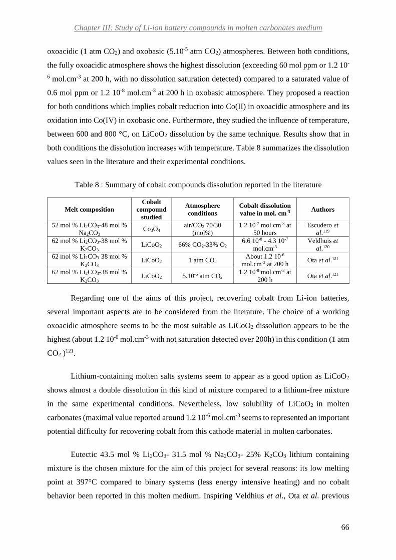
Chapter III: Study of Li-ion battery compounds in molten carbonates medium
66
oxoacidic (1 atm CO2) and oxobasic (5.10-5 atm CO2) atmospheres. Between both conditions,
the fully oxoacidic atmosphere shows the highest dissolution (exceeding 60 mol ppm or 1.2 10-
6 mol.cm-3 at 200 h, with no dissolution saturation detected) compared to a saturated value of
0.6 mol ppm or 1.2 10-8 mol.cm-3 at 200 h in oxobasic atmosphere. They proposed a reaction
for both conditions which implies cobalt reduction into Co(II) in oxoacidic atmosphere and its
oxidation into Co(IV) in oxobasic one. Furthermore, they studied the influence of temperature,
between 600 and 800 °C, on LiCoO2 dissolution by the same technique. Results show that in
both conditions the dissolution increases with temperature. Table 8 summarizes the dissolution
values seen in the literature and their experimental conditions.
Table 8 : Summary of cobalt compounds dissolution reported in the literature
Melt composition
Cobalt
compound
studied
Atmosphere
conditions
Cobalt dissolution
value in mol. cm-3 Authors
52 mol % Li2CO3-48 mol %
Na2CO3 Co3O4
air/CO2 70/30
(mol%)
1.2 10-7 mol.cm-3 at
50 hours
Escudero et
al.119
62 mol % Li2CO3-38 mol %
K2CO3 LiCoO2 66% CO2-33% O2
6.6 10-8 - 4.3 10-7
mol.cm-3
Veldhuis et
al.120
62 mol % Li2CO3-38 mol %
K2CO3 LiCoO2 1 atm CO2
About 1.2 10-6
mol.cm-3 at 200 h Ota et al.121
62 mol % Li2CO3-38 mol %
K2CO3 LiCoO2 5.10-5 atm CO2
1.2 10-8 mol.cm-3 at
200 h Ota et al.121
Regarding one of the aims of this project, recovering cobalt from Li-ion batteries,
several important aspects are to be considered from the literature. The choice of a working
oxoacidic atmosphere seems to be the most suitable as LiCoO2 dissolution appears to be the
highest (about 1.2 10-6 mol.cm-3 with not saturation detected over 200h) in this condition (1 atm
CO2 )121.
Lithium-containing molten salts systems seem to appear as a good option as LiCoO2
shows almost a double dissolution in this kind of mixture compared to a lithium-free mixture
in the same experimental conditions. Nevertheless, low solubility of LiCoO2 in molten
carbonates (maximal value reported around 1.2 10-6 mol.cm-3 seems to represented an important
potential difficulty for recovering cobalt from this cathode material in molten carbonates.
Eutectic 43.5 mol % Li2CO3- 31.5 mol % Na2CO3- 25% K2CO3 lithium containing
mixture is the chosen mixture for the aim of this project for several reasons: its low melting
point at 397°C compared to binary systems (less energy intensive heating) and no cobalt
behavior been reported in this molten medium. Inspiring Veldhius et al., Ota et al. previous

Chapter III: Study of Li-ion battery compounds in molten carbonates medium
67
works, we will report the kinetics and quantify cobalt dissolution for LCO, NCA and NMC in
this ternary system. Furthermore, we will explore the possibility of recovering cobalt from this
medium by electrolysis. Finally, preliminary studies of Li-ion battery organic compounds
(binders and separator) decomposition in molten carbonates will be discussed. The attention
will be concentrated on three Li-ion battery compounds currently used: polypropylene (PP),
carboxymethyl cellulose (CMC) and polyvinylidene fluoride (PVDF).
2. Experimental part
The first part of this section presents the set-up used for the different experiments done
in molten carbonates: furnace, heating cells, precursors used and molten salts mixing protocol.
In a second place the experimental conditions used for the electrochemical characterizations are
presented. Finally, we describe experimental conditions used for the other characterizations.
Figure 29 shows the schema of the different stages used for studying cobalt in the molten ternary
eutectic Li2CO3-Na2CO3-K2CO3.
Figure 29 : Process schema used for cobalt study in molten ternary eutectic Li2CO3-Na2CO3-
K2CO3

Chapter III: Study of Li-ion battery compounds in molten carbonates medium
68
2.1. Experimental set-up
The furnace
For all the experiences a vertical furnace was used. It heats up to the maximum
temperature of 900°C. It consists of an alumina vertical tubular center and most likely a type of
Kanthal wire wrapped around it for heating. The heating is thus achieved by the Joule effect.
The whole is contained in a steel casing. Temperature control is managed by a Eurotherm
control system which enables the melt to be kept at 450 ±1°C consistently throughout all
experiments.
Heating cell
For experiments in the eutectic binary system 56 % mol Na2CO3- 44 % K2CO3
The heating cells were composed of an inner and outer steel cell. Inside the inner one
an alumina crucible containing the salts mixture was placed. The inner steel cell was placed in
an outer and larger steel cell, which was closed at the top with a steel head. Both pieces were
sealed by a lid seal and the locking ensured by screws.
For experiments in the eutectic ternary system 43.5 % Li2CO3-31.5 % mol Na2CO3-
25% K2CO3
The heating cells were constituted of an internal Pyrex cell containing a thin layer of
glass-wool at the bottom to ensure homogenous heating. Inside of it, a glassy carbon crucible
containing the salts mixture was placed. The inner Pyrex cell was placed in an outer and larger
Pyrex cell, which was closed at the top with a Pyrex cell head. Both pieces were sealed using
silicone-free high vacuum Apiezon H grease, suitable for high temperatures. Two metallic
closing pieces joined by screws were used in order to isolate both Pyrex pieces from the room
atmosphere.
Molten salt container (crucible)
The molten salts were melted in glassy carbon crucibles from HTW SIGRADUR, in the
case of experiments carried on Li2CO3-Na2CO3-K2CO3. For the experiments done in the eutectic
system Na2CO3-K2CO3 alumina crucibles from SCERAM with a purity of 99.7% were used.

Chapter III: Study of Li-ion battery compounds in molten carbonates medium
69
Precursor compounds and molten salts used
Table 9 shows the different chemical compounds used for the experiments in molten
carbonates: cobalt precursors and alkali carbonates
Table 9 : List of chemical compounds used
Compound Form Purity Supplier
Li2CO3 Powder >99.8 % AnalaR NORMAPUR
for analysis
Na2CO3 Powder >99.8 % AnalaR NORMAPUR
for analysis
K2CO3 Powder >99.8 % AnalaR NORMAPUR
for analysis
CoCO3 Powder - Synthethised at the
laboratory
Co3O4 Powder ≥99.99%
Merck
LiCoO2 Powder 99.8% Merck
LiNi0.82Co0.15Al0.03O2 Powder - SAFT
LiNi1/3Co1/3Mn1/3O2 Powder - SAFT
All the salts and cobalt precursors were dried under vacuum at 200 °C for 72h. The
cobalt precursors were then stored in a glove box and carbonates salts in the oven at 200 °C.
Eutectic Li2CO3-Na2CO3-K2CO3 and cobalt precursor mixture preparation
The eutectic mixture is composed of 31, 5% mol Na2CO3, 43,5 % Li2CO3 and 25% mol
K2CO3. The quantity of cobalt precursor used was weighted in glove box to avoid the compound
to take moisture. Weighting carbonates was done very quickly under air and then manually
grinded with the cobalt precursor for 30 minutes. The grinded mixture was then put into a glassy
carbon crucible.
All the experiments were performed under CO2 atmosphere, a flow of 38 mL min-1.
Furthermore, 50 mL of molten salts were used and a cobalt concentration 2.5 × 10⁻⁵ mol. cm-3
for each bath. The temperature of the bath ramps up to 450°C by step of 3°C per minute. The
density of the eutectic molten Li2CO3- Na2CO3-K2CO3 system is 2.11 g cm-3 at 450°C 122. The
Figure 30 (a) shows the phase diagram of the ternary system Li2CO3- Na2CO3-K2CO3123. The
heating period was around 168h for each experiment.

Chapter III: Study of Li-ion battery compounds in molten carbonates medium
70
Figure 30 : Diagram of the ternary system Li2CO3- Na2CO3-K2CO3 with T (°C) 123 on (a).
Phase diagram of the binary system Na2CO3-K2CO3 with T (°C) on (b)124
Eutectic Na2CO3-K2CO3 preparation
The eutectic mixture is composed of 56% mol Na2CO3 and 44% mol K2CO3. Weighting
carbonates was done very quickly under air and then manually grinded for 30 minutes. The
grinded mixture was then put into an alumina crucible. The temperature of the bath ramps up
to 800°C by step of 3 °C per minute. Figure 30 (b) shows the phase diagram of the binary
system Na2CO3-K2CO3.
Preliminary studies of metallic cobalt dissolution in eutectic (56% Na2CO3-44% K2CO3)
at 800°C were carried out. A mixture of 0.1 atm CO2- 0.9 atm Ar was the initial atmosphere
conditions of all the experiments done in this molten medium with a total flow of 25 mL min-1.
Then, the atmosphere was gradually changed into a more basic one by the cutoff of CO2
followed by the addition of Na2O oxide. A 0.5 mm thick massive plate of cobalt was immersed
in the molten mixture at the beginning of the experiment. Cobalt dissolution was measured by
Inductively Coupled Plasma - Atomic Emission Spectroscopy (ICP-AES) with portions of the
melt taken over time.

Chapter III: Study of Li-ion battery compounds in molten carbonates medium
71
2.2. Electrochemical measurements
Cyclic voltammetry
Cyclic voltammetry allows a deep characterization of an electrochemical system. With
the aim of recovering cobalt by electrolysis, the comprehension of its electrochemical behavior
was explored by this technique.
For cobalt dissolution investigations in molten carbonates, cyclic voltammograms were
recorded with EG&G Princeton Applied Research potentiostat/galvanostat Model 273A. For
all the measurements, the potential was swept from the open circuit potential (OCP) towards
the cathodic one and vice versa to complete the cycle. The potential range sweep was adapted
for each precursor in order to observe the totality of cobalt electrochemical potential range.
Chronoamperometry
For exploring cobalt recovery by electrodeposition in molten carbonates,
chronoamperometry technique was used. All the measurements were carried out with EG&G
Princeton Applied Research potentiostat/ galvanostat Model 273A. The potential steps, for each
measurement, were applied from the open circuit potential (OCP) to the cathodic potential
corresponding to cobalt reduction on the working electrode.
Electrodes
A three-electrode system has been used for all the electrochemical measurements.
-The reference electrode: a pseudo-reference electrode composed of pure cobalt 4.2 mm
diameter rod welded to a steel tube. This electrode was chosen as it enables to avoid the liquid
junction potential that is present in AgI/Ag0 references. The cobalt (purity : 99.99%) was
provided by Goodfellow.
-The counter electrode: An 8 mm diameter graphite rod (Carbon Lorraine) was connected to a
1 mm diameter copper wire. Both materials have been chosen as they show good electrical
properties and they are cheap. Moreover, graphite does not pollute the melt as it does not oxidize
when current is applied.
-The working electrodes:

Chapter III: Study of Li-ion battery compounds in molten carbonates medium
72
- A 1 mm diameter silver wire 99.99 % pure from Goodfellow
- A glassy carbon plate with the dimensions: 10mm * 25.4mm, and thickness of 3mm,
from HTW SIGRADUR, which is connected to a 1 mm diameter copper wire.
The plunged length of the working electrodes was measured with a caliper at the end of
the measurements. All the electrodes were cleaned in a 1 mol HCl solution, then rinsed with
distilled water and dried. The metallic wires and rods constituting the different electrodes were
then polished with sandpaper (SiC paper # 1200, Struers), rinsed with ethanol and then dried.
The working and counter electrode wires were maintained in the molten system by an alumina
sheath with a 4mm diameter, from SCERAM.
2.3. Other characterizations
X-ray Diffraction (XRD)
This technique has been used for analyzing the deposit from electrolysis. We have used
for our measurements D8 ADVANCE powder diffractometer from BRUKER. It has a Cu target
and 1D detector Lyn Eye from BRUKER. For the measurements we used Bragg-Brentano scan
type. All the measurements were done at room temperature and atmosphere.
Thermogravimetry analysis (TGA- DSC)
Thermogravimetry analysis was used to determine the compound thermal stability of
CoCO3 reference compound. The measurements were done on a thermogravimeter SETSYS
Evolution from SETARAM. The initial mass used for the measurements was of 25,2 mg. Its
mass loss evolution was monitored from 20 to 700 °C at 5 °C/min under CO2 atmosphere.
Flame Atomic Absorption Spectroscopy (F-AAS)
Flame atomic absorption spectroscopy was used to determine the dissolved cobalt
concentration in the molten media for cobalt reference compounds and the studied Li-ion
battery cathode materials. For the F-AAS measurements a solution was prepared with: a grinded
portion of the homogenous zone of the cooled bath (after electrochemical measurements) and
a 2% mass HNO3 solution. The measurements were done on Atomic Absorption Spectrometer
PinAAcle 500 from PerkinElmer, which has a precision of 2-3%.

Chapter III: Study of Li-ion battery compounds in molten carbonates medium
73
Inductively Coupled Plasma- Atomic Emission Spectroscopy (ICP-AES)
Inductively Coupled Plasma-Atomic Emission Spectroscopy was also used to determine
the dissolved cobalt concentration in the molten media. For the ICP measurements, a solution
was prepared in the same way as for (F-AAS). The measurements were done on ICP-AES
iCAP6200 Thermofisher spectrometer, which has a precision of < 5%. The vector gas was argon
4.5 Linde (min 99.995%).
3. Results and Discussion
3.1. Metallic cobalt dissolution
Recovering cobalt from Li-ion battery cathode materials may imply the formation of
massive layers of deposit at the electrode during the electrolysis. For this reason, studying
massive metallic cobalt behavior in molten carbonates appears as important for this project.
Preliminary studies of metallic cobalt dissolution in eutectic Na2CO3-K2CO3 were carried out.
For the experimental details see section 2.1 of this chapter. The results obtained for cobalt
dissolution over time can be seen on Figure 31.
Figure 31 : Evolution of metallic cobalt (0.5 mm thick massive plate) dissolution over time
when the oxobasicity is increased in eutectic Na2CO3- K2CO3, at 800 °C
Metallic cobalt solubility increases almost linearly with the time when the oxobasicity
of the melt is increased (after 50 h of heating when the CO2 flow is cut). The same trend is

Chapter III: Study of Li-ion battery compounds in molten carbonates medium
74
observed even after the Na2O introduction. This observation leads to the conclusion that Na2O
introduction does not play a major role in metallic cobalt dissolution increase.
In Figure 31, it can be observed that cobalt dissolution increase is slow and low over the
time (after 225 h of heating in the absence of CO2 atmosphere, a dissolution of 2.10-5 mol.cm-3
is detected) and not saturation is observed after the total heating time (225h). These results
confirm previous studies carried out by P. Tomczyk et al125 ,and Yang et al 126,127 , which show
the existence of a non-zero dissolution of metallic cobalt (0.05-1 µm thick films) in molten
carbonates. Massive metallic cobalt shows a higher dissolution compared to that of thin layers
which is about 2 times higher than the one reported by Yang et al for thin layers (1.8 10-5 molar
fraction or 3.5 10-7 mol. cm-3 at 100 h of immersion)126, after the same time of immersion in the
melt. This may be explained by the difference of oxobasicity of the melt between these results
and the literature126 after 100 h of immersion. The existence of a non-negligible dissolution of
metallic cobalt could be a significant difficulty for its recovery by electrolysis.
3.2. Electrochemical behavior of cobalt in molten carbonates
In this section, three different forms of cobalt precursors were studied in molten
carbonates Na2CO3-Li2CO3-K2CO3 eutectic system. First, the study of molten carbonates
mixture without cobalt was realized in order to define the electrochemical active window. Then
CoCO3 and Co3O4 were studied as reference compounds. Finally, the behavior of three cathode
materials actually present in the Li-ion batteries market: LiCoO2 (LCO), LiNi 0.82 Co 0.15 Al 0.03
O2 (NCA) and LiNi1/3 Co 1/3 Mn1/3O2 (NMC) are presented. Table 10 summarizes the oxidation
states of the cobalt precursors studied in this chapter.
Table 10 : List of cobalt precursors studied in molten carbonates
Compound type Compound formula Compound oxidation degree
Reference CoCO3 Co (II)
Reference Co3O4 Mixture of 1x Co (II) and 2 x Co (III)
Cathode material LiCoO2 Co (III)
Cathode material Li Ni 0.82 Co 0.15 Al 0.03 O2 Co (III)
Cathode material LiNi1/3Mn1/3Co1/3O2 Co (III)

Chapter III: Study of Li-ion battery compounds in molten carbonates medium
75
3.2.1. Determination of the diffusion coefficient
For electrochemical studies, it is necessary to acquire the values of different parameters:
cobalt diffusion coefficient and the number of electrons exchanged at the electrode during the
reduction and oxidation reactions, to determine dissolved cobalt concentration in the medium.
In our case, we have approximated the diffusion coefficient value to the autodiffusion
coefficient one, as no reference compound in this medium has been found to determine the
diffusion coefficient by electrochemical means (see section 3.2.3). The cobalt autodiffusion
coefficient in the medium can be calculated by the Stokes-Einstein relation, which links the
autodiffusion coefficient of the active specie with the electrolyte viscosity by the following
equation (Eq. 27):
𝐷𝑀𝑥+ =𝑘𝐵𝑇
6𝜋𝜂𝑅 (Eq. 27)
Where:
𝐷𝑀𝑥+: the diffusion coefficient of the active specie in m2.s-1, in this case 𝐷𝐶𝑜+𝐼𝐼
kB: the Boltzmann contant 1.38 10-23 in J. K-1
T: the temperature in K
η: the viscosity in Pa.s
R: the radius of the spherical particle in m
We applied (Eq. 27) to estimate diffusion coefficient 𝐷𝐶𝑜+𝐼𝐼 in our system. From the
literature, it is known that the viscosity of the eutectic ternary Li2CO3-Na2CO3-K2CO3 at 450°C
is 36.8 mPa.s128. Furthermore, we know from XANES results in the first chapter, that cobalt
oxidation in our carbonates mixture is +II. Two limit cases appear as we think of cobalt
speciation. It might form complexes with a long lifetime or with a too short one. We consider
as hypothesis the coordination of 6 because cobalt is frequently in this coordination in
compounds containing oxygen. In the first case, the radius of the spherical particle might be
equal to R = R Co(II) + 2 RC(IV) + 2 RO-II
, where R Co(II) is the radius of ionic cobalt Co+II, RC(IV)
the radius of C+IV and RO-II the radius of O-II . The corresponding values of ionic radius
considered are equal to R Co(II) = 0.65Å129, RC(IV) = 1.4 Å129 and RO-II = 0.32 Å129. This leads to
a spherical particle radius equal to 4.09 Å. The diffusion coefficient 𝐷𝐶𝑜+𝐼𝐼 calculated with this
value corresponds to 3.5 10-7 cm2.s-1. In the second limit condition, cobalt complexes lifetime
might be too short, so that ionic cobalt is assumed to be alone in the molten medium most of
Chapter III: Study of Li-ion battery compounds in molten carbonates medium
76
the time. In this situation, the spherical particle radius corresponds to 0.65 Å 129. With this
hypothesis, cobalt diffusion coefficient 𝐷𝐶𝑜+𝐼𝐼 is equal to 2.2 10-6 cm2.s-1. In a molten salt
system, the lifetime of a complex formed between ions is of around 10-11 or 10-12 s130. For this
reason, we assumed that cobalt diffusion coefficient in our system is estimated to be of 2.2 10-
6 cm2.s-1.
3.2.2. Electrochemical stability window of eutectic molten carbonates Li2CO3-
Na2CO3-K2CO3 mixture
The voltammogram in Figure 32 shows the electrochemical window of molten
carbonates. The starting potential point was 0.6 V vs CoII/Co0. The potential sweeps from the
open circuit potential (OCP) towards the cathodic potentials and vice versa as indicated in
Figure 32. The electrochemical window is about 2.8 V and it is delimited by the oxidation and
reduction of molten carbonates according to (Eq. 28) and (Eq. 28):
At the anode:
2𝐶𝑂32− → 2𝐶𝑂2 + 𝑂2 + 4𝑒− (Eq. 28)
At the cathode:
𝐶𝑂32− + 4𝑒− → 𝐶 + 3𝑂2− (Eq. 29)
Nine other peaks are present on the voltammogram: 6 anodic peaks noted as A1, A2, A3,
A4, A5, A6 and 3 cathodic peaks: C1, C2 and C3. Towards negative potentials, we can assume
that the reduction of C-based species is observed and their further oxidation appears in peaks
A1, A2 and A3. Regarding the most oxidative potentials, (A4, A5, A6) may be the oxidation of
O-based species and their reduction are observed in peaks C2 and C3.

Chapter III: Study of Li-ion battery compounds in molten carbonates medium
77
Figure 32 : Voltammogram of eutectic Li2CO3-Na2CO3-K2CO3 on silver wire working
electrode at 450°C, 1 atm CO2
No further experiments were carried out to study the carbon and oxygen systems as the
interesting potentials for cobalt systems are in the range of [-0.5, +0.6V] vs. Co+II/Co0. In this
range, only cobalt system is observed as shown in Figure 33 (a).
3.2.3. Cobalt references compounds CoCO3 and Co3O4 in eutectic molten
carbonates Li2CO3-Na2CO3-K2CO3 mixture system
Dissolution kinetics
To evaluate cobalt recovery feasibility in our studied melt, it is important to determine
its dissolution kinetics and value. A recovery process to be considered as viable needs to fulfill
two main conditions: an important dissolution of cobalt and in a short time. We show as
example Co3O4 reference compound dissolution kinetics that has been studied by cyclic
voltammetry, as shown in the Figure 33 (a).

Chapter III: Study of Li-ion battery compounds in molten carbonates medium
78
Figure 33 : (a) Voltammogram evolution in function of time of solution containing Co3O4 in
molten eutectic ternary Li2CO3-Na2CO3-K2CO3, on silver wire working electrode at 450°C 1
atm CO2. Appearance of the cooled bath after 157h of heating (b)
The potential sweeps from the open circuit potential at 0.6 V vs. CoII/Co0 to -0.5 V vs.
CoII/Co0 and vice et versa (for details see experimental section 2.2 of this chapter). During all
the heating process the presence of only one anodic and cathodic peak is detected. Both peaks
are very close to 0 V, which confirms that cobalt redox system is observed. Figure 33 (a) shows
that for the same scan rate (100mV/s) there is an increase in the both peaks current density over
time until the saturation, which is achieved at about 157h. This result leads to the conclusion
that cobalt dissolution kinetics is slow in this molten medium. We know from the literature that
Co3O4 transforms into LiCoO2 in lithium containing salts118,117. From this transformation, we
did not expect dissolution saturation after this period of heating hours, as Ota et al. did not
detect it over 225h in the same atmosphere conditions121.
The dissolution of cobalt in the molten melt was confirmed by the physical aspect of the
bath at the end of the heating period for both reference compounds, as seen in Figure 33 (b).
The purple color of the solidified bath can be attributed to cobalt as molten carbonates mixture
alone is white.

Chapter III: Study of Li-ion battery compounds in molten carbonates medium
79
Looking for a reference compound
First, CoCO3 has been chosen as reference compound for studying cobalt behavior in
molten carbonates, as Co(II) is supposed to be more soluble than Co(III). To verify the
possibility of considering CoCO3 as a reference compound, the thermal stability of this
compound has been studied by thermogravimetric analysis as shown on Figure 34.
Figure 34 : Thermogravimetric analysis of CoCO3 between 20 to 700 °C at 5 °C/min under
CO2 atmosphere
An important endothermic peak at around 400 °C is detected in Figure 34. In order to
identify the reaction corresponding to the endothermic peak seen at 400 °C, the remaining
product has been analyzed by X-ray diffraction (XRD), seen in Figure 35. As observed, there
are two important peaks present on the XRD measurement which correspond to CoO structure.

Chapter III: Study of Li-ion battery compounds in molten carbonates medium
80
Figure 35 : X-ray diffraction measurement of CoCO3 after thermogravimetric analysis (TGA-
DSC)
The reaction that takes place is shown on (Eq. 30):
𝐶𝑜𝐶𝑂3 ⇄ 𝐶𝑜𝑂 + 𝐶𝑂2 (Eq. 30)
The mass loss percentage observed by ATG-DSC is 35%. This mass percentage is
consistent to CO2 loss with respect to (Eq. 30).
From the thermal stability study of CoCO3, it can be concluded that for all the following
electrochemical studies that are shown for CoCO3 as starting material, it is in reality CoO that
is observed in the molten medium. As a consequence, CoCO3 does not constitute a real
reference compound in molten carbonates because it decomposes below the working
temperature (450°C). Even if the CoCO3 is not stable, it is still a Co(II) species that are present.
Electrochemical characterization
Three techniques have been used for quantifying cobalt dissolution in the molten
medium: Cyclic Voltammetry (CV), Flame Atomic Absorption Spectroscopy (F-AAS) and
Inductively Coupled Plasma- Atomic Emission Spectroscopy (ICP-AES). Figure 36 shows the

Chapter III: Study of Li-ion battery compounds in molten carbonates medium
81
cyclic voltammograms of both reference compounds CoCO3 and Co3O4. One anodic and one
cathodic peak are observed in each case, whose position slightly varies depending on the
measurement’s scan rate. Table 11 shows the details concerning peaks potentials positions and
the measurement starting potential for CoCO3 and Co3O4. For the measurement details see
experimental section 2.2 of this chapter. The proximity of the reduction peaks to zero (about
100 mV shift from zero) in Figure 36 confirms the presence of dissolved cobalt in the medium.
Nevertheless, as a cobalt pseudo-reference has been used for the electrochemical
measurements, it was expected that cathodic peak would appear at 0 V. This difference can be
explained by the presence of an overpotential.
Figure 36 : Voltammograms of the solution containing Co3O4 and CoCO3 in molten eutectic
ternary Li2CO3-Na2CO3-K2CO3, on silver wire working electrode at 450°C (168h), 1 atm CO2

Chapter III: Study of Li-ion battery compounds in molten carbonates medium
82
Table 11 : Anodic peak, cathodic peak and starting measurement potentials of
voltammograms containing Co3O4 and CoCO3 in eutectic molten Li2CO3-Na2CO3-K2CO3
Compound Anodic peak position
(V vs. CoII/Co0)
Cathodic peak position
(V vs. CoII/Co0)
Measurement
starting potential
(V vs. CoII/Co0)
CoCO3 0.004±0.002 -0.138 ±0.015 0.300
Co3O4 0.102 ± 0.008 -0.109± 0.013 0.650
The presence of only one anodic and cathodic peak leads to the hypothesis that the
dissolution of cobalt occurs only under the form of Co+II. This statement was confirmed by
XANES results, shown in chapter II, which proves that the dissolved cobalt in the molten
medium has an oxidation state of +II. We know from the literature that Co3O4 transformed into
LiCoO2 in lithium-containing molten systems 117,118. Furthermore, Veldhius et al. proved that
Co+II was the only electroactive species in LiCoO2120. As a consequence, cobalt average
oxidation state +II, determined by XAS measurements in the previous chapter, is in agreement
with Veldhius et al. work. As conclusion, Co (III) is reduced into Co (II) in molten carbonates.
The voltammogram peaks morphology indicates the presence of a metal
electrodeposition phenomenon. From these results, it can be concluded that the redox reactions
taking place at the working electrode are given by the following equations (Eq. 31) and (Eq.
32):
The reduction reaction:
𝐶𝑜2+ + 2𝑒− → 𝐶𝑜 (Eq. 31)
The oxidation reaction :
𝐶𝑜 → 𝐶𝑜2+ + 2𝑒− (Eq. 32)
In the case of a metal electrodeposition phenomenon, cyclic voltammogram anodic and
cathodic peaks are linked to the concentration of the active species in the medium by Berzins
and Delahay equation (Eq. 33)131, 132,133:
𝐼𝑝𝑒𝑎𝑘 = 0.61 𝑛32𝑆𝐹(
𝑣𝐷𝐹
𝑅𝑇)
12[𝑀𝑥+] (Eq. 33)
Where:
Ipeak: the peak current detected by cyclic voltammetry in A

Chapter III: Study of Li-ion battery compounds in molten carbonates medium
83
S: working electrode surface in cm2
n: the number of exchanged electrons
v: the potential scan rate in V.s-1
D: the diffusion coefficient of the active specie in cm2.s-1, in this case 𝐷𝐶𝑜+𝐼𝐼
F: Faraday constant 96485 in C. mol-1
T: the temperature in K
R: the ideal gas constant 8.314 in J.mol-1.K-1
[Mx+]: active specie Mx+ concentration in the bulk, in mol.cm-3, in this case [Co+II]
This equation was used to determine the dissolved cobalt concentration [Co+II]. Figure
37 shows the cathodic peak current density as function of the square root of the scan rate.
Figure 37 : Cathodic peak current density evolution in function of cyclic voltammetry scan
rate square root for CoO and Co3O4 in eutectic ternary mixture Li2CO3-Na2CO3-K2CO3, at
450 °C, 1 atm CO2

Chapter III: Study of Li-ion battery compounds in molten carbonates medium
84
The slope value obtained from Figure 37 corresponds to (0.61𝑛3
2𝐹 (𝐷
𝐶𝑜+𝐼𝐼𝐹
𝑅𝑇)
1
2[𝐶𝑜+𝐼𝐼]).
With this value, the respectively dissolved cobalt concentrations [𝐶𝑜+𝐼𝐼] were calculated and
compared with Flame atomic absorption spectroscopy (F-AAS) and Inductively Coupled
Plasma- Atomic Emission Spectroscopy (ICP-AES) measurements, as shown in Table 12. For
the details about the preparation of solutions and measurements for both techniques see
experimental section 2.3 of this chapter.
Table 12 : Results of dissolved cobalt concentration [𝐶𝑜+𝐼𝐼] for Co3O4 and CoCO3 in eutectic
molten Li2CO3-Na2CO3-K2CO3
Compound
𝑫𝑪𝒐+𝑰𝑰
(cm2.s-1)
Slope
(A.cm-2. V-1/2.s1/2)
Measured
by CV
[𝑪𝒐+𝑰𝑰] (mol.cm-3)
Measured
by F-
AAS [𝑪𝒐+𝑰𝑰] (mol.cm-3)
Measured by
ICP-AES
[𝑪𝒐+𝑰𝑰] (mol.cm-3)
CoCO3 2.2 10-6 5.8 10-3 ± 0.2 10-3 5.9 10-6 0.98 10-6 17.9 10-6
Co3O4 2.2 10-6 8.5 10-3 ± 0.2 10-3 8.6 10-6 2.1 10-6 25.8 10-6
Concentration values obtained by electrochemistry are well in between the values
determined by flame spectroscopy and ICP-AES. It indicates that the estimated self-diffusion
coefficient by Stokes-Einstein relation is correct. It must be underlined that the effect of matrix,
in particular the presence of sodium, is a drawback for these analytical techniques. The values
of dissolved cobalt concentration for Co3O4 are higher than the value reported in literature for
Co3O4 (1.2 10-7 mol.cm-3 at 50h of cobalt exposure in the melt)119. This may be explained by
the difference of oxoacidity between the experimental test (1 atm CO2) and the literature
(air/CO2 70/30 (mol%) and the immersion time of cobalt in the molten melt (about 168h for the
experiment and 50h in literature)119.
3.2.4. Li-ion battery cathode materials in eutectic molten carbonates Li2CO3-
Na2CO3-K2CO3 mixture system
Afterwards, we analyzed battery electrode materials. Three Li-ion battery cathode
materials behavior were investigated in the molten medium: LCO, NCA and NMC. LCO
behavior in this system was the first battery cathode material to be investigated as it contains
only cobalt as transition metal. Secondly, NCA behavior was studied as it is constituted of two
transition metals: nickel and cobalt. Finally, NMC behavior in molten carbonates was explored
as it is composed of three transition metals: manganese, cobalt and nickel.
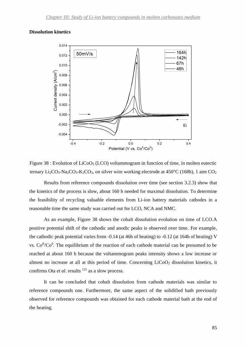
Chapter III: Study of Li-ion battery compounds in molten carbonates medium
85
Dissolution kinetics
Figure 38 : Evolution of LiCoO2 (LCO) voltammogram in function of time, in molten eutectic
ternary Li2CO3-Na2CO3-K2CO3, on silver wire working electrode at 450°C (168h), 1 atm CO2
Results from reference compounds dissolution over time (see section 3.2.3) show that
the kinetics of the process is slow, about 160 h needed for maximal dissolution. To determine
the feasibility of recycling valuable elements from Li-ion battery materials cathodes in a
reasonable time the same study was carried out for LCO, NCA and NMC.
As an example, Figure 38 shows the cobalt dissolution evolution on time of LCO.A
positive potential shift of the cathodic and anodic peaks is observed over time. For example,
the cathodic peak potential varies from -0.14 (at 46h of heating) to -0.12 (at 164h of heating) V
vs. CoII/Co0. The equilibrium of the reaction of each cathode material can be presumed to be
reached at about 160 h because the voltammogram peaks intensity shows a low increase or
almost no increase at all at this period of time. Concerning LiCoO2 dissolution kinetics, it
confirms Ota et al. results 121 as a slow process.
It can be concluded that cobalt dissolution from cathode materials was similar to
reference compounds one. Furthermore, the same aspect of the solidified bath previously
observed for reference compounds was obtained for each cathode material bath at the end of
the heating.

Chapter III: Study of Li-ion battery compounds in molten carbonates medium
86
The influence of the oxoacidity
As mention in chapter 1 in section 5.3.1.1, the level of oxoacidity in a molten carbonate
medium is defined by (Eq. 7). Different oxoacidity levels have been tested to confirm the
literature previous results which reported fully oxoacidic atmosphere (1 atm CO2) as the optimal
LiCoO2 dissolution conditions121,134. Figure 39 (a) shows voltammograms obtained for LiCoO2
in 3 oxoacidity levels: 100 % CO2 (the highest acidity), 50% CO2–50% Ar and 10% CO2-90%
Ar (the lowest oxoacidity).
Figure 39 : Voltammogram evolution of the solution containing LiCoO2 in molten eutectic
mixture Li2CO3-Na2CO3-K2CO3 on silver wire working electrode at 450°C, as function of the
oxoacidity level (a). Cathodic peak current density evolution as function of CO2 partial
pressure (b). Scan rate 100 mV/s
A shift in the cathodic peak and anodic peak toward the positive potential is observed
with the increase of oxoacidity. From the voltammograms, the cathodic peaks current density
has been analyzed as function of the medium oxoacidity (Figure 39 (b)). As observed, there is
a proportional relation between the oxoacidity (increase in pCO2 in the atmosphere) and the
cathodic peak current density increase. These results are in agreement with those of Veldhuis
et al.120l, Ota et al.121 previous studies which reported the highest dissolution in fully oxoacidic
conditions (1 atm CO2).

Chapter III: Study of Li-ion battery compounds in molten carbonates medium
87
Electrochemical characterization
Here we used the same methods used for quantifying the dissolution of the cobalt from
reference compounds. Figure 40 shows the voltammograms of each cathode material: LiCoO2
(LCO), LiNi0.82Co0.15Al0.03O2 (NCA) and LiNi1/3Co1/3Mn1/3O2 (NMC).
Figure 40 : Voltammograms of the solution containing LCO, NCA and NMC respectively in
eutectic molten Li2CO3-Na2CO3-K2CO3, on silver wire working electrode at 450°C (168h), 1
atm CO2. On the right the photos of each bath after 168h of heating
Only one anodic and one cathodic peak are observed in each case, which position
slightly varies depending on the measurement’s scan rate. We expected to observe the redox
reactions of each transition metal present on the material. In this way, we expected 2 cathodic

Chapter III: Study of Li-ion battery compounds in molten carbonates medium
88
and anodic peaks for NCA and at least 3 anodic and cathodic peaks for NMC. Table 13 shows
the details concerning peaks’ potentials positions and the measurement starting potential for
each cathode material.
Table 13 : Anodic peak, cathodic peak and starting measurement potentials of
voltammograms containing LCO, NCA and NMC in eutectic molten Li2CO3-Na2CO3-K2CO3
Compound Anodic peak position
(V vs. CoII/Co0)
Cathodic peak position
(V vs. CoII/Co0)
Measurement
starting potential
(V vs. CoII/Co0)
LCO 0.079 ± 0.005 -0.077 ± 0.008 0.600
NCA 0.143 ± 0.002 0.019 ± 0.012 0.300
NMC 0.093 ± 0.008 -0.091 ± 0.019 0.650
In the case of LCO, the observation of only one electroactive specie is in agreement with
Veldhius et al work120. This result is in coherence with XANES results in chapter II (dissolved
cobalt in the molten medium has an oxidation state of +II). The same conclusions deduced from
reference compounds voltammograms are obtained from LCO voltammogram analysis (metal
electrodeposition phenomenon present, redox reactions given by equations (Eq. 31) and (Eq.
32).
It is known from the literature, that between the couple Co(II)/Co(0) and Ni(II)/Ni(0)
there is a positive potential shift of 0.08V135 in molten carbonates. LCO and NCA
voltammograms cathodic peaks positions show a positive potential shift of about 0.07 V. This
information leads to the conclusion that the active specie observed on NCA voltammogram is
the redox reaction of nickel given by the following equations:
The reduction reaction:
𝑁𝑖2+ + 2𝑒− → 𝑁𝑖 (Eq. 34)
The oxidation reaction:
𝑁𝑖 → 𝑁𝑖2+ + 2𝑒− (Eq. 35)
To understand which active specie is observed (Co, Ni or Mn) in the case of NMC, the
standard potentials of these elements in molten carbonates are required. The reaction potentials
for manganese in molten carbonates have not been found in literature. Table 14 shows a

Chapter III: Study of Li-ion battery compounds in molten carbonates medium
89
summary of the different reaction potentials for nickel, cobalt and manganese, found in
literature, in several molten chlorides with a reference electrode Ag(I)/Ag(0)135. A negative
shift potential of about 0.8V compared to cobalt and 1 V compared to nickel is observed for
manganese in Table 14. Assuming that a similar relative potential shift is observed in molten
carbonates, we can conclude that the voltammogram does not show a reaction involving
manganese as active specie. The anodic peak of NMC is wider that LCO and NCA ones, and it
englobes their potential range. For this reason, we suppose that both redox couples Co(II)/Co(0)
and Ni(II)/Ni(0) the reaction are observed on NMC voltammogram. In this case, we cannot
define the contribution of each element on the voltammogram. Simulations of this system could
enable to determine these contributions in the future.
Table 14 : Different reaction potentials for nickel, cobalt and manganese found in literature
for several molten salts with a reference electrode Ag(I)/Ag(0)
Melt Ni(II)/Ni(0)
(V)
Co(II)/Co(0)
(V)
Mn(II)/Mn(0)
(V)
Mn(IV)/Mn(III)
(V)
LiCl-KCl -0.068 -0.264 -1.122 Beyond the melt
MgCl2-NaCl-KCl -0.112 -0.290 -1.114 Not reported
MgCl2-KCl -0.167 -0.36 -1.208 Not reported
As for reference compounds, the morphology of voltammogram peaks corresponds to
the presence of a metal electrodeposition phenomenon. Once again, Berzins and Delahay
relation (Eq. 33) was used for calculating[𝐶𝑜+𝐼𝐼] in the case of LCO, [𝑁𝑖+𝐼𝐼] in the case of
NCA and both of them for NMC. Figure 41 shows the cathodic peak current density as function
of the square root of the scan rate.
To calculate dissolved nickel concentration, the nickel diffusion coefficient value 𝐷𝑁𝑖+𝐼𝐼
was firstly calculated by using once again Stokes-Einstein relation (Eq. 27) and ternary eutectic
viscosity value from literature128 . Concerning the particle radius, we consider that, as for cobalt,
the ionic radius nickel of Ni+II is 0.69 °A129. From calculations a nickel diffusion coefficient
value DNi+𝐼𝐼 = 2.1 10-6 cm2.s-1 was obtained.

Chapter III: Study of Li-ion battery compounds in molten carbonates medium
90
Figure 41 : Cathodic peak current density evolution in function of cyclic voltammetry scan
rate square root for LCO, NCA and NMC in eutectic ternary mixture Li2CO3-Na2CO3-K2CO3,
at 450°C (168h), 1 atm CO2
Table 15 shows the results of dissolved cobalt [𝐶𝑜+𝐼𝐼] and nickel [𝑁𝑖+𝐼𝐼] concentrations
estimated by electrochemistry and compared with Flame atomic absorption spectroscopy (F-
AAS) and Inductively Coupled Plasma- Atomic Emission Spectroscopy (ICP-AES)
measurements.
The concentration values obtained by electrochemistry are in the case of LCO in
between of the values determined by flame spectroscopy and ICP-AES, as observed for the
reference compounds. In the case of NCA, the concentration values found by the three
techniques are quite similar. For NMC, the concentration estimated by electrochemistry is not
between the values determined by the other techniques. This can be explained as we do not
determine the contribution of each element (nickel and cobalt) in the cyclic voltammogram.

Chapter III: Study of Li-ion battery compounds in molten carbonates medium
91
Table 15 : Results of dissolved cobalt, nickel, aluminum and manganese concentrations for
LCO, NCA and NMC in eutectic molten Li2CO3-Na2CO3-K2CO3
Cathode material LCO NCA NMC
Slope
(A.cm-2.V-1/2.s1/2) 6.9 10-3± 0.2 10-3 6. 10-3± 0.1 10-3 5.5 10-3± 0.2 10-3
Measured by CV [𝐶𝑜+𝐼𝐼] (mol.cm-3)
7.10-6 - 5.6 10-6
Measured by
F-AAS [𝐶𝑜+𝐼𝐼] (mol.cm-3) 1.4 10-6 1.3 10-6 43.0 10-6
Measured by ICP-AES [𝐶𝑜+𝐼𝐼] (mol.cm-3)
16.5 10-6 2.7 10-6 29.6 10-6
Measured by CV [𝑁𝑖+𝐼𝐼] (mol.cm-3)
- 6.2 10-6 5.7 10-6
Measured by
F-AAS [𝑁𝑖+𝐼𝐼] (mol.cm-3) - 7. 10-6 0.5 10-6
Measured by ICP-AES [𝑁𝑖+𝐼𝐼] (mol.cm-3)
- 7.9 10-6 2 10-6
Measured by
F-AAS [𝑀𝑛+𝑥] (mol.cm-3) - - 2.12 10-6
Measured by ICP-AES [𝑀𝑛+𝑥] (mol.cm-3)
- - 5.7 10-6
Measured by F-AAS [𝐴𝑙+𝐼𝐼𝐼] (mol.cm-3)
- 2. 10-6
Measured by ICP-AES [𝐴𝑙+𝐼𝐼𝐼] (mol.cm-3)
- 1.1 10-6 -
As before, we can conclude that the estimated self-diffusion coefficient by Stokes-
Einstein relation is correct. The effect of matrix and in particular the presence of sodium is in
this case a drawback for some flame spectroscopy and ICP-AES measurements.
Ota et al. reported the maximal cobalt dissolution of LCO in molten carbonates which
exceeds 1.2 10-6 mol. cm-3 at 200 h which are quite similar to the values measured by flame
spectroscopy for LCO.
Example of electrodeposition of cobalt from cathode material LCO in molten carbonates
Several tests have been done to recover cobalt from cathode materials LCO, NCA and
NMC by electrodeposition in molten carbonates. Glassy carbon, graphite and silver have been
used as working electrode during the experiments. The choice of cathodic potential to be
applied during the electrolysis has been done, as in the example on Figure 42.

Chapter III: Study of Li-ion battery compounds in molten carbonates medium
92
Figure 42 : Selected potential for electrolysis (-0.3 V vs. CoII/Co0) in (a), photo of the
electrodeposited matter (b)
The recovered deposit was analyzed by X-Ray diffraction. Figure 43 shows as example
the X-ray diffractogram of a deposit obtained by electrolysis, on glassy carbon working
electrode. The deposit on the electrode was then analyzed by X-Ray diffraction showing only
the presence of carbonates and graphite from the counter electrode in it.
Figure 43 : XRD diagram of the electrodeposited matter

Chapter III: Study of Li-ion battery compounds in molten carbonates medium
93
3.3. Battery organic compounds in molten carbonates
As Li-ion batteries cathode materials are composite materials containing organic
matters, the study of cathode binders: polyvinylidene fluoride (PVDF) and carboxymethyl
cellulose (CMC) were studied in our team. Furthermore, separator material polypropylene (PP)
has also been investigated in molten carbonates. For more information about these Li-ion
battery constituents, see details in section 2 of chapter I. This project was principally carried
out by Arturo Melendez Ceballos (post-doc) and Gabriele Miranda (internship).
All these compounds were pyrolyzed in molten Li2CO3-Na2CO3-K2CO3. Two kinds of
compounds were present in the materials studied: heavy (Tboil>20 °C) and light compounds
(Tboil< 20°C). Figure 44 shows the set-up used for the pyrochemical reaction and the gas
recovery. Several techniques were used to identify the structure of pyrochemical reaction
products: Gas chromatography coupled to Mass Spectroscopy (GC-MS), Fourier Transform
Infrared spectroscopy (FTIR), Nuclear Magnetic Resonance (NMR) and Diffusion Ordered
Spectroscopy (DOSY). The solid products were analyzed by the following techniques:
Scanning Electron Microscopy (SEM), Transmission Electron Microscopy (TEM), X-Ray
Diffraction (XRD) and Brunauer-Emmett-Teller (BET).
Figure 44 : Experimental set-up used for the pyrochemical reaction in eutectic molten Li2CO3-
Na2CO3-K2CO3 carbonates at 450 ° C and gas recovery (from A. Meledez report)
The results show that for polypropylene (PP) pyrolysis leads to the formation of a great
variety of products of different molecular weights. Most of the compounds were aliphatic

Chapter III: Study of Li-ion battery compounds in molten carbonates medium
94
hydrocarbons (alkanes, alkenes and alkynes) ranging from 7 to 30 carbons. The other
compounds present were oxygenated compounds.
Concerning the carboxymethylcellulose (CMC) pyrolysis products, they included acetic
acid and two groups of hydrocarbon compounds: non oxygenated and oxygenated. The non-
oxygenated hydrocarbons were constituted of aliphatic carbons (saturated and unsaturated)
varying from 14 to 30 carbons. Their formula correspond to: CxHy 14 ≤ x ≤ 30 , 28 ≤ y ≤ 62.
The oxygenated hydrocarbons correspond to the following formula: CxHyOz 4≤ x ≤10, 8 ≤ y ≤
18, 1 ≤ z ≤ 2. Solid carbon has also been obtained from the pyrolysis. This carbon was tested
as anodes in Li-ion batteries showing a poor performance.
Concerning polyvinylidene fluoride (PVDF) pyrolysis, three different kinds of products
were obtained: liquid, solid and gaseous products. In fact, a yellowish liquid soluble in ethanol
and acetone has been obtained. As for CMC, solid carbon was produced from pyrolysis.
Concerning the gaseous products, mainly aromatic compounds were obtained, followed by
small and medium length hydrocarbons. No HF vaporization was detected and the presence of
LiF was detected in the molten salt.
From these preliminaries results, the global mass balance was established. It divides the
pyrolysis products into three main fractions: solid residues, heavy organic compounds (olefins
and paraffins) and volatile organic compounds. Figure 45 shows an example of the results
obtained from this study.
Figure 45 : Condensed product from CMC pyrolysis (a). MEB (b) and XRD (c) analysis of
the solid product obtained after salt removal from CMC pyrolysis
The reuse of products proceeding from polymers pyrolysis can be a potential alternative
to valorize them (which are burned at a large-scale process). Furthermore, giving Li-ion

Chapter III: Study of Li-ion battery compounds in molten carbonates medium
95
batteries organic compounds a second life will contribute to the reduction of environmental
impacts issues from Li-ion battery recycling (gas emissions) and may be the cost of some
process steps (gas treatment before the emission).
Regarding Li-ion batteries recycling, the valuable elements of industrial interest to be
recovered are essentially metals. For this reason, we studied the influence of this kind of organic
compounds on cobalt dissolution. Figure 46 shows the comparison cobalt dissolution with and
without the addition of polymer CMC. For both cases, the voltammogram shows the presence
of an anodic and a cathodic peak. Their positions and current density can be seen in Table 16.
For both measurements the starting point was corresponds to the OCP of each system.
Figure 46 : Voltammograms of the solution containing LCO in eutectic molten Li2CO3-
Na2CO3-K2CO3 in presence and without CMC polymer addition. Measurements on silver wire
working electrode at 450°C (168h), 1 atm CO2.

Chapter III: Study of Li-ion battery compounds in molten carbonates medium
96
Table 16 : Anodic peak, cathodic peak and starting measurement potentials of
voltammograms containing LCO in eutectic molten Li2CO3-Na2CO3-K2CO3 with and without
CMC polymer addition
Compound
Anodic peak
position
(V vs. CoII/Co0)
Cathodic peak
position
(V vs. CoII/Co0)
Cathodic peak
current density
(A.cm-2)
Measurement
starting
potential
(V vs. CoII/Co0)
LCO with CMC
addition 0.02 -0.11 1.67 10-3 0.2
LCO without CMC
addition 0.07 -0.12 3.67 10-3 0.4
As the current density of both cathodic peaks is compared, LCO peak without CMC
shows a current density about 2 times higher than when adding it. As peaks current density is
linked to dissolved cobalt concentration (Eq. 33), it can be concluded CMC polymer presence
decreases the solubility of cobalt from LCO in eutectic Li2CO3-Na2CO3-K2CO3.
4. Conclusions
Li-ion battery organic and cathode materials recycling feasibility was investigated in
molten carbonates. Metallic cobalt dissolution was studied in molten carbonates.
Electrochemical characterizations were carried out for different cathode materials in molten
carbonates to quantify the dissolution process of the active species (cobalt or nickel) in the
molten medium. Furthermore, electrochemical techniques allowed analyzing of the dissolution
kinetics.
It was shown from cyclic voltammetry measurements that cobalt from CoCO3, Co3O4,
LCO, NCA and NMC cathode materials is dissolved in molten carbonates. Nevertheless, cobalt
shows both a low and slow dissolution in that molten systems. The dissolved cobalt in the
molten melt appears to be insufficient for recovering it by electrodeposition, as proved after
analyzing the recovered matter after electrolysis. Regarding the conclusion withdrawn about
the active species detected by cyclic voltammetry for NCA and NMC, test with metallic
electrodes of nickel and manganese could be done to confirm the redox couple observed.
In what concerns Li-ion battery organic compounds, molten carbonates seem to be a
good alternative to explore in the future. It was shown that the pyrolysis of all the studied

Chapter III: Study of Li-ion battery compounds in molten carbonates medium
97
separators and binders leads to the production of hydrocarbons. The volatile compounds
produced during the reaction were not recovered and are still to be characterized. Furthermore,
in the case of PVDF binder, no HF vaporization was detected but the presence of LiF was
detected in the molten salt.

98
Chapter IV: Study of Li-ion battery compounds in
molten chlorides medium
“ Nous devons croire que nous
sommes doués pour quelque
chose, et que cette chose, à
n'importe quel prix, doit être
atteinte. ”
Marie Curie

Chapter IV: Study of Li-ion battery compounds in molten chlorides medium
99
1. Introduction
It has been shown in the precedent chapter that exploring Li-ion battery organic
compounds in molten carbonates seems to be an interesting approach. Nevertheless, cobalt from
cathode materials shows a low and slow dissolution in this medium. Molten chlorides medium
may be an alternative for recovering this valuable metal from cathode materials. This chapter
is dedicated to the behavior of cobalt from Li-ion battery cathode materials and its recovery in
molten chlorides medium. It has been shown that molten chlorides are able to solubilize metallic
cations of oxides such as Ti97, Ta98, Nb98, Ce99 and recovering them by electrolysis. Could this
capacity of chlorides be applied for lithiated cobalt oxides?
In the previous chapter, it has been suggested that a “good” molten medium for cobalt
recycling should exhibit two key features. On the one hand, it has to solubilize the oxides and
cations found in Li-ion batteries; on the other hand, it should keep unchanged metallic cobalt
that could be deposited onto the electrode. The literature provides information concerning the
two key features needed for an efficient cobalt recovery. Indeed, few studies have been devoted
to quantify cobalt dissolution and electrodeposition in alkali-containing chlorides, especially in
eutectic LiCl-KCl and NaCl-KCl.
Few studies have been carried out on metallic cobalt and its oxides in alkali chlorides.
Metallic cobalt has been reported as not reacting with the eutectic LiCl-KCl and NaCl-KCl
melts135 ( melting points 355 °C and 657°C respectively54,94,95). This is an advantage face to
metallic cobalt behavior in molten carbonates, where it does not remain totally stable. However,
no value of its dissolution has been reported. Concerning cobalt oxides dissolution, it has not
been widely studied in molten chlorides. Delarue started by studying the stability of a mixture
of Co3O4 and Co2O3 in eutectic LiCl-KCl136. From this investigation, it was suggested that
Co3O4 is transformed into Co2O3 in the melt and that both oxides are only partially soluble.
Nevertheless, this study is essentially empiric. Concerning cobalt oxides dissolution, only one
value has been reported in alkali chlorides mixtures. A solubility value of Co3O4 solubility has
only been reported in 50% mol NaCl-50%KCl by Ishitsuka et al. This work was carried out at
727 °C in three different acidity conditions: 100%O2 coupled with 10-2 molar fraction of Na2O2
introduction, 10% O2-N2, and 1% HCl-N2 atmosphere. Ishitsuka et al. showed that Co3O4
highest solubility correspond to the most acidic condition, with a corresponding value of 750
ppm.

Chapter IV: Study of Li-ion battery compounds in molten chlorides medium
100
Cobalt electrodeposition has been carried out in LiCl-KCl confirming not only the
recovery of metallic cobalt by electrolysis in molten chlorides, but also providing valuable
pieces of information about the mechanism taking place during electrolysis. Cobalt
electrodeposition was accomplished by Behl through linear sweep voltammetry technique. It
was proven that cobalt ions Co(II) reduction is reversible and results in the deposition of solid
metal at the electrode surface (glassy carbon working electrode)137. Later studies of the
electroreduction of cations Co+II carried on by Lantelme et al. by chronopotentiometry, provide
similar results138. Delarue G. also investigated Co+II cations by electrochemical means (curves
potential-intensity). This technique proved that in this molten medium, Co+II cation is reduced
into Co (0) and Co+III is too oxidant to exist (instead, chlorides reduction takes place). Co+II
reduction mechanism has been notably studied by Lantelme et al., by cyclic voltammetry and
chronopotentiometry139. The corresponding results show that cobalt ions reduction occurs in a
single two-electron step, confirming Delarue previous qualitative result regarding the number
of electrons exchanged during reduction136.
In general, alkali molten chlorides seem to be a more promising alternative than molten
carbonates as metallic cobalt is not soluble in them. Eutectic LiCl-KCl appears to be a more
suitable choice than 50% NaCl- 50%KCl for several reasons. First of all, it has a lower melting
point (355°C compared to 657°C). Furthermore, a low solubility of cobalt oxide has been
quantified in NaCl-KCl while in LiCl-KCl there is only an empiric study. As a consequence,
the experiments shown in this chapter are all done in LiCl-KCl eutectic. Concerning the
atmosphere, we have chosen to work in an inert atmosphere for two reasons. The solubility
studies carried out in NaCl-KCl, mentioned before, showed that the lowest solubility is obtained
in basic atmosphere (oxygen atmosphere). We do not choose an acidic atmosphere (ex: HCl)
even if it was reported to lead to best solubility for security issues.
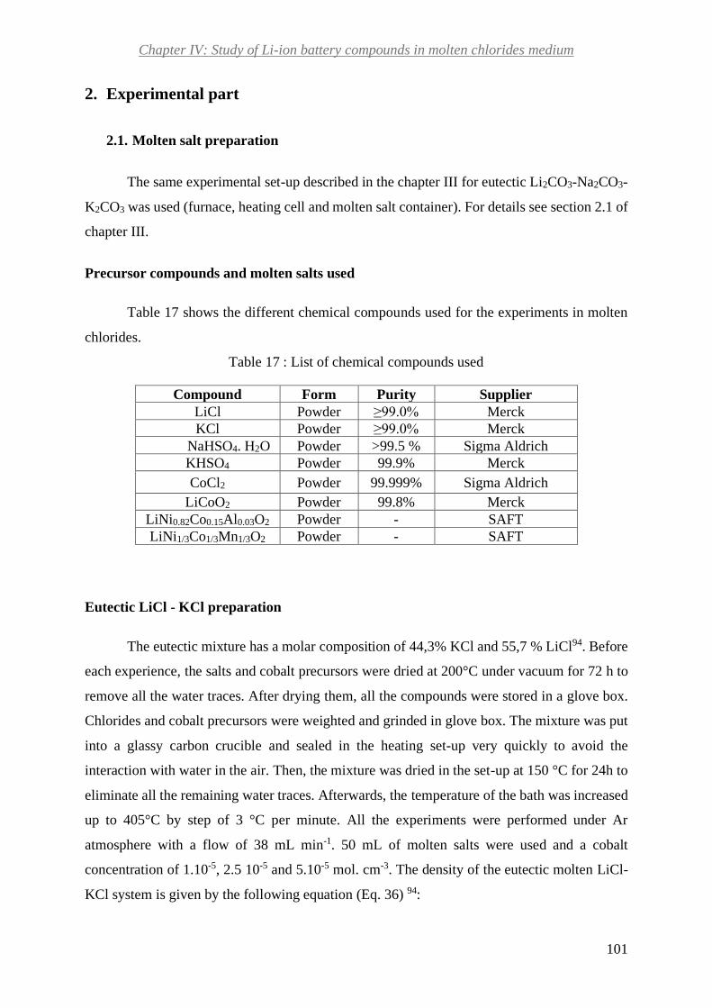
Chapter IV: Study of Li-ion battery compounds in molten chlorides medium
101
2. Experimental part
2.1. Molten salt preparation
The same experimental set-up described in the chapter III for eutectic Li2CO3-Na2CO3-
K2CO3 was used (furnace, heating cell and molten salt container). For details see section 2.1 of
chapter III.
Precursor compounds and molten salts used
Table 17 shows the different chemical compounds used for the experiments in molten
chlorides.
Table 17 : List of chemical compounds used
Compound Form Purity Supplier
LiCl Powder ≥99.0% Merck
KCl Powder ≥99.0% Merck
NaHSO4. H2O Powder >99.5 % Sigma Aldrich
KHSO4 Powder 99.9% Merck
CoCl2 Powder 99.999% Sigma Aldrich
LiCoO2 Powder 99.8% Merck
LiNi0.82Co0.15Al0.03O2 Powder - SAFT
LiNi1/3Co1/3Mn1/3O2 Powder - SAFT
Eutectic LiCl - KCl preparation
The eutectic mixture has a molar composition of 44,3% KCl and 55,7 % LiCl94. Before
each experience, the salts and cobalt precursors were dried at 200°C under vacuum for 72 h to
remove all the water traces. After drying them, all the compounds were stored in a glove box.
Chlorides and cobalt precursors were weighted and grinded in glove box. The mixture was put
into a glassy carbon crucible and sealed in the heating set-up very quickly to avoid the
interaction with water in the air. Then, the mixture was dried in the set-up at 150 °C for 24h to
eliminate all the remaining water traces. Afterwards, the temperature of the bath was increased
up to 405°C by step of 3 °C per minute. All the experiments were performed under Ar
atmosphere with a flow of 38 mL min-1. 50 mL of molten salts were used and a cobalt
concentration of 1.10-5, 2.5 10-5 and 5.10-5 mol. cm-3. The density of the eutectic molten LiCl-
KCl system is given by the following equation (Eq. 36) 94:

Chapter IV: Study of Li-ion battery compounds in molten chlorides medium
102
𝜌(𝑇) = 2.0286 − (5.2676 10−4)𝑇 (Eq. 36)
Where: T is the temperature in K. At the working temperature of 405°C, 𝜌= 1.67 g cm-
3 94. The heating period was of about 3 days for each experience.
2.2. Electrochemical measurements
The same electrochemical techniques and protocol used in chapter III are here applied.
Regarding cyclic voltammetry the same theoretical approaches are used in this chapter while in
the case of chronoamperometry, theoretical approaches have been applied for determining
cobalt diffusion coefficient value.
Chronoamperometry
Chronoamperometry has been used for recovering cobalt by electrolysis and
determining its diffusion coefficient. Gold, graphite and cobalt were used as working, counter
and reference electrodes respectively, for the experiments to determine cobalt diffusion
coefficient. For electrolysis, cobalt and Ag I/Ag were used as reference electrodes and the same
working and counter ones. For the experiments to determine the diffusion coefficient, the
potential steps from 0.30 V to -0.25 vs. CoII/Co0. For the first electrolysis shown in this chapter,
the potential steps from -0.10 V to -0.65 V vs. AgI/Ag0., and for the second one from 0.50 V to
-0.30 vs. CoII/Co0.
Electrodes
A three-electrode system has been used for all the electrochemical measurements.
- The reference electrodes:
- The same pseudo-reference of cobalt used in Chapter III
- A silver electrode named AgI/Ag0 that consists in an alumina tube closed by sintered
4 mm diameter alumina plug, from Radiometer analytical. Inside of the tube a 1 mm
diameter silver wire was plunged in a mixture of eutectic LiCl-KCl and Ag2SO4. The
optimal portion of 5% mol of Ag2SO4/ LiCl-KCl was decided by considering the
literature140.
- The working electrodes:

Chapter IV: Study of Li-ion battery compounds in molten chlorides medium
103
- A 1 mm diameter cobalt wire 99.99 % pure from Goodfellow
- A 1 cm2 gold plate 99% pure from Goodfellow
- A 1mm diameter gold wire 99% pure from Goodfellow
-A 1 mm diameter tungsten wire
- A 4.5 mm diameter glassy carbon rod (HTW SIGRADUR)
- The same counter electrode described in Chapter III was used
The immersed length of the working electrodes was measured with a caliper at the end
of the measurements. Then, all the electrodes were cleaned with distilled water and dried.
Finally, all the metallic pieces composing the electrodes were polished with sandpaper (SiC
paper #1200, from Struers), rinsed with ethanol and dried. The working and counter electrode
wires were maintained in the molten system by the same alumina sheath used for electrodes in
chapter III.
2.3. Other characterizations
Inductively Coupled Plasma- Atomic Emission Spectroscopy (ICP-AES) and
Flame atomic absorption spectroscopy (F-AAS) were used with the same aim described in
chapter III. The same equipment and protocol were also used. X-ray Diffraction (XRD) was
used for analyzing the product of the thermal pretreatment of cathode materials with
hydrogenosulfates and the deposit from electrolysis in molten chlorides. The deposit was rinsed
with distilled water and dried before the XRD measurements. The same measurements
conditions and equipment described in chapter III have been used. Energy-dispersive X-ray
spectroscopy (EDX) was used to determine the composition of the deposit. The deposit was
taken off from the working electrode at the end of the electrolysis with a spatula, rinsed with
distilled water and dried before being analyzed. The equipment used was a Field effect gun
Scanning Electron Microscope from HITACHI-SU-70. It has a detector X-Max from Oxford
Instruments, with a surface of 50 mm2. The measurements were done at room temperature and
atmosphere. A conductor support of carbon was used for all the EDX measurements.

Chapter IV: Study of Li-ion battery compounds in molten chlorides medium
104
3. Results and discussion
In this chapter, the study of different cobalt compounds behavior in eutectic LiCl-KCl
molten system is presented. First, the study of this melt without cobalt was done to define the
electrochemical active window. Then CoCl2 was studied as the reference compound. Finally,
the behavior of cathode material LiCoO2 (LCO) is presented and the optimization of cobalt
solubility in this molten medium by using an additive is presented.
3.1. Electrochemical stability window of molten LiCl-KCl eutectic
Eutectic LiCl-KCl was studied by cyclic voltammetry in order to identify the
electrochemical window of this solvent (see Figure 47). The measurement started from the
anodic potential to the cathodic one and vice versa to complete the cycle. The electrochemical
window is of about 3 V, which is slightly lower than the one reported in literature135.
In Figure 47, the anodic limit is given by the oxidation of the gold working electrode
according to the following reaction (Eq. 37)135:
𝐴𝑢 ⇄ 𝐴𝑢+ + 1𝑒− (Eq. 37)
And the cathodic limit is given by the reduction of lithium cations from the molten
solvent according to(Eq. 38)135:
𝐿𝑖+ + 1𝑒− ⇄ 𝐿𝑖 (Eq. 38)
Six other peaks are present in curve (a): 4 anodic (A1, A2, A3 and A4) and 2 cathodic
ones (C1, C2). The peak A1 implies the oxidation of metallic lithium formed in (Eq. 38) and the
peak C1 implies the Au+ reduction after its oxidation by (Eq. 37).
A2, A3, A4 and C2 can be attributed to the formation of alloys gold-lithium and gold-
potassium141. Several gold-potassium alloys have been reported in literature: Au2K, Au4K,
AuK, AuKx with x= 1.28; 1.24; 1.17; 1.03; 0.54 and 0.52141. On the contrary lithium-gold alloys
are not well known in literature141.

Chapter IV: Study of Li-ion battery compounds in molten chlorides medium
105
Figure 47 : Electrochemical window of eutectic LiCl-KCl on gold wire working electrode at
405°C, 1 atm Ar. Graphite and AgI/Ag0 have been used as counter and reference electrodes,
respectively
3.2. Electrochemical study of CoCl2 precursor in molten LiCl-KCl eutectic
Testing working electrodes
Several electrochemical configurations have been tested to identify the most suitable
set-up for the electrochemical study of cobalt in this molten medium. In this way, gold, tungsten
and cobalt were used as working electrodes. Figure 48 shows the voltammograms obtained for
the three working electrodes.
The reactions observed correspond to the couple Co(II)/Co(0)136,139.The voltammogram
on cobalt electrode has only one cathodic peak which appears at -0.003V vs. CoII/Co0. The
absence of anodic peak for this voltammogram may be explained by the dissolution of metallic
cobalt from the working electrode after the oxidation of the deposited one. It was expected to
observe the transition between the end of oxidation of the electrodeposited cobalt and the
beginning of the electrode material oxidation, as it has already been observed in previous

Chapter IV: Study of Li-ion battery compounds in molten chlorides medium
106
studies for silver oxidation on a silver electrode142. This transition appears as a change on the
slope during the anodic current density increase. From this statement, it would be delicated to
study of electrochemical behavior of cobalt on a cobalt working electrode. Nevertheless, it is
possible to electrodeposit cobalt over this substrate.
Figure 48 : Voltammograms of the solution containing CoCl2 in eutectic molten LiCl-KCl, on
tungsten (black curve), gold (red line) and cobalt (blue line) working electrodes, 1 atm Ar.
Graphite and cobalt were counter and reference electrodes, respectively
Voltammograms on gold and tungsten working electrode has one cathodic and one
anodic peak, with a position that varies slightly from one electrode to another. A small shift of
cathodic peaks position towards the negative potentials (of about 0.011 V) is observed for both
working electrodes. This may be explained by the important nucleation energy needed when
depositing cobalt on a different material from itself138. The morphology of the voltammogram
peaks is characteristic of an insoluble metal electrodeposition phenomenon, which confirms
previous results of Behl works (on glassy carbon working electrode)137.

Chapter IV: Study of Li-ion battery compounds in molten chlorides medium
107
Determining cobalt diffusion coefficient
To determine the concentration of dissolved cobalt in the molten medium it is necessary
to know cobalt diffusion coefficient 𝐷𝐶𝑜+𝐼𝐼. Chronoamperometry technique was used to
quantify it. In the molten system, it can be considered that the migration phenomenon is
negligible due to the presence of the chlorides that act as supporting electrolyte. By this way
when a large and negative potential is applied to the electrode, the current at it is limited by the
diffusion rate of the active species in the medium143. This current is known as limiting diffusion
one and its expression is given by Cottrell’s equation:
𝐼𝐷 = 𝑛𝑆𝐹(𝐷
𝜋𝑡)
12[𝑀𝑥+] (Eq. 39)
Where:
ID : the chronoamperogramm limiting diffusion current in A
S: working electrode surface in cm2
n: the number of exchanged electrons
F: Faraday constant 96485 in C. mol-1
D: the diffusion coefficient of the active specie in cm2.s-1, in this case 𝐷𝐶𝑜+𝐼𝐼
t: the time in s
[Mx+]: active specie Mx+ concentration in the bulk, in mol.cm-3, in this case [Co+II]
The measurement’s period of time that respects Cottrell’s conditions depends on the
equipment. In the best of the cases it includes a time period that goes from 20 µs to 200 s131. In
fact, the current of the electrical double layer masks the limiting diffusion current at the very
small-time intervals. By contrast, it is masked at the high time intervals by the convection
current 144. The interval of time between 0.1 and 3.8 s was chosen to apply the Cottrell’s
equation. Figure 49 (a) shows the corresponding chronoamperogramm. The current density
evolution as function of 1/t1/2 for time interval chosen for applying this law is shown in Figure
49 (b).
The dissolved cobalt concentration in the medium [𝐶𝑜+𝐼𝐼] is equal to the introduced
concentration of CoCl2 (2.5 10-5 mol.cm-3). With this value, a coefficient diffusion value of
𝐷𝐶𝑜+𝐼𝐼 = 1.63 10-5 cm2.s-1 is calculated. This value is in agreement with the reported cobalt
diffusion coefficient value obtained by electrochemical means in 58.2% mol LiCl- 41.8% mol
KCl in similar temperature (400°C) 139.

Chapter IV: Study of Li-ion battery compounds in molten chlorides medium
108
Figure 49 : Chronoamperogramm for the system CoCl2 in molten eutectic ternary LiCl- KCl
at 405 °C, 1 atm Ar (a). Current density evolution as function of 1/t1/2 for Cottrell’s law
application is shown on (b). Gold, graphite and cobalt were used as working, counter and
reference electrodes. The potential step goes from 0.30 V to -0.25 vs. CoII/Co0.
3.3. Electrochemical study of LiCoO2 in molten LiCl-KCl eutectic
Here the cathode material LiCoO2 (LCO) behavior in this molten medium is presented.
As mentioned in chapter III, it has been the first cathode material to be studied because it
contains only cobalt as transition metal.
Quantifying dissolution
As in chapter III, Cyclic Voltammetry, Flame Atomic Absorption Spectroscopy (F-
AAS) and Inductively Coupled Plasma- Atomic Emission Spectroscopy (ICP-AES) were used
to quantify cobalt dissolution in the molten system. Figure 50 (a) shows the voltammogram of
the solution of eutectic LiCl-KCl containing LiCoO2. The presence of only one anodic and
cathodic peak can be observed, which position varies slightly according to the scan rate set for
the measurement. The measurement has been done from the open circuit potential (OCP)
towards the cathodic one and backwards to complete the cycle.
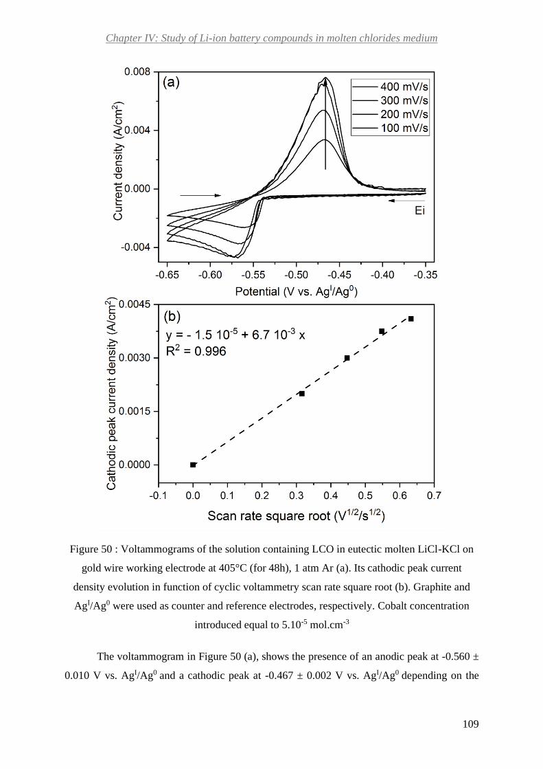
Chapter IV: Study of Li-ion battery compounds in molten chlorides medium
109
Figure 50 : Voltammograms of the solution containing LCO in eutectic molten LiCl-KCl on
gold wire working electrode at 405°C (for 48h), 1 atm Ar (a). Its cathodic peak current
density evolution in function of cyclic voltammetry scan rate square root (b). Graphite and
AgI/Ag0 were used as counter and reference electrodes, respectively. Cobalt concentration
introduced equal to 5.10-5 mol.cm-3
The voltammogram in Figure 50 (a), shows the presence of an anodic peak at -0.560 ±
0.010 V vs. AgI/Ag0 and a cathodic peak at -0.467 ± 0.002 V vs. AgI/Ag0 depending on the

Chapter IV: Study of Li-ion battery compounds in molten chlorides medium
110
measurement scan rate. In the literature, the couple Co(II)/Co(0) potential corresponds to -0.264
V vs. AgI/Ag0 135. As observed, the voltammogram peaks potential is shifted of about -0.2 V.
This difference is due to the reference electrode, where we suspected a leak. This leak was
confirmed later.
No standard potential has been reported for Co(III)/Co(II) in this medium. Furthermore,
Delarue empirical studies concluded that Co+III is too oxidant to exist in the melt136. To confirm
that the couple observed does not correspond to Co(III)/Co(II), we compared as example the
difference of standard potential of couples Co(II)/Co(0) and Co(III)/Co(II) in aqueous
solutions. In this kind of system, Co(II)/Co(0) appears at -0.28 V and Co(III)/Co(II) at 1.82 V
vs. standard hydrogen electrode. As observed, there is a difference of about 2V between both
couple potentials. Assuming that a similar difference of potential exists for both couples in our
system, Co(III)/Co(II) would appear after the anodic limit of the solvent. As a consequence, we
can conclude that the observed redox reactions correspond to the couple Co(II)/Co(0) with a
single two-electron exchange. Co+II. This implies that a small portion of Co(III) from the
cathode material is transformed into Co+II in the medium, because the voltammogram peaks’
current density is low compared to the added cobalt concentration. The maximal dissolution
has been obtained in a shorter time (48h) compared to molten carbonates (about 160h). This
leads to the conclusion that cobalt dissolution kinetics in molten chlorides is quicker than in
molten carbonates.
Berzins and Delahay relation (Eq. 33) can be used for calculating the dissolved cobalt
concentration [𝐶𝑜+𝐼𝐼] (Figure 50 (b)). A value [Co+II] = 2.6 10-6 mol.cm-3 is obtained from
calculations. This value was correlated with the results of Flame atomic absorption
spectroscopy (F-AAS) and Inductively Coupled Plasma- Atomic Emission Spectroscopy (ICP-
AES). For the preparation details see section 2.3 of this chapter. The dissolution values
determined from measurements are shown in Table 18.
Table 18 : Results of dissolved cobalt concentration [𝐶𝑜+𝐼𝐼] for LiCoO2 in eutectic molten
LiCl-KCl
Cathode
material
Slope
(A.cm-2.V-1/2.s1/2)
Measured by
CV [𝑪𝒐+𝑰𝑰] (mol.cm-3)
Measured by
F-AAS [𝑪𝒐+𝑰𝑰] (mol.cm-3)
Measured by
ICP-AES [𝑪𝒐+𝑰𝑰] (mol.cm-3)
LCO 6.7 10-3 ± 0.2 10-3 2.4 10-6 2.6 10-6 0.5 10-6

Chapter IV: Study of Li-ion battery compounds in molten chlorides medium
111
Figure 51 : Appearance of the cooled bath LiCoO2 in eutectic molten LiCl-KCl after the
heating
The concentrations values obtained by electrochemistry are well in between the values
determined by flame spectroscopy and ICP-AES. It confirms that the obtained value of cobalt
self-diffusion coefficient by chronoamperometry is correct. This difference can be attributed to
a matrix effect as for carbonates. The low solubility has been confirmed when recovering the
cooled bath shown on Figure 51. As observed in this figure, there is not blue color characteristic
of cobalt dissociation into Co+II. The melt shows a white color corresponding to molten
chlorides and LCO appears to precipitate to the bottom of it.
3.4. NaHSO4.H2O addition influence on LiCoO2 dissolution in molten LiCl-KCl
eutectic
As seen in the previous section, LCO shows a low solubility in this molten system due
to the presence of cobalt as Co (III). We have seen in chapter III, that cobalt soluble form
corresponds to Co (II) in molten carbonates. Furthermore, we know from the literature that
cobalt with the same oxidation state appears to be soluble in molten chlorides136. We look
forward finding solutions for reducing Co(III) into Co(II) previously to its dissolution in molten
chlorides.
Wang et al., proposed recently a new approach to recycle cobalt and lithium by roasting
LiCoO2 with hydrogenosulfate NaHSO4.H2O for 30 min at 600°C 145, 146.This method appears
to show a total reduction of cobalt Co(III) into Co(II) depending of the molar ratio used between

Chapter IV: Study of Li-ion battery compounds in molten chlorides medium
112
both compounds. In fact from a molar ratio 1:3 NaHSO4.H2O/LiCoO2 a total reduction of
Co(III) into Co(II) takes place145, 146.
Inspired by this approach, we used hydrogenosulfates to reduce cobalt from cathode
materials. Three cathode materials LCO, NCA and NMC were pretreated with NaHSO4.H2O
for 12h at molar proportion of 3:1 hydrogenosulfates /cathode material. Our aim here was to go
further than Wang et al. works and to determine the best protocol for the total reduction
reaction. To do it, we varied and studied the influence of different parameters on this process:
-Temperature: 188 °C, 405°C and 500°C
-Atmosphere: Ar or air
-Alkali cation: sodium (NaHSO4.H2O) or potassium (KHSO4)
Most of the experiments were carried out with NaHSO4.H2O. Figure 52 shows the
pictures of some the different thermal treatments carried out with NaHSO4.H2O as example.
As observed in Figure 52, the products obtained have a different appearance depending
on the temperature and atmosphere conditions. LCO, NCA and NMC treated at 188°C lead to
black or gray products more or less homogenous. As LCO, NCA and NMC are black powders,
we can imagine that the reaction might not be total at this temperature. Nevertheless, this
hypothesis must be verified by analytical techniques. The treatments done at 405°C seem to be
more homogenous than the ones done at 188°C, especially when air atmosphere was used (most
homogenous ones). In most of the cases there is an important difference of color compared to
the LCO, NCA and NMC powders. For LCO, the product obtained at Ar atmosphere has a dull
purple color while in air atmosphere it has a vivid purplish color. The same trend is observed
for NCA, a vivid orange product is obtained in air atmosphere while a dull greyish-orange color
in Ar atmosphere. In the case of NMC, a greyish product is obtained from the treatment in Ar
atmosphere and a pink product in air atmosphere. We analyzed the product of these thermal
treatments by XRD and XAS to determine the different products of the reaction and the cobalt
oxidation state. Moreover, we monitored the evolution (kinetics) of the reaction in-situ by XAS.

Chapter IV: Study of Li-ion battery compounds in molten chlorides medium
113
Figure 52 : Picture of the cathodes LCO, NCA and NMC cathode materials thermal
treatments with hydrogenosulfates at different temperatures (188°C, 405°C or 500°C) and
atmosphere (Ar or air) conditions
3.4.1. X-ray characterizations
Figure 53 shows the different X-ray diffractograms for each LCO pretreatment done and
at the bottom the diffractograms of both precursors used for the pretreatments.
As observed on Figure 53, there are important differences within the diffractograms as
function of the treatment temperature. In fact, there are peaks between 24° and 31° which
intensity increases from 188°C to 405°C. There are also new peaks that appears at 405°C around
50° and 55°. Atmosphere also influences on the products obtained.
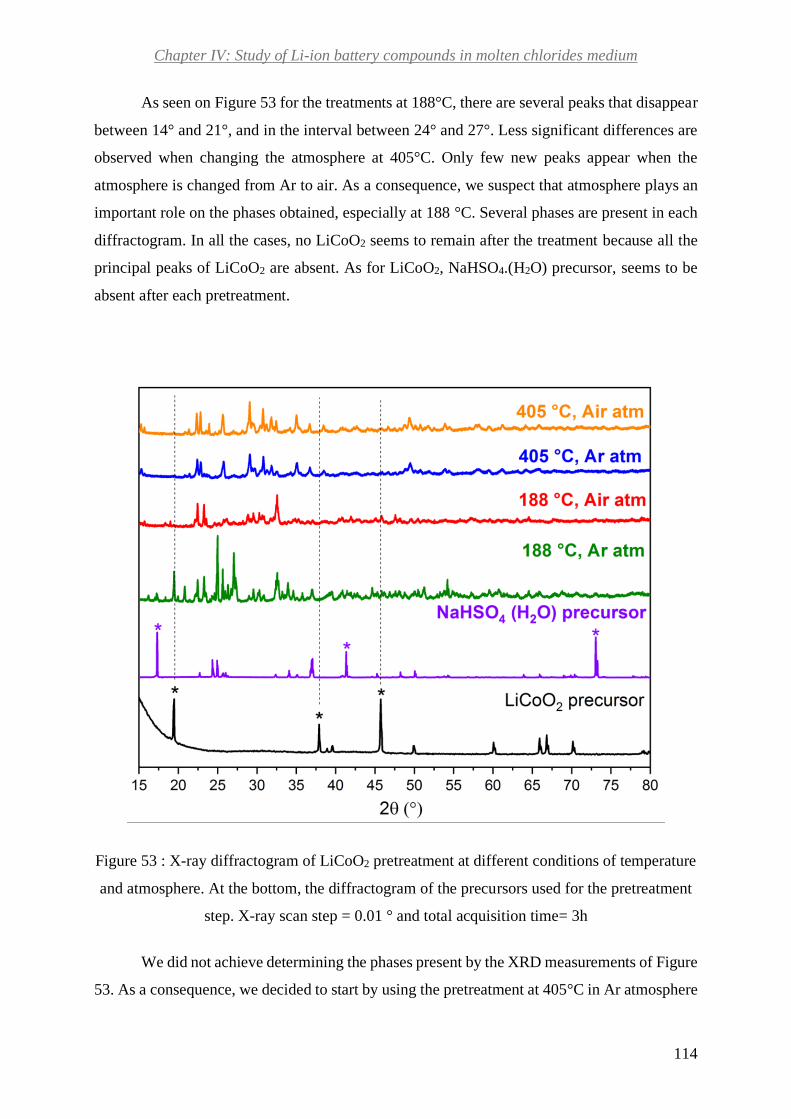
Chapter IV: Study of Li-ion battery compounds in molten chlorides medium
114
As seen on Figure 53 for the treatments at 188°C, there are several peaks that disappear
between 14° and 21°, and in the interval between 24° and 27°. Less significant differences are
observed when changing the atmosphere at 405°C. Only few new peaks appear when the
atmosphere is changed from Ar to air. As a consequence, we suspect that atmosphere plays an
important role on the phases obtained, especially at 188 °C. Several phases are present in each
diffractogram. In all the cases, no LiCoO2 seems to remain after the treatment because all the
principal peaks of LiCoO2 are absent. As for LiCoO2, NaHSO4.(H2O) precursor, seems to be
absent after each pretreatment.
Figure 53 : X-ray diffractogram of LiCoO2 pretreatment at different conditions of temperature
and atmosphere. At the bottom, the diffractogram of the precursors used for the pretreatment
step. X-ray scan step = 0.01 ° and total acquisition time= 3h
We did not achieve determining the phases present by the XRD measurements of Figure
53. As a consequence, we decided to start by using the pretreatment at 405°C in Ar atmosphere

Chapter IV: Study of Li-ion battery compounds in molten chlorides medium
115
for two reasons. First of all, the samples treated at a lower temperature seemed to be less
homogeneous and they had a gray color, similar to LiCoO2 one. The treatments carried out at
405°C and 500°C showed a purple color and they seemed to be homogenous and a total reaction
taking place. Among both atmospheres, we chose Ar one because the product seemed to be
homogenous and the XRD seemed to indicate less phases present compared to air treatment.
We carry out new XRD measurements with a better resolution over 15h. We achieved
determining most of the phases of the pretreatment product used for our electrochemical studies,
as shown in Figure 54.
Figure 54 : X-ray diffractogram of LiCoO2 treated with NaHSO4.H2O at 405 °C, in Ar
atmosphere. Scan step= 0.01° and total acquisition time= 15h
We suppose that 4 or 5 phases are present in the XRD measurement. We achieved to
determine 3 phases which are: beta-NaLi(SO4), Na2Co(SO4)2.4H2O and HNa3(SO4)2. Figure 54
confirms that the precursors are not present anymore after the treatment. We can see that three
sulfate phases are obtained. Furthermore, it confirms the reduction of cobalt from LiCoO2 after
the treatment, leading to the formation of a sulfate phase. We propose the following reduction
reaction (Eq. 40):

Chapter IV: Study of Li-ion battery compounds in molten chlorides medium
116
(Eq. 40)
3.4.2. Ex-situ XAS measurements
As complement to the XRD results, X-ray absorption spectroscopy (XAS)
measurements were carried out. As detailed in chapter 2, XAS allow us to analyze the oxidation
state and the local structure of cobalt. In a first step, we studied the samples prepared previously
and analyzed by XRD. In a second step, we studied the reaction in situ (section 3.4.3).
The influence of hydrogenosulfate NaHSO4.H2O in the oxidation state of cobalt within
various conditions of temperature and atmosphere was studied. The solid product of the reaction
of LiCoO2 and hydrogenosulfate NaHSO4.H2O or KHSO4 was grinded and mixed with boron
nitride. The mixture was pressed into a pellet to record the X-ray absorption spectrum.
Figure 55 shows XANES measurements at Co K-edge for all the pretreatment
conditions tested and the reference compounds. After the treatment of LiCoO2 with the
hydrogenosulfate, the edge is clearly shifted toward lower energy value confirming the
reduction of the cobalt in agreement with Wang et al. observations145,146. To go further, we
applied the same method as described in chapter 2 to determine the averaged oxidation state of
the sample. Though this method is sensitive to the choice of the integral value, it is helpful in
the case of a mixture of compounds and provides more reliable results than the method using
the maximum of the derivative of the spectrum. Co foil, CoSO4 and LiCoO2 were used as
reference compounds for the calibration curve as observed in Figure 56. This figure also shows
the average oxidation state determined for each sample. The edge shifts obtained for samples
and references are listed in Table 19. The treatment with the hydrogenosulfate leads to an
approximative oxidation state of 2.2. The sticking point is that the average oxidation state is
very slightly modified by:
- the temperature: the higher leads to the better reduction
- the atmosphere: no effect
- the ion: sodium better than potassium
These microscopic results differ from the macroscopic observations, as the color
changed from black-gray at 188°C to purple at 405°C, and under air the sample looks even
more homogenous than under argon.
4𝐿𝑖𝐶𝑜𝑂2 + 12(𝐻𝑆𝑂4)− → 4𝐿𝑖+ + 4𝐶𝑜2+ + 12(𝑆𝑂4)2− + 6𝐻2𝑂 + 𝑂2
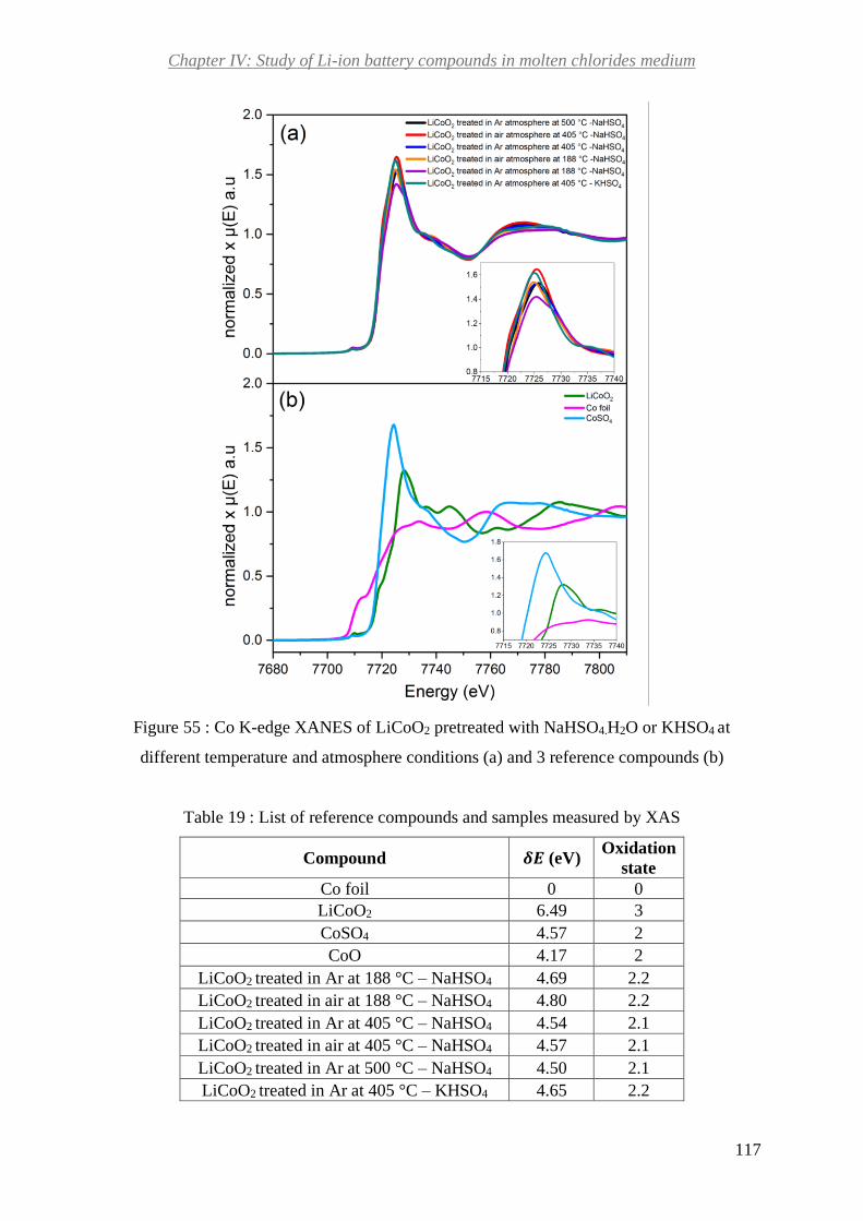
Chapter IV: Study of Li-ion battery compounds in molten chlorides medium
117
Figure 55 : Co K-edge XANES of LiCoO2 pretreated with NaHSO4.H2O or KHSO4 at
different temperature and atmosphere conditions (a) and 3 reference compounds (b)
Table 19 : List of reference compounds and samples measured by XAS
Compound 𝜹𝑬 (eV) Oxidation
state
Co foil 0 0
LiCoO2 6.49 3
CoSO4 4.57 2
CoO 4.17 2
LiCoO2 treated in Ar at 188 °C – NaHSO4 4.69 2.2
LiCoO2 treated in air at 188 °C – NaHSO4 4.80 2.2
LiCoO2 treated in Ar at 405 °C – NaHSO4 4.54 2.1
LiCoO2 treated in air at 405 °C – NaHSO4 4.57 2.1
LiCoO2 treated in Ar at 500 °C – NaHSO4 4.50 2.1
LiCoO2 treated in Ar at 405 °C – KHSO4 4.65 2.2

Chapter IV: Study of Li-ion battery compounds in molten chlorides medium
118
Figure 56 : Calibration curve employing different reference compounds (dash dots). Average
oxidation state for LiCoO2 pretreated with NaHSO4.H2O at different temperature and
atmosphere conditions
We also looked at the EXAFS part of the absorption spectra in Figure 57 (a) and (b).
The EXAFS spectra for all the samples treated strongly differ from the LiCoO2 one, Figure
57(a). A clear modification of the neighborhood of cobalt is observed for all the treatment
conditions as compared to the native LiCoO2 along with the reduction of the oxidation state.
Contrary to the analysis performed in chapter 2 with the carbonate molten salt, it is not possible
here to model the experimental spectra by a linear combination of solid reference compound
EXAFS spectra.
We compared then the Fourier Transform (FT) of these contributions with those of
CoSO4 and LiCoO2 to identify the speciation of cobalt, Figure 57 (c) and (d)). All the Fourier
transforms show a first peak, with the maximum at about 1.5 Å, that corresponds to the cobalt-
oxygen bond. This contribution is much wider for CoSO4 and all the samples than for LiCoO2.
LiCoO2 shows a very important second contribution, peak with a maximum at about 2.5 Å,

Chapter IV: Study of Li-ion battery compounds in molten chlorides medium
119
which corresponds to cobalt-cobalt bond. This contribution is absent for all the samples. It
means that for all the samples only the sphere of oxygen is visible at proximity of cobalt. The
highest contributions are always observed for the treatments in air atmosphere and at the highest
temperature. This leads to the conclusion that the optimal reduction is obtained at least at 405°C
in air atmosphere.
Figure 57 : Co K-edge EXAFS raw data for pretreatments of LiCoO2 in: Ar atmosphere (a),
air (b). EXAFS contributions of LiCoO2 reference compound (a and b). Fourier transform
(FT) of LiCoO2 pretreated in Ar (c), air (d) and reference compounds CoSO4 and LiCoO2 (c
and d)
Concerning the temperature effect, it can be seen that the structure for the 188°C
treatment seems to be a combination of different structural environment, in contrast to the
structure for 405 and 500°C treatments, as seen in Figure 57 (a). The analysis of the first
neighborhood shell, i.e. the first peak of the RDF in Figure 57 (c), by back Fourier transform
shows that the cobalt environment goes from the environment it has in LiCoO2 crystal to the

Chapter IV: Study of Li-ion battery compounds in molten chlorides medium
120
environment it has in CoSO4 crystal. At 188°C, the oscillation is intermediate between the two
structures.
Concerning the atmosphere effect, we compared the oscillation of the back Fourier
transform of the first peak as previously. It appears that the local environment of cobalt in the
sample treated under air is closer to its environment in CoSO4 than for the sample treated under
Ar. This result is consistent with the macroscopic observation where the sample treated under
air looks more homogenous.
In the same way, we compared the difference between KHSO4 and NaHSO4, and no
significant effect was observed in the first shell of neighborhood.
3.4.3. In-situ XAS measurements
For this kind of measurements, we used the same device developed for in situ XAS
described in chapter II. Here, we mixed LiCoO2 with NaHSO4.H2O in a molar proportion 1:3.
We added a portion of boron nitride to this mixture to dilute the sample and to have a good
beam transmission.
To determine the starting point of the reduction reaction of Co (III) from LiCoO2 with
NaHSO4.H2O and its kinetics, we monitored the evolution of the reaction in situ. Figure 58 (a)
shows the in situ XANES for LiCoO2 mixture with NaHSO4.H2O at different temperatures. The
main peak and the pre-edge peak are shifted toward low energy value when the temperature is
increased. A pre-edge peak is present in each case and it shifts as function of temperature. This
is an indication of a change in the oxidation state. As previously, we determine the oxidation
state and the results are listed in Table 20. The oxidation state of the samples is plotted as a
function of the temperature in Figure 58 (b). A linear decrease is observed up to 400°C followed
by a plateau. When cooling back to room temperature a slight increase occurs (Table 20). The
reaction starts at low temperature (100°C).

Chapter IV: Study of Li-ion battery compounds in molten chlorides medium
121
Figure 58 : In situ Co K-edge XANES of the mixture of LiCoO2 with NaHSO4.H2O at
different temperatures (a). Average oxidation state of the mixture of LiCoO2 with
NaHSO4.H2O evolution as function of temperature (b). RT before: at room temperature before
the heating, RT after: at room temperature after the heating

Chapter IV: Study of Li-ion battery compounds in molten chlorides medium
122
Table 20 : List of samples obtained by in-situ XAS measurements and the reference
compounds
Compound 𝜹𝑬 (eV) Oxidation
state
LiCoO2 6.49 3
Mixture LiCoO2 with NaHSO4.H2O at room
temperature before the heating 5.76 2.8
Mixture LiCoO2 with NaHSO4.H2O at 100 °C 5.41 2.7
Mixture LiCoO2 with NaHSO4.H2O at 200 °C 4.93 2.4
Mixture LiCoO2 with NaHSO4.H2O at 300 °C 4.29 2.1
Mixture LiCoO2 with NaHSO4.H2O at 400 °C 3.75 1.9
Mixture LiCoO2 with NaHSO4.H2O at 500 °C 3.70 1.8
Mixture LiCoO2 with NaHSO4.H2O at room
temperature after the heating 4.11 2.0
Figure 59 (a) and (b) show the in-situ and ex-situ EXAFS spectra for plateau
temperatures of 200°C and 400°C. EXAFS oscillations for a given temperature does not
superimpose indicating that the reaction is slow. Indeed, ex-situ samples have been heated for
12h while in-situ ones have been treated between 30 and 45 minutes at each temperature
plateau. This is more clearly evidenced at 200°C, where the in-situ EXAFS oscillations are still
characteristic of LiCoO2 while the ex-situ oscillations are a combination of LiCoO2 and final
compound form.
We compared also the Fourier Transform of in-situ and ex-situ samples, as shown on
Figure 59 (c) and (d). As it can be observed in Figure 59 (c), there is a difference between the
magnitude of each sphere of neighbors between the different conditions of measurement and
pretreatment. In fact, the treatment in air at 188°C has the highest contribution for the first
sphere of cobalt neighbors (maximum at about 1.5 Å). This peak is assigned to the cobalt-
oxygen bond. The sample at 188°C in Ar atmosphere and the in-situ measurement at 200°C
show a similar magnitude for this contribution. Moreover, the in-situ measurement shows the
characteristic of LiCoO2 second sphere contribution of neighbors, which corresponds to cobalt
one. This confirms that for the in-situ measurement at 200°C, the reduction reaction is
incomplete. Figure 59 (d) also exhibits differences between the Fourier Transform of in-situ
and ex-situ measurements. As before, the highest magnitude is observed for the pretreatment at
405°C in air atmosphere (ex-situ measurement). The lowest one is observed for the in-situ
measurement at 400°C. This can be explained by the Debye Waller factor.

Chapter IV: Study of Li-ion battery compounds in molten chlorides medium
123
Figure 59 : Comparison of Co K-edge EXAFS raw data between in- situ measurements of
mixture LiCoO2 with NaHSO4.H2O at 200°C and ex-situ measurements at 188°C (a). Their
Fourier Transform comparison in (c). Comparison of Co K-edge EXAFS raw data between
in- situ measurements of mixture LiCoO2 with NaHSO4.H2O at 400°C and ex-situ
measurements at 405°C (b). Their Fourier Transform comparison in (d)
3.5. Influence of NaHSO4.H2O on LiCoO2 solubility in molten LiCl-KCl eutectic
Cobalt dissolution between LCO with and without being pretreated with NaHSO4.H2O
was compared (Figure 60). For both cases, the voltammogram shows the presence of an anodic
and a cathodic peak. Their positions and current density can be seen in Table 21. For both
measurements the starting point was 0.8 V vs CoII/Co0 and corresponds to the OCP of one of
both systems. There is an important difference in the peaks’ width for both voltammograms.
Furthermore, the cathodic standard potentials show a difference of about 8. 10-2 V. Both aspects
may be explained by a difference in cobalt Co(II) speciation in the medium.

Chapter IV: Study of Li-ion battery compounds in molten chlorides medium
124
As the current density of both cathodic peaks is compared, pretreated LCO peak shows
a current density about 10 times higher than the one without the pretreatment. As peaks current
density is linked to dissolved cobalt concentration (Eq. 33), it can be concluded that
hydrogenosulfate NaHSO4.H2O increases the solubility of cobalt from LCO in eutectic LiCl-
KCl. This result is explained by the reduction of Co(III) in this compound into Co(II), which
can be then dissolved in molten chloride as Co+II. This is in accordance with the literature as
Delarue has previously shown that Co(II) in cobalt oxide is dissociated into Co+II in this
medium136.
Figure 60 : Voltammogram comparison for LiCoO2 (LCO) in molten eutectic LiCl-KCl on
glassy carbon working electrode at 405°C (8h), 1 atm Ar with and without pretreatment.
Graphite and cobalt used as counter and reference electrodes. Introduced cobalt concentration
equal to 1.10-5 mol.cm-3
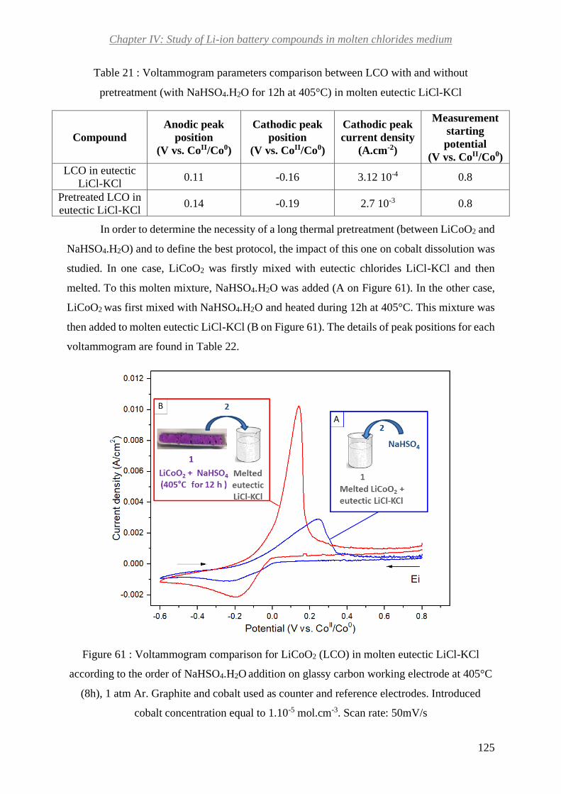
Chapter IV: Study of Li-ion battery compounds in molten chlorides medium
125
Table 21 : Voltammogram parameters comparison between LCO with and without
pretreatment (with NaHSO4.H2O for 12h at 405°C) in molten eutectic LiCl-KCl
Compound
Anodic peak
position
(V vs. CoII/Co0)
Cathodic peak
position
(V vs. CoII/Co0)
Cathodic peak
current density
(A.cm-2)
Measurement
starting
potential
(V vs. CoII/Co0)
LCO in eutectic
LiCl-KCl 0.11 -0.16 3.12 10-4 0.8
Pretreated LCO in
eutectic LiCl-KCl 0.14 -0.19 2.7 10-3 0.8
In order to determine the necessity of a long thermal pretreatment (between LiCoO2 and
NaHSO4.H2O) and to define the best protocol, the impact of this one on cobalt dissolution was
studied. In one case, LiCoO2 was firstly mixed with eutectic chlorides LiCl-KCl and then
melted. To this molten mixture, NaHSO4.H2O was added (A on Figure 61). In the other case,
LiCoO2 was first mixed with NaHSO4.H2O and heated during 12h at 405°C. This mixture was
then added to molten eutectic LiCl-KCl (B on Figure 61). The details of peak positions for each
voltammogram are found in Table 22.
Figure 61 : Voltammogram comparison for LiCoO2 (LCO) in molten eutectic LiCl-KCl
according to the order of NaHSO4.H2O addition on glassy carbon working electrode at 405°C
(8h), 1 atm Ar. Graphite and cobalt used as counter and reference electrodes. Introduced
cobalt concentration equal to 1.10-5 mol.cm-3. Scan rate: 50mV/s

Chapter IV: Study of Li-ion battery compounds in molten chlorides medium
126
Table 22 : Voltammogram parameters comparison between both conditions of NaHSO4.H2O
addition shown on Figure 61
Voltammogram
on figure 61
Anodic peak
position
(V vs. CoII/Co0)
Cathodic peak
position
(V vs. CoII/Co0)
Cathodic peak
current density
(A.cm-2)
Measurement
starting
potential
(V vs. CoII/Co0)
A 0.24 -0.22 1.1 10-3 0.8
B 0.14 -0.21 2.4 10-3 0.8
When comparing both voltammograms, we observed a difference in the shape of both
cathodic and anodic peaks and the distance between them. In fact, A shows a wider anodic peak
than B. Furthermore, a difference of 0.009 V appears between both cathodic potentials. Both
variations may be explained by a difference of Co(II) speciation in the system. Regarding the
distance between voltammograms cathodic and anodic peaks, it is higher in the case of A. This
may imply that for A the redox reaction is limited by the charge transfer, while for B it is limited
by the mass transport. This leads to the conclusion that cobalt cations are more available around
the electrode in B.
When comparing both cathodic peaks, it can be seen that B shows a current density two
times higher than A. It means, there is twice cobalt dissolution when the thermal pretreatment
is present (LiCoO2 mixed with NaHSO4.H2O for 12h at 405°C), confirming its impact on
LiCoO2 dissolution in the melt. As a consequence, the protocol adopted for the next studies
included this thermal step as the first one.
Hydrogenosulfates addition approach was also tested on molten carbonates. Here
previously pretreated LiCoO2 was mixed with molten carbonates before the heating (using
method B in Figure 61). The results of both systems, with and without pretreatment, are shown
in Figure 62. As observed, hydrogenosulfates pretreatment does not increase cobalt dissolution
from LiCoO2 in molten carbonates. Cathodic and anodic peaks are quite similar in both cases.
This result was expected as cobalt dissolved in form of Co(II) in molten carbonates, as seen in
chapter II from XANES results.

Chapter IV: Study of Li-ion battery compounds in molten chlorides medium
127
Figure 62 : Voltammogram comparison for LiCoO2 (LCO) in molten eutectic Li2CO3-
Na2CO3-K2CO3 on silver wire working electrode at 450°C (168h), 1 atm Ar with and without
pretreatment. Graphite and cobalt used as counter and reference electrodes. Introduced cobalt
concentration equal to 2.5 10-5 mol.cm-3.
3.6. Electrochemical study of LiCoO2 pretreated with NaHSO4.H2O in molten LiCl-
KCl eutectic
Quantifying dissolution
The voltammogram in Figure 63 shows the redox system observed in this case. For the
details about electrode preparation, they are given in section 2.2 of this chapter. The cathodic
and anodic peaks are present at -0,504 ± 0.005 and -0,371 ± 0,004 V. vs AgI/Ag0 respectively.
The measurement was done from the OCP (-0.1 V. vs AgI/Ag0) towards the cathodic potentials
and backwards. As before, there is the same negative potential shift, about 0.2V, compared to
the literature. The same problems encountered with the reference electrode for LiCoO2 (Figure
50) appeared in this case.

Chapter IV: Study of Li-ion battery compounds in molten chlorides medium
128
Figure 63 : Voltammograms of the solution containing LCO pretreated with NaHSO4.H2O in
eutectic molten LiCl-KCl on gold wire working electrode at 405°C (for 48h), 1 atm Ar (a). Its
cathodic peak current density evolution in function of cyclic voltammetry scan rate square
root (b). Graphite and AgI/Ag0 were used as counter and reference electrodes, respectively.
Cobalt concentration introduced equal to 5.10-5 mol.cm-3
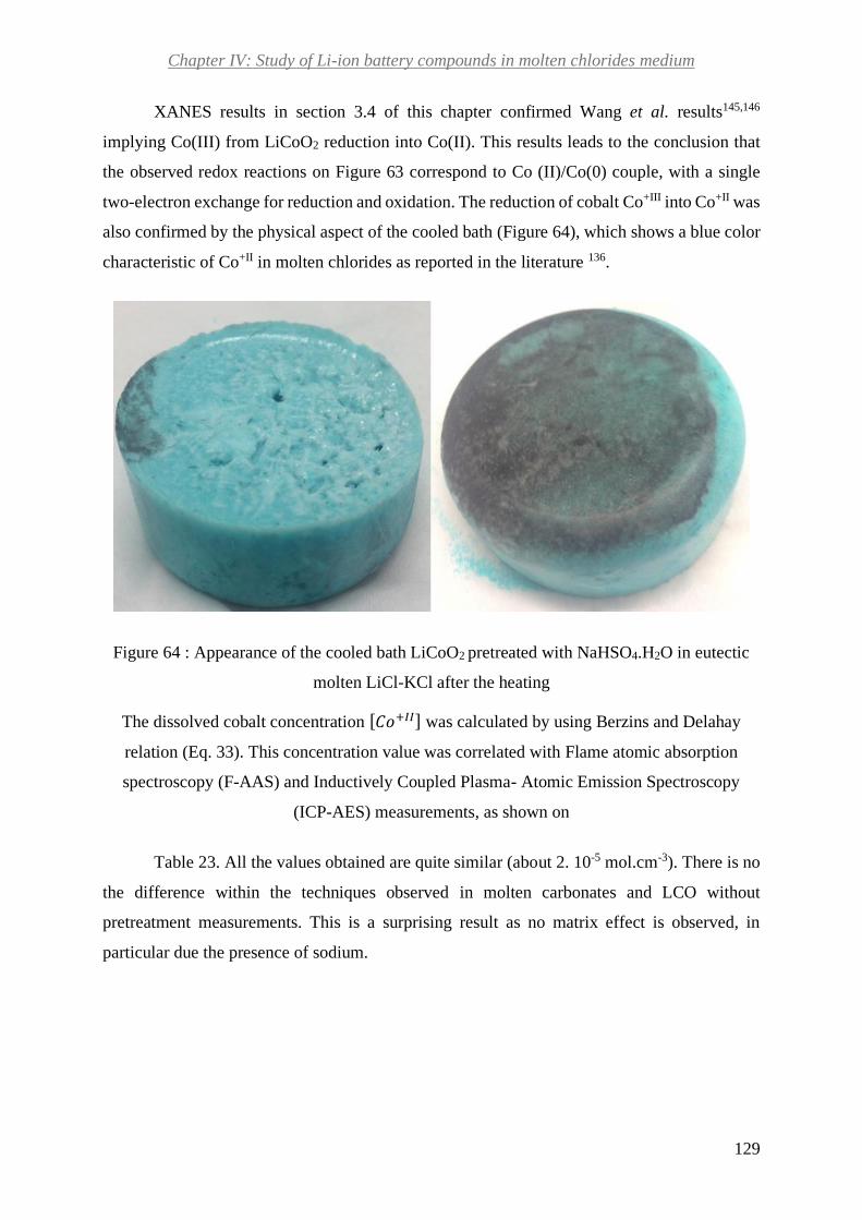
Chapter IV: Study of Li-ion battery compounds in molten chlorides medium
129
XANES results in section 3.4 of this chapter confirmed Wang et al. results145,146
implying Co(III) from LiCoO2 reduction into Co(II). This results leads to the conclusion that
the observed redox reactions on Figure 63 correspond to Co (II)/Co(0) couple, with a single
two-electron exchange for reduction and oxidation. The reduction of cobalt Co+III into Co+II was
also confirmed by the physical aspect of the cooled bath (Figure 64), which shows a blue color
characteristic of Co+II in molten chlorides as reported in the literature 136.
Figure 64 : Appearance of the cooled bath LiCoO2 pretreated with NaHSO4.H2O in eutectic
molten LiCl-KCl after the heating
The dissolved cobalt concentration [𝐶𝑜+𝐼𝐼] was calculated by using Berzins and Delahay
relation (Eq. 33). This concentration value was correlated with Flame atomic absorption
spectroscopy (F-AAS) and Inductively Coupled Plasma- Atomic Emission Spectroscopy
(ICP-AES) measurements, as shown on
Table 23. All the values obtained are quite similar (about 2. 10-5 mol.cm-3). There is no
the difference within the techniques observed in molten carbonates and LCO without
pretreatment measurements. This is a surprising result as no matrix effect is observed, in
particular due the presence of sodium.

Chapter IV: Study of Li-ion battery compounds in molten chlorides medium
130
Table 23 : Results of dissolved cobalt concentration [𝐶𝑜+𝐼𝐼] for LiCoO2 pretreated with
NaHSO4.H2O in eutectic molten LiCl-KCl obtained by electrochemistry and flame
spectroscopy
Cathode
material
Slope
(A.cm-2.V-1/2.s1/2)
Measured by CV
[𝑪𝒐+𝑰𝑰] (mol.cm-3)
Measured by
F-AAS [𝑪𝒐+𝑰𝑰] (mol.cm-3)
Measured by
ICP.[𝑪𝒐+𝑰𝑰] (mol.cm-3)
LCO
pretreated with
NaHSO4.H2O
7. 10-2 ± 0.40 10-2 2.5 10-5 2.10-5 2.310-5
When comparing both dissolution values obtained for LCO with (this section) and
without pretreatment (section 3.3), we can conclude that dissolved cobalt concentration is about
10 times more important.
Cobalt electrodeposition from pretreated LiCoO2 with NaHSO4.H2O in molten chlorides
LiCl-KCl eutectic
Once that pretreated LiCoO2 with NaHSO4.H2O was studied by cyclic voltammetry, the
possibility of recovering metallic cobalt by electrolysis from this medium was investigated. The
following section shows the results of the deposit obtained and the analysis of the
electrodeposited product. Figure 65 (a) shows the chronoamperogramm obtained during the
electrodeposition.
From the beginning of the electrolysis, there is a continuous increase in the current. It
indicates that there is a constant rise of the electrode surface area, and leads to the conclusion
that the deposit corresponds to a conductor material. The deposit is a solid with black and blue
colors as observed in Figure 65 (b). The blue color can be attributed to the solvent (where Co(II)
is dissolved). For this reason, we rinsed it with distilled water and dried the deposit before
analyzing it.

Chapter IV: Study of Li-ion battery compounds in molten chlorides medium
131
Figure 65 : Chronoamperogramm during the electrolysis on gold wire electrode (a). Photo of
the deposit (b). Graphite and AgI/Ag0 were used as counter and reference electrodes,
respectively. The potential steps from -0.10 V to -0.65 V vs. AgI/Ag0
Figure 66 shows the deposit X-ray diffraction (XRD) measurement, for the first
electrode set-up tested. The X-ray diffraction measurement in Figure 66 confirms that the
recovered matter is constituted of metallic cobalt by the presence of the two principal peaks of
it at 41.54 and 47.41 °. This implies that the recovery of metallic cobalt in molten chlorides
after pretreating it with NaHSO4.H2O is possible by electrochemical means.
Other metals are also observed on the deposit. In fact, silver, gold and copper seem to
be present. In order to confirm the presence of these impurities Energy-dispersive X-ray
spectroscopy (EDX) was used.

Chapter IV: Study of Li-ion battery compounds in molten chlorides medium
132
Figure 66 : XRD of deposited matter after washing, from LiCoO2 pretreated with
NaHSO4.H2O in molten eutectic LiCl-KCl on gold wire working electrode. Graphite and
AgI/Ag0 were used as counter and reference electrodes, respectively
Figure 67 shows cartographies obtained for each deposit constituent by this technique.
The cartographies confirm that the electrodeposited matter recovered is constituted by cobalt.
Furthermore, they confirm the presence of silver, gold and cooper pollutions. The existence of
chlorides and oxygen compounds are also identified by EDX measurement. The presence of
silver can be explained by a leak of the reference electrode. The copper observed can be
explained by the fall of the counter electrode which is constituted by a graphite rod connected
to a copper wire. The gold presence can be attributed to an attack of the working electrode.

Chapter IV: Study of Li-ion battery compounds in molten chlorides medium
133
Figure 67 : Energy-dispersive X-ray spectroscopy (EDX) cartographies of the deposit, from
LiCoO2 pretreated with NaHSO4.H2O in molten eutectic LiCl-KCl on gold wire working
electrode. Measurements were done on a carbon support, at room atmosphere and
temperature. Graphite and AgI/Ag0 were used as counter and reference electrodes,
respectively
The quantities of each element are shown in the Table 24 below. We do not consider the
portion of carbon detected, as the support of the sample for EDX is made of it. As shown, the
cobalt is the element present in the highest weight % in the sample. The presence of a non-
depreciable quantity of copper and silver is also confirmed, which is respectively 6.9 and 15.4
weight %. Gold presence was also confirmed in a low percentage of 0.4 weight percent.
Furthermore, the estimated quantity of oxygen in the electrodeposited matter may be explained
by the fact that the measurement was done at room atmosphere and the deposit can be easily
oxidized.
Table 24 : Weight composition of electrodeposited from LiCoO2 pretreated with
NaHSO4.H2O in molten eutectic LiCl-KCl on gold wire working electrode. Graphite and
AgI/Ag0 were used as counter and reference electrodes, respectively
O
% weight
Cl
%
weight
Co
%
weight
Cu
%
weight
Ag
%
weight
Au
%
weight
Mean 30.2 0.1 46.6 6.9 15.4 0.4

Chapter IV: Study of Li-ion battery compounds in molten chlorides medium
134
From these results, it was concluded that several optimizations of the electrodes set-up
were needed. AgI/Ag0 reference electrode was not the most suitable to obtain a deposit without
pollutions. Furthermore, an optimization in the counter electrode conception was needed in
order to prevent the counter electrode and its connecting wire from falling in the molten melt.
Finally, it seemed to be necessary to test in the future other materials as working electrodes as
gold was attacked during the electrolysis. First, the silver reference was changed by a cobalt
bar as reference electrode and the counter electrode connector wire changed by a steel rod.
The Figure 68 (a) shows the chronoamperogramm obtained during the electrolysis, for
the second electrode set-up tested. There is an abrupt increase in the current at the beginning of
the electrolysis. Then, there is a continuous rise of the current due to the increase in the electrode
surface. This trend is observed until about 4500 s, where a plateau is observed. This is a sticking
result as the deposit is expected to be a conductor material.
Figure 68 : Chronoamperogramm during the electrolysis on gold plate electrode (a). Photo of
the recovered matter (b). Graphite and cobalt were used as counter and reference electrodes
respectively. The potential steps from 0.50 V to -0.30 vs. CoII/Co0.
The recovered matter has the same aspect of the previous recovered matter (solid with
black and blue colors), as seen in Figure 68 (b). The Figure 69 shows the XRD measurement
obtained for the electrodeposited matter. As it is observed, the deposit is constituted by cobalt
and gold essentially. As a consequence, it can be concluded that the optimization of electrodes

Chapter IV: Study of Li-ion battery compounds in molten chlorides medium
135
set-up was efficient because there are no more copper and silver pollutions observed.
Furthermore, these results confirm once again that metallic cobalt can be recovered by
electrodeposition from this system.
Figure 69 : XRD of deposited matter from LiCoO2 pretreated with NaHSO4.H2O in molten
eutectic LiCl-KCl on gold plate working electrode. Graphite and cobalt were used as counter
and reference electrodes, respectively
As before, we analyzed the deposited matter by EDX to determine the composition of
it. Figure 70 exhibits the cartographies of each element present in the recovered matter. They
confirmed the presence of gold and cobalt already detected by XRD measurement. The presence
of gold confirms the attack of it during the electrolysis. As before, the presence of oxygen can
be attributed to the possible oxidation of the deposit in room atmosphere. The quantities of each
element were estimated by EDX as shown in Table 25.

Chapter IV: Study of Li-ion battery compounds in molten chlorides medium
136
Table 25 : Weight composition of electrodeposited from LiCoO2 pretreated with
NaHSO4.H2O in molten eutectic LiCl-KCl on gold plate working electrode. Graphite and
cobalt were used as counter and reference electrodes, respectively
O
% weight
Cl
% weight
K
% weight
Co
% weight
Au
% weight
Mean 16.2 0.6 0.1 78.6 4.5
Cobalt is the element with the highest ratio on the deposit, about 78.6 weight %. The presence
of a non-depreciable quantity of gold, about 4.5 weight %, is also detected.
Figure 70 : Energy-dispersive X-ray spectroscopy (EDX) cartographies of the deposit, from
LiCoO2 pretreated with NaHSO4.H2O in molten eutectic LiCl-KCl on gold plate working
electrode. Measurements done on a carbon support and at room atmosphere and temperature.
Graphite and cobalt were used as counter and reference electrodes, respectively
We also characterized the deposited matter by Scanning Electron Microscopy (SEM) as
shown in Figure 71. The deposited matter appears to have the form of leaf trees of different
sizes and forms. In some cases, they agglomerate to form larger particles. These leaves are not
constituted of a single element but cobalt appears to be the preponderant constituent of them.
Furthermore, the particles do not appear to be distributed uniformly.
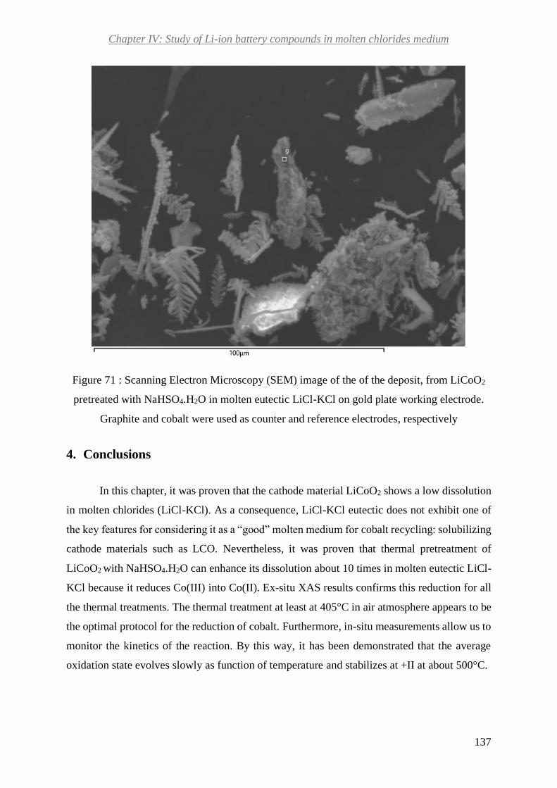
Chapter IV: Study of Li-ion battery compounds in molten chlorides medium
137
Figure 71 : Scanning Electron Microscopy (SEM) image of the of the deposit, from LiCoO2
pretreated with NaHSO4.H2O in molten eutectic LiCl-KCl on gold plate working electrode.
Graphite and cobalt were used as counter and reference electrodes, respectively
4. Conclusions
In this chapter, it was proven that the cathode material LiCoO2 shows a low dissolution
in molten chlorides (LiCl-KCl). As a consequence, LiCl-KCl eutectic does not exhibit one of
the key features for considering it as a “good” molten medium for cobalt recycling: solubilizing
cathode materials such as LCO. Nevertheless, it was proven that thermal pretreatment of
LiCoO2 with NaHSO4.H2O can enhance its dissolution about 10 times in molten eutectic LiCl-
KCl because it reduces Co(III) into Co(II). Ex-situ XAS results confirms this reduction for all
the thermal treatments. The thermal treatment at least at 405°C in air atmosphere appears to be
the optimal protocol for the reduction of cobalt. Furthermore, in-situ measurements allow us to
monitor the kinetics of the reaction. By this way, it has been demonstrated that the average
oxidation state evolves slowly as function of temperature and stabilizes at +II at about 500°C.

Chapter IV: Study of Li-ion battery compounds in molten chlorides medium
138
Moreover, it was shown that when using this thermal pretreatment, it is possible to
recover metallic cobalt by electrochemical means on gold working electrode, where cobalt
constitutes 78.6 weight% of the deposit. Therefore, this approach is promising for the future.
The pretreatment impact on other cathode materials NCA and NMC dissolution in molten LiCl-
KCl appears to be one of the steps to follow.
Regarding the experimental set-up presented in this chapter, it can be concluded that
cobalt pseudo-reference is more practical than AgI/Ag0 as it prevents the pollution of the deposit
by silver. Looking for another working electrode material is necessary in the future, as gold
electrode is attacked during the electrolysis. Tungsten can be suggested as a candidate to be
tested. For matter of time, this electrode was not tested for electrolysis during this project.
It is important to note that regarding the recovery of metallic cobalt from Co3O4, new
approaches have been developed recently by using non miscible molten mixtures, containing
one alkali chlorides phase. Amietszajew et al. studied Co3O4 in this kind of system. The mixture
was composed of a borate phase (Na2O-2B2O3) and a chloride one (NaCl) 147. In the oxide melt
Co3O4 was dissolved and then transported to the oxide/chloride interface and finally transferred
to the chloride phase. The results from this work showed that cobalt form Co3O4 is present in
the molten media at two oxidation states +II and +III. Furthermore, it was proven that 99% pure
metallic cobalt can be recovered by electrolysis from this medium. This kind of system could
be another alternative to explore in the future.

Ruiz Onofre Patricia Nathaly – Thèse de doctorat - 2019
139
General conclusions and perspectives
“Il faut faire de la vie un rêve et
d’un rêve une réalité.”
Marie Curie

Ruiz Onofre Patricia Nathaly – Thèse de doctorat - 2019
140
Li-ion batteries are composed of organic and inorganic compounds. Molten salts
systems are widely applied as solvents for different metals recovery and manufacturing, by
electrolysis. Furthermore, some molten systems have the capacity of trapping and/or
decomposing hazardous organic compounds. From these points of view, they seem promising
candidates for Li-ion batteries recycling. The main objective of this work was to explore and
analyze the feasibility of recycling Li-ion battery organic and inorganic compounds (cathode
materials) in one molten system. Among the different inorganic compounds in Li-ion battery
our aim was particularly to understand cobalt behavior in the molten media and exploring the
possibility of recovering it by electrolysis. We selected two molten media during this project:
molten carbonates (Li2CO3-Na2CO3-K2CO3) and molten chlorides (LiCl-KCl).
In this context, a good solvent should fulfill three main requirements. First of all, it must
show a good dissolution of cathode oxides and particularly of cobalt oxide. Secondly, it should
ensure the possibility of recovering cobalt by electrochemical means. Finally, the third
condition consists in the good decomposition of Li-ion battery organic compounds such as:
binders, separators.
Concerning cobalt speciation, XAS experiments in molten carbonates highlights that
cobalt is reduced from +III to +II in molten Li2CO3-Na2CO3-K2CO3 for LCO, NCA and NMC
cathode materials. Moreover, results show that for LCO, it is transformed into CoO, which
remains stable during all the XAS experiment. If we consider the possibility of valorizing this
compound, it would be difficult as industries generally use cobalt carbonate or sulfate as
precursors for their applications.
Regarding cobalt dissolution, we establish that cobalt from cathode materials LCO,
NCA and NMC dissolution kinetics in molten carbonates is slow. Cyclic voltammetry, flame
spectroscopy and ICP-AES results reveal that its maximal dissolution in this medium is low.
XRD results on the deposit from electrolysis in this medium, demonstrate that the dissolution
of cobalt is too low for its recovery by electrochemical means. Indeed, no cobalt is detected in
the recovered matter. With respect to organic compounds recycling, preliminary results show
the decomposition of Li-ion battery binders CMC, PVDF and separator PP in different
hydrocarbons. From all these results, the molten Li2CO3-Na2CO3-K2CO3 eutectic seems not to
be the most suitable for cobalt recovery but a promising alternative to explore the future
regarding organic compounds valorization.

Ruiz Onofre Patricia Nathaly – Thèse de doctorat - 2019
141
The results in molten chlorides also reveal a low dissolution of cobalt from cathode
material LCO, confirming that Co(III) form is very poorly soluble in this medium. Nevertheless,
Cyclic voltammetry, flame spectroscopy and ICP-AES results demonstrate that a thermal
pretreatment of cathode material LCO with NaHSO4.H2O enhances cobalt solubility about 10
times in molten chlorides. XAS results confirm the reduction of Co(III) into Co(II) and the slow
evolution of cobalt oxidation state as function of temperature. Cobalt electrodeposition success
has been proven for LCO in molten chlorides when we apply a thermal pretreatment of cathode
material with NaHSO4.H2O previously. Indeed, EDX and XRD results highlight that cobalt is
the predominant element in the deposit with at least 46% weight. For the study in molten
chlorides, the choice of electrode and their fabrication was a challenge needed to be addressed.
XRD and EDX results reveal that leaks are constantly observed for AgI/Ag0 leading to the
presence of pollution in the deposit. Results demonstrate that gold working electrode can be
used for achieving cobalt recovering in this medium but no without been attacked.
During this work we developed a whole set-up for measuring the absorption spectrum
of cobalt in molten salts. We demonstrate its reliability for performing measurements at 550°C
for several hours.
This thesis work opens several routes for the future:
With respect to XAS results in molten carbonates, the need of new measurements in the
same conditions of electrochemical measurements is necessary in the future, to confirm the
formation of CoO small aggregates in the bath and the reduction of a portion of Co (II) into
metallic cobalt in molten carbonates. Furthermore, the in-situ XAS measurements of
electrolysis could be carried out in the same device developed during this project. The addition
of electrodes can be done in this device design. Moreover, the cell design developed during this
project could be manufactured in the future in boron nitride for in-situ studies in
hydrogenosulfates, as we detected no interaction between it and the sample mixture (cobalt +
hydrogenosulfates).
Regarding cobalt recovery by electrolysis, molten chlorides LiCl-KCl are a suitable
system but only after pretreating the cathode material with hydrogenosulfates. The
electrochemical characterization in molten LiCl-KCl of the other pretreated cathodes NCA and
NMC should be continued in the future as the next step. Then, the whole Li-ion battery cathodes
(cathode + current collector + binder) behavior in the salt could be tested. Furthermore, testing

Ruiz Onofre Patricia Nathaly – Thèse de doctorat - 2019
142
Li-ion battery organic compounds (separators and binders) could be another aspect to be
explored.
The pretreatment of cathode materials with hydrogenosulfates should be continued in at
air atmosphere and at least at 405°C as it shows the best reduction of cobalt. Concerning the
electrodes used for the recovery, other material should be tested because gold electrode is
attacked during the electrolysis. Testing tungsten electrode in a first place could be one of the
alternatives.
In what concerns the recycling of Li-ion battery compounds, new molten mixtures could
be explored in the future. The solution for recycling organic and inorganic compounds might
not include one molten salt system but at least two molten salts. From this point of view,
exploring non miscible mixtures, containing one alkali chlorides phase could be another
alternative to explore.

Ruiz Onofre Patricia Nathaly – Thèse de doctorat - 2019
143
References
(1) Yoo, H. D.; Markevich, E.; Salitra, G.; Sharon, D.; Aurbach, D. On the Challenge of
Developing Advanced Technologies for Electrochemical Energy Storage and Conversion.
Mater. Today 2014, 17 (3), 110–121. https://doi.org/10.1016/j.mattod.2014.02.014.
(2) Xianlai, Z.; Jinhui, L.; Narendra, S. Recycling of Spent Lithium-Ion Battery: A Critical
Review. Crit. Rev. Environ. Sci. Technol. 2014, 44, 1129–1165.
https://doi.org/10.1080/10643389.2013.763578.
(3) Gaines, L.; Richa, K.; Spangenberger, J. Key Issues for Li-Ion Battery Recycling. MRS
Energy Sustain. 2018, 5, 1–14. https://doi.org/10.1557/mre.2018.13.
(4) Nelson, P. A.; Gallagher, K. G.; Bloom, I.; Dees, D. W. Modeling the Performance and Cost
of Lithium-Ion Batteries for Electric-Drive Vehicles,; Illinois, 2011.
https://doi.org/10.2172/1027714.
(5) McKinsey & Company. Lithium and Cobalt- a Tale of Two Commodities; 2018.
(6) Avicenne Energy. Battery Market Development for Consumer Electronics, Automotive, and Industrial : Materials Requirements and Trends; 2015.
(7) Berckmans, G.; Messagie, M.; Smekens, J.; Omar, N.; Vanhaverbeke, L.; Mierlo, J. Cost
Projection of State of the Art Lithium-Ion Batteries for Electric Vehicles up to 2030; 2017;
Vol. 10. https://doi.org/10.3390/en10091314.
(8) Gaines, L.; Sullivan, J.; Burnham, A. Life-Cycle Analysis for Lithium-Ion Battery Production
and Recycling; 2011.
(9) Nitta, N.; Wu, F.; Lee, J. T.; Yushin, G. Li-Ion Battery Materials: Present and Future. J.
Mater. today 2015, 18, 252–264.
(10) Freitas, M. B. J. G.; Garcia, E. M. Electrochemical Recycling of Cobalt from Cathodes of
Spent Lithium-Ion Batteries. J. Power Sources 2007, 171 (2), 953–959.
https://doi.org/10.1016/j.jpowsour.2007.07.002.
(11) Natarajan, S.; Aravindan, V. Recycling Strategies for Spent Li-Ion Battery Mixed Cathodes.
ACS Energy Lett. 2018, 3 (9), 2101–2103. https://doi.org/10.1021/acsenergylett.8b01233.
(12) ALBERMARLE. Global Lithium Market Outlook; 2016.
(13) Avicenne Energy. Lithium-Ion Battery Raw Material Supply and Demand 2017-2025; 2018.
(14) Statista. Countries with the largest Nickel reserves Worldwide in 2017, by country (in
million metric tons) https://www.statista.com/statistics/273634/nickel-reserves-worldwide-
by-country/.
(15) Statista. Countries with the largest Cobalt reserves Worldwide in 2017, by country (in metric
tons) https://www.statista.com/statistics/264930/global-cobalt-reserves/.
(16) Statista. Countries with the largest Lithium reserves worldwide in 2017 (in metric tons)
https://www.statista.com/statistics/268790/countries-with-the-largest-lithium-reserves-
worldwide/%0A.
(17) European Commission. Methodology for Establishing the EU List of Critical Raw Materials.
https://doi.org/10.2873/769526.
(18) European Commission. Report on Critical Raw Materials and the Circular Economy; 2018.
https://doi.org/10.1097/PPO.0b013e3181b9c5d5.
(19) U.S. Department of the Interior. Draft List of 35 Minerals Deemed Critical to U.S. National
Security and the Economy https://www.doi.gov/pressreleases/interior-seeks-public-

Ruiz Onofre Patricia Nathaly – Thèse de doctorat - 2019
144
comment-draft-list-35-minerals-deemed-critical-us-national.
(20) Lubaba, C.; Banza, N.; Nawrot, T. S.; Al., E. High Human Exposure to Cobalt and Other
Metals in Katanga, a Mining Area of the Democratic Republic of Congo. Environ. Res. 2009,
109 (6), 745–752. https://doi.org/10.1016/j.envres.2009.04.012.
(21) Petroff, A. Carmakers and big tech struggle to keep batteries free from child labor
http://money.cnn.com/2018/05/01/technology/cobalt-congo-child-labor-car-smartphone-
batteries/index.html.
(22) Kim, J. H.; Gibbs, J.; Howe, P. D.; Wood, M. Concise International Chemical Assessment
Document 69: Cobalt and Inorganic Cobalt Compounds. World Heal. Organ. 2006, 1–93.
(23) Bonhoure, J.; Mahy, G.; Lange, B.; Colinet, G.; Séleck, M.; Shutcha, M.; Faucon, M.-P.;
Decrée, S.; Pourret, O. Assessment of Soil Metal Distribution and Environmental Impact of
Mining in Katanga (Democratic Republic of Congo). Appl. Geochemistry 2016, 64, 43–55.
https://doi.org/10.1016/j.apgeochem.2015.07.012.
(24) Chemical properties of cobalt - Health effects of cobalt - Environmental effects of cobalt
http://www.lenntech.com/periodic/elements/co.htm.
(25) Cobalt price evolution https://www.lme.com/Metals/Minor-metals/Cobalt. Consulted on
January 2019.
(26) Avicenne Energy. The Rechargeable Battery Market and Main Trends 2012-2025; 2017.
(27) Gaines, L. To Recycle, or Not to Recycle, That Is the Question: Insights from Life-Cycle
Analysis. MRS Bull. 2012, 37 (4), 333–338. https://doi.org/10.1557/mrs.2012.40.
(28) Kong, L.; Li, C.; Jiang, J.; Pecht, M. G. Li-Ion Battery Fire Hazards and Safety Strategies.
Energies 2018, 11 (9), 1–11. https://doi.org/10.3390/en11092191.
(29) Tanong, K.; Coudert, L.; Mercier, G.; Blais, J. F. Recovery of Metals from a Mixture of
Various Spent Batteries by a Hydrometallurgical Process. J. Environ. Manage. 2016, 181,
95–107. https://doi.org/10.1016/j.jenvman.2016.05.084.
(30) Chagnes, A.; Pospiech, B. A Brief Review on Hydrometallurgical Technologies for
Recycling Spent Lithium-Ion Batteries. J. Chem. Technol. Biotechnol. 2013, 88 (7), 1191–
1199. https://doi.org/10.1002/jctb.4053.
(31) Kang, J.; Senanayake, G.; Sohn, J.; Shin, S. M. Recovery of Cobalt Sulfate from Spent
Lithium Ion Batteries by Reductive Leaching and Solvent Extraction with Cyanex 272.
Hydrometallurgy 2010, 100 (3–4), 168–171.
https://doi.org/10.1016/j.hydromet.2009.10.010.
(32) Bernades, A. M.; Espinosa, D. C. R.; Ténorio, J. Recycling of Batteries: A Review of Current
Processes and Technologies. J. Power Sources 2004, 130, 291–298.
(33) Sun, F.; Liu, J.; Li, L.; Chen, R.; Wu, F. Preparation of LiCoO2 Films from Spent Lithium-
Ion Batteries by a Combined Recycling Process. Hydrometallurgy 2011, 108 (3–4), 220–
225. https://doi.org/10.1016/j.hydromet.2011.04.013.
(34) Schaeffer, N.; Gras, M.; Passos, H.; Mogilireddy, V.; Mendonça, C.; Pereira, E.; Chainet,
E.; Billard, I.; Coutinho, J.; Papaiconomou, N. Synergistic Aqueous Biphasic Systems: A
New Paradigm for the “One-Pot” Hydrometallurgical Recovery of Critical Metals. ACS
Sustain. Chem. Eng. 2018, 1–33. https://doi.org/10.1021/acssuschemeng.8b05754.
(35) Gras, M.; Papaiconomou, N.; Schaeffer, N.; Chainet, E.; Tedjar, F.; Coutinho, J.; Billard, I.
Ionic-Liquid-Based Acidic Aqueous Biphasic Systems for Simultaneous Leaching and
Extraction of Metallic Ions. Angew. Chemie - Int. Ed. 2018, 57 (6), 1563–1566.
https://doi.org/10.1002/anie.201711068.
(36) Chen, X.; Ma, H.; Luo, C.; Zhou, T. Recovery of Valuable Metals from Waste Cathode

Ruiz Onofre Patricia Nathaly – Thèse de doctorat - 2019
145
Materials of Spent Lithium-Ion Batteries Using Mild Phosphoric Acid. J. Hazard. Mater.
2017, 326, 77–86. https://doi.org/10.1016/j.jhazmat.2016.12.021.
(37) Zeng, X.; Li, J.; Shen, B. Novel Approach to Recover Cobalt and Lithium from Spent
Lithium-Ion Battery Using Oxalic Acid. J. Hazard. Mater. 2015, 295 (2015), 112–118.
https://doi.org/10.1016/j.jhazmat.2015.02.064.
(38) Li, L.; Ge, J.; Wu, F.; Chen, R.; Chen, S.; Wu, B. Recovery of Cobalt and Lithium from
Spent Lithium Ion Batteries Using Organic Citric Acid as Leachant. J. Hazard. Mater. 2010,
176 (1–3), 288–293. https://doi.org/10.1016/j.jhazmat.2009.11.026.
(39) Zeng, G.; Deng, X.; Luo, S.; Luo, X.; Zou, J. A Copper-Catalyzed Bioleaching Process for
Enhancement of Cobalt Dissolution from Spent Lithium-Ion Batteries. J. Hazard. Mater.
2012, 199–200, 164–169. https://doi.org/10.1016/j.jhazmat.2011.10.063.
(40) Chen, S.; Wang, J.; Xin, B.; Huang, Q.; Niu, Z.; Yang, Y. Metallic Ions Catalysis for
Improving Bioleaching Yield of Zn and Mn from Spent Zn-Mn Batteries at High Pulp
Density of 10%. J. Hazard. Mater. 2015, 298, 170–177.
https://doi.org/10.1016/j.jhazmat.2015.05.038.
(41) Gratz, E.; Sa, Q.; Apelian, D.; Wang, Y. A Closed Loop Process for Recycling Spent Lithium
Ion Batteries. J. Power Sources 2014, 262, 255–262.
https://doi.org/10.1016/j.jpowsour.2014.03.126.
(42) Heelan, J.; Gratz, E.; Zheng, Z.; Wang, Q.; Chen, M.; Apelian, D.; Wang, Y. Current and
Prospective Li-Ion Battery Recycling and Recovery Processes. Jom 2016, 68 (10), 2632–
2638. https://doi.org/10.1007/s11837-016-1994-y.
(43) Shi, Y.; Chen, G.; Chen, Z. Effective Regeneration of LiCoO2 from Spent Lithium-Ion
Batteries: A Direct Approach towards High-Performance Active Particles. Green Chem.
2018, 20 (4), 851–862. https://doi.org/10.1039/c7gc02831h.
(44) Zhu, S.; Qin, Y.; Zhang, J. Renovation of Lithium Cobalt Oxide from Spent Lithium Ion
Batteries by an Aqueous Pulsed Discharge Plasma. Int. J. Electrochem. Sci. 2016, 11 (7),
6403–6411. https://doi.org/10.20964/2016.07.103.
(45) Zhang, Z.; He, W.; Li, G.; Xia, J.; Hu, H.; Huang, J. Ultrasound-Assisted Hydrothermal
Renovation of LiCoO2 from the Cathode of Spent Lithium-Ion Batteries. Int. J. Electrochem.
Sci. 2014, 9 (7), 3691–3700.
(46) Nie, H.; Xu, L.; Song, D.; Song, J.; Shi, X.; Wang, X.; Zhang, L.; Yuan, Z. LiCoO2:
Recycling from Spent Batteries and Regeneration with Solid State Synthesis. 2014, 1–5.
https://doi.org/10.1039/b000000x.
(47) Circular Energy Storage. The lithium-ion battery end-of-life market 2018-2025
https://circularenergystorage.com/buy/report-the-lithium-ion-battery-end-of-life-market-
2018-2025 (accessed May 14, 2019).
(48) SAE International. SAE Battery Recycling Committee : What Is the Mission.
(49) Battery Association of Japan. Recycling Portable Rechargeable Batteries
http://www.baj.or.jp/e/recycle/recycle04.html.
(50) Cassir, M.; Belhomme, C. Technological Applications of Molten Salts: The Case of the
Molten Carbonate Fuel Cell. Plasmas Ions 1999, 2 (1), 3–15. https://doi.org/10.1016/S1288-
3255(99)80006-9.
(51) Rollet, A.-L.; Salanne, M. Studies of the Local Structures of Molten Metal Halides. Annu.
reports Prog. Chem. Sect. C 2011, 107, 88–123.
(52) Volkov, S. V. Chemical Reactions in Molten Salts and Their Classification. Chem. Soc. Rev.
1990, 19, 21–28. https://doi.org/10.1039/CS9901900021.

Ruiz Onofre Patricia Nathaly – Thèse de doctorat - 2019
146
(53) Lantelme, F.; Groult, H. Molten Salts Chemistry from Lab to Applications, First edit.;
Elsevier: Burlington, 2013.
(54) Janz, G. Molten Salts Handbook; A. Press: New York, 1967.
(55) Yao, Z.; Li, J.; Zhao, X. Molten Salt Oxidation: A Versatile and Promising Technology for
the Destruction of Organic-Containing Wastes. Chemosphere 2011, 84 (9), 1167–1174.
https://doi.org/10.1016/j.chemosphere.2011.05.061.
(56) Lovering, D. Molten Salt Technology; Springer: Boston, 2014.
(57) Perkin, F. M. The Discovery of the Alkali Metals by Humphry Davy : The Bearing of the
Discovery upon Industry; 1907.
(58) Runge, J. M. The Metallurgy of Anodizing Aluminum: Connecting Science to Practice;
Springer US, 2018.
(59) Beck, T. R. Hall and Héroult and the Discovery of Aluminum Electrolysis. Electrochem.
Soc. Interface 2014, 23 (2), 36–37. https://doi.org/10.1149/2.F01142if.
(60) MacPherson, H. G. The Molten Salt Reactor Adventure. Nucl. Sci. Eng. 1985, 90 (4), 374–
380. https://doi.org/10.13182/NSE90-374.
(61) Le Van, K.; Groult, H.; Lantelme, F.; Dubois, M.; Avignant, D.; Tressaud, A.; Komaba, S.;
Kumagai, N.; Sigrist, S. Electrochemical Formation of Carbon Nano-Powders with Various
Porosities in Molten Alkali Carbonates. Electrochim. Acta 2009, 54 (19), 4566–4573.
https://doi.org/10.1016/j.electacta.2009.03.049.
(62) Massot, L.; Chamelot, P.; Bouyer, F.; Taxil, P. Electrodeposition of Carbon Films from
Molten Alkaline Fluoride Media. Electrochim. Acta 2002, 47 (12), 1949–1957.
https://doi.org/10.1016/S0013-4686(02)00047-6.
(63) Massot, L.; Chamelot, P.; Bouyer, F.; Taxil, P. Studies of Carbon Nucleation Phenomena in
Molten Alkaline Fluoride Media. Electrochim. Acta 2003, 48 (5), 465–471.
https://doi.org/10.1016/S0013-4686(02)00646-1.
(64) Devilliers, D.; Teisseyre, B.; Vogler, M.; Chemla, M. Polished Carbon Electrodes for
Improving the Fluorine Production Process. J. Appl. Electrochem. 1990, 20 (1), 91–96.
https://doi.org/10.1007/BF01012476.
(65) Groult, H.; Kaplan, B.; Lantelme, F.; Komaba, S.; Kumagai, N.; Yashiro, H.; Nakajima, T.;
Simon, B.; Barhoun, A. Preparation of Carbon Nanoparticles from Electrolysis of Molten
Carbonates and Use as Anode Materials in Lithium-Ion Batteries. Solid State Ionics 2006,
177 (9–10), 869–875. https://doi.org/10.1016/j.ssi.2006.01.051.
(66) Wulandari, W.; Brooks, G.; Rhamdhani, M.; Monaghan, B. Magnesium: Current and
Alternative Production Routes. In Chemeca 2010: Australasian Conference on Chemical
Engineering; 2010. https://doi.org/10.1002/hrdq.1020.
(67) Dandapani, K. S.; Srinivasan, L. K. Production of Magnesium in 30 kA Cells. Electrometall.
Thermics 1987, 3 (2), 127–129.
(68) Senderoff, S.; Mellors, G. W. Coherent Coatings of Refractory Metals. Science (80-. ). 1966,
153 (3743), 1475–1481.
(69) Taxil, P.; Chamelot, P.; Massot, L.; Hamel, C. Electrodeposition of Alloys or Compounds
in Molten Salts and Applications. J. Min. Metall. 2003, 39 ((1-2)B), 177–200.
https://doi.org/10.2298/JMMB0302177T.
(70) Sethi, R. S. Electrocoating from Molten Salts. J. Appl. Electrochem. 1979, 9, 411–426.
(71) Taxil, P. Formation Des Alliages Nickel-Tantale Par Voie Électrochimique. J. Less-Common
Met. 1985, 113, 89–101.
Ruiz Onofre Patricia Nathaly – Thèse de doctorat - 2019
147
(72) Galopin, M.; Daniel, J. S. Molten Salts in Metal Treatment: Present Uses and Future Trends.
Electrodepos. Surf. Treat. 1975, 3, 1–31.
(73) Sadoway, D. R. The Electrochemical Processing of Refractory Metals. J. Miner. Met. Mater. Soc. 1991, overview, 15–19.
(74) Mansfeld, F.; Pérez, F. J. Surface Modification of Aluminum Alloys in Molten Salts
Containing CeCl3. Thin Solid Films 1995, 270 (1–2), 417–421.
https://doi.org/10.1016/0040-6090(95)06932-1.
(75) Forsberg, C. W.; Peterson, P. F.; Pickard, P. S. Molten-Salt-Cooled Advanced High-
Temperature Reactor for Production of Hydrogen and Electricity. Nucl. Technol. 2003, 144
(3), 289–302. https://doi.org/10.13182/NT03-1.
(76) Haubenreich, P. N.; Engel, J. R. Experience with the Molten-Salt Reactor Experiment. Nucl.
Appl. Technol. 1970, 8 (2), 118–136. https://doi.org/10.13182/NT8-2-118.
(77) Serp, J.; Allibert, M.; Beneš, O.; Delpech, S.; Al., E. The Molten Salt Reactor (MSR) in
Generation IV: Overview and Perspectives. Prog. Nucl. Energy 2014, 77, 308–319.
https://doi.org/10.1016/j.pnucene.2014.02.014.
(78) Mendoza Blanco, L. Revêtements Protecteurs à Base d’oxyde de Cobalt , de Titane Ou de
Cérium Pour La Cathode de Nickel Des Piles à Combustible à Carbonates Fondus,
University Paris VI, 2003.
(79) Sudworth, J. L. The Sodium / Nickel Chloride ( ZEBRA ) Battery. J. Power Sources 2001,
100, 149–163.
(80) Alam, M.; Kamath, S. Cyanide Destruction in Molten Carbonate Bath: Melt and Gas
Analyses. Environ. Sci Technol. 1998, 32, 3986–3992. https://doi.org/10.1021/es9710969.
(81) Wartena, R.; Winnick, J.; Pfromm, P. H. Recycling Kraft Pulping Chemicals with Molten
Salt Electrolysis. J. Electrochem. Soc. 2002, 149, D125–D131.
https://doi.org/10.1149/1.1495907͔.
(82) Flandinet, L.; Tedjar, F.; Ghetta, V.; Fouletier, J. Metals Recovering from Waste Printed
Circuit Boards (WPCBs) Using Molten Salts. J. Hazard. Mater. 2012, 213–214, 485–490.
https://doi.org/10.1016/j.jhazmat.2012.02.037.
(83) Organisation for economic co-operation and development. Pyrochemical Separations in
Nuclear Applications; 2014.
(84) Laider, J. J.; Battles, J. E.; Miller, W. E.; Ackerman, J. P.; E.L., C. Development of
Pyroprocessing Technology. Prog. Nucl. Energy 1997, 31 (1/2), 131–140.
https://doi.org/10.1038/nsmb0204-117.
(85) Nourry, C.; Souček, P.; Massot, L.; Malmbeck, R.; Chamelot, P.; Glatz, J. P.
Electrochemistry of Uranium in Molten LiF-CaF2. J. Nucl. Mater. 2012, 430 (1–3), 58–63.
https://doi.org/10.1016/j.jnucmat.2012.06.028.
(86) Griffiths, T. R.; Volkovich, V. A.; Yakimov, S. M.; May, I.; Sharrad, C. A.; Charnock, J. M.
Reprocessing Spent Nuclear Fuel Using Molten Carbonates and Subsequent Precipitation of
Rare Earth Fission Products Using Phosphate. J. Alloys Compd. 2006, 418 (1–2), 116–121.
https://doi.org/10.1016/j.jallcom.2005.10.060.
(87) Griffiths, T. R.; Volkovich, V. A New Technology for the Nuclear Industry for the Complete
and Continuous Pyrochemical Reprocessing of Spent Nuclear Fuel: Catalyst Enhanced
Molten Salt Oxidation. Nucl. Technol. 2008, 163, 382–400.
(88) Nourry, C.; Massot, L.; Chamelot, P.; Taxil, P. Neodymium and Gadolinium Extraction from
Molten Fluorides by Reduction on a Reactive Electrode. J. Appl. Electrochem. 2009, 39 (12),
2359–2367. https://doi.org/10.1007/s10800-009-9922-2.

Ruiz Onofre Patricia Nathaly – Thèse de doctorat - 2019
148
(89) Gale, R.; Lovering, D. Molten Salt Techniques, first edit.; Springer Science+ Business: New
York, 1984.
(90) Moutiers, G. Propriétés Electrochimiques Dans Les Carbonates Alcalins Fondus, Université
Paris VI, 1992.
(91) Trémillon, B. Electrochimie Analytique et Réactions En Solution; Masson S.A: Paris, 1993.
(92) Chery, D. Approche Prévisionnelle de La Valorisation Électrochimique Du CO 2 Dans Les
Carbonates Fondus, Université Pierre et Marie Curie, 2015.
(93) Lair, V.; Ringuedé, A.; Cassir, M.; Albin, V. Theoretical Predictions vs. Experimental
Measurements of the Electrical Conductivity of Molten Li2CO3-K2CO3 Modified by
Additives. Int. J. Hydrogen Energy 2012, 37, 19357–19364.
https://doi.org/10.1016/j.ijhydene.2011.09.153.
(94) Sridharan, K.; Allen, T.; Anderson, M.; Simpson, M.; Olson, L.; Mohammadian, M.; Martin,
S. Thermal Properties of LiCl-KCl Molten Salt for Nuclear Waste Separation; 2012.
(95) Gomez-Vidal, J.; Tirawat, R. Corrosion of Alloys in a Chloride Molten Salt (NaCl-LiCl) for
Solar Thermal Technologies. Sol. Energy Mater. Sol. Cells 2016, 157, 234–244.
https://doi.org/10.1016/j.solmat.2016.05.052.
(96) Ghetta, V.; Fouletier, J.; Taxil, P. Sels Fondus à Haute Température; presse polytechniques
et universitaires romandes: Lausanne, 2009.
(97) Chen, G.; Fray, D. J.; Farthing, T. Direct Electrochemical Reduction of Titanium Dioxide to
Titanium in Molten Calcium Chloride. Nature 2000, 407, 361–364.
https://doi.org/10.1177/019459988209000413.
(98) Baba, M.; Ono, Y.; Suzuki, R. O. Tantalum and Niobium Powder Preparation from Their
Oxides by Calciothermic Reduction in the Molten CaCl2. J. Phys. Chem. Solids 2005, 66
(2–4), 466–470. https://doi.org/10.1016/j.jpcs.2004.06.042.
(99) Claux, B.; Serp, J.; Fouletier, J. Electrochemical Reduction of Cerium Oxide into Metal.
Electrochim. Acta 2011, 56 (7), 2771–2780. https://doi.org/10.1016/j.electacta.2010.12.040.
(100) Ono, K.; Suzuki, R. O. A New Concept for Producing Ti Sponge: Calciothermic Reduction.
J. Miner. 2002, 54 (2), 59–61. https://doi.org/10.1007/BF02701078.
(101) Fontaine, A. Spectroscopie d’absorption X (EXAFS et XANES) Application Du
Rayonnement Synchrotron. Techniques de l’ingénieur. 2014.
(102) Boon K, T. EXAFS: Basic Principles and Data Analysis; Springer: Berlin, 1985.
(103) Koningsberger, D. C.; Prins, R. X-Ray Absorption : Principles, Applications, Techniques of
EXAFS, SEXAFS, and XANES; Wiley: New York, 1988.
(104) Ellis, P. J. Structural Studies of Metalloproteins Using X-Ray Absorption Spectroscopy and
X-Ray Diffraction, University of Sydney, 1995.
(105) Mikkelsen, J. C.; Boyce, J. B.; Allen, R. Sample Cell for EXAFS Measurements on Molten
Materials at Elevated Temperatures. Rev. Sci. Instrum. 1980, 51 (3), 388–389.
https://doi.org/10.1063/1.1136190.
(106) Filipponi, A.; Di Cicco, A. Development of an Oven for X-Ray Absorption Measurements
under Extremely High Temperature Conditions. Nucl. Instruments Methods Phys. Res. B
1994, 93, 302–310.
(107) Di Cicco, A.; Berrettoni, M.; Marassi, R.; Tossici, R.; Filipponi, A. X-Ray Absorption Study
on Solid and Molten Alkali Halides. Electrochem. Soc. 1994, 94–13, 77–82.
https://doi.org/10.1149/199413.0077PV.
(108) Launay, X.; Gautier, N.; Ruffler, D.; Landron, C.; Coutures, J.; Bazin, D. Etude sans Contact

Ruiz Onofre Patricia Nathaly – Thèse de doctorat - 2019
149
Par EXAFS Haute Temperature Aux Seuils K de Ga et Y. Comptes Rendus l’Académie des
Sci. - Ser. IIB - Mech. 1997, 012, 527–535.
(109) Okamoto, Y.; Akabori, M.; Motohashi, H.; Itoh, A.; Ogawa, T. High-Temperature XAFS
Measurement of Molten Salt Systems. Nucl. Instruments Methods Phys. Res. A 2002, 487,
605–611.
(110) Rollet, A. L.; Bessada, C.; Auger, Y.; Melin, P.; Gailhanou, M.; Thiaudiere, D. A New Cell
for High Temperature EXAFS Measurements in Molten Rare Earth Fluorides. Nucl.
Instruments Methods Phys. Res. Sect. B Beam Interact. with Mater. Atoms 2004.
https://doi.org/10.1016/j.nimb.2004.06.034.
(111) Briois, V.; La Fontaine, C.; Belin, S.; Barthe, L.; Moreno, T.; Pinty, V.; Carcy, A.; Girardot,
R.; Fonda, E. ROCK: The New Quick-EXAFS Beamline at SOLEIL. J. Phys. Conf. Ser.
2016, 712 (1). https://doi.org/10.1088/1742-6596/712/1/012149.
(112) Capehart, T. W.; Herbst, J. F.; Mishra, R. K.; Pinkerton, F. E. X-Ray Absorption Edge Shifts
in Rare-Earth - Transition-Metal Compounds. Phys. Rev. B 1995, 52 (11), 7907–7915.
(113) Krylova, G.; Giovanetti, L. J.; Requejo, F. G.; Dimitrijevic, N. M.; Prakapenka, A.;
Shevchenko, E. V. Study of Nucleation and Growth Mechanism of the Metallic
Nanodumbbells. J. Am. Chem. Soc. 2012, 134 (9), 4384–4392.
https://doi.org/10.1021/ja211459p.
(114) Huck-Iriart, C.; Soler, L.; Casanovas, A.; Marini, C.; Prat, J.; Llorca, J.; Escudero, C.
Unraveling the Chemical State of Cobalt in Co-Based Catalysts during Ethanol Steam
Reforming: An in Situ Study by Near Ambient Pressure XPS and XANES. ACS Catal. 2018,
8 (10), 9625–9636. https://doi.org/10.1021/acscatal.8b02666.
(115) Dos Santos, D. M.; Breda, M. M. High‐temperature Reduction of Iron Oxides by Solid
Carbon or Carbon Dissolved in Liquid Iron–Carbon Alloy. Scand. J. Metall. 2004, 33 (4),
229–235. https://doi.org/10.1111/j.1600-0692.2004.00689.x.
(116) Pauvert, O.; Zanghi, D.; Bessada, C.; Salanne, M.; Simon, C.; Reguer, S.; Thiaudière, D.;
Okamoto, Y.; Matsuura, H. Ion Specific Effects on the Structure of Molten AF-ZrF4
Systems (A+ = Li+, Na+, and K+). J. Phys. Chem. B 2011, 115 (29), 9160–9167.
https://doi.org/10.1021/jp203137h.
(117) Mendoza, L.; Baddour-Hadjean, R.; Cassir, M.; Pereira-Ramos, J. P. Raman Evidence of the
Formation of LT-LiCoO 2 Thin Layers on NiO in Molten Carbonate at 650°C. Appl. Surf.
Sci. 2004, 225 (1–4), 356–361. https://doi.org/10.1016/j.apsusc.2003.10.026.
(118) Mendoza, L.; Ringuedé, A.; Cassir, M.; Galtayries, A. II. Structural, Morphological,
Chemical and Electrochemical Analysis of Nickel Covered by Electrochemically Deposited
Co3O4 in Molten Li2CO3-Na2CO3 at 650 °C. J. Electroanal. Chem. 2005, 576 (1), 147–
160. https://doi.org/10.1016/j.jelechem.2004.09.033.
(119) Escudero, M. J.; Ringuedé, A.; Cassir, M.; González-Ayuso, T.; Daza, L. Porous Nickel
MCFC Cathode Coated by Potentiostatically Deposited Cobalt Oxide. III. Electrochemical
Behaviour in Molten Carbonate. J. Power Sources 2007, 160, 775–781.
https://doi.org/10.1016/j.jpowsour.2007.06.013.
(120) Veldhuis, J. B. J.; Eckes, F. C.; Plomb, L. The Dissolution Properties of LiCoO2 in Molten
62:38 Mol% Li:K Carbonate. 1992, 139 (1), L6.
(121) Ota, K.; Takeishi, Y.; Shibata, S.; Yoshitake, H.; Kamiya, N. Solubility of Cobalt Oxide in
Molten Carbonate. J. Electrochem. Soc. 1995, 142, 3322–3326.
https://doi.org/10.1149/1.2049982.
(122) Ward, A. T.; Janz, G. J. Molten Carbonate Electrolytes: Electrical Conductance, Density and
Surface Tension of Binary and Ternary Mixtures. Electrochim. Acta 1965, 10 (8), 849–857.

Ruiz Onofre Patricia Nathaly – Thèse de doctorat - 2019
150
https://doi.org/10.1016/0013-4686(65)80048-2.
(123) Pelton, A. D.; Bale, C. W.; Lin, P. L. Calculation of Phase Diagrams and Thermodynamic
Properties of 14 Additives and Reciprocal Ternary Systems Containing Li2CO3 , Na2CO3 ,
K2CO3 , Li2SO4 , Na2SO4 , K2SO4 , LiOH, NaOH, and KOH. Can. J. Chem. 1984, 62,
457–474. https://doi.org/10.1139/v84-078.
(124) Chen, C.; Tran, T.; Olivares, R.; Wright, S.; Sun, S. Coupled Experimental Study and
Thermodynamic Modeling of Melting Point and Thermal Stability of Li2CO3-Na2CO3-
K2CO3 Based Salts. J. Sol. Energy Eng. 2014, 136 (3), 031017.
https://doi.org/10.1115/1.4027264.
(125) Sato, H.; Nishina, T.; Yamada, K.; Uchida, I.; Tomczyk, P. Oxide Electrodes in Molten
Carbonates Part 2. Electrochemical Behaviour of Cobalt in Molten Li + K and Na + K
Carbonate Eutectics. J. Electroanal. Chem. 2003, 391 (1–2), 133–139.
https://doi.org/10.1016/0022-0728(95)03943-b.
(126) Yang, B. Y.; Kim, K. Y. Electrochemical Study of the Oxidation Behaviors of Ni and Ni-Co
Alloy Electrodes in Molten Li + K Carbonate Eutectic. Electrochim. Acta 1998, 43 (21–22),
3343–3352. https://doi.org/10.1016/S0013-4686(98)00003-6.
(127) Yang, B. Y.; Kim, K. Y. The Oxidation Behavior of Ni-50%Co Alloy Electrode in Molten
Li+K Carbonate Eutectic. Electrochim. Acta 1999, 44 (13), 2227–2234.
https://doi.org/10.1016/S0013-4686(98)00333-8.
(128) Kim, S. W.; Uematsu, K.; Toda, K.; Sato, M. Viscosity Analysis of Alkali Metal Carbonate
Molten Salts at High Temperature. J. Ceram. Soc. Japan 2015, 123 (1437), 355–358.
https://doi.org/10.2109/jcersj2.123.355.
(129) Shannon, R. D. Revised Effective Ionic Radii and Systematic Studies of Interatomic
Distances in Halides and Chaleogenides. Acta Crystallogr. 1976, 32, 751–767.
(130) Kirillov, S. A.; Pavlatou, E. A.; Papatheodorou, G. N. Instantaneous Collision Complexes in
Molten Alkali Halides: Picosecond Dynamics from Low-Frequency Raman Data. J. Chem.
Phys. 2002, 116 (21), 9341–9351. https://doi.org/10.1063/1.1473810.
(131) Bard, A. J.; Faulkner, L. R. Electrochimie Principes, Méthodes et Applications; Masson:
Paris, 1983; pp 239–271.
(132) Claux, B. Etude de La Réduction Électrochimique d’Oxydes d’Actinides En Milieu Sels
Fondus, 2012.
(133) Fabre, S. Comportement de Métaux et Alliages En Milieux Fluorures Fondus, Université
Toulouse III-Paul Sabatier, 2009.
(134) Fukui, T.; Okawa, H.; Tsunooka, T. Solubility and Deposition of LiCoO2 in a Molten
Carbonate. J. Power Sources 1998, 71 (1–2), 239–243. https://doi.org/10.1016/S0378-
7753(97)02729-8.
(135) Plambeck, J. A. Encyclopedia of Electrochemistry of the Elements; Bard, A. J., Ed.; Marcel
Dekker.Inc: New York, 1976; Vol. X.
(136) Delarue, G. Propriétés Chimiques Dans l’eutectique LiCl-KCl Fondu. J. Electroanal. Chem.
1960, 1 (4), 285–300. https://doi.org/10.1016/0022-0728(60)85029-2.
(137) Behl, W. K. Linear Sweep Voltammetry of Ni(II), Co(II), Cd(II), and Pb(II) at Glassy
Carbon Electrodes in Molten Lithium Chloride-Potassium Chloride Eutectic. J.
Electrochem. Soc. 1971, 118 (6), 889–894. https://doi.org/10.1149/1.2408212.
(138) Lantelme, F.; Hanselin, J.-P.; Chemla, M. Electrocrystallisation and Diffusion Process in the
Electroreduction of Cu+ and Co2+ Ions in Fused LiCl+KCl. J. Electroanal. Chem. 1979, 97,
49–61.
Ruiz Onofre Patricia Nathaly – Thèse de doctorat - 2019
151
(139) Groult, H.; El Ghallali, H.; Barhoun, A.; Briot, E.; Perrigaud, L.; Hernandorena, S.;
Lantelme, F. Preparation of Co-Sn Alloys by Electroreduction of Co(II) and Sn(II) in Molten
LiCl-KCl. Electrochim. Acta 2010, 55 (6), 1926–1932.
https://doi.org/10.1016/j.electacta.2009.11.010.
(140) Shirai, O.; Nagai, T.; Uehara, A.; Yamana, H. Electrochemical Properties of the Ag+|Ag and
Other Reference Electrodes in the LiCl-KCl Eutectic Melts. J. Alloys Compd. 2008, 456 (1–
2), 498–502. https://doi.org/10.1016/j.jallcom.2007.02.104.
(141) Pascal, P. Nouveau Traité de Chimie Minérale; Masson et Cie: Paris, 1963.
(142) Liu, D. Analyse Des Méthodes à Potentiel et à Courant Imposé Pour Des Réactions Avec
Dépôt Métallique Rapides et Lentes - Dépôt d’argent Sur or Dans HNO3 1 M, KNO3 1M et
Dans Le Liquide Ionique [EMIM][NTf2] Anhydre Ou Humide, Université Pierre et Marie
Curie, 2014.
(143) Rieger, P. H. Electrochemistry; Chapman and Hall: London, 1994; pp 155–158.
(144) H.H.Girault. Electrochimie Physique et Analytique; presse polytechniques et universitaires
romandes, 2001; pp 311–350.
(145) Wang, D.; Wen, H.; Chen, H.; Yang, Y.; Liang, H. Chemical Evolution of LiCoO2 and
NaHSO4.H2O Mixtures with Different Mixing Ratios during Roasting Process. Chem. Res.
Chinese Univ. 2016, 32 (4), 674–677. https://doi.org/10.1007/s40242-016-5490-2.
(146) Wang, D.; Zhang, X.; Chen, H.; Sun, J. Separation of Li and Co from the Active Mass of
Spent Li-Ion Batteries by Selective Sulfating Roasting with Sodium Bisulfate and Water
Leaching. Miner. Eng. 2018, 126, 28–35. https://doi.org/10.1016/j.mineng.2018.06.023.
(147) Amietszajew, T.; Sridhar, S.; Bhagat, R. Metal Recovery by Electrodeposition from a Molten
Salt Two-Phase Cell System. J. Electrochem. Soc. 2016, 163 (9), D515–D521.
https://doi.org/10.1149/2.0991609jes.

Ruiz Onofre Patricia Nathaly – Thèse de doctorat - 2019
152
List of figures
Figure 1 : Scheme of the Li-ion battery functioning, discharge mode 1 .................................. 12
Figure 2 : Li-ion batteries cathode materials demand evolution between 2000 and 20146...... 14
Figure 3 : Advantages and disadvantages of the Li-ion battery cathode materials on the market
in 20185 .................................................................................................................................... 15
Figure 4 : Li-ion batteries applications adapted from ALBERMARLE report 12 .................... 17
Figure 5 : Li-ion battery worldwide sales predictions 2000-202513 ......................................... 17
Figure 6 : Cathode active materials forecasts 2000-202513 ...................................................... 18
Figure 7 : Cathode active materials demand for 2016 and projections for 2025 ..................... 19
Figure 8 : Worldwide principal producers of nickel, lithium and cobalt14,15,16 ........................ 19
Figure 9 : Cobalt Worldwide reserves reported in 2017 .......................................................... 21
Figure 10 : Recent cobalt price evolution25 .............................................................................. 21
Figure 11 : Cobalt demand projection for the rechargeable batteries 2000-202526 ................. 22
Figure 12 : Batteries recycled materials entering in the manufacturing process at different
stages27 ..................................................................................................................................... 24
Figure 13 : Sulfur oxides emissions comparison between extraction and recycling methods for
producing LCO ......................................................................................................................... 25
Figure 14 : Label for batteries identification developed by SAE, based on SAE J298448 ....... 30
Figure 15: Co K-edge absorption spectrum of LiCoO2 ............................................................ 43
Figure 16 : Atom A emitted a photoelectron which is back-scattered by the scattering atom
S104 ............................................................................................................................................ 44
Figure 17 : Schema of the typical equipment for transmission XAS measurement104............. 45
Figure 18 : Mikkelsen J.C. et al. sample cell showing the screw- together two-part holder and
the sample-containing insert made of boron nitride or graphite (a). (b) shows Filipponi A. et
al set-up, where A is the glass external container, B are Kapton windows, C the glass inlet for
gases, D and E are Teflon covers, F Vyton O-ring, G are the electric conductors, H
feedthrough for thermocouple, J is the planar graphite crucible. (c) shows Okamoto Y. et al
set-up. Rollet A-L. et al. two-plate cell in pyrolytic boron nitride which is closed by stainless
steel screws (d). ........................................................................................................................ 47
Figure 19 : On the top left, schema of the side view of the cell with the part (A) in which the
cavity (2) and the salt reservoir (1), the part (B) is glassy carbon sheet and the part (C) that is

Ruiz Onofre Patricia Nathaly – Thèse de doctorat - 2019
153
the counterpart of the cell. On the top right, schema of the front view of the same elements A,
B and C. Below, pictures of the different part of the cell (empty and filled). .......................... 50
Figure 20 : Picture (A) shows the resistance, Picture (B) shows the resistance in ceramic,
picture (C) shows the heating sandwich where (a) is the inox plate coated with ceramic, (b )
and (d )are Boron Nitride plates, and (c) the resistance ........................................................... 51
Figure 21 : (a): graphite cell, (b): the window for beam passage, (c): aluminum stand .......... 52
Figure 22 : Evolution over the time of Co K-edge XANES spectrum for LiCoO2 in molten
carbonates at 550 °C ................................................................................................................. 54
Figure 23 : Cartography of LiCoO2 bath before the heating (a), where A and B are the
cartographies before and after cobalt edge respectively, A/B is the resulting cartography from
the ratio before and after. Cartography of LiCoO2 bath after the heating (b), where A’ and B’
are the cartographies before and after cobalt edge respectively, A’/B’ is the resulting
cartography from the ratio before and after.............................................................................. 55
Figure 24 : In situ Co K-edge XANES of LiCoO2 bath at different temperature plateaus (a),
NCA and NMC bath at room temperature after the heating (b) and 4 reference compounds (c)
.................................................................................................................................................. 57
Figure 25 : XANES Co K-edge of different reference compounds used. The purple-filled part
of the spectrum corresponds to a constant area arbitrary area (a). Calibration curve employing
different reference compounds (b). .......................................................................................... 58
Figure 26 : Average oxidation state for LiCoO2 bath as function of temperature ................... 59
Figure 27 : Experimental and linear combinations of EXAFS contributions for LiCoO2 bath at
different temperature conditions: room temperature before heating (a), 350 °C (b), 550 °C (c),
room temperature after heating (d). EXAFS experimental data for reference compounds ..... 61
Figure 28 : Evolution of CoO and LiCoO2 proportion in LiCoO2 bath as function of heating
temperature ............................................................................................................................... 62
Figure 29 : Process schema used for cobalt study in molten ternary eutectic Li2CO3-Na2CO3-
K2CO3 ....................................................................................................................................... 67
Figure 30 : Diagram of the ternary system Li2CO3- Na2CO3-K2CO3 with T (°C) 123 on (a).
Phase diagram of the binary system Na2CO3-K2CO3 with T (°C) on (b)124 ............................. 70
Figure 31 : Evolution of metallic cobalt (0.5 mm thick massive plate) dissolution over time
when the oxobasicity is increased in eutectic Na2CO3- K2CO3, at 800 °C .............................. 73
Figure 32 : Voltammogram of eutectic Li2CO3-Na2CO3-K2CO3 on silver wire working
electrode at 450°C, 1 atm CO2 ................................................................................................. 77
Ruiz Onofre Patricia Nathaly – Thèse de doctorat - 2019
154
Figure 33 : (a) Voltammogram evolution in function of time of solution containing Co3O4 in
molten eutectic ternary Li2CO3-Na2CO3-K2CO3, on silver wire working electrode at 450°C 1
atm CO2. Appearance of the cooled bath after 157h of heating (b) ......................................... 78
Figure 34 : Thermogravimetric analysis of CoCO3 between 20 to 700 °C at 5 °C/min under
CO2 atmosphere ........................................................................................................................ 79
Figure 35 : X-ray diffraction measurement of CoCO3 after thermogravimetric analysis (TGA-
DSC) ......................................................................................................................................... 80
Figure 36 : Voltammograms of the solution containing Co3O4 and CoCO3 in molten eutectic
ternary Li2CO3-Na2CO3-K2CO3, on silver wire working electrode at 450°C (168h), 1 atm CO2
.................................................................................................................................................. 81
Figure 37 : Cathodic peak current density evolution in function of cyclic voltammetry scan
rate square root for CoO and Co3O4 in eutectic ternary mixture Li2CO3-Na2CO3-K2CO3, at
450 °C, 1 atm CO2 .................................................................................................................... 83
Figure 38 : Evolution of LiCoO2 (LCO) voltammogram in function of time, in molten eutectic
ternary Li2CO3-Na2CO3-K2CO3, on silver wire working electrode at 450°C (168h), 1 atm CO2
.................................................................................................................................................. 85
Figure 39 : Voltammogram evolution of the solution containing LiCoO2 in molten eutectic
mixture Li2CO3-Na2CO3-K2CO3 on silver wire working electrode at 450°C, as function of the
oxoacidity level (a). Cathodic peak current density evolution as function of CO2 partial
pressure (b). Scan rate 100 mV/s.............................................................................................. 86
Figure 40 : Voltammograms of the solution containing LCO, NCA and NMC respectively in
eutectic molten Li2CO3-Na2CO3-K2CO3, on silver wire working electrode at 450°C (168h), 1
atm CO2. On the right the photos of each bath after 168h of heating ...................................... 87
Figure 41 : Cathodic peak current density evolution in function of cyclic voltammetry scan
rate square root for LCO, NCA and NMC in eutectic ternary mixture Li2CO3-Na2CO3-K2CO3,
at 450°C (168h), 1 atm CO2 ..................................................................................................... 90
Figure 42 : Selected potential for electrolysis (-0.3 V vs. CoII/Co0) in (a), photo of the
electrodeposited matter (b) ....................................................................................................... 92
Figure 43 : XRD diagram of the electrodeposited matter ........................................................ 92
Figure 44 : Experimental set-up used for the pyrochemical reaction in eutectic molten
Li2CO3-Na2CO3-K2CO3 carbonates at 450 ° C and gas recovery (from A. Meledez report)... 93
Figure 45 : Condensed product from CMC pyrolysis (a). MEB (b) and XRD (c) analysis of
the solid product obtained after salt removal from CMC pyrolysis ......................................... 94

Ruiz Onofre Patricia Nathaly – Thèse de doctorat - 2019
155
Figure 46 : Voltammograms of the solution containing LCO in eutectic molten Li2CO3-
Na2CO3-K2CO3 in presence and without CMC polymer addition. Measurements on silver wire
working electrode at 450°C (168h), 1 atm CO2. ...................................................................... 95
Figure 47 : Electrochemical window of eutectic LiCl-KCl on gold wire working electrode at
405°C, 1 atm Ar. Graphite and AgI/Ag0 have been used as counter and reference electrodes,
respectively ............................................................................................................................. 105
Figure 48 : Voltammograms of the solution containing CoCl2 in eutectic molten LiCl-KCl, on
tungsten (black curve), gold (red line) and cobalt (blue line) working electrodes, 1 atm Ar.
Graphite and cobalt were counter and reference electrodes, respectively ............................. 106
Figure 49 : Chronoamperogramm for the system CoCl2 in molten eutectic ternary LiCl- KCl
at 405 °C, 1 atm Ar (a). Current density evolution as function of 1/t1/2 for Cottrell’s law
application is shown on (b). Gold, graphite and cobalt were used as working, counter and
reference electrodes. The potential step goes from 0.30 V to -0.25 vs. CoII/Co0. .................. 108
Figure 50 : Voltammograms of the solution containing LCO in eutectic molten LiCl-KCl on
gold wire working electrode at 405°C (for 48h), 1 atm Ar (a). Its cathodic peak current
density evolution in function of cyclic voltammetry scan rate square root (b). Graphite and
AgI/Ag0 were used as counter and reference electrodes, respectively. Cobalt concentration
introduced equal to 5.10-5 mol.cm-3........................................................................................ 109
Figure 51 : Appearance of the cooled bath LiCoO2 in eutectic molten LiCl-KCl after the
heating .................................................................................................................................... 111
Figure 52 : Picture of the cathodes LCO, NCA and NMC cathode materials thermal
treatments with hydrogenosulfates at different temperatures (188°C, 405°C or 500°C) and
atmosphere (Ar or air) conditions .......................................................................................... 113
Figure 53 : X-ray diffractogram of LiCoO2 pretreatment at different conditions of temperature
and atmosphere. At the bottom, the diffractogram of the precursors used for the pretreatment
step. X-ray scan step = 0.01 ° and total acquisition time= 3h ................................................ 114
Figure 54 : X-ray diffractogram of LiCoO2 treated with NaHSO4.H2O at 405 °C, in Ar
atmosphere. Scan step= 0.01° and total acquisition time= 15h .............................................. 115
Figure 55 : Co K-edge XANES of LiCoO2 pretreated with NaHSO4.H2O or KHSO4 at
different temperature and atmosphere conditions (a) and 3 reference compounds (b) .......... 117
Figure 56 : Calibration curve employing different reference compounds (dash dots). Average
oxidation state for LiCoO2 pretreated with NaHSO4.H2O at different temperature and
atmosphere conditions ............................................................................................................ 118

Ruiz Onofre Patricia Nathaly – Thèse de doctorat - 2019
156
Figure 57 : Co K-edge EXAFS raw data for pretreatments of LiCoO2 in: Ar atmosphere (a),
air (b). EXAFS contributions of LiCoO2 reference compound (a and b). Fourier transform
(FT) of LiCoO2 pretreated in Ar (c), air (d) and reference compounds CoSO4 and LiCoO2 (c
and d) ...................................................................................................................................... 119
Figure 58 : In situ Co K-edge XANES of the mixture of LiCoO2 with NaHSO4.H2O at
different temperatures (a). Average oxidation state of the mixture of LiCoO2 with
NaHSO4.H2O evolution as function of temperature (b). RT before: at room temperature before
the heating, RT after: at room temperature after the heating ................................................. 121
Figure 59 : Comparison of Co K-edge EXAFS raw data between in- situ measurements of
mixture LiCoO2 with NaHSO4.H2O at 200°C and ex-situ measurements at 188°C (a). Their
Fourier Transform comparison in (c). Comparison of Co K-edge EXAFS raw data between
in- situ measurements of mixture LiCoO2 with NaHSO4.H2O at 400°C and ex-situ
measurements at 405°C (b). Their Fourier Transform comparison in (d) ............................. 123
Figure 60 : Voltammogram comparison for LiCoO2 (LCO) in molten eutectic LiCl-KCl on
glassy carbon working electrode at 405°C (8h), 1 atm Ar with and without pretreatment.
Graphite and cobalt used as counter and reference electrodes. Introduced cobalt concentration
equal to 1.10-5 mol.cm-3 .......................................................................................................... 124
Figure 61 : Voltammogram comparison for LiCoO2 (LCO) in molten eutectic LiCl-KCl
according to the order of NaHSO4.H2O addition on glassy carbon working electrode at 405°C
(8h), 1 atm Ar. Graphite and cobalt used as counter and reference electrodes. Introduced
cobalt concentration equal to 1.10-5 mol.cm-3. Scan rate: 50mV/s......................................... 125
Figure 62 : Voltammogram comparison for LiCoO2 (LCO) in molten eutectic Li2CO3-
Na2CO3-K2CO3 on silver wire working electrode at 450°C (168h), 1 atm Ar with and without
pretreatment. Graphite and cobalt used as counter and reference electrodes. Introduced cobalt
concentration equal to 2.5 10-5 mol.cm-3. ............................................................................... 127
Figure 63 : Voltammograms of the solution containing LCO pretreated with NaHSO4.H2O in
eutectic molten LiCl-KCl on gold wire working electrode at 405°C (for 48h), 1 atm Ar (a). Its
cathodic peak current density evolution in function of cyclic voltammetry scan rate square
root (b). Graphite and AgI/Ag0 were used as counter and reference electrodes, respectively.
Cobalt concentration introduced equal to 5.10-5 mol.cm-3 ..................................................... 128
Figure 64 : Appearance of the cooled bath LiCoO2 pretreated with NaHSO4.H2O in eutectic
molten LiCl-KCl after the heating.......................................................................................... 129

Ruiz Onofre Patricia Nathaly – Thèse de doctorat - 2019
157
Figure 65 : Chronoamperogramm during the electrolysis on gold wire electrode (a). Photo of
the deposit (b). Graphite and AgI/Ag0 were used as counter and reference electrodes,
respectively. The potential steps from -0.10 V to -0.65 V vs. AgI/Ag0 ................................. 131
Figure 66 : XRD of deposited matter after washing, from LiCoO2 pretreated with
NaHSO4.H2O in molten eutectic LiCl-KCl on gold wire working electrode. Graphite and
AgI/Ag0 were used as counter and reference electrodes, respectively ................................... 132
Figure 67 : Energy-dispersive X-ray spectroscopy (EDX) cartographies of the deposit, from
LiCoO2 pretreated with NaHSO4.H2O in molten eutectic LiCl-KCl on gold wire working
electrode. Measurements were done on a carbon support, at room atmosphere and
temperature. Graphite and AgI/Ag0 were used as counter and reference electrodes,
respectively ............................................................................................................................. 133
Figure 68 : Chronoamperogramm during the electrolysis on gold plate electrode (a). Photo of
the recovered matter (b). Graphite and cobalt were used as counter and reference electrodes
respectively. The potential steps from 0.50 V to -0.30 vs. CoII/Co0. ..................................... 134
Figure 69 : XRD of deposited matter from LiCoO2 pretreated with NaHSO4.H2O in molten
eutectic LiCl-KCl on gold plate working electrode. Graphite and cobalt were used as counter
and reference electrodes, respectively .................................................................................... 135
Figure 70 : Energy-dispersive X-ray spectroscopy (EDX) cartographies of the deposit, from
LiCoO2 pretreated with NaHSO4.H2O in molten eutectic LiCl-KCl on gold plate working
electrode. Measurements done on a carbon support and at room atmosphere and temperature.
Graphite and cobalt were used as counter and reference electrodes, respectively ................. 136
Figure 71 : Scanning Electron Microscopy (SEM) image of the of the deposit, from LiCoO2
pretreated with NaHSO4.H2O in molten eutectic LiCl-KCl on gold plate working electrode.
Graphite and cobalt were used as counter and reference electrodes, respectively ................. 137

Ruiz Onofre Patricia Nathaly – Thèse de doctorat - 2019
158
List of tables
Table 1 : Li-ion battery cathode materials composition ........................................................... 14
Table 2 : Projection of world battery material demand in 20253 ............................................. 23
Table 3 : Companies that recycle Li-ion batteries42,47 .............................................................. 29
Table 4 : Properties of the principal molten alkaline carbonates and their eutectic mixtures54,90
.................................................................................................................................................. 35
Table 5 : Properties of the principal molten alkaline chlorides and their eutectic
mixtures54,94,95 ........................................................................................................................... 38
Table 6 : List of reference compounds for XAS measurements .............................................. 54
Table 7 : Edge shift results for samples and reference compounds ......................................... 60
Table 8 : Summary of cobalt compounds dissolution reported in the literature ...................... 66
Table 9 : List of chemical compounds used ............................................................................. 69
Table 10 : List of cobalt precursors studied in molten carbonates ........................................... 74
Table 11 : Anodic peak, cathodic peak and starting measurement potentials of
voltammograms containing Co3O4 and CoCO3 in eutectic molten Li2CO3-Na2CO3-K2CO3 .. 82
Table 12 : Results of dissolved cobalt concentration 𝐶𝑜 + 𝐼𝐼 for Co3O4 and CoCO3 in eutectic
molten Li2CO3-Na2CO3-K2CO3 ............................................................................................... 84
Table 13 : Anodic peak, cathodic peak and starting measurement potentials of
voltammograms containing LCO, NCA and NMC in eutectic molten Li2CO3-Na2CO3-K2CO3
.................................................................................................................................................. 88
Table 14 : Different reaction potentials for nickel, cobalt and manganese found in literature
for several molten salts with a reference electrode Ag(I)/Ag(0) .............................................. 89
Table 15 : Results of dissolved cobalt, nickel, aluminum and manganese concentrations for
LCO, NCA and NMC in eutectic molten Li2CO3-Na2CO3-K2CO3 ......................................... 91
Table 16 : Anodic peak, cathodic peak and starting measurement potentials of
voltammograms containing LCO in eutectic molten Li2CO3-Na2CO3-K2CO3 with and without
CMC polymer addition ............................................................................................................. 96
Table 17 : List of chemical compounds used ......................................................................... 101
Table 18 : Results of dissolved cobalt concentration 𝐶𝑜 + 𝐼𝐼 for LiCoO2 in eutectic molten
LiCl-KCl ................................................................................................................................. 110
Table 19 : List of reference compounds and samples measured by XAS .............................. 117

Ruiz Onofre Patricia Nathaly – Thèse de doctorat - 2019
159
Table 20 : List of samples obtained by in-situ XAS measurements and the reference
compounds ............................................................................................................................. 122
Table 21 : Voltammogram parameters comparison between LCO with and without
pretreatment (with NaHSO4.H2O for 12h at 405°C) in molten eutectic LiCl-KCl ................ 125
Table 22 : Voltammogram parameters comparison between both conditions of NaHSO4.H2O
addition shown on Figure 61 .................................................................................................. 126
Table 23 : Results of dissolved cobalt concentration 𝐶𝑜 + 𝐼𝐼 for LiCoO2 pretreated with
NaHSO4.H2O in eutectic molten LiCl-KCl obtained by electrochemistry and flame
spectroscopy ........................................................................................................................... 130
Table 24 : Weight composition of electrodeposited from LiCoO2 pretreated with
NaHSO4.H2O in molten eutectic LiCl-KCl on gold wire working electrode. Graphite and
AgI/Ag0 were used as counter and reference electrodes, respectively ................................... 133
Table 25 : Weight composition of electrodeposited from LiCoO2 pretreated with
NaHSO4.H2O in molten eutectic LiCl-KCl on gold plate working electrode. Graphite and
cobalt were used as counter and reference electrodes, respectively....................................... 136