evaluation of liquid lift approach to dual...
TRANSCRIPT

EVALUATION OF LIQUID LIFT APPROACH TO DUAL GRADIENT
DRILLING
A Thesis
by
UGOCHUKWU NNAMDI OKAFOR
Submitted to the Office of Graduate Studies of Texas A&M University
in partial fulfillment of the requirements for the degree of
MASTER OF SCIENCE
December 2007
Major Subject: Petroleum Engineering

EVALUATION OF LIQUID LIFT APPROACH TO DUAL GRADIENT
DRILLING
A Thesis
by
UGOCHUKWU NNAMDI OKAFOR
Submitted to the Office of Graduate Studies of Texas A&M University
in partial fulfillment of the requirements for the degree of
MASTER OF SCIENCE
Approved by:
Chair of Committee, Hans C. Juvkam-Wold Committee Members, Jerome J. Schubert Christopher C. Mathewson Head of Department, Stephen A. Holditch
December 2007
Major Subject: Petroleum Engineering

iii
ABSTRACT
Evaluation of Liquid Lift Approach to Dual Gradient Drilling. (December 2007)
Ugochukwu Nnamdi Okafor, B.S., University of Lagos, Nigeria
Chair of Advisory Committee: Dr. Hans C. Juvkam-Wold
In the past, the oil and gas industry has typically used the single gradient system to drill
wells offshore. With this system the bottom hole pressure was controlled by a mud
column extending from the drilling rig to the bottom of the wellbore. This mud column
was used to achieve the required bottom hole pressure. But, as the demand for oil and
gas increased, the industry started exploring for oil and gas in deep waters. Because of
the narrow margin between the pore and fracture pressures it is somewhat difficult to
reach total depth with the single gradient system. This led to the invention of the dual
gradient system. In the dual gradient method, heavy density fluid runs from the bottom
hole to the mudline and a low density fluid from the mudline to the rig floor so as to
maintain the bottom hole pressure. Several methods have been developed to achieve the
dual gradient drilling principle.
For this research project, we paid more attention to the liquid lift, dual gradient drilling
(riser dilution method). This method of achieving dual gradient drilling was somewhat
different from the others, because it does not utilize elaborate equipment and no major
changes are made on the existing drilling rigs.

iv
In this thesis the technical feasibility of using the liquid lift method over the other
methods of achieving dual gradient drilling was determined. A computer program was
developed to simulate the wellbore hydraulics under static and dynamic conditions,
injection rate and base fluid density required to dilute the riser fluid and finally, u-tubing
phenomena.
In this thesis we also identified some problems associated with the liquid lift method
and recommendations were made on how these problems can be eliminated or reduced.
Emphases were placed on the effect of u-tubing, injection rate of base fluid at the bottom
of the riser and well control issues facing this system.

v
DEDICATION
I would like to dedicate this work to God for his blessing and to my mother and father
for their love, support and encouragement.

vi
ACKNOWLEDGMENTS
I wish to express my profound gratitude to Dr. Hans Juvkam-Wold for his guidance and
support in the completion of my M.S. thesis and throughout my education at Texas
A&M University.
Special thanks to Dr. Jerome Schubert for his kind assistance and advice. I have greatly
benefited from his wealth of experience.
I wish to thank Dr Christopher Mathewson for his support and for agreeing to be a
member of my thesis committee.
Very special thanks go out to the faculty and staff of the Department of Petroleum
Engineering at the Texas A&M University for their guidance, support and for granting
me the opportunity to share in their wealth of experience and knowledge. Special thanks
to the Crisman Institute for funding my stay at Texas A&M University, Petroleum
Engineering Department.
I also, thank my colleagues, Tolu Oluwadairo, Dayo Adebamiro, Cecilia Flores Campero
and Sagar Nauduri for their support and advice.
Thanks to my family for their support and encouragement.

vii
TABLE OF CONTENTS
Page
ABSTRACT .............................................................................................................. iii
DEDICATION .......................................................................................................... v
ACKNOWLEDGMENTS......................................................................................... vi
TABLE OF CONTENTS .......................................................................................... vii
LIST OF FIGURES................................................................................................... ix
CHAPTER
I INTRODUCTION................................................................................ 1
II LITERATURE REVIEW..................................................................... 4
2.1 Conventional Drilling Method ............................................... 4 2.2 Dual Gradient Drilling Method .............................................. 5 2.3 Methods of Achieving Dual Gradient Drilling ...................... 9 2.3.1 Subsea Mudlift Drilling............................................... 10 2.3.2 Hollow Glass Spheres ................................................. 11 2.3.3 Riser Dilution (Gas or Liquid) .................................... 13 2.4 Description of the Liquid Lift Approach................................ 15 2.5 Advantages of Dual Gradient over Conventional Drilling..... 19 2.6 Kick Detection and Well Control in Dual Gradient Drilling . 21
III CONCEPTS OF LIQUID LIFT DUAL GRADIENT DRILLING...... 25 3.1 Type of Drilling Fluid Used in Dual Gradient Drilling ......... 25 3.2 Separation System.................................................................. 28 3.3 Kick Detection and Well Control........................................... 29 IV DESCRIPTION OF PROGRAM, EQUATIONS AND RESULTS .... 34
4.1 Entering Data and Running the Program ............................... 34 4.2 Hydraulics Computation ........................................................ 38 4.3 Pressure Profile (Static and Circulation) ................................ 43 4.4 Injection Rate in the Marine Riser ......................................... 49

viii
CHAPTER Page
4.5 U-tubing Computation............................................................. 54
V U-TUBING RATE IN LIQUID LIFT METHOD................................ 55 5.1 Introduction ............................................................................. 55 5.2 U-tubing in the Liquid Lift, Dual Gradient Drilling Method.. 57
VI CONCLUSIONS AND RECOMMENDATION................................. 61 6.1 Conclusion.............................................................................. 61 6.2 Recommendation.................................................................... 62 NOMENCLATURE.................................................................................................. 63
REFERENCES.......................................................................................................... 66
APPENDIX A ........................................................................................................... 70
VITA ......................................................................................................................... 85

ix
LIST OF FIGURES
FIGURE Page
1.1 Wellbore pressure profile in the conventional drilling method.................. 2
1.2 Wellbore pressure comparison between DGD and conventional drilling methods......................................................................................... 3 2.1 Conventional and dual gradient drilling systems ....................................... 6 2.2 Conventional and dual gradient drilling wellbore pressure profiles .......... 6 2.3 Casing selection in dual gradient drilling................................................... 8 2.4 Casing selection in conventional drilling ................................................... 9 2.5 Schematic diagram of a modified subsea mudlift system .......................... 11
2.6 Hollow glass-spheres dual gradient drilling system................................... 13 2.7 A typical offshore drilling rig modified for liquid lift drilling................... 16 2.8 Schematic representation of the separation system.................................... 17 2.9 Schematic diagram of a liquid lift and conventional drilling systems ....... 18 3.1 Schematic representation of the centrifuge device..................................... 29
3.2 Graphic depiction of kick detection and dynamic shut-in for mudlift drilling...................................................................................... 31 3.3 Circulating kick through the choke line ..................................................... 32 4.1 Input data sheet........................................................................................... 36 4.2 Circulating pressure profile for liquid lift dual gradient drilling ............... 39 4.3 Circulating pressure profile for subsea mudlift drilling ............................. 39
4.4 Circulating pressure profile for conventional riser drilling........................ 40

x
FIGURE Page
4.5 Spreadsheet result for the static pressure profile with a maximum mud level drop of 3120 ft with a 12.5 ppg mud. ................................................ 46
4.6 Spreadsheet result for circulation pressure profile with a 12.5 ppg drilling fluid, 7 ppg base fluid, 500 gpm circulation rate and at BHP of 17472 psi 47
4.7 Spreadsheet results showing the hydrostatic pressure distribution, circulating pressure distribution and frictional pressure drop.................... 48 4.8 Spreadsheet result showing the effect of injection rate (gpm) on the mixture density in the riser (base fluid and drilling fluid) with a 7 ppg base fluid .................................................................................................... 50 4.9 Spreadsheet result showing the effect of injection rate (gpm) on the mixture density in the riser (base fluid and drilling fluid) with a 6 ppg base fluid .................................................................................................... 51 4.10 Spreadsheet result showing the injection rate required to dilute the drilling fluid to the desired riser density (8.66 ppg) using a 7 ppg base fluid with a flow rate varied ....................................................................... 52
4.11 Spreadsheet result showing the injection rate required to dilute the drilling fluid to the desired riser density (8.66 ppg) using a 6 ppg base
fluid with a flow rate varied ....................................................................... 52 4.12 Spreadsheet result showing the effect of injection rate on sea floor hydrostatic with a mixture of 7 ppg base fluid and 12.5ppg drilling fluid ............................................................................................................ 53 4.13 Spreadsheet result showing the effect of injection rate on sea floor hydrostatic with a mixture of 6 ppg base fluid and 12.5 ppg drilling fluid ............................................................................................................ 53
5.1 U-tubing rate (gpm) vs. time (min) ............................................................ 56 5.2 U-tubing with riser injection shut down..................................................... 57
5.3 Spreadsheet result showing the required injection rate at anytime during u-tubing with a base fluid of 7 ppg, drilling fluid of 12.5 ppg and flow rate
of 500 gpm ................................................................................................. 58

xi
FIGURE Page 5.4 Spreadsheet result showing the u-tubing rate with a base fluid of 7 ppg, drilling fluid of 12.5 ppg and initial flow rate of 500 gpm ........................ 59
5.5 Spreadsheet result showing injection rate versus flow rate during u-tubing with a 12.5 ppg drilling and a 7 ppg base fluid .......................................... 60
A-1 Spreadsheet result showing the injection rate required to dilute the
drilling fluid to the desire rise density (8.66 ppg) using a 8 ppg base fluid ........................................................................................ 70
A-2 Spreadsheet result showing the injection rate required to dilute the drilling fluid to the desire rise density (8.66 ppg) using a 7 ppg base fluid ........................................................................................ 71
A-3 Spreadsheet result showing the injection rate required to dilute the drilling fluid to the desire rise density (8.66 ppg) using a 6 ppg base fluid ........................................................................................ 71
A-4 Spreadsheet result showing the effect of injection rate (gpm) on the mixture density in the riser (base fluid and drilling fluid) with a 7 ppg base fluid and 12 ppg drilling fluid ............................................................. 72
A-5 Spreadsheet result showing the effect of injection rate (gpm) on the mixture density in the riser (base fluid and drilling fluid) with a 6 ppg base fluid and 12 ppg drilling fluid ............................................................. 73
A-6 Spreadsheet result showing the effect of injection rate (gpm) on the mixture density in the riser (base fluid and drilling fluid) with a 7 ppg base fluid and 13 ppg drilling fluid ............................................................. 73 A-7 Spreadsheet result showing the effect of injection rate (gpm) on the mixture density in the riser (base fluid and drilling fluid) with a 6 ppg base fluid and 13 ppg drilling fluid ............................................................ 74
A-8 Spreadsheet result showing the effect of injection rate (gpm) on the mixture density in the riser (base fluid and drilling fluid) with a 7 ppg base fluid and 14 ppg drilling fluid ............................................................ 74
A-9 Spreadsheet result showing the effect of injection rate (gpm) on the
mixture density in the riser (base fluid and drilling fluid) with a 6 ppg base fluid and 14 ppg drilling fluid ............................................................ 75

xii
FIGURE Page
A-10 Spreadsheet result showing the effect of injection rate (gpm) on the mixture density in the riser (base fluid and drilling fluid) with a 7 ppg base fluid and 15 ppg drilling fluid ............................................................ 75
A-11 Spreadsheet result showing the effect of injection rate (gpm) on the mixture density in the riser (base fluid and drilling fluid) with a 6 ppg base fluid and 15 ppg drilling fluid ............................................................ 76
A-12 Spreadsheet result showing the effect of injection rate (gpm) on the mixture density in the riser (base fluid and drilling fluid) with a 9 ppg base fluid and 12.5 ppg drilling fluid ......................................................... 77
A-13 Spreadsheet result showing the effect of injection rate (gpm) on the
mixture density in the riser (base fluid and drilling fluid) with a 9 ppg base fluid and 13 ppg drilling fluid ............................................................ 78
A-14 Spreadsheet result showing the effect of injection rate (gpm) on the mixture density in the riser (base fluid and drilling fluid) with a 9 ppg base fluid and 14 ppg drilling fluid ............................................................ 78 A-15 Spreadsheet result showing the effect of injection rate (gpm) on the mixture density in the riser (base fluid and drilling fluid) with an 8.5 ppg base fluid and 14 ppg drilling fluid ............................................................ 79
A-16 Spreadsheet result showing the effect of injection rate (gpm) on the mixture density in the riser (base fluid and drilling fluid) with an 8.5 ppg base fluid and 13 ppg drilling fluid ............................................................ 79 A-17 Spreadsheet result showing the effect of injection rate (gpm) on the mixture density in the riser (base fluid and drilling fluid) with an 8.5 ppg ppgbase fluid and 13 ppg drilling fluid ...................................................... 80 A-18 Spreadsheet result showing u-tubing rate and the corresponding injection rate required to maintain the riser density with a 12 ppg drilling fluid, 7 ppg base fluid and drill pipe diameter 4.276 in ................ 81 A-19 Spreadsheet result showing u-tubing rate and the corresponding injection rate required to maintain the riser density with a 13 ppg drilling fluid, 7 ppg base fluid and drill pipe diameter 4.276 in ................ 81

xiii
FIGURE Page
A-20 Spreadsheet result showing u-tubing rate and the corresponding injection rate required to maintain the riser density with a 7 ppg base fluid and drill pipe diameter 4.276 in ........................................................ 81 A-21 Spreadsheet result showing u-tubing rate and the corresponding injection rate required to maintain the riser density with a 7 ppg base fluid and drill pipe diameter 3 in ................................................................ 82 A-22 Spreadsheet result showing u-tubing rate and the corresponding injection rate required to maintain the riser density with a 6 ppg base fluid and drill pipe diameter 4.276 in ......................................................... 83
A-23 Spreadsheet result showing u-tubing rate and the corresponding injection rate required to maintain the riser density with a 6 ppg base fluid and drill pipe diameter 3 in ............................................................... 84

1
CHAPTER I
INTRODUCTION
As the demand for oil and gas increases, in response to the ever increasing demand of
countries like China and India, more deposits of oil and gas must be explored in order to
meet demand. One potential area would be the deep waters of the U.S Gulf of Mexico.
Recently, the number of lease sales in this area shows that there is a great potential for
more discovery of petroleum products. But, one of the major challenges is the narrow
margin between the pore pressure gradient and the fracture pressure gradient. For
successful oil and gas exploration to take place in this area, new drilling methods must
be developed to safely and successfully carry out drilling operations in deep waters. This
method must be able to address the issue of narrow margin between the pore and fracture
pressure gradients (pore pressure is the pressure of the fluid within the formation and
fracture pressure is the pressure, a formation can withstand before fracture occurs) that
exist in deep waters.1
Prior to the introduction of dual gradient drilling in deep waters, the industry was only
familiar with the conventional method of drilling, known as single gradient drilling.1
The use of the conventional drilling method posed a lot of difficulties in deep waters.
_______________ This thesis follows the style and format of the Journal of Petroleum Technology.
2
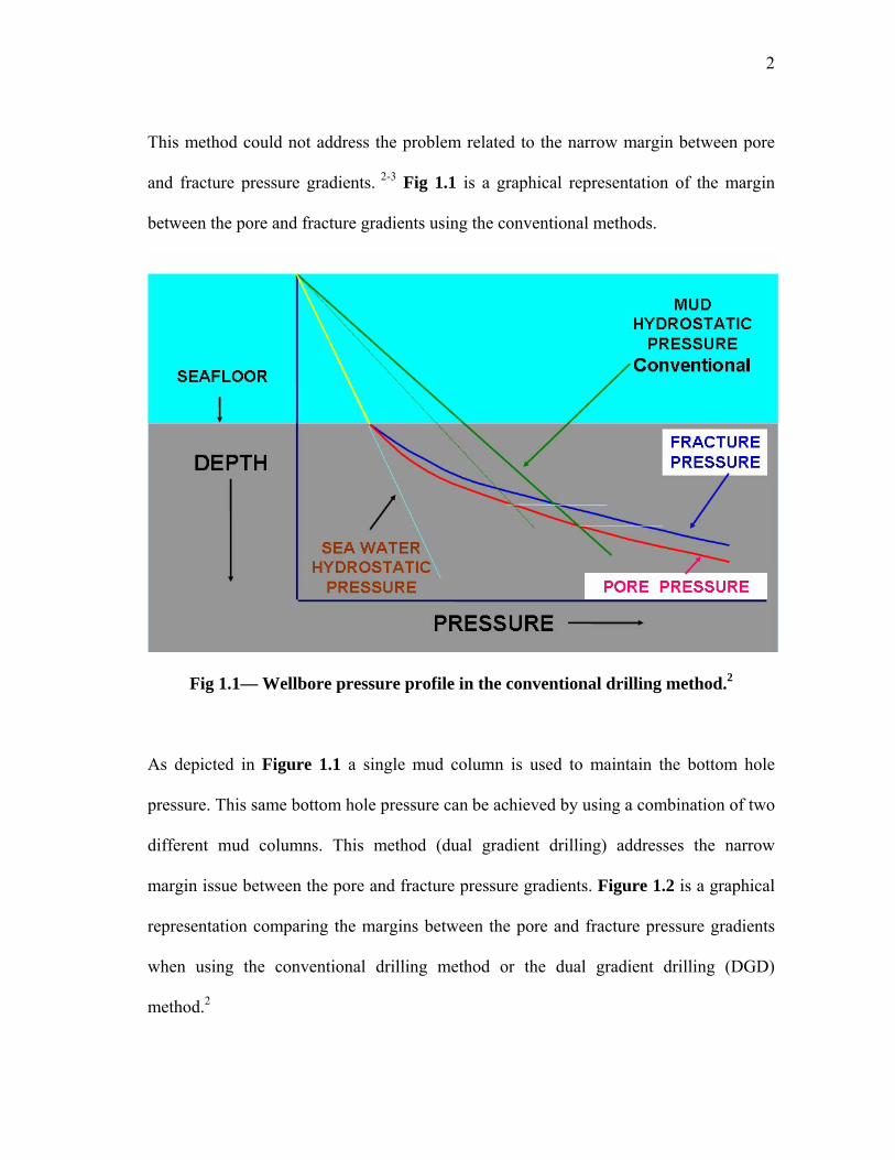
This method could not address the problem related to the narrow margin between pore
and fracture pressure gradients. 2-3 Fig 1.1 is a graphical representation of the margin
between the pore and fracture gradients using the conventional methods.
Fig 1.1— Wellbore pressure profile in the conventional drilling method.2
As depicted in Figure 1.1 a single mud column is used to maintain the bottom hole
pressure. This same bottom hole pressure can be achieved by using a combination of two
different mud columns. This method (dual gradient drilling) addresses the narrow
margin issue between the pore and fracture pressure gradients. Figure 1.2 is a graphical
representation comparing the margins between the pore and fracture pressure gradients
when using the conventional drilling method or the dual gradient drilling (DGD)
method.2

3
Fig 1.2—Wellbore pressure comparison between DGD and conventional drilling methods.2
From the diagram above we can see that the margin between the pore and fracture
pressure gradients was improved when the DGD method was applied. This alone makes
the dual gradient drilling method very attractive.

4
CHAPTER II
LITERATURE REVIEW
The introduction of dual gradient drilling can be dated back to the 1960s. But at that time
the demand for oil and gas was not as high as it is today. The increasing demand has
pushed the oil and gas industry to explore for hydrocarbons in deep waters and this has
led to the development of dual gradient drilling technology. Several methods of
achieving dual gradient have been developed in order to improve deep water drilling.4-6
In this chapter, we are going to discuss the concept of conventional drilling and dual
gradient drilling. In addition we are going to discuss the different methods of achieving
dual gradient, the advantages of the dual gradient method over the conventional method
and finally kick detection and well control in the dual gradient drilling method.
2.1 Conventional Drilling Method
The conventional method involves the use of a marine riser; the marine riser serves as a
link between the drilling rig and the wellhead at the sea floor. It is also used as a guide
for the drill string, a return path for the drilling fluid, and it provides support for the
control cables, choke and kill lines. A single mud density runs from the drilling rig
down to the bottom of the well, maintaining the bottom hole pressure. But, as the water
depth (3000-7500 ft)1 increases the conventional technique often becomes unreliable.
The narrow margin between the pore and fracture pressures in deep waters is one of the
major reliability issues affecting the use of conventional drilling in deep waters.4-5 When

5
using the conventional technique “the exposed sediment of the wellbore sees a pressure
tending to cause formation fracture, this pressure is caused by the full column of mud in
the drilling riser”4. This led to the invention of the dual gradient drilling method.
2.2 Dual Gradient Drilling Method
The dual gradient drilling technique involves the use of two different pressure gradients
in maintaining the bottom hole pressure. The same bottom hole pressure in the
conventional method can be achieved using the dual gradient method. Several methods
have been proposed to achieve dual gradient in the industry today. In one of the methods
the marine riser is filled with a low density fluid (sea water, 8.66 ppg), this helps in
reducing the pressure in the exposed sediments of the wellbore while heavy density fluid
runs from the sea floor to the bottom hole. Figures 2.1 & 2.2 represent a schematic
diagram of the conventional and dual gradient systems and the pressure profiles of
conventional drilling and dual gradient drilling respectively.

6
Fig 2.1— Conventional and dual gradient drilling systems.2
Fig 2.2— Conventional and dual gradient drilling wellbore pressure profiles.

7
In dual gradient drilling all pressure gradients (formation pore and formation fracture
pressure gradients) are referenced to the sea floor and in so doing the margin between
the formation pore and formation fracture pressures is greatly increased. But, in the case
of the conventional drilling method all pressure gradients are referenced to the rig floor.
This can be seen in Figures 2.3 and 2.4 respectively.6 One primary benefit of the wider
margin between the pore and fracture pressures in dual gradient drilling is the
elimination of several casing strings.6 A comparison between casing selection in dual
gradient drilling and conventional drilling can be seen in Figures 2.3 and 2.4
respectively. Lesser number of casing strings allows for deeper target depths, greater
final hole size, and setting larger production tubing strings. It is also important to note
that well kicks and lost circulation would be minimal because of the wide margin
between these pressure gradients. Other benefits of dual gradient drilling include cost
and time savings; which allows drilling in any water depth and has lower weight and
space requirements on the drilling rig.3-6

8
Fig 2.3 — Casing selection in dual gradient drilling.6

9
Fig 2.4— Casing selection in conventional drilling.6
2.3 Methods of Achieving Dual Gradient Drilling
Different methods of achieving dual gradient drilling in deep waters have been proposed
in the industry today. We will briefly discuss these methods.
• Mechanical Lifting (Subsea Mudlift drilling (SMD), Deep Vision and Shell)
• Hollow Glass Spheres
• Mud Dilution (Gas or Liquid)

10
These methods are designed to create two different pressure gradients in the annulus, by
diluting the return mud in the marine riser with a low density fluid or completely
eliminating the marine riser and using a combination return line and subsea pumps6.
2.3.1 Subsea Mudlift Drilling
This method involves the use of a pumping system and return lines. In this case the
marine riser may be eliminated. The pumping system (positive displacement diaphragm
pump) is located at the sea floor and it is designed to send the return mud to the drilling
rig through the return line. The return line has a small diameter of about 6 inches and
runs from the sea floor to the drilling rig.5-6 During drilling operations the drill string and
the annulus are filled with drilling mud while the marine riser is filled with sea water.
Just above the subsea pump inlet a Subsea Rotating Device (SRD) is installed, its
primary function is to provide a mechanical barrier between the return mud in the
annulus and the sea water in the marine riser7. The return mud in the annulus goes
through the return line to the drilling rig. This is made possible by the presence of
positive displacement diaphragm pumps located at the sea floor 7-8. These pumps are
designed to lift drilling fluid and cuttings in the annulus up to the drilling rig through the
return line. In this method the dual gradient concept is achieved by keeping the
hydrostatic pressure in the return line from being transferred to the wellbore3. When the
return mud reaches the drilling rig the separation process is carried out just like in the
conventional drilling method. Deep Vision and Shell’s subsea pumping system utilize
this same concept. Although this method provides flexibility in handling any drilling

11
operation, some disadvantages do exist in this method9. The use of complex subsea
pumps is very costly and it can lead to the introduction of reliability issues. Figure 2.5
represents an illustration of a modified subsea mudlift dual gradient drilling method (no
riser).9
R e tu rnL in e
S u b se a P u m p
R ise r
B O P
Fig 2.5— Schematic diagram of a modified subsea mudlift system.10
2.3.2 Hollow Glass Spheres
The hollow glass spheres method of achieving dual gradient was invented by Maurer
Technology. Hollow-spheres are used as lightweight additive. This additive is pumped
into the riser to reduce the return mud density in the riser9. The design concept of the

12
hollow-spheres, dual gradient system is very similar to the conventional drilling method,
except for the introduction of an injection point at the bottom of the riser.
Here, hollow spheres are mixed in a slurry and pumped into the riser at the sea floor. The
injected slurry at the sea floor reduces the density of the return mud in the riser. Once the
slurry mixture containing mud, cuttings and the hollow-spheres gets to the drilling rig it
is transferred to a separator system. The separator system separates the hollow spheres
from the mud and these spheres are used again in the cycle. Figure 2.6 is a schematic
representation of the hollow-spheres method.9
Some of the advantages of using the hollow-spheres in achieving the dual gradient
concepts are as follows; the hollow spheres are incompressible and they produce a linear
pressure gradient, they can be easily and safely mixed into the drilling mud during
drilling operations and no equipment is required on the sea floor.9 Possible drawbacks of
this method are breakage of the hollow-spheres and difficulties in separating the hollow-
spheres from the drilling mud.9

13
Fig 2.6— Hollow glass-spheres dual gradient drilling system. 9
2.3.3 Riser Dilution (Gas or Liquid)
The riser dilution method is very similar to the hollow-spheres method. Here, gas or
liquid can be used as the lightweight additive. Several authors have studied the use of
gas injection to achieve dual gradient drilling. Clovis A. Lopes and Adam T. Bourgoyne1
presented a paper on the use of an automated gas-lift system for a marine riser that will
maintain the hydrostatic pressure in the subsea well-head equal to the hydrostatic
pressure of the sea water at the sea floor. Abnormal formation pressure can still be

14
maintained in this system by using a weighted mud system that is not gas-cut below the
sea floor1. Herrmann R.P et al11 propose the use of nitrogen injection with a high
pressure concentric casing riser. This will reduce greatly the gas required in the system.
Problems associated with the gas lift method are high compressor costs, the compressors
are large so they occupy space on the drilling rig, difficulties in degassing mud before it
is re-injected into the well, and gas is a compressible fluid, this will lead to nonlinear
pressure gradients.9,11
Not much work has been done on the liquid lift approach. This approach is very similar
to the gas lift method. In this method a low density liquid is injected into the riser at the
sea floor. The low density liquid reduces the density of the return mud in the riser just
like in the gas lift and hollow-sphere methods. When the mixture reaches the rig floor
the liquid is separated into low density liquid and heavy mud.
In this project, we plan to pay more attention to the liquid lift method (riser mud dilution
method). This method of achieving dual gradient drilling is somewhat different from the
others, because it does not utilize subsea pump or a complex pumping system, no
compressors are required (high compressor and nitrogen gas costs are not applicable),
difficulties in degassing mud before it is re-injected into the well are not applicable and
compressibility problems associated with the gas lift method are not applicable.

15
2.4 Description of the Liquid Lift Approach
The liquid lift approach is one of the latest methods of achieving dual gradient in deep
waters. Very little research work has been done on this method. de Boer Luc, 12
described and patented the liquid lift approach (riser dilution) method. As discussed
earlier, this system pumps drilling mud down the drill pipe, through the nozzles in the
drilling bit and then into the open hole where it picks up cuttings. The drilling mud and
cuttings then move up the annulus, into the Blowout Preventer (BOP) stack. The BOP is
a device installed at the sea floor or at the surface used to contain the wellbore and to
prevent a kick from becoming a blowout.12 Just above the BOP stack is a riser charging
line which runs to the drilling rig. The riser charging line introduces a low density fluid
(base fluid 6 ppg) into the riser to mix with the return mud that travels up to the drilling
rig. The base fluid is introduced at the bottom of the riser, so as to achieve a riser density
lesser or equal to sea water density.12 In offshore operations it is well know that the
pressure at the sea floor is equal to sea water hydrostatic pressure.12 Therefore, the
pressure at the beginning of the wellbore is equal to sea water hydrostatic; in order to
maintain the integrity of the wellbore it is important that sea water density is maintained
above the wellbore and heavier density down the wellbore. Therefore, by combining the
appropriate quantities of drilling mud with base fluid the required riser density can be
attained. Equation (2.1) can be used to determine the return mud density in the riser.12

16
( ) ( )( )
i m l swRM
i l
Q QQ Q
ρ ρρ
× + ×=
+ --------------------------------------------- (2.1)
Where;
Qi = flow rate in the annulus (gpm)
Ql = flow rate in the riser charging line (gpm)
ρm = mud density in the annulus (ppg)
ρsw = base density in the charging line (ppg)
ρRM = diluted riser density (ppg)
Figure 2.7 is a schematic representation of the liquid lift, dual gradient drilling method.
Fig 2.7— A typical offshore drilling rig modified for liquid lift drilling.

17
Upon, getting to the drilling rig the return mud passes through the shale shaker and the
cuttings are separated from the return mud. These cuttings are discarded while the return
mud is passed through a separation system (centrifuge device) where the return mud is
separated into wellbore fluid and base fluid. Figure 2.8 is a schematic representation of
the separation system.12
Fig 2.8 — Schematic representation of the separation system.12

18
The liquid lift method is a simplified method of achieving dual gradient drilling. This
system is very similar to the conventional method of drilling. An elaborate pumping
system and large gas compressors are not required in the liquid lift method making this
method more attractive compared to the others. Figure 2.9 represents a schematic
diagram showing the similarities between the liquid lift, dual gradient drilling and the
conventional drilling methods.
Fig 2.9— Schematic diagram of liquid lift and conventional drilling systems.

19
2.5 Advantages of Dual Gradient over Conventional Drilling
Many of the problems associated with deep water drilling when using the conventional
drilling method have been minimized or eliminated through the use of dual gradient
drilling, achieved through return line and subsea pump or marine riser filled with sea
water.
One major advantage of dual gradient drilling over conventional drilling is the wider
margin between the pore and fracture pressure gradients.6 As stated earlier, in deep
waters the pressure gradient between the pore and fracture pressures is narrow. During
drilling operations the pressure at the sea floor is equivalent to sea water density.
Therefore, it is necessary to maintain the required riser density from sea surface to sea
floor. This can be achieved by using the dual gradient concept. Because the increased
margin between the pore and fracture pressure gradients when the dual gradient drilling
concept is applied, the number of casing strings required in deep water drilling is
reduced. The reduction in casing strings brings about several advantages such as reduced
well cost and time savings, improved primary cement capabilities, hole size availability
at deeper depths, and also weight and space requirements for rigs used in deep water
drilling can also be reduced substantially.1-6
The elimination of several casing points has a direct impact on cost and time savings.
The elimination of a casing point saves about 4 to 6 days of rig time, plus the cost of
hole evaluation, casing and logging. If the dual gradient drilling technique is applied

20
successfully the cost of drilling a well will be reduced drastically. The reduced cost will
improve the overall development economics by making more wells economical, it may
facilitate more complex well completions that will increase production and it also allows
for more exploratory wells to be drilled thereby reducing geologic risks.6
From a safety perspective in a dual gradient system with a riser filled with sea water, an
unplanned or emergency disconnect will not result in a sudden underbalance situation in
the wellbore. This is related the presence of the riser margin. But, in conventional
drilling, this leads to a sudden decrease in the hydrostatic pressure imposed on the
wellbore, thereby causing an underbalance situation.6
In the case of well control (influx of formation fluid in the wellbore), in the subsea
mudlift, dual gradient drilling method, an improved managed pressure drilling technique
has been employed in the subsea mudlift dual gradient drilling method.11-13
We can boldly say that dual gradient drilling eliminates or minimizes the problems
associated with conventional drilling, but, there are a lot of uncertainties surrounding the
use of the dual gradient drilling system. There is a shortage in the amount of trained
personnel that can handle these systems, and the introduction of additional equipment
may bring about reliability issues.13

21
2.6 Kick Detection and Well Control in Dual Gradient Drilling
In deep water drilling operations kick detection and well control are two very important
issues that also apply to conventional drilling. A kick occurs when there is an influx of
formation fluid into the wellbore. Keeping the formation fluid out of the wellbore is of
primary importance during most drilling operations. This can be achieved as long as the
mud-column hydrostatic pressure in the drill string plus any annular-friction pressure
exceeds the pore pressure in the wellbore. In spite of this intent formation fluid influx
still occurs, therefore, it is of great importance to quickly detect and control the
formation fluid influx.13-14
There are several methods of detecting possible kicks in dual gradient drilling; these
detection methods could be visual or audible. Some of the common methods of kick
detection are:
• Return rate increase.
• Pit gain.
• Drop in standpipe pressure.
• Drilling Break.
• Increased hook load.
• Increase in rotary torque, drag and fill.
These methods have been successfully utilized in conventional and dual gradient
operations in deep waters. The first three methods listed above are known as primary
kick detection while the others are known as secondary kick detection methods.5

22
After a kick is detected the next step is to stop the further influx of formation fluid in the
wellbore. At this point the major difference between dual gradient drilling and
conventional drilling comes into play. In conventional drilling once a kick is detected the
well is immediately shut in. But, in dual gradient drilling this is not the case, because of
the pressure imbalance. The well cannot be shut-in until equilibrium is reached.
Otherwise it may lead to formation fracture and lost circulation, therefore, the well is
allowed to flow until equilibrium is reached.12-13 This process is known as the u-tubing
effect. The u-tubing effect occurs when the surface pumps are shut down. This causes
the system to equalize the hydrostatic pressure difference between the drill string and the
annulus. Below the mudline the pressures in the drill string and annulus are balanced
while above mudline the height of the mud column inside the drill string is essentially
balanced against sea water inside the riser. Therefore, for equilibrium to occur the mud
level inside the drill string will drop until the hydrostatic head in the drill string above
the mudline is equal to the hydrostatic head of the annulus above the mudline, by
draining the fluid in the drill string through the bit nozzle and up the annulus.1, 3, 4, 13
The u-tubing phenomenon can be prevented by the introduction of a drill string valve
(DSV). A DSV is placed near the bottom of the drill string; it prevents the flow of
drilling mud when the pumps are turned off. The DSV was designed to arrest u-tubing
by sustaining the hydrostatic pressure of the full column of mud in the drill string
whenever the surface pumps are shut down.13

23
When a kick is detected it is very important to take the necessary action so as to prevent
excessive pressure from damaging the casing or fracturing the formation. A well should
be shut-in once a kick is detected. But, in the case of dual gradient drilling without a
DSV the mud in the drill string is allowed to u-tube.13 During that process it is difficult
to stop the further influx of formation fluid into the wellbore. That is why it is very
helpful to use a DSV in dual gradient drilling so that upon detection of a kick the BOP
can be shut-in immediately and the well control procedures can be initiated in a manner
similar to the conventional method.6 When a drillstring valve is not employed a
modified driller’s method proposed by J.J Schubert et al13 can be used. Note that this
method is only used for subsea mudlift, dual gradient drilling systems.1, 5, 6, 13, 14,
1 Slow the subsea pumps to the pre-kick rate (maintain the rig pumps at
constant drilling rate)
2 Allow the drill string pressure to stabilize, and record this pressure and the
circulating rate.
3 Continue circulating at the drill string pressure and rate recorded in step 2
until kick fluids are circulated from the wellbore.
4 The constant drill string pressure is maintained by adjusting the subsea pump
inlet pressure in a manner similar to adjusting the casing pressure with the
adjustable choke on a conventional kill procedure.

24
5 After the kick fluids are circulated from the wellbore, a kill fluid of higher
density is circulated around to increase the hydrostatic pressure (HSP)
imposed on the bottom hole.
In the case of liquid lift dual gradient drilling the choke line circulation method is used.
With this approach, the well is shut in with the blowout preventers (BOPs) and the choke
line valve is opened. The choke line should be kept filled with a fluid having a density
similar or equal to sea water density. The kick is then circulated up the choke line while
base fluid is being injected into the choke line in order to keep the density of the fluid in
the choke line at sea water density. A detailed description of the procedure can be seen
in chapter III.9

25
CHAPTER III
CONCEPTS OF LIQUID LIFT DUAL GRADIENT DRILLING
As discussed in chapter II, liquid lift dual gradient drilling involves the use of a lighter
density fluid known as base fluid to dilute the return mud in the riser. This fluid is
injected at the bottom of the riser. One major function of the drilling fluid in any drilling
operation is its ability to suspend and transport drilling cuttings from bottom hole to the
drilling rig. Therefore, the drilling fluid used in the liquid lift approach must be able to
perform these functions even when a lighter density fluid is mixed with the return mud.
It is important to note that to achieve the required riser density, the right concentration
and injection rate of the base fluid must be determined.
It is very important to note that, for an effective liquid lift dual gradient system,
separation of the return mud to base and wellbore fluids must be possible. For this
system to work efficiently the return mud must be separated into base and wellbore
fluids continuously. De Boer12 provided first hand insights into the use of a centrifuge
separation system.
3.1 Type of Drilling Fluid Used in Dual Gradient Drilling
Drilling fluid is a very important component that should be taken into great
consideration in drilling operations. To ensure success during any drilling operation the
drilling fluid must be able to perform the following functions.15
• Must be able to clean wellbore

26
• Must be able to maintain stable drilling fluid rheological and filtration properties
under varied temperature and pressure conditions
• Possess good barite suspension capabilities
• Stabilize reactive formation
• Well control (hold back formation fluid)
In deep water drilling operations, synthetic-base mud (SBM) is highly recommended as
the fluid of choice for deep water operations. This is due to its superiority in achieving
high penetration rates and maintaining desired wellbore stability. The SBM also have
their drawbacks, in deep waters the temperature can easily reach 400C or 1040F and
below. This in turn can cause the drilling mud to cool down, thereby increasing the
viscosity of the SBM. The increase in viscosity directly affects the equivalent circulation
densities (ECDs) and surge pressures which can lead to lost circulation during drilling
operations. Because a narrow margin exists between the pore pressure and fracture
pressure gradients in deep waters, large fluctuations of the fluid theology are
unacceptable. Therefore, it is very important that the SBM rheology be maintained. 16
When designing a SBM for deepwater drilling the mud properties must be taken into
consideration. These properties have a direct effect on barite suspension, equivalent
circulating density (ECD), effective hole cleaning and most of all, its ability to perform
these functions when the fluid is diluted. Some of the mud properties that should be
taken into consideration are listed below.17

27
• Plastic viscosity can be defined as the slope of the shear stress to shear rate line
above the yield point.18 It measures the resistance of drilling mud to flow as a
liquid.15-16 When the plastic viscosity is low the drilling mud has the ability to
drill fast. But, in the case of high plastic viscosity the ECD will be excessive
which may lead to loss of circulation.
• Yield point has to do with the cuttings carrying ability of the drilling mud. If the
yield point is low the drilling fluid loses its cuttings carrying ability. The yield
point in a drilling mud can be increased by adding a flocculent.17-18
• Mud weight of a drilling fluid is determined based on the wellbore pressures
(pore pressure and fracture pressure).18
• Emulsion stability has to do with how well the water phase is held in the overall
emulsion.18
In the case of the dilution fluid, a density lower than or equal to sea water density is
desirable. It is important to ensure that the dilution fluid has the capability of diluting the
drilling fluid in the riser. Another important aspect to note is the temperature fluctuation
in the wellbore. The dilution fluid must be able to maintain its stability in these
fluctuating conditions. 15, 17

28
3.2 Separation System
The separation system is a very important component in the liquid lift, dual gradient
drilling. The return mud from the riser, which is a combination of drilling fluid and base
fluid, must be separated into useable drilling fluid and dilution fluid. For these fluids to
be useable they must have the right densities and rheological properties.
The separation of the riser fluid into drilling fluid and dilution fluid takes place on a
separation skid located on the drilling rig. This skid consists of a centrifuge device, a set
of return pumps and collection tanks for the separated fluids.12 Firstly; the return mud in
the riser is pumped to the shale shaker. The shale shake is a device designed to separate
most of the cuttings from the return mud, thereby, producing a return mud relatively free
of cuttings. The clean return mud is then pumped into the centrifuge device where the
actual separation takes places. The centrifuge device is composed of a bowl with a
tapered end and helical conveyor which is located inside the bowl. Both components
rotate along a horizontal axis of rotation with the bowl having a faster rotating speed
compared to the helical conveyor.12 Once the clean return mud is fed into the centrifuge
device the return mud is separated into two layers: drilling fluid layer and base fluid
layer. During the process of separation the heavier density fluid is located closer to the
circumference of the tapered bowl while the lower density fluid is located close to the
helical conveyor. The centrifuge device is designed in such a way that the drilling fluid
exits the centrifuge device through the tapered end while the dilution fluid exits through

29
the other end of the bowl. Figure 3.1 is a schematic representation of the centrifuge
device.12
Fig 3.1 – Schematic representation of the centrifuge device.12
3.3 Kick Detection and Well Control
As discussed earlier, kick detection and well control are of great importance in
deepwater drilling operations. The best method of well control is to actually prevent a
kick from occurring but most time kicks do occur during drilling operation. Therefore, a
more practical approach is early detection and control of the kick. Several kick detection
methods have been used successfully in conventional onshore and offshore drilling
operations.1, 14 Some of these methods can be used in dual gradient drilling. The major
difference between the dual gradient drilling and the conventional drilling is the u-tubing
effect. The conventional flow-show (check for flow in the wellbore with pumps off)
which is used as a kick indicator cannot be utilized in dual gradient drilling because of
the u-tubing effect.5, 13 This is caused by the imbalance in hydrostatic pressure between
the drill string and annulus. Once the surface pumps are turned off in a dual gradient

30
system the well will continue to flow until the pressure in the drill string is equal to the
pressure in the annulus. Hence, it is difficult to determine if the well is actually taking a
kick or just u-tubing. But, in the case of the mudlift dual gradient drilling system a more
accurate kick detection method was employed. In this method the subsea mud pumps are
closely monitored. The subsea pumps are usually set at a constant inlet pressure, so
when a kick occurs the annular flow rate increases; this increase is also seen by an
increase in subsea pump rate. This alone can be used as an adequate kick indicator in
mudlift dual gradient drilling.5, 13
In the case of the liquid lift dual gradient drilling, early kick detection presents a
challenge. The above mentioned kick detection method cannot be used, because the
liquid lift system does not utilize a subsea pumps. Therefore, the liquid lift system has to
rely on the conventional methods of kick detection. However, the pressure while drilling
(PWD) tool can be used as a kick indicator in the liquid lift system. PWD tool was
designed for real-time monitoring of the bottom hole pressure (BHP) while drilling. This
tool provides the driller with the BHP, thereby allowing the driller to stay within safety
operating limit.19-21
Once a kick is detected the next step is to stop the further influx and circulate the kick
fluid out of the wellbore. In the mudlift dual gradient system once a kick is detected the
subsea pump is set to the prekick rate while the surface pumps are set at constant
circulation. This leads to an increase in the wellbore pressure generated by the further

31
influx of kick fluid. Once the drill string pressure stabilizes, the drill string pressure and
the pump rate should be recorded while circulating the kick fluid out of the wellbore.
Kill weight mud is then circulated once the kick fluid is out of the wellbore completely.
Figure 3.2 is a graphical representation of kick detection and dynamic shut-in in the
mudlift dual gradient system.1-2
Fig 3.2— Graphic depiction of kick detection and dynamic shut-in for mudlift drilling.1
For the liquid lift dual gradient system, circulating the kick fluid out of the wellbore is
very challenging. Lopes,22 proposed a shut-in procedure for the gas lift, dual gradient
system. This shut-in procedure can be utilized in the liquid lift, dual gradient system. In
this procedure once a kick is detected (PWD or pit gain) the mud pump should be shut

32
down, the well should be closed with the subsea BOP, the liquid injection into the riser
should be shut down and the choke line should be kept in the open position. The choke
line is expected to be filled with sea water.
Because the differential pressures between the drill string and the combined column of
the annulus and choke line, u-tubing phenomenon will take place. This lowers the mud
level in the drill string until equilibrium is reached.
At the end of u-tubing, if the influx of formation fluid into the wellbore continues the
surface choke should be used to introduce a backpressure in the annulus. The amount of
backpressure required to stop the influx of formation fluid can be determined from the
actual BHP obtained from the PWD tool. Once the kick has been contained the kick
fluid is then circulated out of the wellbore through the choke line. After the kick has
been circulated out of the wellbore the kill weight mud is introduced and the liquid
injection rate is adjusted to achieve the required base fluid and drilling fluid mixture that
will maintain the BHP. Figure 3.3 represents a schematic diagram of the process. 20-22
According to Lopes,22 once the u-tubing stops the choke line should be closed and the
BHP should be determined. Lopes,22 proposed the use of a well sounder to determine the
fluid level in the drill string at the end of u-tubing. Once the BHP is known the liquid
injection rate is adjusted to achieve the required mixture density to maintain the BHP.
The kick is then circulated through the choke line.

33
Fig 3.3— Circulating kick through the choke line.2
34
CHAPTER IV
DESCRIPTION OF PROGRAM, EQUATIONS AND RESULTS
Introduction
For a better understanding of the liquid lift, dual gradient drilling a computer program
was developed. This computer program was designed to compute the following;
• Wellbore hydraulics
• Pressure profile (static and dynamic)
• Rate of injection of base fluid into the riser
• U-tubing rate
In this chapter a detailed description of the theoretical concepts, running the program,
data input and output results are provided.

35
4.1 Entering Data and Running the Program
The computer program was developed using the visual basic application in Microsoft
Excel. The computer program starts up like every normal Excel file after the Microsoft
Excel Marco is enabled. After opening the computer program, the input data sheet is
displayed. A picture of the input data sheet can be seen in Figure 4.1. The computer
program contains 5 Microsoft Excel sheets. The first sheet contains the input data which
is displayed at the start of the program. The second contains the output 1 sheet. It
displays the output results for density in riser after injecting the base fluid; the
hydrostatic pressures in drill pipe, annulus and the charging line, also displayed are the
frictional pressure losses in the drill pipe, drilling bit, annulus and charging line. The
third contains the output 2 sheet which displays the output results of the u-tubing rate
(flow rate, time, volume of fluid displaced after u-tubing, fluid level drop in drill string).
This sheet also contains the u-tubing graphs. The last 2 sheets contain the static and
dynamic (circulating) pressure profiles in a dual gradient system respectively.

36
Fig 4.1— Input data sheet.

37
The input data sheet contains five control buttons. These buttons allow the user to run
the program and navigate around the output results. All the necessary input data are
entered in the cells shaded grey.
The data input sheet is kind of divided into four sections. The wellbore geometry input
section allows for one drill collar section, six drill pipe and annular sections and one
riser section. In the drill pipe section the input data for the pipe is entered from bottom to
top while the annulus input data is entered from top to bottom and provision was made
in the computer program for four nozzle input diameters at the drill bit. Two rheometer
readings are displayed on the input data sheet; one represents the drilling fluid while the
other represents the base fluid. The charging line data section contains base fluid density
which ideally should be less than sea water density, injection rate of the base fluid into
the riser, length of the charging line which is usually the water depth and finally, the
inner diameter of the charging line. The general data section contains the sea water
density or the required fluid density in the marine riser, drilling mud density which runs
from top to bottom in the drill string and from bottom to sea floor in the annulus,
circulation rate which is also known as mud flow rate, water depth, total vertical and last
casing depth.
After all the right input data has been entered into the input data sheet, the user is
required to press the execute button on the right side of the input data sheet for the
program to run. Note if a wrong data is entered into the input data sheet an error message
38
would be displayed, informing the user of an input error. This error message is very
precise; it tells the user where the error is located. Once the program is executed
properly the output results and graphs can be viewed using the control buttons on the
right side of the sheet.
4.2 Hydraulics Computation
Hydraulics computation in the liquid lift, dual gradient drilling is somewhat different
from the subsea mudlift and the conventional drilling methods. When compared to the
subsea mudlift method, the pressure jump at the sea floor caused by the subsea pump is
not applicable in the liquid lift method. In the case of the conventional method the dual
mud density is the main difference.5 Figures 4.2, 4.3 & 4.4 are graphical representations
showing the differences in the circulating pressure profiles in the wellbore of the liquid
lift, subsea mudlift and conventional drilling methods.

39
Fig 4.2— Circulating pressure profile for liquid lift dual gradient drilling.2
Fig 4.3— Circulating pressure profile for subsea mudlift drilling.2

40
Fig 4.4 — Circulating pressure profile for conventional riser drilling.2
There are several rheological models that can be used to compute the wellbore
hydraulics (Newtonian model, Bingham model and Power-law model). The API power-
law rheological model was use for this computer program. This model combines the
flow behavior parameters n and k, friction factor and the wellbore geometry to determine
the pressure loss in the system.23-24 Below is a list of the power-law equations used in the
computer program.

41
Power-law equations are listed below. 24
Flow behavior parameters.
n = 3.32 log300
600
RR
4.1
np
Rk
511510 300= 4.2
Mean velocity For the pipe
V )(448.2 2
1dq
= 4.3
For the annulus
V )(448.2 2
12
2 ddq
−= 4.4
Effective viscosity For the pipe
nn
nn
dvke ⎟
⎠⎞
⎜⎝⎛ +
⎟⎟⎠
⎞⎜⎜⎝
⎛=
−
41396100
1
21
µ 4.5
For the annulus
nn
nn
ddvke ⎟
⎠⎞
⎜⎝⎛ +
⎟⎟⎠
⎞⎜⎜⎝
⎛−
=−
312144100
1
12
µ 4.6
To determine turbulence flow or laminar flow we use the Reynolds number For the pipe

42
edvNreµ
ρ928= 4.7
For the annulus
( )e
vddNreµ
ρ12928 −= 4.8
If Nre >2100 the friction factor for both pipe and annulus are
bNreaf = 4.9
where 50
)93.3(log +=
na 4.10
7
)log75.1( nb −= 4.11
If Nre <2100 the friction factor For the pipe
Nref 16= 4.12
For the annulus
Nref 24= 4.13
Frictional pressure gradient For the pipe
dfv
LP
81.25
2ρ=⎟
⎠⎞
⎜⎝⎛∆∆ 4.14
For the annulus

43
)(81.25 12
2
ddfv
LP
−=⎟
⎠⎞
⎜⎝⎛∆∆ ρ 4.15
The above power-law equations are used in the computer program to determine the
pressure losses in the drill pipe, wellbore annulus, the marine riser and in the charging
line. Some minor adjustments where made in the calculation of the pressure drop across
the marine riser. This is caused by the presence of the charging line at the bottom of the
marine riser. When the charging line injects fluid into the marine riser it changes the
flow rate, the mud density and the rheological properties of the mud. In order to account
for these changes the following steps were taken. To obtain the new fluid density and
rheological properties in the marine riser a weighted average of both fluids were taken.
For the flow rate a summation of both flow rates was taken (injection and riser flow
rates). The pressure loss across the drilling bit can be determined by using equation 4.16.
( )223
22
21
2156
nnn dddQPbit++
=ρ 4.16
4.3 Pressure Profile (Static and Circulating)
The pressure profile in the liquid lift, dual gradient drilling differs in so many ways from
the conventional drilling method. When the mud pumps are shut down, the fluid level in
the drill string will drop until the hydrostatic pressure in the drill string above the sea
floor is equal to the hydrostatic pressure related sea water above the sea floor.5 It is

44
important to note that in the process of u-tubing, the base fluid is still being injected into
the marine riser, so as to keep the marine riser density close to sea water density or the
required density in the riser. The maximum mud level drop is a function of mud density,
sea water density and water depth and it can be determined by equation 4.17.5
4.17 ( )max
m sww
m
h Dρ ρ
ρ−
=
where hmax is the maximum mud level drop in the drill string, Dw is the sea water depth,
ρm is the mud density and ρsw is sea water density.5 Also the mud density required to
maintain the bottom hole pressure in the liquid lift, dual gradient drilling can be
determined by using equation 4.18.3
( )0.052
0.052sw w
mw
BHP DD D
ρρ −=
− 4.18
Figure 4.5 is a graphical representation of the static pressure profile from the computer
program. As depicted in the static pressure profile, the fluid level in the drill pipe
dropped to 3120 ft, in order for the hydrostatic pressure in the drill pipe to be in
equilibrium with the annular pressure. Figure 4.6 represents the circulating pressure
profile in the wellbore for liquid lift, dual gradient drilling. As depicted in the graph this
pressure profile differs from the conventional drilling. Note that pressure loss across the
drilling bit occurs only during circulation.5 In order to obtain the pressure profile; we

45
need to determine the standpipe pressure. The standpipe pressure is a function of the
frictional pressure drop in the system, surface pressure and the hydrostatic differences
between the annulus and the drill string. Equation 4.19 is a mathematical representation
of the standpipe pressure.3
( )0.052 w sw m drop surfaceSPP D Pf Pρ ρ= × × − + ∆ + 4.19
where SPP is the standpipe pressure, ∆Pfdrop is the frictional pressure drop in the system
and Psurface is the annulus surface pressure.3, 5 From equation 4.19 we can see that an
increase in frictional pressure drop across the system, which is a function of the
circulation rate, will cause an increase in the standpipe pressure. Figure 4.6 shows a
slight increase in the annulus pressure, this increase reflects the friction pressure in the
annulus during circulation.3 Figure 4.7 is a wellbore representation of the liquid lift, dual
gradient drilling system showing the pressure distribution and pressure losses with a 12.5
ppg mud at the annulus and sea water density in the riser. (wellbore depth = 30,000 ft
and water depth 10,000)

46
Fig 4.5 — Spreadsheet result for the static pressure profile with a maximum mud level drop of 3120 ft with a 12.5 ppg mud.

47
Fig 4.6 — Spreadsheet result for circulation pressure profile with a 12.5 ppg drilling fluid, 7 ppg base fluid, 500 gpm circulation rate and at BHP of 17472 psi.
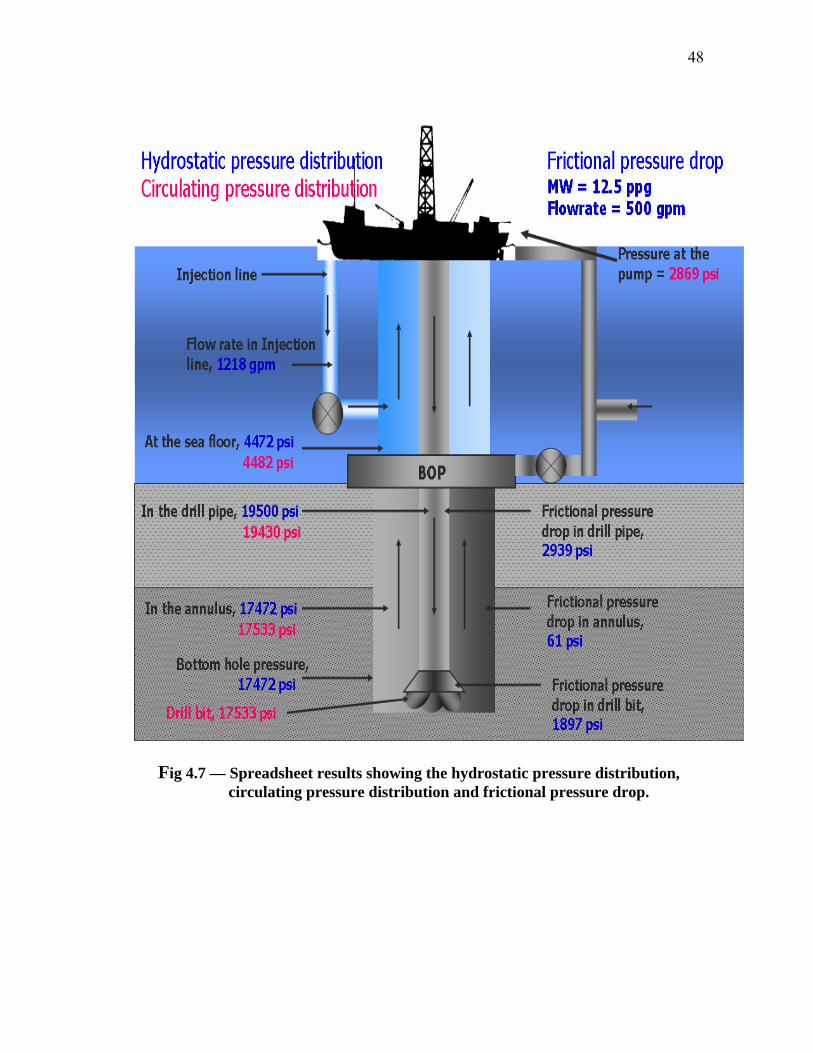
48
Fig 4.7 — Spreadsheet results showing the hydrostatic pressure distribution, circulating pressure distribution and frictional pressure drop.

49
4.4 Injection Rate in the Marine Riser
For this system to work it is very important to keep the marine riser density equal or
slightly higher than sea water density or the required density to maintain the bottom hole
pressure. For the convenience of the user the injection rate required to keep the riser
density at sea water density or required density can be determined. The user can obtain
the injection rate by pressing the button” inject rate”. This action calculates the injection
rate with the input data specified in the charging line section of the input data sheet. The
required injection rate would be displayed in a red cell next to the input injection rate
cell. Injection rate of base fluid into the riser is a very important part of this system; this
can be seen in the graphs below.
Figures 4.8 & 4.9 are graphical representations of mixture density (base density and
drilling fluid density) versus injection rate with a drilling fluid of 12.5 ppg. The graphs
show the mixture densities when the injection rate is varied. From figure 4.8 we can see
that a high flow rate requires a high injection rate to achieve the required density in the
riser. By comparing figures 4.8 and 4.9; we see that a lesser injection rate is required to
dilute the riser when a 6 ppg base fluid is used against a 7 ppg base fluid.

50
Figure 4.8 — Spreadsheet result showing the effect of injection rate (gpm) on the mixture density in the riser (base fluid and drilling fluid) with a 7 ppg base fluid.

51
Figure 4.9 — Spreadsheet result showing the effect of injection rate (gpm) on the mixture density in the riser (base fluid and drilling fluid) with a 6ppg base fluid.
Figures 4.10 & 4.11 are graphical representations of the injection rate required to dilute
the drilling fluid coming into the riser to a specified density (8.66 ppg) at different flow
rate. Figures 4.12 & 4.13 are graphical representations of the effect of injection rate at
the riser on the hydrostatic pressure at the sea floor with a base fluid of 7 ppg and
drilling fluid of 12 ppg. Figure 4.13 is similar to figure 4.12 but a base fluid of 6 ppg is
used.

52
Injection rate vs drilling fluid density
0
1000
2000
3000
4000
5000
6000
8 10 12 14 16 18 20
Drilling fluid density, ppg
Inject
ion ra
te, g
pm
flowrate, 200gpmflowrate, 300gpmflowrate, 400gomflowrate,500gpmflowrate, 600gpmflowrate, 700gpmflowrate, 800gpm
Fig 4.10 — Spreadsheet result showing the injection rate required to dilute the drilling fluid to the desired riser density (8.66 ppg) using a 7 ppg base fluid with a flow rate varied.
Injection rate vs drilling fluid density
0
500
1000
1500
2000
2500
3000
3500
8 10 12 14 16 18 20
Drilling fluid density, ppg
Inject
ion
rate
, gpm
flowrate, 200gpmflowrate, 300gpmflowrate, 400gomflowrate,500gpmflowrate, 600gpmflowrate, 700gpmflowrate, 800gpm
Fig 4.11 —Spreadsheet result showing the injection rate required to dilute the drilling fluid to the desired riser density (8.66 ppg) using a 6 ppg base fluid with a flow rate varied.

53
Injection rate vs hydrostatic pressure on the sea floor
0
500
1000
1500
2000
2500
3400 3900 4400 4900 5400 5900 6400 6900
Hydrostatic pressure on the sea floor, psi
Inje
ctio
n ra
te, g
pm
flowrate, 800gpmflowrate, 700gpmflowrate, 600gpmflowrate, 500gpmflowrate, 400gpmflowrate, 300gpmflowrate, 200gpm
Fig 4.12 — Spreadsheet result showing the effect of injection rate on sea floor hydrostatic with a mixture of 7 ppg base fluid and 12.5 ppg drilling fluid.
Injection rate vs hydrostatic pressure on the sea floor
0
500
1000
1500
2000
2500
3400 3900 4400 4900 5400 5900 6400 6900
Hydrostatic pressure on the sea floor, psi
Inje
ctio
n ra
te, g
pm
flowrate, 800gpmflowrate, 700gpmflowrate, 600gpmflowrate, 500gpmflowrate, 400gpmflowrate, 300gpmflowrate, 200gpm
Fig 4.13 — Spreadsheet result showing the effect of injection rate on sea floor hydrostatic with a mixture of 6 ppg base fluid and 12.5 ppg drilling fluid.

54
4.5 U-tubing Computation
U-tubing is basically a phenomenon that occurs when the mud pumps are shut down in a
dual gradient system. This phenomenon takes place in dual gradient drilling because the
drill string is filled with heavy density mud while the annulus is filled with mud up to the
sea floor and from the sea floor to the surface we have mixture fluid.5 This arrangement
creates a pressure difference between the drill string and the annulus. Once the mud
pumps are shut down the hydrostatic pressure in the drill string drives the fluid column
in the annulus until equilibrium is reached. This driving force works against the
frictional pressure losses in the drill pipe, drill bit, annulus and hydrostatic pressure in
the riser. In order to determine the flow rate at a certain mud level in the drill pipe, the
driving force in the drill pipe is equated to the total frictional pressure drop in the system
by varying the flow rate. This can be achieved by using the bisection numerical
method.3, 5 The driving force equation is represented by equation 4.20, where hx is the
current mud level in the drill pipe.3
( ) ( )( )rmwxwm DhDf ρρ ×−−××= 052.0 4.20

55
CHAPTER V
U-TUBING RATE IN LIQUID LIFT METHOD
5.1 Introduction
As discussed in previous chapters, u-tubing is phenomena that occur when the mud
pumps are shut down. If the mud pumps are shut down the mud column in the drill string
exerts a hydrostatic pressure that is greater than the hydrostatic pressure in the annular
side. Therefore, this causes the mud in the drill pipe to free fall until it reaches
equilibrium. According to Choe,5 during u-tubing the annular pressure should be kept
from increasing in order to prevent formation fracture. In subsea mudlift drilling, the
right annular pressure can be maintained by varying the inlet pressure in the subsea
pump. But, in liquid lift, dual gradient drilling a different approach is utilized to maintain
the annular pressure. U-tubing is phenomena that occur in all methods of achieving dual
gradient and the rate at which it occurs are very similar. Figure 5.1 is a plot from the
subsea mudlift drilling simulator of u-tubing rate against time in the drill string when the
pumps are shut down (u-tubing rate dual gradient drilling). From the graph we can notice
changes in the u-tubing rate pattern. According to Choe, 5 this pattern was described as
follows; the initial circulation rate (1), when the pumps are shut down, we see a dynamic
effect as the fluid level drops (2), drop in fluid level decreases the driving force of the
mud column in the drill string (3), change from turbulent flow to laminar flow is noticed
(4) and finally the fluid comes to a stop (5). 2, 5 But, dual gradient drilling systems,
incorporated with DSV do not experience the u-tubing phenomena because the DSV in
the drill pipe prevents the drilling mud from free falling.3, 26

56
According to Johansen,26 there are several parameters that affect the rate of u-tubing in
dual gradient drilling. Mud weight, initial circulation rate, drill pipe diameter, bit nozzle
size, wellbore depth and fluid viscosity are the parameters that affect u-tubing rate.
Fig 5.1— U-tubing rate (gpm) vs. time (min).26

57
5.2 U-Tubing in the Liquid Lift, Dual Gradient Drilling Method
In liquid lift dual gradient drilling, when u-tubing occurs, it is important that the density
in the riser stays within the required sea water density in order to provide the right
annular pressure needed to keep the formation fluid from entering the wellbore.
Therefore, the injection of base fluid into the riser should be continued during u-tubing.
If the injection of base fluid is shut down during u-tubing the mud inside the drill string
will displace the light density liquid in the marine riser and replace it with the heavy
mud. This will cause an increase in the hydrostatic pressure in the annular side which in
turn can fracture the formation. Figure 5.2 is a graphical representation of the pressure
profile during u-tubing, without base fluid injection.
Fig 5.2 – U-tubing with riser injection shut-down.

58
But, the greatest issue is the determination of the injection rate of the base fluid during u-
tubing in order to maintain the right annular pressure. This is related to the fact that as
the mud level in the drill string drops there is a dynamic change in u-tubing rate. One
possible way of handling this issue is to monitor the u-tubing rate. For example the
current computer model can determine the injection rate required as the u-tubing rate
changes. Figure 5.3 shows the required injection rate at anytime during u-tubing. This
graph is very similar to the graph of flowrate versus time during u-tubing shown in
Figure 5.4.
Injection rate during u-tubing
0
200
400
600
800
1000
1200
1400
0 5 10 15 20 25
Time, min
Inje
ctio
n ra
te, g
pm
Fig 5.3 — Spreadsheet result showing the required injection rate at anytime during u-tubing with a base fluid of 7ppg, drilling fluid of 12.5 ppg and flowrate of 500 gpm

59
U-tubing Rate
0
100
200
300
400
500
600
0 5 10 15 20 25
Time (min)
Flow
rate
(gpm
)
Fig 5.4 — Spreadsheet result showing the u-tubing rate with a base fluid of 7 ppg, drilling fluid of 12.5 ppg and an initial flowrate of 500 gpm.
Figure 5.5 is a graphical representation of injection rate versus flow rate as u-tubing
takes place. The result obtained from these graphs can be used to monitor and determine
the injection rate required during u-tubing. Therefore, in order to maintain the balance
between the flow rate and injection rate during u-tubing, a device is required to monitor
the change in u-tubing rate in the drill string and implement the new injection rate
needed to dilute the marine riser. This problem is particular to the riser dilution method.
In the case of riserless drilling, the pressure exerted by the sea water column, is replaced
with the inlet pressure of the subsea pumps. This makes it easier to maintain the bottom
hole pressure during u-tubing in subsea mudlift drilling. In the case of detecting a kick

60
during u-tubing the PWD tool is a very good device to use. According to Ostermeier,19
the PWD tool was designed to detect and provide an estimate of sand pore pressure
when in overpressured sand.
U-tubing rate
0
100
200
300
400
500
600
0 500 1000 1500 2000 2500 3000 3500
injection rate, gpm
flow
rate
, gpm
12 ppg13 ppg14 ppg15 ppg16 ppg17 ppg18 ppg
Fig 5.5 — Spreadsheet result showing injection rate versus flow rate during u- tubing with a 12.5 ppg drilling fluid and a 7 ppg base fluid.

61
CHAPTER VI
CONCLUSIONS AND RECOMMENDATION
6.1 Conclusion
The liquid lift method is a dual gradient drilling technique that does not utilize elaborate
subsea pumps, a large gas compressor or hollow spheres that will introduce
complications into the system. This makes it a more attractive system compared to the
other methods of dual gradient drilling. Though, there are advantages and disadvantages
to this method but the advantages outweigh the disadvantages.
In conclusion,
• At the riser, the fluid mixture of base fluid and drilling fluid must still have the
suspension and transporting capacities.
• It is really important that the sea water density in the riser is maintained, so as not
to cause formation fracture. Therefore, no matter the operation being carried out,
as long as circulation is taking place in the wellbore, base fluid should always be
injected into the riser to keep the riser fluid density at sea water density. During
u-tubing, the injection rate of the base fluid must correspond to the u-tubing rate
in order to maintain that balance in the riser.
• Well control, one of the biggest problems facing the drilling industry must be
taken care of for this system to work effectively. In the liquid lift, dual gradient
drilling a kick can be detected by using one of the conventional techniques (pit
gain, increased hook load, drilling break) or the use of a PWD tool. The well

62
control procedure for the gas lift system can be applied in the liquid lift method.
If a kick is detected the subsea BOP should be closed, mud pump shut down and
the choke line should be kept in the open position filled with sea water. U-tubing
should be allowed in the wellbore and then circulate up the choke line. The choke
line should also be diluted with the base fluid in order to keep the fluid in the
choke line at sea water density and maintain the bottom hole pressure.
6.2 Recommendation
One major issue facing this system is the u-tubing effect. The introduction of a drill
string valve DSV will make this method a more reliable and cost effective method of
achieving dual gradient drilling in deep waters.
Another concern is the difficulty in maintaining the right BHP, especially during well
control operations. A PWD tool should be used to overcome this potential problem.
63
NOMENCLATURE
BHP = bottom hole pressure, psi
BOP = blowout preventer
d1 = inner diameter of drill pipe, in
d1 = annulus inner diameter, in
d2 = annulus outer diameter, in
dnz = nozzles diameter, (1/32) in
D = total depth, ft
DGD = dual gradient drilling
DSV = drill string valve
Dw = water depth, ft
ECD = equivalent circulation density
f = frictional factor
F = frictional driving force during u-tubing rate, psi
gpm = gallons per minute
HSP = hydrostatic pressure, psi
hmax = maximum mud level drop inside drill string, ft
hx = mud level drop inside the drill string at a certain time, ft
in = inches
ID = inner diameter, in
k = power-law consistency index
MWD = measurement while drilling

64
n = power-law fluid behavior
Nre = Reynolds number
OD = outer diameter, in
Pbit = bit pressure loss, psi
ppg = pounds per gallon
Psurface = pressure at the surface, psi
psi = pounds per square inches
PWD = pressure while drilling
q = fluid flowrate, gpm
Qi = flowrate in the annulus, gpm
Ql = flowrate in the riser charging line, gpm
R600 = viscometer reading at 600 rpm
R300 = viscometer reading at 300 rpm
R100 = viscometer reading at 100 rpm
R3 = viscometer reading at 3 rpm
SBM = synthetic base mud
SMD = subsea mudlift drilling
SRD = subsea rotating device
SPP = stand pipe pressure
v = fluid velocity
ρm = drilling fluid density, ppg
ρsw = base density in the riser charging line, ppg

65
ρrm = diluted riser density, ppg
µe = effective fluid viscosity
∆P/ ∆L = frictional pressure loss per unit length
∆Pfdrop = frictional pressure loss in the entire system
∆Ppump = pump pressure
66
REFERENCES
1. Schubert, J.J.: “Well Control Procedures for Riserless Mudlift Drilling, and Their
Integration into a Well Control Training Program,” Ph.D. Dissertation, Texas
A&M University, College Station, Texas. (1999)
2. Juvkam-Wold H.C.: “Dual Gradient Drilling Lecture Note,” Texas A&M
University, College Station, Texas (2007).
3. Vera, L.V. “Potential Use of Hollow Sphere in Dual Gradient Drilling”, M.S.
Thesis, Texas A&M University, College Station, Texas. (2002)
4. Lopes, C.A., Bourgoyne, T Jr., .: “The Dual Density Riser Solution,” paper SPE
37628 presented at the 1997 SPE/IADC Drilling Conference, Amsterdam, The
Netherlands 4-6 March 1997
5. Choe. J., .: “Analysis of Riserless Drilling and Well-Control Hydraulic,” paper
SPEDC 14 (1): 71-81 SPE 55056-PA. DOI.
http://www.spe.org/elibrary/servlet/spepreview?id-55056-PA.
6. Elieff, B.A. “Top Hole Drilling with Dual Gradient Technology to Control
Shallow Hazards,” M.S. Thesis, Texas A&M University, College Station, Texas
(2006).
7. Smith, K.L, Gault, A.D., Witt, D.E., and Weddle, C.E..: “Subsea Mudlift Drilling
Joint Industry Project: Delivering Dual Gradient Drilling,” paper SPE 71357
presented at the 2001 SPE Annual Technical Conference and Exhibition held in
New Orleans, Louisiana, 30 September – 3 October 2001.

67
8. Eggemeyer, J.C., Akins, M.E., Brainard, P.E., Judge, R.A., Peterman, C.P.,
Scavone, L.J., Thethi, K. S.: ”SubSea MudLift Drilling: Design and
Implementation of a Dual Gradient Drilling System,” paper SPE 71359 presented
at the 2001 SPE Annual Technical Conference and Exhibition, New Orleans,
Louisiana, September 30 – October 3, 2001.
9. Cohen, J.H., and Deskins, G., SPE,.: “Use of Lightweight Solid Additive to
Reduce the Weight of Drilling Fluid in the Riser,” paper SPE/IADC 99174
prepared for presentation at the IADC/SPE Drilling Conference, Miami, Florida,
21-23 February 2006.
10. Esobar, A.: “A Simulation Study of a Subsea Mudlift Drilling System During
Tripping Operation,” M.S., Thesis Texas A&M University, College Station,
Texas (1999).
11. Herrmann, R.P. and Shaughnessy, J.M.: “Two Methods for Achieving a Dual
Gradient in Deepwater,” paper SPE/IADC 67745 presented at the SPE/IADC
Drilling Conference, Amsterdam, The Netherlands, February 27 – March 1,
2001.
12. de Boer, L.: “System and Method for Treating Drilling Mud in Oil and Gas Well
Drilling Applications,” United States Patent Application 20030217866,
November 27, 2003-c.
13. Schubert, J.J., Juvkam-Wold, H.C. and Choe, J.: “Well-Control Procedures for
Dual-Gradient Drilling as Compared to Conventional Riser Drilling,” paper SPE
99029, http://www.spe.org/elibrary.

68
14. David. W., Brittenham, T. and Moore, P.L.: Advanced Well Control,
Monograph Series, (2003), 10. 134-184
15. Carlson, T., and Hemphill, T.: “Meeting the Challenges of Deepwater Gulf of
Mexico Drilling with Non-Petroleum Ester- Based Drilling Fluids,” paper SPE
28739 presented at the International Petroleum Conference & Exhibition of
Mexico, Veracruz, Mexico, 10-13 October 1994
16. van Oort, E., Lee, J., Freidheim, J. and TOUPS, B.: “New Flat-Rheology
Synthetic-Based Mud for Improved Deepwater Drilling,” paper SPE 90987
presented at the SPE Annual Technical Conference and Exhibition, Houston,
Texas, 26-29 September 2004
17. Shelton, J. “Experimental Investigation of Drilling Fluid Formulations and
Processing Methods for a Riser Dilution Approach to Dual Density Drilling,”
M.S Thesis, Louisiana State University, Baton Rouge (2005)
18. Schlumberger Oil Field Glossary.: http://www.slb.com (2007)
19. Ostermeier, R.M., Pelletier, J.H., Winker, C.D., Nicholson, J.W., Rambow, F.H.
and Cowan, K.M.: “Dealing with Shallow-Water in the Deepwater Gulf of
Mexico,” paper OTC 11972 presented at the 2000 Offshore Technology
Conference, Houston, Texas, 1-4 May 2004.
20. Hariharan, P.R. and Judge, B.: “ECD Management Tool Offers Potential for
Reducing Drilling Problems and Costs,” paper OTC 16623 presented at the
Offshore Technology Conference, Houston, Texas, 3-6 May 2004.

69
21. Perez-Tellez, C., Urbieta-Lopez, A., Miller, A., and Banda-Morato, R.G.:
“Bottom Hole Pressure Measurements: Indispensable Tool for Optimizing
Underbalanced Drilling Operations,” paper presented at the 2003 Offshore
Technology Conference, Houston, Texas, 5-8 May 2003.
22. Lopes, C., “Feasibility Study on the Reduction of Hydrostatic Pressure in a Deep
Water Riser Using a Gas-Lift Method,” Ph.D Dissertation, Louisiana State
University, Baton Rouge (1997).
23. Ayeni, K.: “Drilling Fluid Hydraulic Simulator with Emphasis on Rheological
Model,” M.Sc. Thesis, University of Oklahoma, Norman (2004)
24. Bourgoyne, A.T. Jr., Chenevert, M.E., Millheim, K.K., and Young, F.S. Jr.:
“Applied Drilling Engineering,” Monograph Series, SPE, Richardson, TX (1991)
2. 42-75, 113-173
25. Schubert, J.: “Advanced Well Control Lecture Note,” Texas A&M University,
College Station, Texas (2005).
26. Johansen, T.: “Subsea Mudlift Drilling – Evaluation of the Pressure Differential
Problem with Subsea,” M.S. Thesis, Texas A&M University, College Station,
Texas (2000)

70
APPENDIX A
Spreadsheet result showing the injection rate required to dilute different drilling fluid
densities in the riser to the desired riser density (8.6 ppg) at a varied circulation rate. For
example in fig A-1 if a 10 ppg drilling fluid is used and circulated at 800 gpm, an
injection rate of approximately 1900 gpm is required to dilute the riser to 8.6 ppg.
Injection rate vs drilling fluid density
0
2000
4000
6000
8000
10000
12000
14000
16000
8 10 12 14 16 18 20
Drilling fluid density, ppg
Inje
ctio
n ra
te, g
pm
flowrate, 200gpmflowrate, 300gpmflowrate, 400gomflowrate,500gpmflowrate, 600gpmflowrate, 700gpmflowrate, 800gpm
Fig A-1. —Spreadsheet result showing the injection rate required to dilute the drilling fluid to the desired riser density (8.66 ppg) using a 8 ppg base fluid.

71
Injection rate vs drilling fluid density
0
1000
2000
3000
4000
5000
6000
8 10 12 14 16 18 20
Drilling fluid density, ppg
Inject
ion
rate
, gpm
flowrate, 200gpmflowrate, 300gpmflowrate, 400gomflowrate,500gpmflowrate, 600gpmflowrate, 700gpmflowrate, 800gpm
Fig A-2. —Spreadsheet result showing the injection rate required to dilute the drilling fluid to the desired riser density (8.66 ppg) using a 7 ppg base fluid.
Injection rate vs drilling fluid density
0
500
1000
1500
2000
2500
3000
3500
8 10 12 14 16 18 20
Drilling fluid density, ppg
Inject
ion
rate
, gpm
flowrate, 200gpmflowrate, 300gpmflowrate, 400gomflowrate,500gpmflowrate, 600gpmflowrate, 700gpmflowrate, 800gpm
Fig A-3. —Spreadsheet result showing the injection rate required to dilute the drilling fluid to the desired riser density (8.66 ppg) using a 6 ppg base fluid.

72
The graphs below show the effect of injection rate in mixing the base fluid and the
drilling fluid. As depicted in fig A-4, an increase in injection rate with a low circulation
rate further decreases the mixture density in the marine riser. For example an injection
rate of 1600 gpm with circulation rate of 500 gpm, results to a lower mixture density
(drilling fluid and base fluid) to 8.36 ppg.
Figure A-4 — Spreadsheet result showing the effect of injection rate (gpm) on the mixture density in the riser (base fluid and drilling fluid) with a 7 ppg base fluid and 12 ppg drilling fluid.

73
Figure A-5 — Spreadsheet result showing the effect of injection rate (gpm) on the mixture density in the riser (base fluid and drilling fluid) with a 6 ppg base fluid and 12 ppg drilling fluid.
Figure A-6 — Spreadsheet result showing the effect of injection rate (gpm) on the mixture density in the riser (base fluid and drilling fluid) with a 7 ppg base fluid and 13 ppg drilling fluid.

74
Figure A-7— Spreadsheet result showing the effect of injection rate (gpm) on the mixture density in the riser (base fluid and drilling fluid) with a 6 ppg base fluid and 13 ppg drilling fluid.
Figure A-8— Spreadsheet result showing the effect of injection rate (gpm) on the mixture density in the riser (base fluid and drilling fluid) with a 6 ppg base fluid and 14 ppg drilling fluid.
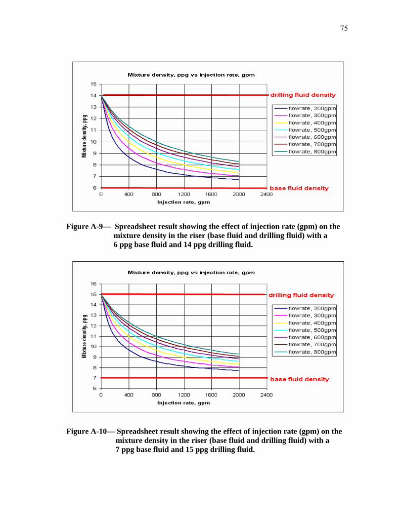
75
Figure A-9— Spreadsheet result showing the effect of injection rate (gpm) on the mixture density in the riser (base fluid and drilling fluid) with a 6 ppg base fluid and 14 ppg drilling fluid.
Figure A-10— Spreadsheet result showing the effect of injection rate (gpm) on the mixture density in the riser (base fluid and drilling fluid) with a 7 ppg base fluid and 15 ppg drilling fluid.

76
Figure A-11— Spreadsheet result showing the effect of injection rate (gpm) on the mixture density in the riser (base fluid and drilling fluid) with a 6 ppg base fluid and 15 ppg drilling fluid.

77
The graphs below show the effect of injection rate in mixing the base fluid and the
drilling fluid. The base fluid injected into the riser is greater than or slightly less than sea
water density. It is important to note that sea water density is not required at all times.
But, it is of utmost importance that the composite column of fluid in the annulus and the
riser stay within the pore and fracture pressures of the wellbore. The graph below
represents mixture density versus injection rate when base fluid is greater than sea water
density.
Figure A-12— Spreadsheet result showing the effect of injection rate (gpm) on the mixture density in the riser (base fluid and drilling fluid) with a 9 ppg base fluid and 12.5 ppg drilling fluid.

78
Figure A-13— Spreadsheet result showing the effect of injection rate (gpm) on the mixture density in the riser (base fluid and drilling fluid) with a 9 ppg base fluid and 13 ppg drilling fluid.
Figure A-14— Spreadsheet result showing the effect of injection rate (gpm) on the mixture density in the riser (base fluid and drilling fluid) with a 9 ppg base fluid and 14 ppg drilling fluid.

79
Figure A-15— Spreadsheet result showing the effect of injection rate (gpm) on the mixture density in the riser (base fluid and drilling fluid) with an 8.5 ppg base fluid and 14 ppg drilling fluid.
Figure A-16— Spreadsheet result showing the effect of injection rate (gpm) on the mixture density in the riser (base fluid and drilling fluid) with an 8.5 ppg base fluid and 13 ppg drilling fluid.

80
Figure A-17— Spreadsheet result showing the effect of injection rate (gpm) on the mixture density in the riser (base fluid and drilling fluid) with an 8.5 ppg base fluid and 13 ppg drilling fluid.

81
The graphs below show a comparison between u-tubing rate and the required injection
rate at any time during u-tubing. From these results, the injection rate at anytime during
u-tubing can be determined.
U-tubing rate
0
200
400
600
800
1000
1200
0 5 10 15 20 25
Time , min
Gallon pe
r minute
Injection rate, gpmFlow rate, gpm
Figure A-18— Spreadsheet result showing u-tubing rate and the corresponding injection rate required to maintain the riser density with a 12 ppg drilling fluid, 7 ppg base fluid and drill pipe diameter 4.276 in.
U-tubing rate
0
200
400
600
800
1000
1200
1400
1600
0 5 10 15 20 25
Time , min
Gallo
n pe
r m
inut
e
Injection rate, gpmFlow rate, gpm
Figure A-19— Spreadsheet result showing u-tubing rate and the corresponding injection rate required to maintain the riser density with a 13 ppg drilling fluid, 7 ppg base fluid and drill pipe diameter 4.276 in.

82
U-tubing rate
0
200
400
600
800
1000
1200
1400
1600
0 5 10 15 20 25
Time, min
Gal
lon
per m
inut
eInjection rate,gpm 13ppg
Flow rate, gpm13ppg
injectionrate,gpm 12ppg
Flow rate, gpm12ppg
Figure A-20— Spreadsheet result showing u-tubing rate and the corresponding injection rate required to maintain the riser density with a 7 ppg base fluid and drill pipe diameter 4.276 in.
U-tubing rate
0
200
400
600
800
1000
1200
1400
1600
0 5 10 15 20 25 30 35
Time, min
Gal
lon
per m
inut
e
Injection, gpm12ppg
Flow rate, gpm12ppg
Injection, gpm13ppg
Flow rate, gpm13ppg
Figure A-21— Spreadsheet result showing u-tubing rate and the corresponding injection rate required to maintain the riser density with a 7 ppg base fluid and drill pipe diameter 3 in.

83
Spreadsheet result showing u-tubing rate with corresponding injection rate at any time
during u-tubing with varying parameters that affect u-tubing as such, base fluid density,
drilling fluid density and drill pipe diameter.
U-tubing rate
0
100
200
300
400
500
600
700
800
900
0 5 10 15 20 25
Time, min
Gal
lon
per m
inut
e
Injection rate,gpm 13ppg
Flow rate, gpm13ppg
injectionrate,gpm 12ppg
Flow rate, gpm12ppg
Figure A-22— Spreadsheet result showing u-tubing rate and the corresponding injection rate required to maintain the riser density with a 6 ppg base fluid and drill pipe diameter 4.276in.

84
U-tubing rate
0
100
200
300
400
500
600
700
800
900
0 5 10 15 20 25 30 35
Time, min
Gal
lon
per m
inut
e
Injection, gpm12ppg
Flow rate, gpm12ppg
Injection, gpm13ppg
Flow rate, gpm13ppg
Figure A-23— Spreadsheet result showing u-tubing rate and the corresponding injection rate required to maintain the riser density with a 6 ppg base fluid and drill pipe diameter 3in.

85
VITA
NAME: Ugochukwu Nnamdi Okafor
PERMANENT ADDRESS: 169 Crownpoint Drive
Hyde Park, MA 02136
EDUCATION: B.S. in Electrical Engineering
University of Lagos
Lagos, Nigeria 2004
M.S. in Petroleum Engineering
Texas A&M University, 2007