evaluation of injection materials for the repair of deep
TRANSCRIPT

Technical Report REMR-CS-48 August 1995
US Ärmy Corps of Engineers Waterways Experiment Station
Repair, Evaluation, Maintenance, and Rehabilitation Research Program
Evaluation of injection materials for the Repair of Deep Cracks in Concrete Structures
by Paul D. Krauss, John M. Scanlon, Margaret A. Hanson, Wiss, Janney, Elstner Associates, Inc.
Approved For Public Release; Distribution Is Unlimited
19951214104 Prepared for Headquarters, U.S. Army Corps of engineers
THIS DOCUMENT IS BEST
QUALITY AVAILABLE. THE
COPY FURNISHED TO DTIC
CONTAINED A SIGNIFICANT
NUMBER OF PAGES WHICH DO
NOT REPRODUCE LEGIBLY.

Repair, Evaluation, Maintenance, and Rehabilitation Research Program
Technical Report REMR-CS-48 August 1995
Evaluation of Injection Materials for the Repair of Deep Cracks in Concrete Structures by Paul D. Krauss, John M. Scanlon, Margaret A. Hanson
Wiss, Janney, Elstner Associates, Inc. 330 Pfingston Road Northbrook, IL 60062-2095 Accesion For
NT!S ' CRA&! DTiC TA3 Unannounced Justification
By Distribution |
D D
Dist
rV
Avail and/or Special
Final report Approved for public release; distribution is unlimited
R"> WAlL'ijL mBmi
&
Prepared for U.S. Army Corps of Engineers Washington, DC 20314-1000
Under Contract No. DACW39-93-C-0115 Work Unit 32636
Monitored by U.S. Army Engineer Waterways Experiment Station 3909 Halls Ferry Road, Vicksburg, MS 39180-6199

US Army Corps of Engineers Waterways Experiment Station
BMXMHBnAL LABORATORY
PORWOflMATION CONTACT;
PUBLIC AFFAIRS OFFICE U.S. ARMY ENGINEER WATERWAYS EXPERMENT STATION 3909 HALLS FERRY ROAD VICKSBURQ, MISSISSIPPI 391904199 PHONE: (601)634-2902
AREA OF RESERVATON - ZT «q fa»
Waterways Experiment Station Cataloging-in-Publication Data
Krauss, P. D. (Paul D.) Evaluation of injection materials for the repair of deep cracks in
concrete structures / by Paul D. Krauss, John M. Scanlon, Margaret A. Hanson ; prepared for U.S. Army Corps of Engineers ; monitored by U.S. Army Engineer Waterways Experiment Station.
102 p.: ill.; 28 cm. — (Technical report; REMR-CS-48) Includes bibliographic references. 1. Concrete — Cracking — Maintenance and repair. 2. Concrete
construction —Maintenance and repair. 3. Epoxy resins. I. Scanlon, John M. II. Hanson, Margaret A. III. United States. Army. Corps of Engineers. IV. U.S. Army Engineer Waterways Experiment Station. V. Repair, Evaluation, Maintenance, and Rehabilitation Research Program. VI. Title. VII. Series: Technical report (U.S. Army Engineer Waterways Experiment Station); REMR-CS-48. TA7 W34 no.REMR-CS-48

Contents
Preface vi
Conversion Factors, Non-SI to SI Units of Measurements vii
1—Introduction 1
Background . , 1 Objective 1 Scope 2
2—Survey of Existing Information 4
Literature Review 4 Industry Survey 7 Material Selection 8
3—Test Program 9
General 9 Viscosity 9 Gel Time 12 Penetration 13 Surface Tension 14 Interfacial Tension 16 Bond Strength 17
4—Summary and Discussion of Results 22
References 26
Appendix A: Annotated Bibliography and Related Articles Al
Appendix B: Manufacturer's Data Bl
Appendix C: Raw Data From Testing Cl
Appendix D: Draft Bond Test Procedure Dl
Appendix E: Photographs of Bond Strength Test Specimens El
SF298
in

List of Figures
Figure 1.
Figure 2.
Figure 3.
Figure 4.
Figure 5.
Figure 6.
Figure Dl.
Figure D2.
Figure El.
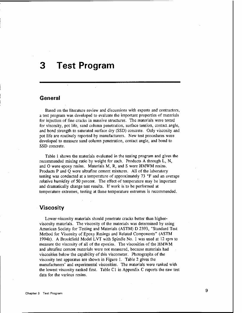
Viscosity test apparatus 11
Sand column penetration test 14
Surface tensiomat for surface tension measurements .... 16
Fabrication of SSD bond beam samples 18
Bond beam sample and resin drops shown on glass slides for contact angle measurement 19
Overall view of bond beam samples after flooding of cracks 19
Apparatus for bonding strength test in center point loading D5
Plan of apparatus for bond test concrete overlay and patching materials D6
Photographs of bond strength test samples after fracture E2
List of Tables
Table 1.
Table 2.
Table 3.
Table 4.
Table 5.
Table 6.
Table 7.
Table 8.
Table Bl
Table B2
Table Cl
Material Identification and Mixing by Weight 10
Summary of Viscosity Test Results 12
Summary of Gel Time Test Results 13
Summary of Depth of Penetration Test Results 15
Summary of Surface Tension and Contact Angle Test Results 17
Summary of SSD Bond Strength Test Results 20
Summary of Material Test Results 23
Summary of Experimental Rankings 24
Manufacturer's Product Data for Epoxy Resins B2
Typical Manufacturer's Product Data B3
Raw Data for Viscosity of Resins C2
IV

Table C2. Raw Data for Material Penetration Depth in Coarse Sand Column C3
Table C3. Raw Data for Material Penetration Depth in Fine Sand Column C4
Table C4. Raw Data for Surface Tension Tests C5
Table C5. Raw Data for Contact Angle Tests C6
Table C6. Raw Data for Beam Bond Tests C7

Preface
The study reported herein was authorized by Headquarters, U.S. Army Corps of Engineers (HQUSACE), under Civil Works Research Work Unit 32636, "New Concepts in Maintenance and Repair of Concrete Structures," for which Mr. James E. McDonald, Structures Laboratory (SL), U.S. Army Engineer Waterways Experiment Station (WES), is the Principal Investigator. This work unit is part of the Concrete and Steel Structures Problem Area of the Repair, Evaluation, Maintenance, and Rehabilitation (REMR) Research Program sponsored by HQUSACE, for which Mr. McDonald is the Problem Area Leader.
The REMR Technical Monitor is Dr. Tony C. Liu, HQUSACE. Mr. William N. Rushing (CERD-C) is the REMR Coordinator at the Directorate of Research and Development, HQUSACE. Mr. James E. Crews (CECW-O) and Dr. Liu (CECW-EG) serve as the REMR Overview Committee. Mr. William F. McCleese, WES, is the REMR Program Manager.
The study was performed by Wiss, Janney, Elstner Associates, Inc. (WJE), under contract to WES. Mr. John M. Scanlon, WJE, was the Project Manager. The work was conducted under the general supervision at WES of Mr. Bryant Mather, Director, SL, and Mr. McCleese, Acting Chief, Concrete Technology Division, and under the direct supervision of Mr. McDonald. This report was prepared at WJE by Messrs. Paul D. Krauss and John M. Scanlon and Ms. Margaret A. Hanson.
At the time of publication of this report, Director of WES was Dr. Robert W. Whalin. Commander was COL Bruce K. Howard, EN.
The contents of this report are not to be used for advertising, publication, or promotional purposes. Citation of trade names does not constitute an official endorsement or approval of the use of such commercial products.
VI

Conversion Factors, Non-SI to SI Units of Measurement
Non-SI units of measurement used in this report can be converted to SI (metric) units as follows:
Multiply By To Obtain
degrees (angle) 0.01745329 radians
Fahrenheit degrees 5/9 Celsius degrees or kelvins1
feet 0.3048 metres
gallons (US liquid) 3.785412 litres
inches 25.4 millimetres
pounds 0.4535924 kilograms
pounds (force) per square inch 0.006894757 megapascals
To obtain Celcius (C) temperature readings from Fahrenheit (F) readings, use the following formula: C = (5/9) (F-32). To obtain Kelvin (K) readings, use K = (5/9) (F-32) + 273.15.
VII
1 Introduction
Background
In Technical Report Repair, Evaluation, Maintenance, and Rehabilitation (REMR)-CS-2, "The Condition of Corps of Engineers Civil Works Concrete Structures" (McDonald and Campbell, Sr. 1985), it was reported that concrete cracking accounts for approximately 38 percent of the deficiencies observed in Corps hydraulic structures. Consequently, there is a significant need for cost effective, durable materials and techniques for maintenance and repair of cracking in civil works massive concrete structures, such as locks, dams, conduits, intake towers, spillways, floodwalls, bridges, and other structures experiencing both structural and nonstructural cracking.
A Technical Report REMR-CS-21, "In-Situ Repair of Deteriorated Concrete in Hydraulic Structures: A Field Review" (Webster, Kukacka, and Elling 1989) includes information available in the mid-1980's on a product (epoxy) having a very low viscosity (40 cp at 25 "C);1 presently (1993), there are products available from the marketplace having viscosities between 12 to 15 cp at 25 °C. The materials evaluated in the mid-1980's report have not met the needs of Corps field personnel, consequently the review of available materials and methods of injection presently being used by various materials manufacturers and applicators, respectively, should be beneficial to the Corps of Engineers. These materials, methods of use, and injection equipment would be evaluated so that the Corps of Engineers and other such organizations could take advantages of the improvements developed over the past decade.
Objective
The objective of this proposed research is to determine the most promising products (materials), equipment, and procedures available that could most
1 A table of factors for converting non-SI units of measurements to SI units is presented on p vii.
Chapter 1 Introduction

effectively be used to cause the material to most deeply and uniformly penetrate and "heal" existing cracks in massive hydraulic structures.
Scope
The approach used in accomplishing the research was to:
a. Establish the base of knowledge as of 1988 on materials and techniques used in repairing deep cracks by injection.
b. Review the literature, manufacturer's product data sheets, injection equipment brochures, and reestablish the state of knowledge as of the end of 1993.
c. Select a number of candidate materials (both polymeric and cementitious) and injection equipment for evaluation in the Erlin, Hime Associates Division Laboratories located in Northbrook, IL, based on this review.
d. Visit various private industry projects that are using or have used the more promising materials and injection equipment to verify laboratory results.
e. Decide on the most promising materials, injection equipment, and procedures that would most likely be successful in penetrating and sealing the deep cracks found in massive concrete, based on the overall results and in conjunction with the Corps of Engineers technical staff.
/ Recommend demonstration projects for these materials and equipment and write a technical report to be published by the Corps of Engineers.
The proposed level of effort was anticipated to include approximately 900 professional hours of effort by a combination of three different senior consultants, an engineer, and a senior chemist. Completion of the program should result in the identification of innovative new polymeric and/or cementitious materials. These materials, when used in combination with new injection methods and techniques, should be of high value to the Corps of Engineers in successfully repairing existing massive hydraulic structures having deep penetrating cracks.
Wiss, Janney, Elstner Associates, Inc. (WJE) was requested by the U.S. Army Engineer Waterways Experiment Station (USAEWES) to perform a laboratory study to evaluate injection materials for the filling and repair of deep, narrow cracks in massive concrete structures. The emphasis of this study was on epoxies; however, high-molecular-weight
Chapter 1 Introduction

methacrylates (HMWM), ultrafine cements, and polyurethanes were also considered. A laboratory test program was developed to evaluate the properties that are considered to be important for injection materials. These properties included viscosity, surface tension, gel time, penetration, and bond strength to wet concrete. A literature survey and telephone interviews were performed prior to selecting the materials for testing. Also, a spreadsheet was constructed to aid in choosing the materials to be tested. This report also includes the literature survey and laboratory test data.
Chapter 1 Introduction

2 Survey of Existing Information
4
Literature Review
A literature review and bibliography was initiated by searching the Engineering Index and American Concrete Institute (ACI) databases from 1981 to 1993, using the keywords concrete, crack, repair, epoxy, and injection. An excess of 100 abstracts were referenced. Each abstract was briefly reviewed to identify the articles directly related to this project. Thirty- five papers were considered applicable. These papers were fully reviewed and incorporated into the annotated bibliography given in Appendix A.
The annotated bibliography is divided into five sections: Guidelines, General Techniques, Case Studies, Experimental Studies, and Other Materials. In addition, Appendix A contains references for 22 additional articles that are to be considered useful, but less applicable to this project. There are many good articles on general guidelines for injection of cracks. ACI Committees 224 and 503 present excellent discussions on epoxy injection in the ACI Manual of Concrete Practice (ACI annual).
The cause of cracking should be determined prior to repair, and the material selected should be appropriate for the specific application. Most cracks in massive structures should be nonmoving; therefore, a rigid resin can be used. If significant future movement of the crack is expected, it should be treated as a joint. Flexible injection resins often are not able to accommodate crack movement, due to its narrow configuration and bond. When moving cracks are bonded, cracking will occur elsewhere in the concrete or the resin will debond. Chemical grouting with foam, or routing and caulking, should prevent moisture ingress but allow crack movement.
Most cracks are considered nonmoving. Daily or annual temperature changes may change the width of the crack slightly. However, when bonded the strain across the crack will be transferred to the structure and the structure will function as designed. If the crack is not due to flawed design or over loads, it is likely suitable for injection.
Chapter 2 Survey of Existing Information

A high degree of application skill is recommended for the success of crack injection projects. In general, knowledgeable contractors do not need detailed specification guidance. Performance specifications stating the minimum crack width to be filled and the minimum depth of penetration may be adequate in most cases. Quality control testing should be performed by taking core samples every 50 to 100 ft of crack injected (Trout 1991).
Cleaning cracks prior to injection is sometimes performed. If bond is important and the cracks are contaminated, cleaning should be considered. Dry compressed air can be used to remove dust or moisture. Degreasers can be flushed through the cracks to remove grease or oil. Acids can be used to remove calcite and other deposits. To achieve a good bond, blow out any moisture with dry compressed air, allow the cracks to drain overnight, and blow out again before injection.
Most contractors use surface mounted injection ports. They are less expensive than drilled ports and can contain resin pressures up to 500 psi. For cracks with impacted debris or surface calcification, drilled ports are required. Off-set angle ports drilled to intersect the crack allow the crack to be cleaned easier and can withstand injection pressures up to 2,000 psi. Filling of the cracks may also be more effective, since the resin can travel in all directions and has less distance to fill the crack.
Drilling injection ports with a drill having a vacuum attachment to remove fines is good practice. If not removed, the fines generated during drilling can become embedded in the crack surrounding the port and prevent penetration of the resin.
Injection of cracks in vertical walls usually begins at the lowest port. Since the low-viscosity resins are self-leveling, when they appear and stay at the port above, the crack should be filled to that level. Injection should continue upward only after resin is identified at the successively higher port.
The selection of the epoxy resin is important. Solvent free, 100-percent solids epoxies are typically selected because the presence of solvents may result in shrinkage or volume loss once in the crack. Proper mixing of the resin components is critical to obtaining proper strength and good performance. The best pressure for injection is a debatable issue. Increased pressures often do not accelerate the rate of injection, and excessive pressures can propogate existing cracking.
The important properties of an injection resin are viscosity, gel time, exotherm, bond strength, tensile or compressive strength, modulus of elasticity, and insensitivity to moisture. Viscosity is repeatedly mentioned in the literature as being the most significant factor related to selecting an injection resin. In research (Moriconi et al. 1991), the successful injection of cracks greater than 0.030 in. was independent of resin viscosity, but viscosity becomes very important for successful injection of cracks less than 0.012 in. In wide cracks, problems with low-viscosity resins with high exotherms are
Chapter 2 Survey of Existing Information

reported as a result of boiling and foaming of the resin. Low-exotherm formulations are available for use in wide cracks. Higher-viscosity resins are best suited for repair of large voids and poorly consolidated concrete. Low- viscosity resins are best suited for tight cracks in well consolidated concrete. Pot life is considered to be more important than injection pressure when trying to fill deep, tight cracks (Plecnik et al. 1986). Developing tests for resin wetability and surface tension are identified as needs. Temperature may also be an important concern with respect to pot life and depth of injection.
Very low-viscosity resins can be difficult to contain in cracks and may leak through adjacent cracks. Epoxy pastes or gels are available for use in structures where all faces of the cracks cannot be filled. Injection pastes can fill cracks as narrow as 0.010 in., but will not penetrate fine fissures. However, filling all of the fine tributary cracks is rarely necessary. Since the scope of this project is to evaluate materials for repair of fine cracks, epoxy pastes were not evaluated.
The American Society for Testing and Materials (ASTM) C 881, "Standard Specification for Epoxy-Resin-Base Bonding Systems for Concrete" (ASTM 1994g), categorizes epoxy adhesives by their flow characteristics, and they are distinguished by the viscosity and consistency requirements such as:
a. Low viscosity (Grade 1)
b. Medium viscosity (Grade 2)
c. Nonsag consistency (Grade 3)
ASTM C 881 also divides the epoxy systems into seven different types such as:
a. Type I - for use in nonload bearing applications for bonding hardened concrete to hardened concrete and other materials, and as a binder in epoxy mortar or epoxy concretes.
b. Type II - for use in nonload-bearing applications for bonding freshly mixed concrete to hardened concrete.
c. Type III - for use in bonding skid-resistant materials to hardened concrete, and as a binder in epoxy mortars or epoxy concretes used on traffic bearing surfaces.
d. Type IV - for use in load-bearing applications for bonding hardened concrete to hardened concrete and other materials and as a binder for epoxy mortars and concretes.
e. Type V - for use in load-bearing applications for bonding freshly mixed concrete to hardened concrete.
Chapter 2 Survey of Existing Information

/ Type VI - for bonding and sealing segmental precast elements with internal tendons and for span-by-span erection when temporary post- tensioning is applied.
g. Type VII - for use as a nonstress-carrying sealer for segmental precast elements when temporary posttensioning is not applied as in span-by- span erection.
Consequently, only two types (Type I and Type IV) are applicable to adhesives for crack injection. The basic important difference between these two types is that the Type IV specification requires a minimum heat deflection temperature (HDT) of 120 °F. The HDT is the temperature at which the behavior of the epoxy changes from rigid to elastomeric. Older massive structures should have attained an internal temperature of approximately the mean annual ambient temperature, but newer structure may be much higher, consequently consideration of Type IV may be needed at service conditions above 100 °F.
Research into ultrafine cements appears to be promising (Kato, Umehera, and Yoshida 1991; Iisaka, Sugiyama, and Umehera 1991; Mirza et al. 1991). The slurries generally have low viscosities, good bond to wet concrete, and deep permeability; however, the strength and drying shrinkage of ultrafine cement mixtures may make them unsuitable for structural repairs.
For cracks with active water seepage that need not be structurally bonded, chemical grouting with a polyurethane foam may be the most appropriate repair material. HMWM resin has been used successfully since 1981 for bonding narrow cracks in bridge decks. The resin is typically flooded over the deck, filling the cracks by gravity. HMWM is well suited for filling fine cracks due to its low viscosity and good capillary penetration. However, drying of wet cracks may be especially important for good penetration and bond.
Industry Survey
A letter was mailed to approximately 370 companies worldwide soliciting information on crack repair products, equipment, and techniques. Information was requested from material suppliers on formulations, injection product properties, test data, and experience on massive structure repairs. Equipment manufacturers were requested to provide information on unique equipment and special capabilities. Contractors were requested to provide information on procedures for crack injection and the benefits of specialized techniques.
Telephone conversations were also conducted with predominant individuals specializing in the use of injection materials and the repair of cracks in massive structures. Experience with specific products was discussed. Many of the persons interviewed reported good success with certain commercial injection resins. These materials were included in the laboratory test
Chapter 2 Survey of Existing Information

program. Most injection contractors contacted had experience with epoxy resins. A limited number of contractors had experience with urethane and methacrylate resins, and virtually none of the contractors in the United States had experience using ultrafine cements.
Material Selection
After follow-up calls to specific companies, approximately 70 companies submitted literature about their products. Based on the specific parameters of this project, a spreadsheet was constructed to efficiently compare the manufacturer-reported properties of the resins. Many of the resin producers had a number of different injection resins available. Generally, the products with the lowest viscosity, longest pot life, and lowest tensile elongation were chosen for testing. A significant amount of the data was also obtained through telephone conversations with the manufacturer's technical representatives. Epoxy resins were selected for testing to provide a range of material properties, based on recommendations of material suppliers, applicators, and contractors. HMWM and ultrafine cement were also tested, as these materials hold promise for this application.
Table Bl in Appendix B lists data on viscosity, gel time, pot life, compressive strength, tensile strength, and tensile elongation for the epoxy resins. Less complete information was provided for heat deflection temperature, flexural strength, full cure time, bond strength, shear strength, hardness, water absorption, maximum and minimum application temperatures, and shelf life. Based on the results of the spreadsheet analysis, 13 epoxies were chosen for the laboratory testing program. Three HMWM resins and one ultrafine cement were also selected. Typical manufacturer's data for the HMWM and ultrafine cements are included in Table B2.
Chapter 2 Survey of Existing Information
3 Test Program
General
Based on the literature review and discussions with experts and contractors, a test program was developed to evaluate the important properties of materials for injection of fine cracks in massive structures. The materials were tested for viscosity, pot life, sand column penetration, surface tension, contact angle, and bond strength to saturated surface dry (SSD) concrete. Only viscosity and pot life are routinely reported by manufacturers. New test procedures were developed to measure sand column penetration, contact angle, and bond to SSD concrete.
Table 1 shows the materials evaluated in the testing program and gives the recommended mixing ratio by weight for each. Products A through L, N, and O were epoxy resins. Materials M, R, and S were HMWM resins. Products P and Q were ultrafine cement mixtures. All of the laboratory testing was conducted at a temperature of approximately 73 °F and an average relative humidity of 50 percent. The effect of temperature may be important and dramatically change test results. If work is to be performed at temperature extremes, testing at these temperature extremes is recommended.
Viscosity
Lower-viscosity materials should penetrate cracks better than higher- viscosity materials. The viscosity of the materials was determined by using American Society for Testing and Materials (ASTM) D 2393, "Standard Test Method for Viscosity of Epoxy Resings and Related Components" (ASTM 1994k). A Brookfield Model LVT with Spindle No. 1 was used at 12 rpm to measure the viscosity of all of the epoxies. The viscosities of the HMWM and ultrafine cement materials were not measured, because materials had viscosities below the capability of this viscometer. Photographs of the viscosity test apparatus are shown in Figure 1. Table 2 gives the manufacturers' and experimental viscosities. The materials were ranked with the lowest viscosity ranked first. Table Cl in Appendix C reports the raw test data for the various resins.
Chapter 3 Test Program

Table 1 Material Identification and Mixing Ratio by Weight
Product ID Products Manufacturer
Mixing Ratio of Resin to Hardener by Weight
A Nitobond ULV Fosroc 2.60 to 1
B Sikadur 52 Sika 2.34 to 1
C Rescon 303 Symons 4.00 to 1
D E-396 Z Microcapsule 2.00 to 1
E CGS Grout LV ChemCo 2.33 to 1
F Unitex Pro-Poxy 50 Specco 2.14 to 1
G Concressive 1 380 Master Builders 2.27 to 1
H Dural 335 Tamms 4.18 to 1
J Injection Resin No. 2 Thermal-Chem 4.00 to 1
K Inject D-40 Schul 2.09 to 1
L T-75 Transpo 2.18 to 1
N Denepox 1-40 De Neef 3.33 to 1
0 Prime Rez 1100 Prime Resins 2.25 to 1
M Sealate T70-3 Transpo 100 to 2 to 4 Resin to promoter to catalyst
R 5740 LO 13-1 3M 100 to 3 Resin to catalyst
S 5742 LO 13-3 3M 100 to 3 Resin to catalyst
P MC - 500 (portland/slag blend)
Geochemical 1 to 1, plus, 1% by weight dispersant
Q MC - 500 (portland/slag blend)
Geochemical 2 to 1, plus 1 % by weight dispersant
10 Chapter 3 Test Program

Wm
,to—*.
M Figure 1. Viscosity test apparatus
Chapter 3 Test Program 11

Table 2 Summary of Viscosity Test Results
Product ID
Manufacturers'
Viscosity centipoise
Experimental Viscosity centipoise
Experimental Rank1
A 300 149 12
B 175 167 15
C 275-350 369 18
D 170 163 14
E 200 210 16
F 100 127 11
G 350 328 17
H 83 85 7
J 300-600 154 13
K 40 106 9
L 75 94 8
N 40 76 6
0 140-160 108 10
M 10 to 25 - 2
R <20 - 2
S <20 - 2
P approximately 25 - 5
a approximately 7 - 1
1 HMWM and ultrafine viscosities based on manufacturers' data
Gel Time
Long gel times are important to allow sufficient time for the material to penetrate prior to thickening. Plecnik et al. (1986) reported that gel time of resins was more important than injection pressure in achieving good penetration. The volume of resin and temperature have a significant effect on gel time. The manufacturers report gel time data at different volumes and temperatures, so direct comparison of the published data can not be made. The gel time of the resins was determined using ASTM C 881 "Standard Specification for Epoxy-Resin-Base Bonding Systems for Concrete" (ASTM 1994g). A sample size of 60 grams was used. The manufacturers' data and the measured gel times are given in Table 3. The materials were ranked, with
12 Chapter 3 Test Program

Table 3 Summary of Gel Time Test Results
Product ID
Manufacturers' Volume/Temperature
Manufacturers' Gel Time minutes
Experimental Gel Time minutes
Experimental Rank
A not given/70°F 30 46 8
B not given/73 °F 20 37 10
C 200 g/not given 12-15 18 18
D 45g/68°F 120-180 + 240 3
E 100 g/73°F 21 25 14
F not given 20 60 7
G 60 g/77°F 19 21 17
H not given 40-50 180 5
J 100g/77°F 15 30 13
K 3 oz (~84g)/ 77°F
80 95 6
L 100 g/not given 50-70 36 11
N 3.5 oz (-98 g)/ 77°F
80 95 6
0 100 g/73°F 29 34 12
M hot given 20 to 40 44 9
R 5 gal/72°F 30 (minimum) 22 16
S 5 gal/72°F 30 (minimum) 23 15
P not given 3 to 5 hr
(initial set) - 1
Q not given 3 to 5 hr
(initial set) - 1
the longest measured pot life being ranked first. The measured data typically varied from the manufacturers' published data.
Penetration
A test to measure the penetration ability of the materials was desired. A test to evaluate the depth of penetration of resins through a sand-filled column was developed by Plecnik et al. (1986). This test evaluates the percolation of resins through a narrow glass tube filled with sand or cement as shown in Figure 2. The depth of penetration is measured over time until the resin gels.
Chapter 3 Test Program 13

Hi !*«*
Figure 2. Sand column penetration test
In our laboratory tests, glass tubing with a ^-in. diam and a 16-in. length was supported vertically. The tubes were filled with either standard 20-30 Ottawa sand or graded 30-50-100 Ottawa sand to a height of 10 in. after slight consolidation. Initial tests using tubing sealed at the bottom prevented significant penetration of most resins. The test was modified by inserting cotton into the bottom of the tubes to allow air to escape. Resin, in the amounts of 3 ml, was placed over the sand columns, and the depth of penetration through the column was recorded at time intervals of 1, 3, 5, and 10 min, and after final set. The top of the columns remained open to the atmosphere and no additional pressure was applied. All of the resins were first tested in the coarse sand columns. If the resin penetrated the entire length of the coarse sand column, then the material was tested using the fine sand column. Table 4 gives the maximum depth of penetration. Tables C2 and C3 in Appendix C give the penetration depth at the specific time intervals for the coarse and fine sands, respectively. The materials were ranked based on the maximum depth of penetration. The total depth of penetration was calculated as the sum of the penetration depths of both the coarse and fine sand columns. The resin with the deepest penetration was ranked first.
Surface Tension
Viscosity and gel time are routinely measured and reported by resin manufacturers; however, the surface tension of the materials is rarely reported or known. The lower the surface tension of a liquid, the better the liquid
14 Chapter 3 Test Program

Table 4 Summary of Depth of Penetration Test Results
Product ID
Maximum Depth of Penetration of Coarse Sand Column
mm
Maximum Depth of Penetration of Fine Sand Column
mm Experimental Rank
A 193 -- 11
B 182 - 13
C 40 -- 17
D 260 + 146 5
E 119 -- 14
F 260 + 103 7
G 77 -- 16
H 260 + 189 2
J 187 - 12
K 260 + 167 4
L 260 + 112 6
N 260 + 186 3
0 205 - 10
M 260 + 260 + 1
R 2101 - 9
S 260+ 1 621 8
P 351 - 18
Q 1151 - 15
1 Patchy, uneven penetration
flows or wets a surface. If a resin has a very low surface tension, it should wet crack surfaces better, thereby, improving penetration and bond.
Surface tension of the injection materials was determined using ASTM D 1331 "Surface and Interfacial Tension of Solutions of Surface-Active Agents" (ASTM 1994j). The surface tension was measured using a Fisher Surface Tensiomat, Model 21, as shown in Figure 3. This device measures the apparent surface tension of liquids. The instrument measures the force required to lift a circular wire from a body of liquid and is essentially a torsion-type balance. A pitinum-iridium ring of precisely known dimensions is suspended from a counter-balanced lever arm. The arm is held horizontally by the torsion force applied to a taut stainless steel wire. Increasing the torsion in the wire will raise the arm and ring assembly. The ring is
Chapter 3 Test Program 15

% i
Figure 3. Surface tensiomat for surface tension measurements
immersed in the liquid and carries the surface film within the ring as it is raised. The force needed to pull the ring free from the surface is measured. The dial readings can be compared directly or converted to absolute readings by preparing a calibration chart. The comparative test results are shown in Table 5, and the raw data are given in Table C4 in Appendix C. The materials were ranked with the material having the lowest surface tension being first.
Interfacial Tension
Another method of determining surface tension is by measuring the contact angle of a bead of liquid on a surface. Materials with smaller contact angles would be expected to have lower interfacial tension. Measuring the contact angle of a drop of resin on a concrete surface is difficult because of the variable texture of the surface. To provide a more uniform and reproducible substrate, a clean glass slide substrate was used.
The test procedure was similar to ASTM C 813 "Hydrophobie Contamination on Glass by Contact Angle Measurement" (ASTM 1994f). Several drops of each resin were placed on a clean glass slide. After the resin hardened, the contact angle was determined optically through a stereo microscope. The average angle test results are shown in Table 5. The materials were ranked with the lowest contact angle being ranked first. The raw data for the contact angle testing is shown in Table C5 in Appendix C.
16 Chapter 3 Test Program

Table 5 Summary of Surface Tension and Contact Angle Test Results
Product
ID
Average surface tension dynes/cm
Experimental rank
Average contact angle, degrees
Experimental rank
A 38.4 8 21.3 10
B 36.2 5 20.7 6
C 39.2 10 27.3 14
D 43.0 15 32.0 16
E 41.6 13 32.3 17
F 39.8 11 22.3 12
G 42.1 14 33.3 18
H 34.6 4 19.7 4
J 43.6 16 27.3 14
K 39.0 9 19.7 4
L 38.3 7 21.7 11
N 40.5 12 21.0 9
0 37.4 6 13.3 2
M 34.5 3 7.7 1
R 30.3 2 18.71 3
S 27.0 1 22.31 12
P 76.3 17 20.7 6
Q 76.8 18 20.7 6
1 Actual contact angle lower due to acute tip area
Bond Strength
Penetration and filling of the cracks is important, but good bond to the concrete is often desired. Since this study was investigating materials for use in fine cracks in massive structures, the bond strength to moist or wet concrete was of specific interest. It was assumed that most cracks in massive structures will be moist or near SSD.
A new test was developed to measure the bond strength of the injection materials to SSD concrete. The basis for this test is a test procedure (CA551) used by the State of California, Department of Transportation Laboratory (1988), to evaluate the suitability of patching and overlay materials. This test procedure could also be used to evalute the bond strength of materials to dry concrete. A draft of the bond test procedure is provided in Appendix D.
Chapter 3 Test Program 17

Two beams were tested for each material. Resin was flooded over a 0.010-in.-wide sawcut joint in 3 in. x 3 in. x 12 in. portland-cement concrete (PCC) beams. After 9 days of curing in air, the beams were tested in centerpoint flexural.
The PCC blocks were cast and cured for a minimum of 28 days. They were sawcut in half using a diamond blade and placed in water for a minimum of 48 hr prior to testing. The blocks were removed from the water and the surface dried with a clean towel. The two halves of the beams were secured together to ensure a crack width of approximately 0.010 to 0.013 in. Two pieces of monofilament clamped vertically between the halves maintained the spacing. The samples are shown in Figures 4 through 6. Silicone caulk was placed around the perimeter of the cut face, except for the top surface where a shallow reservoir was formed approximately 1 in. wide and centered on the sawcut. After the caulk cured, about 1 hr, the specimens were covered with a damp towel to maintain the SSD condition until testing. Resin was flooded over the crack by filling the reservoir. The resin penetrated into the sawcut by gravity. After filling the crack with the resin, the samples were allowed to air cure 9 days at approximately 70 °F, 50 percent RH until testing. The ultrafine cement materials were allowed to air cure for 14 days prior to testing.
The beams were tested in centerpoint flexure in accordance with ASTM C 293 "Flexural Strength of Concrete (Using Simple Beam With Centerpoint Loading)" (ASTM 1994d), with a support length (L) of 9 in. The specimens were tested on their sides, with respect to their position as-molded, so the top
ttlltS&trf' '. ' 'K!'':H
iMf"^
Figure 4. Fabrication of SSD bond beam samples
18 Chapter 3 Test Program
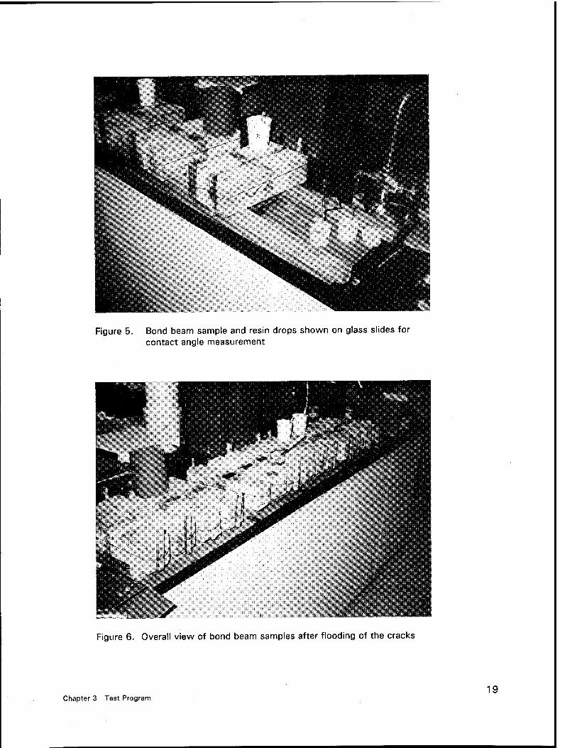
Figure 5. Bond beam sample and resin drops shown on glass slides for contact angle measurement
Figure 6. Overall view of bond beam samples after flooding of the cracks
Chapter 3 Test Program 19

as-molded was facing the operator. The load was applied continuously at a rate of 1,500 lb per minute until failure. The test results and rankings are shown in Table 6. The materials generally had low to very low bond strengths. Even after the 9 days of air curing, moisture was still noted along the bond interface after flexural testing. Most failures were bond failures between the resin and the concrete surface. Centerpoint flexural strengths greater than 350 psi generally had some moderate amount of fracturing of the concrete. Table C6 in Appendix C gives the raw data and descriptions of the failures. Photographs of the bond interface after testing are given in Appendix E.
Table 6 Summary of SSD Bond Strength Test Results
Product ID
Average Bond Strength
psi Experimental Rank
A 55 16
B 145 11
C 285 8
D 110 12
E 365 4
F 45 17
G 405 3
H 100 13
J 100 13
K 350 5
L 610 1
N 330 6
0 245 9
M 170 10
R 570 2
S 315 7
P 40 18
Q 60 15
The moisture of the specimens at the time the resin is applied is anticipated to be an important factor in this test. Visible moisture should not be present in the crack or on the specimen surface. Concrete absorbs water quickly but requires long periods to dry at room temperature. The time between removal of the specimens from the water until flooding with resin was typically 4 to
20 Chapter 3 Test Program
6 hr. During this time, additional water was not added to the samples, except for placing a damp towel over the specimens after the silicone cured. Even with this surface-drying period, the sawcut crack interface was still considered SSD. Since the surface-dried specimens were secured and sealed with silicone, the bond surfaces quickly regained surface moisture from bulk concrete and remained moist. The test is therefore considered severe, as the simulated crack interfaces were moist. Care must be taken to ensure that all specimens have the same surface moisture so the results can be compared.
21 Chapter 3 Test Program

4 Summary and Discussion of Results
Based on a literature review and discussion with experts and contractors, a test program was developed to evaluate the important properties of materials for injection of fine cracks in massive structures. Epoxy resins were selected for testing, based on recommendations of applicators and contractors. HMWM and ultrafine cements were also tested, because these materials hold promise for this application. The materials were tested for viscosity, pot life, sand column penetration, surface tension, contact angle, and bond strength to SSD concrete.
Each of the materials were ranked based on their relative performance in each of the tests. The summary of the test results is shown in Table 7, the summary of the ranks is shown in Table 8. The overall rank was developed based on the sum or cummulative points of all test results. Selection based on this cummulative rank assumes that each test criteria are equally important. Based on this assumption, Materials M, H, K, R, and N ranked in the top five, respectively. Samples M and R are HMWM resins, and samples H, K, and N are epoxies.
The following tabulation summarzies the three best materials in each test category.
Summary of Best Performers
Test
Material Designation
1 2 3
Viscosity Q/P1 M/R/S2 N
Pot Life Q/P2 D K
Penetration M2 H N
Surface Tension S/R/M2 H B
Contact Angle M2 0 R2
Bond Strength L R2 G
1 Ultrafine cements 2 HMWM resins
22 Chapter 4 Summary and Discussion of Results

X *< a> c
if> If) if) O If) in 10 o o o O o If) O o If) O O ** in ^> oa CO •* O o o 10 i— CO >* IV rv »— ^- CO (0 CM i— CO ■<t CO co co CM «— if> CO
■o c ._ 0 <0
ca a
a> o> c < "K (0 2 « TO fl]
0 d)
ro rv co o co co CO IV CO rv r- O co |v |v CO rv rv ^ o tv CM CM CM co en rv en r- T- co rv CO CM o o
o -8 CM CM CM co CO CM CO "" CM *~ CM CM *~ *~ CM CM CM
c o
°3 c » >- £ 0) Ü
jls •* CM CM o CO CO ,_ CO CO o CO If) ■* ID CO O CO CO
3 g. CO to en CO ,_ CO CM <t CO en CO O rv ■* o rv CO CO
(0 -u co CO CO <t ■* CO ■* CO <* CO CO ^- CO CO CO CM IV rv
If) In CM IV
11 o ~
CM X X
en rv en CO O rv CO If) ■* CO <* CO CO o
CM "o
CM
O
a. o a
■<t (0 CO CO CM CM CO if) O en IV o o V V a a > o r~ co *~ CM
r~ CO *~ * * CO CO
c _o ■a '^ c (0 a ** (0 + c CD CD CO en rv CM CD o CM <u u C <t o CO CO r- CO CO CO
Q. 5 LL ! j ! r— ! ■— [ i— ! «— »- «~ ! CM ! ! !
a. £ 0) —
T3 =
E E
E c (0
W '5 W
3 (0
5 (0 + + + ' + + + + + if) a co CM O o en O IV o rv o o o CO o o O if) IO
er *->
o CD CX3 >+ CO i— CO rv CO CO CO CO co o CO «— CO co t—
O CM *~ CM CM *~ CM CM CM CM CM CM CM '
(0 u H c
o (0 "£S 'z ,_ ,_ CO
+■> ca
c w co rv CO o lO O O o O CO If) ■* <* CM CO in If)
£ o
5 ^t co CM
CM CO CM CO CO CM
co en CO ■4- CM CM o o |c
•+- a) •- U E + + CO CO
en
o >«
CO
3
k. O
r* <o CO
o E C
S E 3 CO
2 «3 3 0
h- W £9 < CD U a LU U- CD I -) ^ _l Z O 2 or C/3 o_ O *~
Chapter 4 Summary and Discussion of Results 23

-* c (0
cc "5
> ,_ O iv <fr in ,— IV ■* CO <N CO in 00 t- CM IV T- O)
O r~ ""
a> > '^ (0
3 O ID o m in 00 ' in m m •* >* CM en co <* in m CO
CO CO 00 <0 IV CO 00 co 00 CO ■* ■* <*■ CM CO <* CO in
o £
.c O) c 01 ^ ** w
(0 ^_ 00 CM "fr |v CO co CO m ,- CO en o CM IV 00 in
c c o io
f— r- »- ■— *" *" "~ £0 EC
HI
o> c < u (a *• .* c c O (D u cc
O (O <t CD IV CM 00 ■<t ■* •* CM CM
en CM CO CM CO CO
c o '5 c 01 1- 01 Ü <0 _^ r c 3 (0 00 in O in m •* •* CO CD IV CM CO CO CM r- IV 00
(0 cc *~ *" r~ 1 *
>. *■»
'3
«/>
o „ ° c .» « > CC
CM m 00 ■* (0 - |v |v co 05 00 co O CM CM CM in -
OJ c -* c c o CO to
ÜC
"(5 c c CO IV in >* IV CO CM CM ■tf co CO o ,- en 00 00 m 0) (0
4-< c
E
Q. CC
k.
<u 01
a E X H .*
LU 0) <a 00 O 00 PI <fr IV rv in co CO T- co CM 01 co in <- ■-
*- o cc ■— »— *— *~ *~ *~ *~ r~ *~ O
>- k.
00 CD o
»£ ü
S E 3 73
(0 3 O
1- w ct < m u a UJ Li. u I —> ^ _l z O 2 CC CO 0- a
24 Chapter 4 Summary and Discussion of Results

The epoxy resins tested had a wide range of performance. For epoxies, resins K, H, N, L, and 0 had the best average performance in the tests. Resin N had the lowest measured viscosity of the epoxies, and samples D and K had the longest pot lives. Samples H and N had the best penetration for epoxies. Samples H, B, and O performed well in the surface tension and contact angle tests. Resins L, G, E, and K had the best average bond strength to SSD concrete for epoxies. The three most promising epoxy resins appeared to be K, H, and N. Sample K was good overall, but had fair rankings in viscosity and surface tension. The main weakness of sample H was the poor bond to SSD concrete. Sample N was good to fair overall but had a relatively high surface tension ranking. Sample L had the highest SSD bond strength and moderately good scores in the other tests and is worth considering where good bond is required. Further field testing of resins H, K, N, and L is warranted.
The test results on the ultrafine cements were mixed. The ultrafme cement mixtures had the lowest viscosity and the longest pot life, since they are suspensions in water and rely on hydration for hardening. They were weak in bond strength, even though they were allowed to cure 14 days compared to only 9 days for the resins. The ultrafine cements were also poor in penetration through the sand columns, even though they had long pot lives. They had a high surface tension, basically that of water. The tests that were developed were best suited for resin materials and may not be directly applicable to suspension in water. Overall, the performance of the ultrafine cements was promising, and further testing and field trails are warranted.
The HMWM resins performed very well in most of the tests. HMWM resins have lower viscosities than epoxy resins. A HMWM resin was in the top three ranks in each of the tests except gel time. They were best in sand- column penetration, surface tension, and contact angle. HMWM resins are currently formulated for use in the repair of cracks in bridges decks by gravity feed, where rapid cure times are desired to allow traffic to be returned in a timely manner. If necessary, HMWM resin formulations having longer pot lives can be developed specifically for the injection of fine cracks. Field testing of a standard formulation of HMWM and of a long pot life HMWM formulation is recommended.
Chapter 4 Summary and Discussion of Results 25
References
American Concrete Institute. (Annual). ACI manual of concrete practice. Detroit, MI.
American Society for Testing and Materials. (1994). 1994 Annual Book of ASTM Standards. Philadelphia, PA.
a. Designation C 33-92a. "Specification for concrete aggregates," 0.4.02.
b. Designation C 78-84. "Standard test method for flexural strength of concrete (using simple beam with third-point loading)," 04.02.
c. Designation C 192-90a. "Standard test method of making and curing concrete test specimens in the laboratory."
d. Designation C 293-79. "Standard test method for flexural strength of concrete (using simple beam with center-point loading)," 04.02.
e. Designation C 511-92a. "Specification for moist cabinets, moist rooms and water storage tanks used in the testing of hydraulic cements and concretes," 04.01.
f. Designation C 813-90. "Standard test method for hydrophobic contamination on glass by contact angle measurement," 15.02.
g. Designation C 881-90. "Specification for epoxy-resin-base bonding systems for concrete," 04.02.
h. Designation C 882-91. "Standard test method for bond strength of epoxy-resin systems used with concrete," 04.02.
i. Designation D 323-90. "Test method for vapor pressure of petroleum products (Reid Method)," 05.01.
j. Designation D 1331-89. "Standard test method for surface and interfacial tension of solutions of surface-active agents," 15.04.
26 References

k. Designation D 2393-86. "Standard test method for viscosity of epoxy resins and related components," 08.02.
/. Designation D 3278-89. "Test methods for flash point of liquids by Setaflash-Closed-Cup Apparatus," 06.03.
m. Designation D 3418-83 (1988). "Test method for transition temperatures of polymers by thermal analysis," 08.03.
Iisaka, T., Sugiyama, A., and Umehera, H. (1991). "Studies on penetration of repair materials for cracks in concrete," ACI SP-128, vol 1, 727-740, American Concrete Institute, Detroit, MI.
Kato, T., Umehera, H., and Yoshida, H. (1991). "Fundamental studies on inorganic materials for crack injection," ACI SP-128, vol 1, 707-726, American Concrete Institute, Detroit, MI.
McDonald, James E., and Campbell, Roy L. (1985). "The conduction of Corps of Engineers Civil Works concrete structures," Technical Report REMR-CS-2, U.S. Army Engineer Waterways Experiment Station, Vicksburg, MS.
Mirza, J., Popiel, M., Lacasse, J. R., Pelletier, M., Ballivy, G., and Salch, K. (1991). "Injectable cementitious materials for cracks in hydraulic structures," ACI SP-128, vol 1, 217-232, American Concrete Institute, Detroit, MI.
Moriconi, G., Pauri, M.G., Percossi, G., and Busto, S. (1991). "Influence of injected epoxy systems on the elastic and mechanical properties of cracked concrete," ACI SP-128, vol 1, 233-248, American Concrete Institute, Detroit, MI.
Plecnik, Joseph M., Gaul, Robert W., Pham, Mai, Cousins, Thomas, and Howard, Jeff. (1986). "Epoxy penetration," Concrete International 8(2), 46-50, American Concrete Institute, Detroit, MI.
State of California, Department of Transportation (Caltrans), Office of Transportation Laboratory. (1988). "Method of test for determining suitability of materials overlayment and repair of portland cement concrete pavements and structures," Manual of Test, Sacramento, CA.
The Aberdeen Group. (1994). "Perspective on epoxy injection," Concrete Repair Digest, Addision, IL, 171-174.
Trout, John F. (1991). "Quality control on the injection project," Concrete International 13(12), 50-52, American Concrete Institute, Detroit, MI.
References 27

Webster, R. P., Kukacka, L. E., and Elling, D. (1989). "In situ repair of deteriorated concrete in hydraulic structures: a field study," Technical Report REMR-CS-21, U.S. Army Engineer Waterways Experiment Station, Vicksburg, MS.
28

Appendix A Annotated Bibliography and Related Articles
A1 Appendix A Annotated Bibliography and Related Articles
Guidelines
• Causes, Evaluation, and Repair of Cracks in Concrete Structures
• Use of Epoxy Compounds With Concrete
• Guide for the Selection of Polymer Adhesives With Concrete
A2 Appendix A Annotated Bibliography and Related Articles

Section: 1
Author(s): ACI Committee 224
Title: Causes, Evaluation and Repair of Cracks in Concrete Structures
Reference: American Concrete Institute. (1993). ACI Manual of Concrete Practice. ACI 224.1R-90, Part 3. Detroit, MI.
Summary: The causes, evaluation, and repair of cracking are presented. Cracking in unhardened concrete may be caused by plastic shrinkage or settlement. The causes of cracking in hardened concrete discussed include: restrained drying shrinkage, thermal stresses, chemical reactions, weathering, corrosion of reinforcement, poor construction practices, construction overloads, errors in design and detailing, and externally applied loads. Suggestions for control of cracking are given. Evaluation of cracking by visual inspection, nondestructive testing, concrete core testing, and review of drawings and construction data are discussed. Based on the results of the evaluation and the determination of the cause(s) of cracking, guidelines are given for determining an appropriate repair procedure. The last section reviews these methods: epoxy injection, routing and sealing, stitching, additional rein- forcement, drypacking, crack arrest, polymer impregnation, overlays and surface treatments, high molecular weight methacrylates, and autogenous healing.
Corps Interest: The epoxy injection section gives general details about the
characteristics of cracks that are best repaired with injection, the types of structures that can be repaired with injection, and the procedures used in epoxy injection. A high degree of application skill and a suitable ambient temperature are key factors for satisfactory repair once the cause of the cracking has been determined. Cleaning the cracks is stressed. The general procedure for epoxy injection is: sealing the surface, installing entry ports (bonded flush fittings, drilled holes with fitting inserted or interruption seal), mixing, injecting, and removing the surface seal. Different injection pressures require different surface sealing procedures. Mixing the epoxy is accomplished by batching in a mechanically stirred paint-mixing-like setup or by a continuous procedure where mixing is done at the head/nozzle. Increased pressure often does little to accelerate the rate of injection and excessive pressure can propagate the existing cracks. Many other details are given in this article.
Keywords: Concrete, consolidation; corrosion; cracking (fracturing); drying shrinkage; epoxy resins; failure; mass concrete; methacrylates; mix proportioning; polymers and resins; repairs; sealing; settlement (structural); shrinkage; specifications
Appendix A Annotated Bibliography and Related Articles A3
Section: 1
Author(s): ACI Committee 503
Title: Use of Epoxy Compounds With Concrete
Reference: American Concrete Institute. (1993). ACI Manual of Concrete Practice. ACI 503R-89, Part 5. Detroit, MI.
Summary: Epoxy compounds have found a wide variety of uses in the concrete industry, such as coatings, grouts, binders, sealants, bonding agents, patching materials, and general adhesives. The properties, uses, preparations, mixtures, application, and handling requirements of epoxy resin systems when applied to and used with concrete and mortar are presented. The adhesiveness of epoxy and its chemical, thermal, and physical properties are given. Modification of these properties to accommodate given situation is reviewed. Problems encountered in surface preparation are reviewed, and procedures and techniques are given to ensure successful bonding of the epoxy to the other materials. Temperature conditioning of the base material and epoxy compound is outlined. The cleaning and maintaining of equipment are reviewed. Procedures to be followed in the application of epoxy compounds in several situations are given. The important factors which ensure that the epoxy compound will harden (cure) and therefore perform its function are discussed, together with alterations of the hardening rate. The allergenic and toxic nature of epoxies and the chemicals used with them create a hazard and precautions are detailed throughout the report.
Corps Interest: This detailed report begins with a history of epoxies. General
steps for resin injection are reviewed: surface sealing, entry ports, mixing, pumping, injecting, making sure crack is full, and removing surface seal. Underwater application is mentioned.
Keywords: Adhesion; adhesives; bonding; chemical analysis; cleaning; compressive strength; concrete; cracking (fracturing); epoxy resins; flexural strength, history; joints mix proportioning, mixing; patching; polymers and resins; repair; shrinkage; temperatures; tensile strength; underwater construction
"^ Appendix A Annotated Bibliography and Related Articles
Section: 1
Author(s): ACI Committee 503
Title: Guide for the Selection of Polymer Adhesives with Concrete
Reference: American Concrete Institute. (1993). ACI Manual of Concrete Practice. ACI 503.5-R-92, Part 5. Detroit, MI.
Summary: This guide provides the engineer, contractor, and architect with a description of the various types of polymer adhesives (epoxy, polyester, acrylic, polyurethane, polysulfide, silicone, vinyl acetate, and styrene butadiene) that are most frequently used for adhesive bonding of fresh concrete to cured concrete, repairing cracks in concrete, bonding concrete to other materials, and adhesive grouting of bolts and other inserts into concrete. The guide emphasizes the factors that should be considered when selecting a structural adhesive, including characteristics during installation and in service needs. The benefits and limitations of adhesive bonding are discussed for each application.
Corps Interest: A helpful glossary of terms and reference guide are given.
The two major classes of polymer adhesives (solvent-free and water-borne) are described with respect to their properties during application, during curing, and in the hardened state. Epoxy resins are in the solvent-free class. Details and the importance of working life, curing, viscosity, shrinkage, bond strength, creep resistance, and age hardening are some of the many properties discussed.
Keywords: Acrylic resins; adhesives; bolts; bonding; epoxy resins; fire resistance; latex; loads (forces); methacrylate; polymers and resins; polyester; polysulfide; polyurethane; repairs; serviceability; silicone resins; styrene-butadiene resins; toxicity; vinyl acetate; water-borne adhesives
A5 Appendix A Annotated Bibliography and Related Articles

General Techniques
How to Fix Cracks
Resin Filled Crack Injection Repairs
Repairs to Cracks in Concrete
Concrete Repair
Commercial Applications and Property Requirements for Epoxies in Construction
Epoxy Injection Welds Cracks Back Together
Quality Control on the Injection Project
Seal Cracks Carefully Before Injecting Epoxy Resin
A6 Appendix A Annotated Bibliography and Related Articles

Section: 2
Author(s): ACI Committee 224
Title: How to Fix Cracks
Reference: Concrete Construction. (January 1985). Vol 30, No. 1, 37-44
Summary: Successful crack repair procedures must be based on the cause and condition of the crack. Cracks caused by drying shrinkage are likely to stabilize, while those caused by foundation settlement will continue to grow. The following crack repair methods and their appropriate applications are discussed: epoxy injection, routing and sealing, stitching, adding reinforcement, drilling and plugging, grouting, flexible sealing, drypacking, polymer impregnation, overlays, and surface treatments. Each repair method is described and examples of where it might be useful are included.
Corps Interest: This article is a condensed version of "Causes, Evaluation and
Repair of Cracks in Concrete Structures," as reported by Aa Committee 224 in the Journal of the American Concrete Institute, May-June 1984 issue, which is summarized elsewhere in this annotated bibliography.
Keywords: Cracking; epoxy resins; plastics, polymers, and resins; repairs; sealing
A7 Appendix A Annotated Bibliography and Related Articles
Section: 2
Author(s): Boyes, Reg
Title: Resin Filled Crack Injection Repairs
Reference: Civil Engineering (London). (April 1985). 24-27
Summary: This article briefly summarizes the history of crack injection; the successes and failures of the first epoxy resin crack repair made on a California dam in 1959 are given. The problems of other materials like resorcinol resin combined with formaldehyde, and polyester resins are discussed. Important equipment and techniques are also described.
Corps Interest: This European article provides a history of crack injection
materials, equipment, and techniques. Polyester injection resins were reportedly about one-half the price of epoxy resins; however, the material can have higher shrinkage and curing problems.
Keywords: Bond; concrete; construction; cracking; epoxy resin; plastics; polymers; repairs; shrinkage strength
A8 Appendix A Annotated Bibliography and Related Articles

Section: 2
Author(s): Higgins, Denis
Title: Repairs to Cracks in Concrete
Reference: Concrete (Letterhead). (February 1983). Vol 17, No. 2, 26-28
Summary: Before repairing cracks in concrete, it is necessary to determine why the cracking occurred and if the structural safety, durability, watertightness, or appearance will be affected. Types of cracks are distinguished between dormant, live, and growing; the basic repair premise suitable to each situation is discussed. Position (location) and environment of the cracks also affect the choice of repair methods. The repair methods of resin injection, vacuum impregnation, polymer emulsion, cement-based materials, stitching, joints, bandaging, and surface coatings are outlined.
Corps Interest: This article from Europe reports that resin injection is normally
carried out by specialist contractors. An interesting table to assist in the selection of an appropriate method of crack repair is included in the article.
Keywords: Concrete durability; cracking (fracturing); permeability; repairs; safety
A9 Appendix A Annotated Bibliography and Related Articles

Section: 2
Author(s):
Title: Concrete Repair
Reference: Civil Engineering (London). (Supplement to April 1981 issue). 5-11
Summary: Repairing cracks promptly is important so that more extensive cracking and more serious problems can be avoided. Materials, techniques, and specialized contractors for repairing concrete are discussed. The techniques are guniting, vacuum impregnation, silicate system (mortar or concrete blended with a pure inorganic soluble silicate), and cathite method (general corrosion protection procedures). Repair materials include: epoxy adhesive, cement addition, certite (polyester) resin, epoxy injection materials, organic chemical treatments. A number of firms who have developed these techniques and materials are mentioned.
Corps Interest: British companies that have been involved in the development and
application of specialized epoxy systems may be interesting and a resource for Corps of Engineer projects. The Cement Crack Injection Unit, Sealocrete Products Kit, and Ciba-Geigy Araldite resin are mentioned.
Keywords: Adhesives; admixtures; chemical finishes; epoxy resins; impregnating; plastics; polymers; renovating; repairs; shotcrete
"1U Appendix A Annotated Bibliography and Related Articles

Section: 2
Author(s): Mendis, Peter
Title: Commercial Applications and Property Requirements for Epoxies in Construction
Reference: American Concrete Institute. (1985). "Polymer Concrete: Uses Materials, and Properties," (ACI) Special Publication, SP 89-7, Detroit, MI, 127-140
Summary: Almost every structure where concrete or steel is used is vulnerable to the corrosive effects of chemical and environmental attack, as well as mechanical abuse due to stress and vehicular traffic. Severe deterioration of such structures occurs in the commercial, industrial, and transportation areas. Epoxy, resin-based, polymer products are used for the rehabilitation, repair, and protection of both existing or newly constructed structures.
Corps Interest: Details about the variability of the chemical structure and
properties of epoxies are given. The versatility of epoxy formulations is demonstrated in the wide range of properties obtainable. Crack repair, crack injection, bonding new to old concrete, bonding various construction materials, overlays, coatings, underwater applications, and structural repairs using epoxies are discussed. The resin properties required for each application are presented.
Keywords: Adhesives; bonding; coatings; concrete construction; creep properties; epoxy resins; floors; grout; polymer concrete; rehabilitation; repairs; resurfacing
A11 Appendix A Annotated Bibliography and Related Articles
Section: 2
Author(s): Murray, Myles A.
Title: Epoxy Injection Welds Cracks Back Together
Reference: Concrete Construction. (January 1987). Vol 32, No. 1, 47-49
Summary: Low viscosity, insensitivity to moisture, and high bond, high compressive, and high tensile strengths are necessary for epoxy resins used for injection. Epoxy injection is one of the most effective ways of repairing narrow cracks. Repairs are made by cleaning the crack, sealing the surface of the crack, then injecting epoxy into it through ports spaced along the crack. Details about this procedure are given. Within minutes, epoxy can be injected 9 ft deep into cracks as narrow as 0.002 in. If structural repair of the crack is not necessary, the best way to seal active leaks is by injecting a chemical grout (such as Polyurethane). With wide cracks, low viscosity epoxies should not be used because the great amount of heat that is produced can cause the epoxy to boil or froth; low heat formulations are available and should be used. Viscosity is one of the most important properties to consider when choosing an epoxy. Equipment and quality control suggestions are given.
Corps Interest: The article provides good practical experience concerning resin
selection and injection techniques for deep cracks in massive structures.
Keywords: Concrete; crack; epoxy resin; injection; repair
"' . Appendix A Annotated Bibliography and Related Articles

r
Section: 2
Author(s): Trout, John F.
Title: Quality Control on the Injection Project
Reference: Concrete International. (December 1991). Vol 13, No. 12, 50-52
Summary: The resin injection process has more than a few skeptics. Specifiers have often been disappointed and embarrassed when assured results were not delivered. Specifications insisting upon years of experience, factory training, certifications, and licenses have not always helped. This article also appeared in the Concrete Repair Bulletin September/October 1993 issue.
Corps Interest: This article stresses that knowledgeable contractors do not need
detailed specification guidance; instead giving minimum crack width to be filled and depth of filling in a performance specification is adequate. Quality control is accomplished by coring; one to two cores for every 100 ft' is recommended. Tips for choosing a qualified contractor are given, including getting two verifiable references from a similar job with the current management and supervision. Many other practical details about contractor monitoring and spotting a poor contractor are given in this article.
Keywords: Contractors; injection; plastics, polymers and resins; quality control; specifications
1 A table of factors for converting non-SI units of measurement to SI units is present on p vii before the main text.
A13 Appendix A Annotated Bibliography and Related Articles

Section: 2
Author(s): Trout, John F.
Title: Seal Cracks Carefully Before Injecting Epoxy Resin
Reference: Concrete Construction. (June 1989). Vol 34, No. 6, 544-545
Summary: Failing to cap a crack properly before injecting epoxy resin can cause a leak that wastes costly resin. The leak also bleeds off pressure, reducing epoxy penetration and slowing progress of the repair operation. This article discusses causes of injection setup leaks and ways of avoiding them. Subjects covered include steps for capping the crack surface, stopping leaks, and removing the cap. Since most concrete has surface tensile strength of 75 psi, each linear inch of l-in.-wide cap will resist 75 lb of force. That's more than enough to prevent a cap from corning off under the pressures generated by normal injection procedures. For example, if a crack 0.005-in. wide is injected at a pressure of 200 psi, the force exerted against the cap is only 1 lb. The safety margin is 75 to 1.
Corps Interest: The steps for capping the crack surface are: clean the surface,
select the right cap material, carefully batch and mix the epoxy cap material, and apply the material avoiding strips and thin spots.
Keywords: Concrete; cracking; epoxy resin; injection; repair
A14 Appendix A Annotated Bibliography and Related Articles

Case Studies
Repairing a Major Concrete Navigation Lock
Crack Repair Techniques: To Bond or Not To Bond
Evaluation and Epoxy-Injection Repair of the Pier B-C Structure at Canada Place, Vancouver, B.C., Canada
Repairing Concrete With Polymers
Epoxy Injection of a Gate Pier
Delaminated Prestressed Concrete Dome: Investigation and Repair
Repair of Subsurface Voids in a High Performance Pavement
Rehabilitation of a Parking Garage
Concrete Bonding Process Saves Badly Cracked Dome Roof
Epoxy Injects New Life Into Bridge Pier
Appendix A Annotated Bibliography and Related Articles A15

Section: 3
Author(s): Barlow, Peter
Title: Repairing a Major Concrete Navigation Lock
Reference: Concrete International. (April 1986). Vol 8, No. 4, 50-52
Summary: Epoxy injection was used in the structural repair of the John Day Dam and Navigation Lock on the Columbia River. A major crack network was injected in six monoliths. About 440 lin ft of cracks up to 10 ft in depth were injected. Cracking was progressive from 1975 to 1979. The cracking was believed to be related to foundation settlement and surges due to the rapid filling and emptying of the culvert. The repair included cement grouting the soil, installation of high-capacity posttensioned rock anchors, and epoxy injection of the cracks. Holes with a diameter of 1-1/2 in. were drilled and flushed. Deferred bars were injected with epoxy grout tubes attached; the bars served as fillers and dowels across the joint. A biodegradable alkaline based detergent was introduced through the manifold to flush out river silts and clays. The solution also had a dye to help locate the cracks. The cracks were then flushed with water and blown with compressed air. Epoxy injection equipment capable of pressures up to 200 psi was used. The epoxy was high-strength, creep resistant, rapid curing, low viscosity, and had good bond to wet substrates. Approximately 600 gal of resin was used. The repairs have been successful and the rotation has stopped.
Corps Interest: Directly related to repair of massive structures that have
extensive cracking or rotations due to settlement.
Keywords: Anchor (fasteners); cracking (fracturing); epoxy resins; grouting; locks (waterways); reinforced concrete; repairs
A16 Appendix A Annotated Bibliography and Related Articles

Section: 3
Author(s): Guedelhoefer, O. C, and Krauklis, A. T.
Title: Crack Repair Techniques: To Bond or Not To Bond
Reference: Concrete International. (August 1986). Vol 8, No. 8, 10-15
Summary: The multiple and sometimes unique methods of repair that were applied to a tornado-damaged reinforced concrete cooling tower in Mississippi are presented. Damage was caused by multiple factors including: direct impact of the crane of the veil, transient loading, subsequent construction delays, and original structural problems near the base of the structure. These five sources/types of cracking required different repair methods which are discussed. Cracks that were considered to be unstable or moving, but still needed to be addressed to protect reinforcement, were fixed using an unbonded method. Recommendations for quality assurance/quality control and procedures to assure repair quality and durability are given. Conceptual guidance is provided for those involved in design in construction of concrete crack repairs.
Corps Interest: The article encourages that the general specification developed by
the engineer is best based on performance criteria, including regular monitoring and recording of pump pressure, mix ratio, and mix uniformity. For critical repairs, nondestructive testing using a V-meter and oscilloscope to determine if unfilled cracks are present is recommended. Prequalification criteria for contractors is also suggested.
Keywords: Bonding; cooling tower; cracking; damage; epoxy resin; nondestructive tests; quality control; reinforced concrete; repairs; shells; specifications; tunnels
A17 Appendix A Annotated Bibliography and Related Articles

Section: 3
Author(s): Gunnyon, G. K., and Morgan, D. R.
Title: Evaluation and Epoxy-Injection Repair of the Pier B-C Structure at Canada Place, Vancouver, B.C., Canada
Reference: American Concrete Institute. "Concrete in transportation," (1986). SP 93-24, 507-524
Summary: The Pier B-C structure in the inner harbor area of Vancouver was selected as the site for construction of the Canada Place Trade and Convention Centre. The project includes a five-berth cruise ship facility and a major 514-room hotel. The original Pier C was constructed by Canadian Pacific Railway between 1923 and 1927, and consisted of a central berm projecting 330 m (1,080 ft) from the shore, surrounded by a reinforced concrete deck supported by approximately 6,000 precast reinforced concrete piles driven into the berm. A detailed assessment of the structure showed that it was suitable, after rehabilitation of deteriorated areas, for use as the substructure for the Canada Place project. As construction progressed, substantial additional damage to the pier resulted from movements caused by installation of additional precast concrete piles and steel caissons to support the new structures. This paper describes the original assessment of the pier structure, evaluation of construction damage, and preparation of repair specifications. While extensive repair by shotcreting procedures was required, this paper concentrates on the epoxy injection repair aspects of the remedial work. Epoxy injection was used to achieve structural repair of reinforced concrete beams, piles, pilecaps, seawalls, and deck slabs.
Corps Interest: The widths of the cracks were typically greater than 0.020 in. but
narrowed significantly deeper into the structure. Most of the cracks were new and free of contaminants. Although the work was not considered technically difficult, many logistical problems were encountered. A specially formulated low-temperature resin was used. Bonded injection parts and automatic metering and mixing equipment were used. Complete filling was achieved by monitoring port-to-port flow, rather than specifying a maximum injection pressure. An extensive quality assurance program was used. The article lists the companies involved in this project.
Keywords: Concrete durability; concrete piles; corrosion; epoxy resins; evaluation; harbor structures; renovating; repairs; shotcrete
A18 Appendix A Annotated Bibliography and Related Articles

Section: 3
Author(s): Husbands, Tony B.
Title: Repairing Concrete With Polymers
Reference: The Military Engineer. (August 1985). Vol 77, No. 502, 426-427
Summary: Two Array facilities selected to demonstrate current technology using polymeric systems to repair concrete are described. The Office Chief of Engineers, through the Facilities Technology Application Tests Program, requested the Waterways Experiment Station to conduct this project. At Fort Bragg, North Carolina, a water tower with spalled concrete footings was repaired by injecting an epoxy resin under pressure into cracks and areas of delamination. Unsound concrete in a severely spalled footing was removed and restored to is original shape with fresh portland-cement concrete (PCC) bonded to the existing hardened PCC with an epoxy resin. A second Fort Bragg project repaired a multistory concrete building with corroded reinforcing steel and spalled and cracked concrete. Cracks were routed and sealed with a single-compound polyurethane joint sealant. Reinforcing steel was exposed, sandblasted or wire brushed, and coated with an epoxy resin before patching with latex-modified mortar. At Fort Ord, California, the concrete roof decks of two water-storage tanks showed spalling from reinforcement steel corrosion and numerous hairline cracks. Unsound concrete was removed to expose the reinforcement, the roof deck and exposed steel were sandblasted, all spalled areas were patched with a polyester mortar, and the roof deck was given a 3/4-in. coating of polyester resin after sealing with a neat polyester resin.
Corps Interest: Epoxy-resin injection was chosen at the water tower to repair the
cracks and delaminated areas of the footings because of its cost and because it was the most suitable method. Cracks that were at least 0.003 in. wide and clean were injected. Delaminated areas were outlined by sounding. Injection pressures of 100 to 500 psi were used.
Keywords: Concretes; corrosion; cracking (fracturing); mortars (material); patching; plastics, polymers and resins; reinforcing steels; repairs; spalling
Appendix A Annotated Bibliography and Related Articles A19

Section: 3
Author(s): McDonald, James E., and Logsdon, Donald, L.
Title: Epoxy Injection of a Gate Pier
Reference: Concrete International. (August 1986). Vol 8, No. 8, 34-38
Summary: Cracking along the top of a pier allowed infiltration of moisture into the mass concrete. Freezing and thawing resulted in deterioration of the nonair-entrained concrete. A test was conducted to evaluate the effectiveness of epoxy injection in mitigating the damage.
Corps Interest: The work was performed by the U.S. Army Corps of Engineers
to evaluate epoxy injection to repair cyclic freezing damage in nonair- entrained mass concrete.
Keywords: Bridge piers; concrete dams; cracking; deterioration; epoxy resins; reinforced concrete; repair
A20 Appendix A Annotated Bibliography and Related Articles

Section: 3
Author(s): Moreadith, F. L., and Pages, R. E.
Title: Delaminated Prestressed Concrete Dome: Investigation and Repair
Reference: American Society of Civil Engineers. (May 1983). Journal of Structural Engineering, Vol 109, No. 5, 1235-1249
Summary: A 3-ft-thick prestressed concrete nuclear power plant containment dome was discovered to be delaminated. The dome is steel lined and prestressed in three directions. The cause of the delamination was related to a compression-tension interaction due to the tendon stressing. Repairs consisted of epoxy injecting the cracks in the lower portion of the dome, providing radial anchors, and replacing the delaminated concrete near the upper cap. Cracks occurred at various depths within the dome. A grouting packer was used to inject the resin into the cracks at each depth.
Corps Interest: Cracks in the delaminated dome were injected using epoxy. The
cracks were parallel to the surface of the dome and at various depths. The l-in.-diam core holes were drilled through the dome, and a packer nozzle was used to inject each crack plane. Structural investigations and strengthening are described.
Keywords: Cracking; deformation; delamination; domes; epoxy resins; nuclear containment; prestressed concrete; repairs
A21 Appendix A Annotated Bibliography and Related Articles

Section: 3
Author(s): Murray, Myles A.
Tide: Repair of Subsurface Voids in High Performance Pavement
Reference: Concrete International. (March 1990). Vol 12, No. 3, 27-30
Summary: A series of voids occurred just below the surface of a concrete runway pavement due to consolidation problems. Small spalls were observed in the runway pavement surface after 1 year of service. Three repair techniques were used: replacement, scarify to below the voids and replacement with modified portland-cement concrete, and epoxy injection. Epoxy injection was used on the small areas of pavement. Tests indicated at by drilling holes 3 in. on center, 85 percent of the subsurface voids could be filled.
Corps Interest: Epoxy injection was effective in repairing subsurface voids in the
upper portion of the runway pavement even though many voids were not interconnected. Injection holes were core drilled with a vacuum attachment to prevent pulverized concrete powder from blocking the flow of the epoxy.
Keywords: Concrete; epoxy; injection; repair; consolidation; voids
A22 Appendix A Annotated Bibliography and Related Articles

Section: 3
Author(s): Ojha, Surendra K.
Title: Rehabilitation of Parking Garage
Reference: Concrete International. (April 1986). Vol 8, No. 4, 24-28
Summary: Extensive cracking in the floors of a seven-story parking structure was a cause of concern for its structural integrity. A structural capacity evaluation revealed undercapacity in beams and slabs and a load posting was recommended. The cracked floors were repaired by epoxy resin injection. The repairs are standing up well. Condition evaluation of the floors indicated some potential for corrosion of reinforcing steel. The floors are proposed to be protected partly by applying penetrant sealers and partly by installing a waterproofing membrane system.
Corps Interest: The repaired deck had a 4-in.-thick structural slab, overlain by a
1/2-in.-thick wearing surface. Crack width varied from fine to 3/4-in. Investigation into the cause of cracking concluded a predominant drying-shrinkage cause. A General Polymers #3517 resin with a viscosity of 300-350 cps, a tensile elongation of 2 to 5 percent, and a pot life of 30 to 35 minutes was used. The epoxy was injected from the underside of the slab at ports installed at 16-in. intervals. A constant injection pressure of 200 psi was used. Subsequent inspection of the repair revealed that none of the injection cracks had opened and no new cracks were formed; therefore, the cracks were confirmed to be dormant, as suspected.
Keywords: Chlorides; concrete slabs; cracking; epoxy resin; floors; garages; load tests; repairs; sealing
Appendix A Annotated Bibliography and Related Articles A23
Section: 3
Author(s): Smith, Anne
Title: Concrete Bonding Process Saves Badly Cracked Dome Roof
Reference: Concrete Construction. (November 1990). Vol 35, No. 11, 939-940
Summary: Buildup of gas pressure inside a containment of an anaerobic filter at the Highland Creek Treatment Plant in East Toronto, Canada, resulted in extensive cracking of the concrete dome. Replacement of the dome was considered. Since methane gas was leaking through the dome, a faster solution was required. The cracks and delaminations were bonded by epoxy injection. Different thicknesses of resin were used for the various width cracks. The roof had cracks from 0.004 to 0.040 in. wide. The base of the dome had cracks as wide as 0.25 in. The structural strength was restored to the dome and the gas leakage was stopped by epoxy injection. A second phase of repair was performed using a low-viscosity acrylic resin to seal the very fine cracks. The outside of the dome was sandblasted and the resin was spray-applied in several coats. Sand was broadcast into the wet acrylic resin and a gas-proof roofing membrane was applied.
Corps Interest: Epoxy injections were successful in rebonding cracks and
stopping methane gas leakage from the dome. The compatibility of an epoxy-injection resin and a low-viscosity acrylic resin was demonstrated. A gas-proof membrane was applied over the acrylic sealer.
Keywords: Concrete; cracking; dome; epoxy injection; repair
A24 Appendix A Annotated Bibliography and Related Articles

Section: 3
Author(s): Trout, John F., and Santangelo, Silvio
Title: Epoxy Injects New Life Into Bridge Pier
Reference: Concrete International. (August 1986). Vol 8, No. 8, 39-43
Summary: Repairs were made on a bridge pier for a highway linking Wisconsin and Minnesota. Fine cracks in the pier were injected vertically with a low-viscosity epoxy using socket mounting for the nylon injection nozzles. Injection began at the widest, rather than at the lowest crack. Careful materials handling and equipment maintenance were the keys to success. New formulations and sophisticated equipment and techniques were reviewed in good detail.
Corps Interest: The more advanced and reliable state of the epoxy industry in
1986 is illustrated with respect to materials, techniques, and equipment. A number of helpful details are given in this article. The project was conducted in the summer to take advantage of using a lower-viscosity epoxy. Socket mounted injection ports allowed water displaced by the injected epoxy to escape. The resin had a pot life of approximately 45 min at 75 °F. When high pressures were expected, the cracks were first primed with low viscosity resin, then sealed with age; no differences in bonding were observed. Pressures of up to 250 psi were expected. Injection was started at the widest section of the crack because it is suspected that it is easier to fill a fine crack from wider segment. The contractor remained at a port until back pressure was experienced. Lily and Sika were involved in this project.
Keywords: Bridge piers; cracking (fracturing); epoxy resins; repairs
Appendix A Annotated Bibliography and Related Articles A25

Experimental Studies
Performance of Epoxy-Repaired Concrete Under Thermal Cycling
Repaired Reinforced Concrete Beams
Evaluation of a Special Injector to Repair Structural Members
Two Simple Techniques for Testing the Performance of Repair Materials for Concrete Cracks
Epoxy Repair Techniques for Moderate Earthquake Damage
Influence of Injected Epoxy Systems on the Elastic and Mechanical Properties of Cracked Concretes
Shear Failure of Reinforced Concrete Beams and Effect of Repair by Epoxy Resin Injection
Epoxy Penetration
A26 Appendix A Annotated Bibliography and Related Articles

Section: 4
Äuthor(s): Al-Mandil, M. Y., Khalil, H. S., Baluch, M. H., and Azad, A. K.
Title: Performance of Epoxy-Repaired Concrete Under Thermal Cycling
Reference: Elsevier. (January 1990). Cement and Concrete Composites. Vol 12, No. 1, 47-52
Summary: Cracked concrete beams and slant shear cylinder specimens were bonded with epoxy, exposed to cyclic heating, and tested. Results indicated that cyclic heating and cooling adversely affected the flexural strength of the bonded beams. Three epoxy formulations were tested. The temperature cycle was 6 hr at 158 °F (70 °C) followed by 6 hr at 68 °F (20 °C). As the number of cycles increased, the failure location changed from completely within the epoxy resin. Large reductions in flexural strength were seen after 100 cycles and a lesser decrease from 100 to 150 cycles.
Corps Interest: This European research indicates that the bond and flexural
strength of the epoxy can be adversely affected by thermal cycling. Flexural beam tests may be appropriate for evaluating resins to be used in locations with cyclic heating.
Keywords: Thermal effects; beams; epoxy resins; adhesive bonding; repair
A27 Appendix A Annotated Bibliography and Related Articles

Section: 4
Author(s): Basunbul, I. A., Gubati, A. A., Al-Sulaimani, G. J., and Baluch, M. H.
Title: Repaired Reinforced Concrete Beams
Reference: American Concrete Institute Materials Journal. (July-August 1990). Vol 87, No. 4, 348-354
Summary: Thirty-six beams were cast. Repairs to cracked concrete beams were evaluated. Four methods of repair were studied: epoxy injection; ferrocement; steel-plate bonding, and the combination of epoxy injection and ferrocement. Epoxy injection restored the strength and ductility of the cracked beams. The ferrocement repairs exhibited higher flexural strengths but deceased ductility. The combination of epoxy injection and ferrocement was best to improve strength and ductility.
Corps Interest: Beams repaired by epoxy injection showed the same flexural
strength and cracking behavior as the original beams for all levels of damage. In a given situation, the dual nature of the problem, which entails restoring/enhancing structural integrity and making the repaired member durable, must be considered. Epoxy can restore integrity but does not enhance it. Ductility of epoxy-repaired members under thermal cycling is questionable.
Keywords: Adhesives; beams; bonding; cracking; ductility; epoxy resins; ferrocement; flexural strength; repairs; stiffness; strength
A28 Appendix A Annotated Bibliography and Related Articles

Section: 4
Author(s): Chung, C. Y, and Hwany, C. L.
Title: Evaluation of a Special Injection to Repair Structural Members
Reference: American Concrete Institute. (1991). Proceedings of the American Concrete Institute International Conference on Evaluation and Design of Concrete Structures and Innovation in Design. SP-128-16, Detroit, MI, 249-258
Summary: Concrete cracks wider than 0.1 mm (0.025 in.) should be repaired for safety and durability reasons. Epoxy injection repair can be difficult because the orientation and depth of cracks are frequently unable to be determined. The theory behind a specially designed spring injector to adjust and sustain an appropriate pressure was given.
Corps Interest: The reported good penetration attained by this specially designed
spring injector appears to be applicable to Corps of Engineer structures where the presence of debris is expected. The injection pressure can be adjusted by changing stiffness, length, or ring numbers. Detailed of the injection procedure are given.
Keywords: Cracking; epoxy resin; grout; injectors; repairs; splitting tensile strength; structural members; viscosity
A29 Appendix A Annotated Bibliography and Related Articles

Section: 4
Author(s): Fattuhi, N. I.
Title: Two Simple Techniques for Testing the Performance of Repair Materials for Cracks
Reference: Magazine of Concrete Research. (September 1983). Vol 25, No. 124, Wexham Springs, 170-178
Summary: Two test procedures were developed to evaluate crack sealing and repair materials. Grooves were formed by casting a 2-mm-thick plate into concrete prisms. The resulting simulated crack was filled with epoxy resins and mortars. They were tested in flexure at various temperatures. The second test used halved cylinders that were bonded and testing in splitting tensile. The half cylinders were formed by casting a sheet of plastic in the center of the cylinder mold. An increase in temperature resulted in lower tensile strengths for all systems tested, although one system tested was less sensitive to temperature.
Corps Interest: The test methods proposed are simple and may be useful in
evaluating epoxy resin formulations. Where elevated service temperatures are anticipated, testing should be performed at the elevated temperatures to ensure that significant strength loss does not occur. This is a European journal.
Keywords: cracking; concretes; epoxy resins; flexural strength; moisture; repairs
A30 Appendix A Annotated Bibliography and Related Articles

Section: 4
Author(s): French, W. F., Thorp, G. A., and Tsai, W. J.
Title: Epoxy Repair Techniques for Moderate Earthquake Damage
Reference: American Concrete Institute. (July-August 1990). ACI Structural Journal, Vol 87, No. 4, 416-424
Summary: Two test series were performed to evaluate epoxy injection repairs to moderately damaged concrete structures. Specimens subjected to simulated earthquake damage were repaired using epoxy injection or vacuum impregnation. Both techniques performed well in restoring the strength, stiffness, energy dissipation, and bond. Tests for penetration and wetability were performed on three resins with varing viscosity and potlife. A resin with an 80-min potlife and 2.4-poise viscosity was selected for both tests. The less viscous epoxy may be better suited for pressure injection. The vacuum impregnation procedure may be well suited for members with extensive cracking over large areas. Cracks with large widths tended to drain after vacuum impregnation, slightly reducing its effectiveness in restoring the beams energy dissipation. The repaired cracks did not reopen, but new cracks generally occurred. The bond between the steel and the concrete also appeared to be restored by the epoxy.
Corps Interest: Vacuum impregnation was as effective as injection techniques.
Impregnation may be better suited for repair of large areas than injection techniques. Epoxy resins were effective in repairing simulated earthquake damage to beam-column subassemblages.
Keywords: Vacuum impregnation; beams; bond; epoxy resins; earthquakes; joints; repairs; reinforced concrete; pressure injection
A31 Appendix A Annotated Bibliography and Related Articles

Section: 4
Author(s): Moriconi, G., Pauri, M. G., Percossi, G., and Busto, S.
Title: Influence of Injected Epoxy Systems on the Elastic and Mechanical Properties of Cracked Concretes
Reference: American Concrete Institute. (1991). "Evaluation and Design of Concrete Structures and Innovations in Design." Proceedings, ACI International Conference, Hong Kong. SP-128-15, Vol 1, Detroit, MI, 233-248
Summary: The concrete microstructure and crack width were important factors affecting resin injection. Successful injection of cracks greater than 0.8 mm was independent of the epoxy viscosity. For narrow cracks (less than 0.3 mm), resin viscosity is very important for adequate penetration. Concretes with various degrees of compaction were tested. Beams were fractured in center-point flexure and rebonded with epoxy. The test showed that great improvements could be obtained by epoxy injection of poorly consolidated and cracked concrete. The higher viscosity resin was best in sealing and bonding the samples with large voids and poor consolidation. The lower viscosity resin was better suited for tight cracks in well consolidated concrete.
Corps Interest: This research showed that the best performance was achieved
using the highest viscosity resin that would fill the cracks and voids. Consideration to the types of cracks and voids should be given before selecting an injection resin. A high-viscosity resin should be used to repair large cracks and poorly consolidated concrete.
Keywords: Cracking; epoxy resins; impregnating; strength; viscosity; elastic properties
A32 Appendix A Annotated Bibliography and Related Articles

Section: 4
Author(s): Ozaka, Y., and Suzuki, M.
Title: Shear Failure of Reinforced Concrete Beams and Effect of Repair by Epoxy Resin Injection
Reference: American Concrete Institute. (1986). "Concrete in Transportation," Detroit, MI, 637-670
Summary: Earthquake-damaged beams from a viaduct in Japan were repaired. Scale models were tested and the bending shear characteristics were examined. Repair methods included epoxy injection and injection with application of a bonded steel reinforcing plate. Cracking in the repaired beams occurred adjacent to the original cracks. The results indicated that a severely damaged beam could be repaired by epoxy injection to near or higher than its original capacity and deformability.
Corps Interest: The testing showed that earthquake damaged beams could be
successfully repaired using epoxy injection without the need for further reinforcement. The beam capacity was restored even though the injection may not have filled the minute cracks.
Keywords: Beams; failure analysis; repair; epoxy resins; shear damage
A33 Appendix A Annotated Bibliography and Related Articles

Section: 4
Author(s): Plecnik, Joseph. M., Gaul, Robert W., Pham, Mai, Cousins, Thomas, and Howard, Jeff
Title: Epoxy Penetration
Reference: Concrete International. (Feb 1986). Vol 8, No. 2, 46-50
Summary: Epoxy resins with a long pot life and low viscosity are required to provide optimum penetration and rebonding of reinforcing steel. The most important factors associated to penetration are resin viscosity, pot life, wetability, temperature, injection pressure, and crack size. A penetration test was developed to determine the depth of epoxy penetration into a dry sand or cement filled graduate by gravity. Pot life was determined to be a more important factor than injection pressure.
Corps Interest: It is important to identify the resin and application parameters
that affect penetration. Tests on pot life and viscosity are routinely performed on injection resins. A good test for resin wetability or surface tension is needed. Tests should be performed at a range of temperatures.
Keywords: Adhesives; bond; cracking; epoxy resins; penetration; reinforced concrete; repairs; viscosity
A34 Appendix A Annotated Bibliography and Related Articles
Other Materials
Studies on Penetration Properties of Repair Materials for Cracks in Concrete
Fundamental Studies on Inorganic Materials for Crack Injection
An Effective Repair for Leaking Waterstops
Repair of Cracked Concrete with High Molecular Weight Methacrylate Monomers
Crack Repair to Upper Stillwater Dam
Appendix A Annotated Bibliography and Related Articles A35

Section: 5
Author(s): Iisaka, T., Sugiyama A., and Umehera, H.
Title: Studies on Penetration of Repair Materials for Cracks in Concrete
Reference: American Concrete Institute. (1991). "Evaluation and Design of Concrete Structures and Innovations in Design." Proceedings American Concrete Institute International Conference, Hong Kong. Detroit, MI, SP-128-45, 727-740
Summary: Materials for repairing cracks which occur in concrete structures are discussed. Up to now, mainly organic materials have been used to repair cracks, but these materials have problems, including heat resistance and durability. To overcome these problems, blast furnace slag cement was used as an impregnating material by pulverizing it to an ultra-fine powder with a specific area almost three times that of normal cement. The viscosity of the blast furnace cement paste with a water-cement ratio equal to 70 percent is almost the same as epoxy resin. Consequently, the paste in ultra-fine blast furnace slag cement was expected to penetrate cracks like epoxy resin and may be a suitable repair material.
Corps Interest: In addition to the ultra-fine slag cement, an epoxy resin with
varying amounts of dilutant was also evaluated for comparative purposes. Some of the properties of these materials were given. Comparisons of crack width to permeability and viscosity to penetration were made. The experimental method used in this work may be useful in other Corps of Engineer projects. Procedures for crack inducement and crack simulation with two glass plates are detailed. The glass plate testing was complicated by capillary force, surface tension, coefficient of friction, and width of paving aperture.
Keywords: Blast furnace slag; cement; cracking; impregnating; penetration tests; repairs; viscosity
A36 Appendix A Annotated Bibliography and Related Articles

Section: 5
Author(s): Kato, T., Umehare, H., and Yoshida, H.
Title: Fundamental Studies on Inorganic Materials for Crack Injection
Reference: American Concrete Institute. (1991). Proceedings, American Concrete Institute International Conference, Hong Kong. Detroit, MI, SP-128-44, 707-726
Summary: Organic materials, such as epoxy resins, are reported to deteriorate after long-term exposure to the environment and do not bond well to wet cracks. Ultrafine slag cement was compared to epoxy resins for repairing cracks. The tests identified problems of bleeding and drying-shrinkage of slag cement grout due to high water contents. Their use was satisfactory when they contained low water contents and a superplasticizer. Sawcuts, 3 mm wide, were cut halfway through the beams. The sawcuts were filled in both dry and wet conditions and cured at temperatures of 20 or 50 °C. The flexural strength of the beams repaired with epoxy approached the uncracked beams when injected in dry cracks and aged to 28 days. A reduction in strength was seen when the cracks were wet when injected, but the strengths improved with aging in a dry environment. Resins designed to be used on wet concrete can restore full strength when injected into wet cracks and allowed to cure in a drying environment for 28 days. Only 50 percent of the strength of the beams was recovered using ultrafine cement grout. The grout was generally unaffected by wet or dry bond surfaces and curing temperature.
Corps Interest: Ultra fine cement may be a practical material for crack injection.
It is stable for a variety of moisture conditions and temperatures. Corps special interest would be in repairing cracks that are continuously wet. Ultra fine cements are less expensive and more compatible with the concrete structure. However, the strength increase was much less than with epoxy and only 50 percent of the uncracked beams.
Keywords: Beams; blast furnace slag; cracking; epoxy resins; repairs; inorganic compounds
Appendix A Annotated Bibliography and Related Articles A37

Section: 5
Author(s): Kostyk, Barry W., and Parnell, James E.
Title: An Effective Repair for Leaking Waterstops
Reference: Concrete Construction. (June 1984). Vol 29, No. 6, 594-596
Summary: Hydrophilic polyurethane foam grout is injected into a joint containing water. The resin reacts with the water resulting in a foam that forms a water stop. It is reportedly durable to freezing and thawing and cyclic wetting. The resin viscosity is between 300 and 600 centipoise. Injection techniques are described.
Corps Interest: Water reactive urethane foam grouts provide a method to stop
cracks with active water leakage. They do not structurally bond the cracks but fill the cracks with a flexible foam. Structurally bonding leaking cracks is the most difficult crack repair procedure and the urethane foams can be used in conjunction with epoxy resins to first stop the water flow by injecting behind the crack with urethane, and second to bond the crack with epoxy.
Keywords: Bonding; foaming agents; grout; joint sealers; polyurethane resins; repairs; waterproofing
A38 Appendix A Annotated Bibliography and Related Articles

Section: 5
Äuthor(s): Rodler, D. J., Whitney, D. P., Fowler, D. W., and Wheat, D. L.
Title: Repair of Cracked Concrete with High Molecular Weight Methacrylate Monomers
Reference: American Concrete Institute. (1989). "Polymers in Concrete: Advances and Applications," SP-116-9, Detroit, MI, 113-128
Summary: Three high-molecular-weight methacrylate resins (HMWM) were tested to determine their effectiveness in repairing cracked concrete slabs, beams, and tensile specimens. All resins increased the stiffness of the beams and filled cracks as small as 0.1 mm. However, the performance of each resin was adversely affected by moisture and high temperature. The resins placed at temperatures over 100 °F cured rapidly reducing the penetration. Saturated concrete having cracks that could drain from the bottom required 2 to 3 days of drying prior to treatment to achieve good bond. In saturated slabs with cracks that do not drain, 7 days of drying was recommended.
Corps Interest: Selecting a resin with the proper modulus is important for crack
repair. This area is controversial among repair specialists. Higher- modulus, more rigid resins failed at higher stress but with less strain. The testing indicated that higher-modurus resins were best suited for repair of nonmoving fine cracks. The lower-modulus, more flexible resins may be best suited for beam repairs where movement is important. Proper drying of wet cracks is important for good penetration and bond.
Keywords: Beams; concrete slabs; cracking; methacrylates; repairs; high- molecular-weight methacrylate
Appendix A Annotated Bibliography and Related Articles A39

Section: 5
Author(s): Smoak, Glenn W.
Title: Crack Repair to Upper Stillwater Dam
Reference: Concrete International. (February 1991). Vol 13, No. 1, 33-36
Summary: Upper Stillwater Dam in Utah was constructed of roller compacted concrete. To facilitate construction, the dam design did not include contraction joints. Foundation deformation and concrete cooling enhanced the formation of cracks in the dam. One crack was leaking 1,300 gal/min of water. The repair of the cracks using pressure injection of a flexible hydrophilic polyurethane resin is described in this article.
Corps Interest: The repair was conducted in threes stages. The main emphasis of
the first stage was to control or cut off the flow of water into the foundation gallery work area, using valved injectors, urethane-soaked jute rope, and other techniques. Stage two was the major work item in the crack repair and consisted of deep injection from the downstream face. The third stage involved injecting the upstream face. Water-to-resin ratios varied depending on how much water was or was not in the cracks. Specific details of the procedure are given in the article.
Keywords: Concrete dams; cracking (fracturing); polyurethane resin; repairs; roller-compacted concrete
A40 Appendix A Annotated Bibliography and Related Articles

Related Articles
Adin, Moshe, A., Yankelevsky, David Z., and Farhey, Daniel N. (1993). "Cyclic behavior of epoxy-repaired reinforced concrete beam column joints," American Concrete Institute Structural Journal 90(2), 170-179.
American Society of Civil Engineers. (1986). "Rehabbing Research," Civil Engineering 56(9), 55-57.
Bononi, A., Borreill, J., and Mouton, Y. (1986). "Effect of water on epoxy binders utilized in repair by injection." Proceedings of an International Symposium: Adhesion Between Polymers and Concrete. Aix-en-Provence, France, RILEM, Chapman & Hall, NY (in French), 390-397.
Colle, E. R. (1993). "Repairing the Newport Hydroelectric Station," Concrete International 15(3), 42-46.
Concrete Plant and Production (Amersham). (1988). "Assessment of crack injection repair of reinforced concrete," 6(4).
Eadara, R., Armbruster, R., and Davies, P. (1989). "Epoxies in concrete maintenance." Proceedings 34th International Society for the Advancement of Material and Process Engineering Symposium and Exhibition - Tomorrow's Materials: Today. Covina, CA, 1704-1714.
Engineering News Record. (1991). "Arch Dam cracks repaired," 207(12), 42.
Fattuhi, N. I., and Hughes, B. P. (1985). "Testing repair material for concrete cracks," Durability of Building Materials (Amsterdam) 3(1), 59-75.
Field, Jonathan S. (1986). "Rehabilitation of Victoria Dam." Proceedings of an International Conference on Hydropower: Waterpower. American Society Civil Engineers, New York.
Gerwick, Ben C. (1982). "Causes and prevention of problems in large-scale prestressed concrete construction," Journal Prestressed Concrete Institute 27(3), 58-75.
Grosskurth, K. P., and Perbix, W. (1986). "Improvement in the durability of cracked concrete elements injected with synthetic resin by optimizing the bond behavior." Proceedings of the International Symposium: Adhesion Between Polymers and Concrete, RILEM, Chapman & Hall, New York, 403- 409.
Hewlett, P. C, and Morgan, J. G. D. (1982). "Static and cyclic response of reinforced concrete beams repaired by resin injection," Magazine of Concrete Research (Wexham Springs) 34(118), 5-17.
Appendix A Annotated Bibliography and Related Articles A41

Jones, Joe P., and Gibson, Ronald F. (1987). "Concrete arch bridges get total restoration," Roads and Bridges 25(8), 58, 67-68.
Kay, Ted. (1992). Assessment an renovation of concrete structures. Longman Scientific & Technical (copublished by Wiley) Essex.
Letsch, R. H. (1986). "Resin injection of cracks with changing width." Proceedings of the International Symposium: Adhesion Between Polymer and Concrete, RILEM, Chapman & Hall, New York, 432-438.
Mailvagnam, Noel P. (1992). Repair and protection of concrete structures, CRC Press Inc., Boca Raton.
Mansur, M. A., and Ong, K. C. G. (1985). "Epoxy-repaired beams," Concrete International 7(10), 46-50.
Moksne, S. J. (1981). "Resins in construction and repair of North Sea oil structures," International Journal of Cement Composites and Lightweight Concrete (Harlow) 3(3), 203-211.
Ozaka, Y., and Suzuhi, M. (1986). "Shear failure of reinforced concrete beams and effect of repair by epoxy resin injection," Concrete in Transportation, American Concrete Institute, Detroit, MI, SP-93, 637-640.
Paillere, A. M., and Jaizairi, B. El. (1991). "Standard activity for protection and repair of structures in Europe." Proceedings of the American Concrete Institute International Conference: Evaluation and Design of Concrete Structures and Innovations in Design. Hong Kong, ACI SP-128, Detroit, MI, 741-748.
Popovic, Predrag L., and Klein, Gary J. (1988). "Shear collars save a parking garage slab," Concrete Construction 33(10), 924, 927, 228.
Shanafelt, G. O., and Horn, W. B. (1985). "Guidelines for evaluation and repair of prestressed concrete bridge members," National Cooperative Highway Research Program Report 280.
Shanklin, Donald W. (1984). "Repair of concrete water resources structures by epoxy materials." Proceedings American Society of Agriculture Engineers Winter Meeting: Engineering the Future - Capitalizing On the New Technologies. ASAE, St. Joseph, MI.
A42 Appendix A Annotated Bibliography and Related Articles

Appendix B Manufacturer's Data
B1 Appendix B Manufacturer's Data

B2
r*. L0 r-«. to o CO *t O 0) CO LO CO CO o CO o o o L0 t- ffi o o L0 O
O CD ^- CO o CM LO CO CO r** CM <t CM o CM a> o CO r». LO CO ffi CO o ■* o
CM O o «tf- (0 0) CM CO * O LO CN CO CD ^t CO o O r- rx CO o o ^- LO
t CO
o CO r* CO co 9 CO o rv T~ 10 O CO 03 10 *^" O CM CM CO *7 *f ? CD CM CM CO ,1 LO ± CD ■<t CO LO to T- CO CM CO s r» CO to 4 CO CO CM CO ^ o 10 CO CO CM Tf 03 CD CO en * < co 03 CO CO L0 •* ■* CO r» CM CO CO CO
2
1 tO op 00 r^. op CO CO CO 03 CM CO CO CM CM CO CO ffi CM ffi CO LO ffi CM CO CO (0
^ ID ■«t o ö ö Ö 4 6 CO «t 6 CD CD 4 6 r- CO oS 4 CO CO CO *t *t ob o o o o o o o o o O o o o o *- o r- O
£ 5 rv CO 03 00 09 4- CO LO r- 00 CM r^ •* CO CM r-- CM 4> co CM r- ffi r^- r^
u V w ^ 1 >- I
„ & a. Q. a.
«
a a
V
o. a a a a £ O. 3 a a a a a a a
£ >
11 E £ to <o
> > e to
> E <o
TO
"> E
a. E
1 .3
E E a a
> > E
> E re > 0
>■
E 9
>■
V i >■
E a
>■
£
> a E
a £
£ to
> £
> E E
> > TJ -D ■D TJ -5 TJ ■o ■o -o *o ■5 "O •o ■6 ■o ■a ■o ■o ■o -O 3 ■o ■u ■D TJ "O
£ 3 a
i E u o o o LO r* o O o o o O O o o ffi H ^t LO r*. CO CD ^t CM ** ■* •* "* LO LO to
£ 3
m a a i* LO L0
CM ffi LO CO
H E o "~
1 1 (0
(D CM CM Tt CO CM f •* ■* ^i -<t -<t CO CM
n 2 CO CM <- *" CM CM CM CM CM CM *- *~
c 0 CM
'.p a 0 n
o
2 a
o r- ID O
03 q
CO CM
LO L0
LO 00
CO ffi i ■D -p o" d d *- — d *- d
it •> £ o
CM
LO
a CM LD o LO O o o o Ö LO LO
Z O CO CO CO CO CO 00 CO CO CO 00 !•*■
t a
% CO q
o # d
r- M CM O
TJ h- C o x O tu
O» z w <
o o o
2 c 0)
LL o L0
o q
CO co_
«S CO U) S. < u CO *t r>T
■£ </) o» O o o o
'55 V
n « (0
c CM co r- Q
o o co_ q
m"
o CO
LO"
CO
> X
"£ ^ o o o o O O o o o o o o <t O o o o at o o o o o o o o CO o o o CO o o o
3 c £ » a.
O 0) r»
L0 q L0 *t q q q q 03 o LO ** CO_ « o o o_ o 0) CM" CM CM •* ■* *-" CM" CO" CO L0" d LO" co" co" L0~ LO ^-" a
LU 1L a *- •" r- r- "~ *" *~ *~ p*- r-
k. c o
O 0) •*3 iq M- 'B a» to
s o
CO L0 LO 5? Ti- f-; r*; L0 LO cq CO LO Cp ^
IQ c O o LO CN CO ffi A co' ^ CM CM LO CM CO CO to r^ LO CM CO CO »- r^ L0 CO LO ID CO
(0 H m # a V-
o O o
q +* ffi" o 3
£ o o o o o o o o o L0 o o o o o O o o o o o o o o o d J5 a o o o o o o o o o o o o o o LO o o o o r*. o p* o o o
■D '5 c £ —
CO M <0
r-. q L0_ q q q q o q ■* o q q CM L0_ CM t*> q o ffi «* CO q CD O
O c 0) co" <n" r-~ ffi" to ro r-" o~ co" LO" ffi" LO" co" to r-~ co" co" (D *-" r-" co" co" ■^■" to" oo"
a. H u) a o r~
>• v> w o o m
> i o _J
3 O
Ü
CO <_> O
c o & >
ca V .Q
1-
a> k-
3 +■* U (0
»♦- 3 C ffi 2
« 5 a c
■5 c Ul
B a 0 o
O CM to o (0 0) 4« LU
s
o 3
CO (0 LO
m
> in
1 < o
Ö o
o f
o a V c V a
d z X o a. « >
LU
tr c o
* 5 S =>
ST"? o o a ^ o o o i:
5 2 Dec
o-R
ex
Inje
ct X
LV
SC
B C
oncr
esiv
e 13
6
o
o CM
s (0 CD ffi CO
LU
CM o 00
CJ ce V
u
U
w
DC
V
E V 0.
CM
o
a
5
> _i
o o
ft o V
'? o
o o o
or
o
£
o <
cc
CM LO
3 "O (0
CO
wJ
I 3
CO
o LO
> X 0 0- 6
CM
d z
n
E c
CO
CO o CO
CO c to o
CC u u cc
LO CO CO
"3 3 Q
CM
d z
LO
_J CO
z. > ^ _J
u «
2 ? 4! S 5 or
Appendix B Manufacturer's Data

Table B2 Typical Manufacturer's Product Data
Microfine Cement
Specific gravity 3.00 ± 0.10 Apparent bulk density (kg/L) 1.00 ± 0.10 Blaine specific area (cm2/g) 9,000 to 13,000
Viscosity varies 5 to 50 cps
Permeability (cm/sec) 10"7 to 10"9 (approximate)
High-Molecular-Weight-Methacrylate
Viscosity (ASTM D 2393)1 less than 20 cps
Specific gravity 1.025 at 60 °F(15 °C)
Density 8.5 to 8.9 lb/gal
Flashpoint (ASTM D 3278)1 greater than 200 °F (95 °C)
Vapor pressure (ASTM D 323)1 less than 1.0 mm Hg at 77 °F (25 °C) Tg (OSC midpoint (ASTM D 3418)1 175 to 200 °F (80 to 95 °C)
Pot life 30 minutes minimum
Gel time 1 to 2 hours at 72 °F (22 °C) Bond strength (ASTM C 882)1 1,500 psi (10.3 MPa) minimum
Tensile strength (neat) 700 psi (4.8 MPa) minimum (14-day postcure)
1 References are listed following main text.
Appendix B Manufacturer's Data B3

Appendix C Raw Data From Testing
C1 Appendix C Raw Data From Testing

Table C1 Raw Data for Viscosity of Resins
Product ID RPM Average Reading Factor Viscosity
A
6 12 30
14.8 29.7 74.0
10 5 2
148.0 148.5
148.0
B
6 12 30
18.1 33.3 83.7
10 5 2
181.0
167.0 167.0
C
6 12 30
38.0 73.7
+ 100
10 5
380.0
369.5
D
6 12 30
14.0
32.5 72.3
10 5 2
140.0
162.5 144.6
E
6 12 30
22 42 98
10 5
220 210
F
6 12 30
12.5 25.3 65.3
10 5 2
125.0 126.5 130.6
G
6 12 30
34.4 65.6
+ 100
10 5
344.0 328.0
H
6 12 30 60
<10 17.0 42.6 85.1
5 2 1
85.0 85.2 85.1
J
6 12 30
15.4 30.8 77.4
10 5 2
154.0
154.0 154.8
K
6 12 30
10.7 21.2 54.0
10 5 2
107.0 106.0 108.0
L
6 12 30 60
11.5 18.8 44.0 87.5
10 5 2 1
115.0 94.0 88.0 87.5
N
6 12 30 60
<10 15.2 38.7 79.1
5 2 1
76.0 77.4 79.1
0
6 12 30
11.8 21.5 54.3
10 5 2
118.0
107.5 108.6
C2 Appendix C Raw Data Form Testing
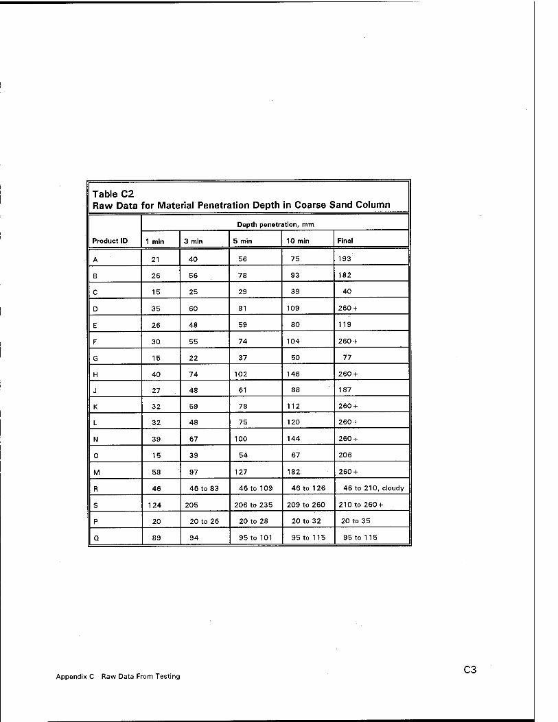
Table C2 Raw Data for Material Penetration Depth in Coarse Sand Column
Product ID
Depth penetration, mm
1 min 3 min 5 min 10 min Final
A 21 40 56 75 193
B 26 56 78 93 182
C 15 25 29 39 40
D 35 60 81 109 260 +
E 26 48 59 80 119
F 30 55 74 104 260 +
G 15 22 37 50 77
H 40 74 102 146 260 +
J 27 48 61 88 187
K 32 59 78 112 260 +
L 32 48 75 120 260 +
N 39 67 100 144 260 +
0 15 39 54 67 206
M 58 97 127 182 260 +
R 46 46 to 83 46 to 109 46 to 126 46 to 210, cloudy
S 124 205 206 to 235 209 to 260 210 to 260 +
P 20 20 to 26 20 to 28 20 to 32 20 to 35
Q 89 94 95 to 101 95 to 115 95 to 115
Appendix C Raw Data From Testing C3

Table C3 Raw Data for Material Penetration Depth in Fine Sand Column
Product ID
Depth Penetration, mm
1 min 3 min 5 min 10 min Final
D 13 25 32 44 146
F 16 26 33 49 103
H 18 33 42 57 189
K 16 26 34 47 167
L 16 28 35 55 112
N 19 32 41 59 186
M 51 89 125 163 260 +
S 27 42 44 to 57 44 to 62 44 to 62
C4 Appendix C Raw Data Form Testing

Table C4 Raw Data for Surface Tension Tests
Product ID
Surface Tension Readings, dynes/cm
1 2 3 Average
A 38.0 38.8 38.5 38.4
B 35.7 35.5 37.3 36.2
C 38.9 39.2 39.4 39.2
D 43.0 43.0 43.0 43.0
E 41.5 41.5 41.7 41.6
F 39.8 39.8 39.7 39.8
G 41.7 42.4 42.1 42.1
H 34.5 34.6 34.7 34.6
J 43.4 44.0 43.4 43.6
K 38.7 39.1 39.1 39.0
L 38.6 38.3 38.1 38.3
N 40.6 40.5 40.3 40.5
0 37.6 37.4 37.3 37.4
M 34.0 34.8 34.7 34.5
R 29.7 30.8 304 30.3
S 27.8 26.6 26.7 27.0
P 75.9 75.8 77.2 76.3
Q 79.7 74.0 76.8 76.8
Appendix C Raw Data From Testing C5

Table C5 Raw Data for Contact Angle Tests
Product ID Reading 1 Reading 2 Reading 3 Average Reading
A 23 18 23 21.3
B 22 21 19 20.7
C 27 27 28 32.0
D 28 37 31 32.0
E 34 32 31 32.3
F 24 21 22 22.3
G 33 32 35 33.3
H 20 24 15 19.7
J 30 29 23 27.3
K 21 19 19 19.7
L 19 22 24 21.7
N 20 20 23 21.0
0 11 15 14 13.3
M 9 7 7 7.7
R 17 17 22 18.71
S 20 25 22 22.31
P ._ — 20.71
Q 20 21 21 20.7
1 Used data from Q
C6 Appendix C Raw Data Form Testing
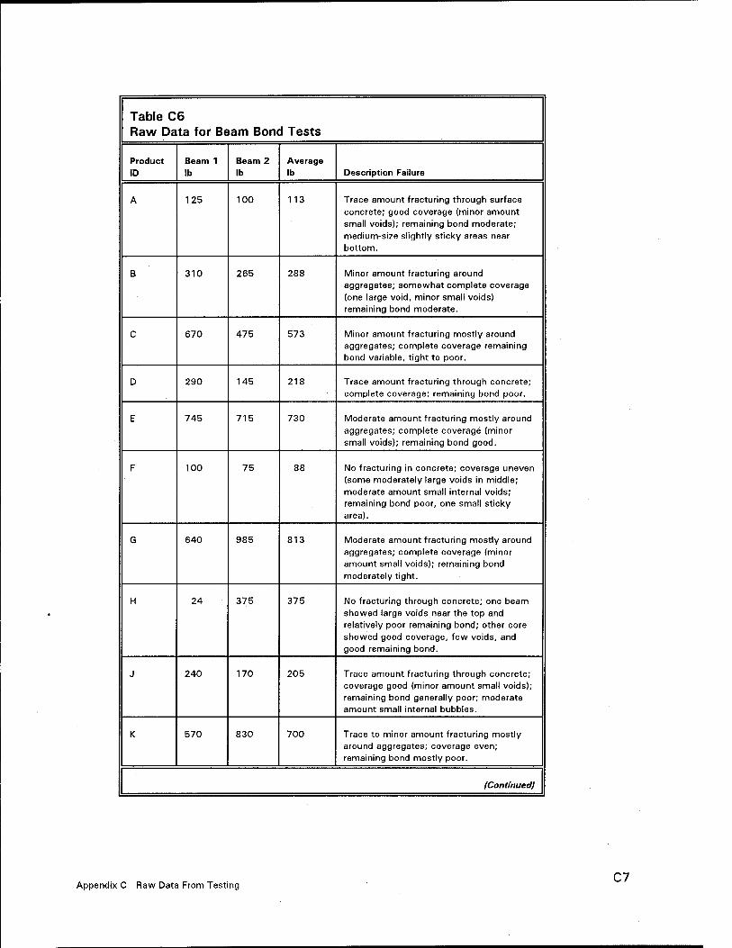
Table C6 Raw Data for Beam Bond Tests
Product ID
Beam 1 lb
Beam 2 lb
Average lb Description Failure
A 125 100 113 Trace amount fracturing through surface
concrete; good coverage (minor amount small voids); remaining bond moderate; medium-size slightly sticky areas near bottom.
B 310 265 288 Minor amount fracturing around aggregates; somewhat complete coverage (one large void, minor small voids) remaining bond moderate.
C 670 475 573 Minor amount fracturing mostly around aggregates; complete coverage remaining bond variable, tight to poor.
D 290 145 218 Trace amount fracturing through concrete; complete coverage; remaining bond poor.
E 745 715 730 Moderate amount fracturing mostly around aggregates; complete coverage (minor small voids); remaining bond good.
F 100 75 88 No fracturing in concrete; coverage uneven (some moderately large voids in middle; moderate amount small internal voids; remaining bond poor, one small sticky area).
G 640 985 813 Moderate amount fracturing mostly around
aggregates; complete coverage (minor amount small voids); remaining bond
moderately tight.
H 24 375 375 No fracturing through concrete; one beam
showed large voids near the top and relatively poor remaining bond; other core showed good coverage, few voids, and good remaining bond.
J 240 170 205 Trace amount fracturing through concrete; coverage good (minor amount small voids); remaining bond generally poor; moderate amount small internal bubbles.
K 570 830 700 Trace to minor amount fracturing mostly around aggregates; coverage even; remaining bond mostly poor.
(Continued)
Appendix C Raw Data From Testing C7

Table C6 (Concluded)
Product
ID
Beam 1
lb Beam 2
lb
Average
lb Description Failure
L 610 1,830 1,220 One beam showed moderate amount
fracturing through mostly concrete in one area only; other beam showed fracturing through an abundant amount of concrete
throughout.
N 520 795 658 Approximately half of fracturing through mostly shallow surface concrete;
coverage variable, one beam had complete coverage, other beam had a
large void in upper half; remaining bond in
both beams variable.
0 670 310 490 Minor to moderate amount fracturing mostly around aggregates in near-surface
zone. Coverage somewhat uneven with minor to moderate amount small voids and
one relatively large void; remaining bond
tight to weak.
M 270 410 340 Approximately half of fracturing through shallow concrete; complete coverage;
remaining bond good.
R 812 1,459 1,136 Minor amount fracturing through concrete, moderate to somewhat fracturing within resin; complete coverage; remaining bond
good; resin slightly flexible.
S 670,483 739 631 No fracturing through concrete, most fracturing within resin; complete coverage; remaining bond moderately
good; resin somewhat elastic.
P 60 100 80 No fracturing through concrete, most
fracturing within paste; uneven coverage; remaining bond weak (material soft).
Q 135 115 125 No fracturing through concrete, mostly fracturing within paste; uneven coverage (moderate amount relatively thinly coated
large voids); remaining bond weak
(material soft.
C8 Appendix C Raw Data Form Testing

Appendix D Draft Bond Test Procedure
D1 Appendix D Draft Bond Test Procedure
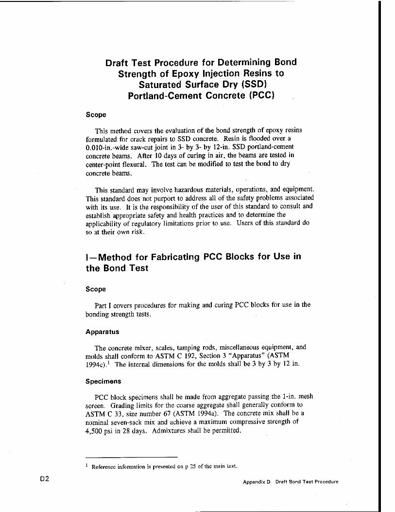
Draft Test Procedure for Determining Bond Strength of Epoxy Injection Resins to
Saturated Surface Dry (SSD) Portland-Cement Concrete (PCC)
Scope
This method covers the evaluation of the bond strength of epoxy resins formulated for crack repairs to SSD concrete. Resin is flooded over a 0.010-in.-wide saw-cut joint in 3- by 3- by 12-in. SSD portland-cement concrete beams. After 10 days of curing in air, the beams are tested in center-point flexural. The test can be modified to test the bond to dry concrete beams.
This standard may involve hazardous materials, operations, and equipment. This standard does not purport to address all of the safety problems associated with its use. It is the responsibility of the user of this standard to consult and establish appropriate safety and health practices and to determine the applicability of regulatory limitations prior to use. Users of this standard do so at their own risk.
I —Method for Fabricating PCC Blocks for Use in the Bond Test
Scope
Part I covers procedures for making and curing PCC blocks for use in the bonding strength tests.
Apparatus
The concrete mixer, scales, tamping rods, miscellaneous equipment, and molds shall conform to ASTM C 192, Section 3 "Apparatus" (ASTM 1994c).1 The internal dimensions for the molds shall be 3 by 3 by 12 in.
Specimens
PCC block specimens shall be made from aggregate passing the 1-in. mesh screen. Grading limits for the coarse aggregate shall generally conform to ASTM C 33, size number 67 (ASTM 1994a). The concrete mix shall be a nominal seven-sack mix and achieve a maximum compressive strength of 4,500 psi in 28 days. Admixtures shall be permitted.
D2
Reference information is presented on p 25 of the main text.
Appendix D Draft Bond Test Procedure
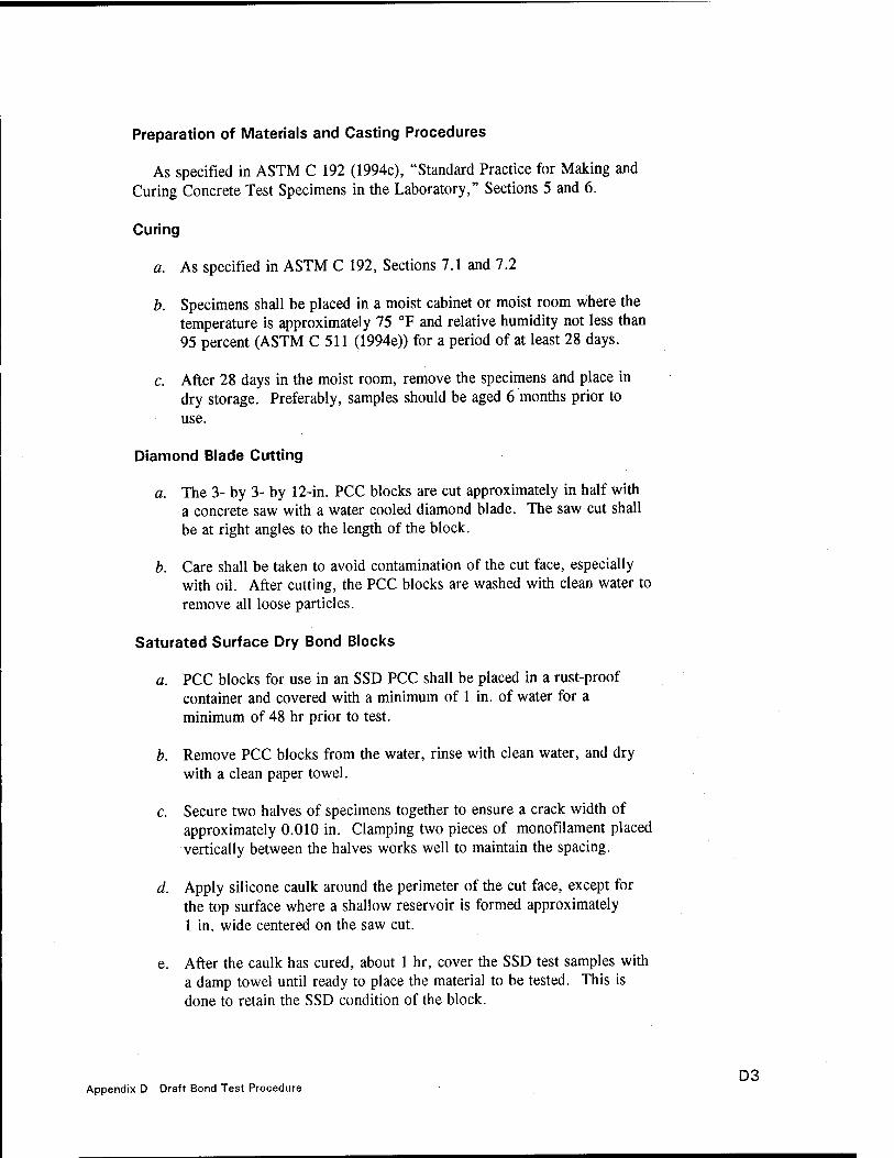
Preparation of Materials and Casting Procedures
As specified in ASTM C 192 (1994c), "Standard Practice for Making and Curing Concrete Test Specimens in the Laboratory," Sections 5 and 6.
Curing
a. As specified in ASTM C 192, Sections 7.1 and 7.2
b. Specimens shall be placed in a moist cabinet or moist room where the temperature is approximately 75 CF and relative humidity not less than 95 percent (ASTM C 511 (1994e)) for a period of at least 28 days.
c. After 28 days in the moist room, remove the specimens and place in dry storage. Preferably, samples should be aged 6 months prior to use.
Diamond Blade Cutting
a. The 3- by 3- by 12-in. PCC blocks are cut approximately in half with a concrete saw with a water cooled diamond blade. The saw cut shall be at right angles to the length of the block.
b. Care shall be taken to avoid contamination of the cut face, especially with oil. After cutting, the PCC blocks are washed with clean water to remove all loose particles.
Saturated Surface Dry Bond Blocks
a. PCC blocks for use in an SSD PCC shall be placed in a rust-proof container and covered with a minimum of 1 in. of water for a minimum of 48 hr prior to test.
b. Remove PCC blocks from the water, rinse with clean water, and dry with a clean paper towel.
c. Secure two halves of specimens together to ensure a crack width of approximately 0.010 in. Clamping two pieces of monofilament placed vertically between the halves works well to maintain the spacing.
d. Apply silicone caulk around the perimeter of the cut face, except for the top surface where a shallow reservoir is formed approximately 1 in. wide centered on the saw cut.
e. After the caulk has cured, about 1 hr, cover the SSD test samples with a damp towel until ready to place the material to be tested. This is done to retain the SSD condition of the block.
Appendix D Draft Bond Test Procedure D3

II —Method of Test to Determine the Bonding Strength
Apparatus
a. Testing machine - The testing machine shall conform to ASTM C 78 (1994b).
b. Apparatus for bonding test.
(1) A diagram of the apparatus and load-applying bar is shown in Figures Dl and D2. The load-applying bar shall provide a uniform point load along the length of the bond interface.
(2) Base Plate. The base plate for this test shall be similar to the one specified in ASTM C 78 with a support length (L) of 9 in.
Fabricating Test Specimens
The test specimens shall be fabricated and cured as specified in Part I. Mix the epoxy in accordance with the manufacturer's recommendations. After complete mixing, immediately fill the reservoir over the saw cut and allow resin to fill the joint. Maintain the reservoir to ensure filling of the joint by gravity. Allow the resin and specimens to cure for 10 days in 70 °F, 50-percent RH unless other cure time or environment is specified. Carefully grind any excess resin from the exterior surfaces prior to testing.
Testing Procedure
All surfaces in contact with the load-applying bar and support block shall be smooth and free of scars, indentations, holes, or inscribed identifications. Turn the test specimen on its side with respect to its position as molded so the top as molded is facing the operator. Center the bond face line on the support block. Center the loading system in relationship to the applied force. Lower the spherical head of the testing machine until there is enough clearance between the spherical head and the test specimen to insert the load-applying bar without tipping over. The load-applying bar shall be placed directly on the bond face line of the specimen.
Apply the load continuously at a rate of 1,500 lb per minute until the specimen breaks. The specimen will break at the bond line, in the PCC, or in the epoxy being tested.
D4 Appendix D Draft Bond Test Procedure

<4
SILICONE- RUBBER
HEAD OF TEST MACHINE
PCC BONDING BLANK
STEEL ROD
LOAD-APPLYING BAR
777/7777, v////////////////////////////////// '/////// -BED OF TESTING MACHINE
STEEL BALL
«s- _L_ 2 2
SPAN LENGTH (L)
Figure D1. Apparatus for bonding strength test in center point loading (Caltrans)
Appendix D Draft Bond Test Procedure D5

11/16* WIDE (4"R ARC CUT-OFF TOP OF RO0(TYP.)
3/4" 0 x 3-1/4* ROD.
■l/2"0 BAU. BEARING
BALL COUNTERSINKO)
-9 3/V-
COUNTERSINK RECESS FOR BALL BEARING(3)
3/8"
BASE PLATE
1/8" R
-M—s BAR FOR "BOND" TEST
NOTE: 1. BALL BEARINGS SILVER SOLDERED TO COUNTER-SINK IN 3/4"0 x 3 1 /4" ROD. 2. RODS CEMENTED TO BASE WITH SILICON RUBBER.
Figure D2. Plan of apparatus for bond test of concrete overlay and patching materials (Caltrans)
D6 Appendix D Draft Bond Test Procedure

Calculations
Calculate the modulus of rupture in bond by dividing the maximum applied load by 2. Report as pounds per square inch.
Report
Since the failure can be bond, PCC, or cohesive failure of the epoxy, it is important to note where the break occurred. If it broke in bond, so note. If it fractured in PCC or cohesive failure of the resin, note approximate percentage of material broken.
The report shall include the following:
a. Identification number and name
b. Curing history
c. Age of test specimens
d. Maximum applied load in pounds
e. Modulus of rupture, to the nearest 5 psi
/ Location of break and percentage
g. Date tested and test operator
h. Defects in specimen, or anything unusual
i. Dry or SSD bond test
Appendix D Draft Bond Test Procedure D7

Appendix E Photographs of Bond Strength Test Specimens
E1 Appendix E Photographs of Bond Strength Test Specimens

ms
•: —IBM—li—I^M«i P^^n^Kia
ättitefiiÄaffiS Lfcsöi*v:' '* * •**i*.*t j
iüiiü'sp WJE NO. 330520-« ?&$}(£#
Sample A Sample B
ÜÖ
Sample C Sample D
Figure E1. Photographs of bond strength test samples after fracture (Sheet 1 of 5)
E2 Appendix E Photographs of Bond Strength Test Specimens

■I
-t-l-rfiNi
SiiiSiliiiitiJiiisifsi
Sample E
m in
Sample F
Sample G
Figure E1. (Sheet 2 of 5)
ÄÄ1
ais??^"s|
Sample H
Appendix E Photographs of Bond Strength Test Specimens E3

WJE NO. 930520-J
Sample J Sample K
l>\- *•» w*\
fe^v.^Äfc?^ih^;.^
Sample L
Figure E1. (Sheet 3 of 5)
Sample N
E4 Appendix E Photographs of Bond Strength Test Specimens

•Swii
Sample 0 Sample M
Figure E1. (Sheet 4 of 5)
Sample R
Appendix E Photographs of Bond Strength Test Specimens E5

Sample S
Sample P
Figure E1. (Sheet 5 of 5)
Sample Q
E6 Appendix E Photographs of Bond Strength Test Specimens
REPORT DOCUMENTATION PAGE Form Approved OMB No. 0704-0188
Public reporting burden for this collection of information is estimated toaverage 1 hour per response, including the time for reviewing instructions, searching existing data sources, gathenng and maintaining the data needed and completing and reviewing the collection of information. Send comments regarding this burden estimate or any other aspect of this collection of information, including suggestions for reducing this burden, to Washington Headquarters Services, Directorate for Information Operations and Reports, 1215 Jefferson Davis Highway, Suite 1204, Arlington, VA 22202-4302, and to the Office of Management and Budget, Paperwork Reduction Project (0704-0188), Washington, DC 20503.
1. AGENCY USE ONLY (Leave blank) REPORT DATE August 1995
3. REPORT TYPE AND DATES COVERED Final report
TITLE AND SUBTITLE Evaluation of Injection Materials for the Repair of Deep Cracks in Concrete Structures
AUTHOR(S) Paul D. Krauss, John M. Scanlon, Margaret A. Hanson
7. PERFORMING ORGANIZATION NAME(S) AND ADDRESS(ES)
Wiss, Janney, Elstner Associates, Inc. 330 Pfingston Road Northbrook, IL 60062-2095
9. SPONSORING/MONITORING AGENCY NAME(S) AND ADDRESS(ES)
U.S. Army Corps of Engineers, Washington, DC 20314-1000; U.S. Army Engineer Waterways Experiment Station, 3909 Halls Ferry Road, Vicksburg, MS 39180-6199
5. FUNDING NUMBERS
Contract No. DACW 39-93-C-0115 Work Unit No. 32636
8. PERFORMING ORGANIZATION REPORT NUMBER
10. SPONSORING/MONITORING AGENCY REPORT NUMBER
Technical Report REMR-CS-48
11. SUPPLEMENTARY NOTES
Available from National Technical Information Service, 5285 Port Royal Road, Springfield, VA 22161.
12a. DISTRIBUTION/AVAILABILITY STATEMENT
Approved for public release; distribution is unlimited.
12b. DISTRIBUTION CODE
13. ABSTRACT (Maximum 200 words)
Wiss, Janney, Elstner Associates, Inc., was requested by the U.S. Army Corps of Engineers to perform a laboratory study to evaluate injection materials for the filling and repair of deep, narrow cracks in massive concrete structures. The emphasis of this study was on epoxies; however, high-molecular-weight methacrylates, ultrafine cements, and polyurethanes were also considered. A laboratory test program was developed to evaluate the properties that are considered to be important for injection materials. These properties included viscosity, surface tension, gel time, penetration, and bond strength to wet concrete. A literature survey and telephone interviews were performed prior to selecting the materials for testing, and a spreadsheet was constructed to aid in choosing the materials to be tested. This report also includes the literature survey and laboratory test data.
The objective of this proposed research is to determine the most promising products (materials), equipment, and procedures available that could most effectively be used to cause the material to most deeply and uniformly penetrate and "heal" existing cracks in massive hydraulic structures.
14. SUBJECT TERMS Crack injection Epoxy resins High-molecular-weight-methacrylate resins
Mass concrete Repair Ultrafine cement
17. SECURITY CLASSIFICATION OF REPORT
UNCLASSIFIED
18. SECURITY CLASSIFICATION OF THIS PAGE UNCLASSIFIED
19. SECURITY CLASSIFICATION OF ABSTRACT
15. NUMBER OF PAGES 102
16. PRICE CODE
20. LIMITATION OF ABSTRACT
NSN 7540-01-280-5500 Standard Form 298 (Rev. 2-89) Prescribed by ANSI Std. Z39-18 298-102