evaluation of heat shields from rts wright ... - sti.srs.gov
TRANSCRIPT

WSRC-TR-2002-00298
Evaluation of Heat Shields from RTS Wright IndustriesMagnesium and Uranium Beds
P.S. Korinko
Materials Technology SectionStrategic Materials Technology Division
Savannah River Technology Center
ISSUED: Aug. 20, 2002
SAVANNAH RIVER TECHNOLOGY CENTER, AIKEN, SC 29808Westinghouse Savannah River CompanyPrepared for the U.S. Department of Energy under Contract DE-AC09-96SR18500

This document was prepared in conjunction with work accomplished under Contract No.DE-AC09-96SR18500 with the U. S. Department of Energy.
DISCLAIMER
This report was prepared as an account of work sponsored by an agency of the United StatesGovernment. Neither the United States Government nor any agency thereof, nor any of theiremployees, makes any warranty, express or implied, or assumes any legal liability or responsibilityfor the accuracy, completeness, or usefulness of any information, apparatus, product or processdisclosed, or represents that its use would not infringe privately owned rights. Reference herein toany specific commercial product, process or service by trade name, trademark, manufacturer, orotherwise does not necessarily constitute or imply its endorsement, recommendation, or favoring bythe United States Government or any agency thereof. The views and opinions of authors expressedherein do not necessarily state or reflect those of the United States Government or any agencythereof.
This report has been reproduced directly from the best available copy.
Available for sale to the public, in paper, from: U.S. Department of Commerce, National TechnicalInformation Service, 5285 Port Royal Road, Springfield, VA 22161,phone: (800) 553-6847,fax: (703) 605-6900email: [email protected] ordering: http://www.ntis.gov/help/index.asp
Available electronically at http://www.osti.gov/bridgeAvailable for a processing fee to U.S. Department of Energy and its contractors, in paper, from: U.S.Department of Energy, Office of Scientific and Technical Information, P.O. Box 62, Oak Ridge, TN37831-0062,phone: (865)576-8401,fax: (865)576-5728email: [email protected]

WSRC-TR-2002-00298 Page iii
Document: WSRC-TR-2002-00298
Title: Evaluation of Heat Shields from RTS Wright IndustriesMagnesium and Uranium Beds
Keywords Mg BedsU BedsRadiant HeatingTEFCoatings
APPROVALS

WSRC-TR-2002-00298 Page iv
List of Figures
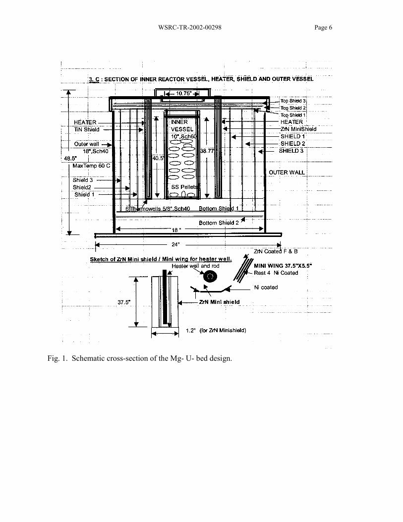
Fig. 1. Schematic cross-section of the Mg- U- bed design. ..................................................6
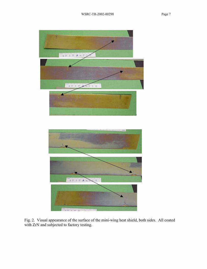
Fig. 2. Visual appearance of the surface of the mini-wing heat shield, both sides. All coatedwith ZrN and subjected to factory testing..............................................................................7
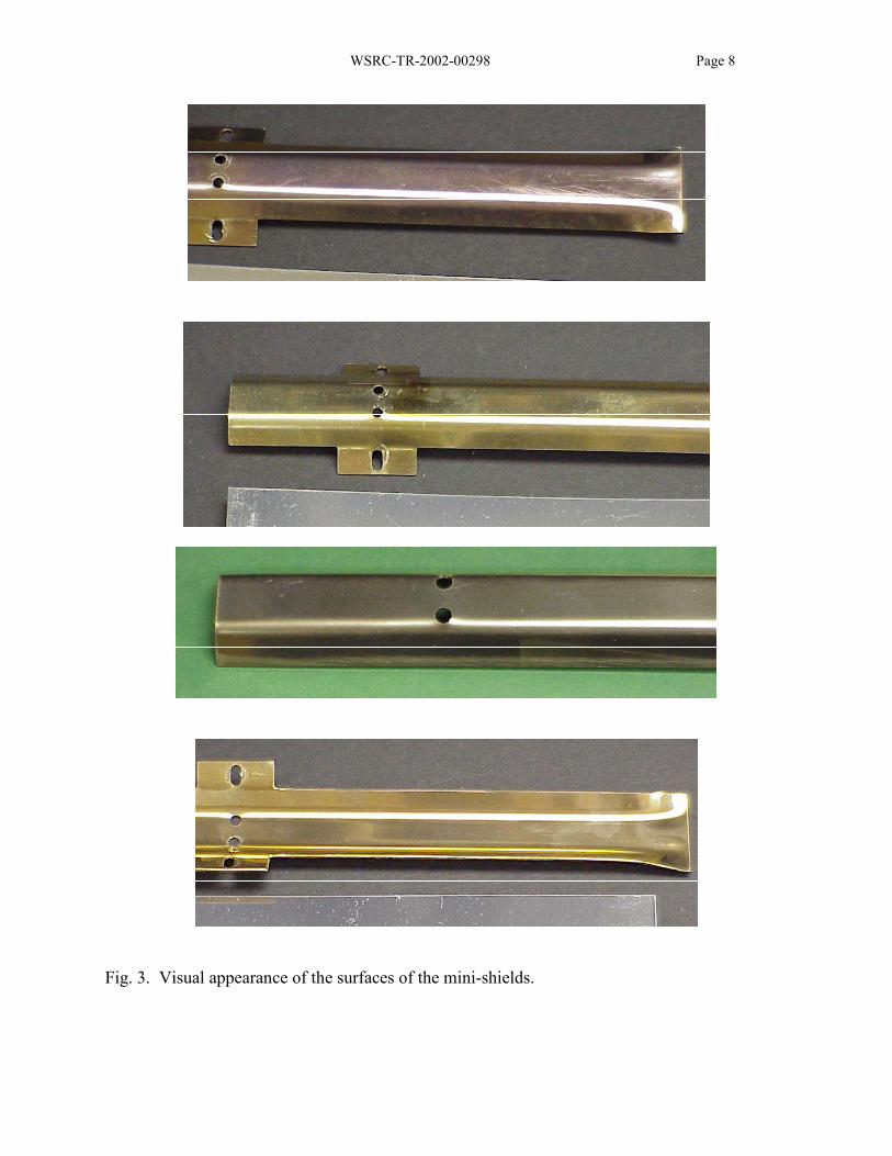
Fig. 3. Visual appearance of the surfaces of the mini-shields. ..............................................8
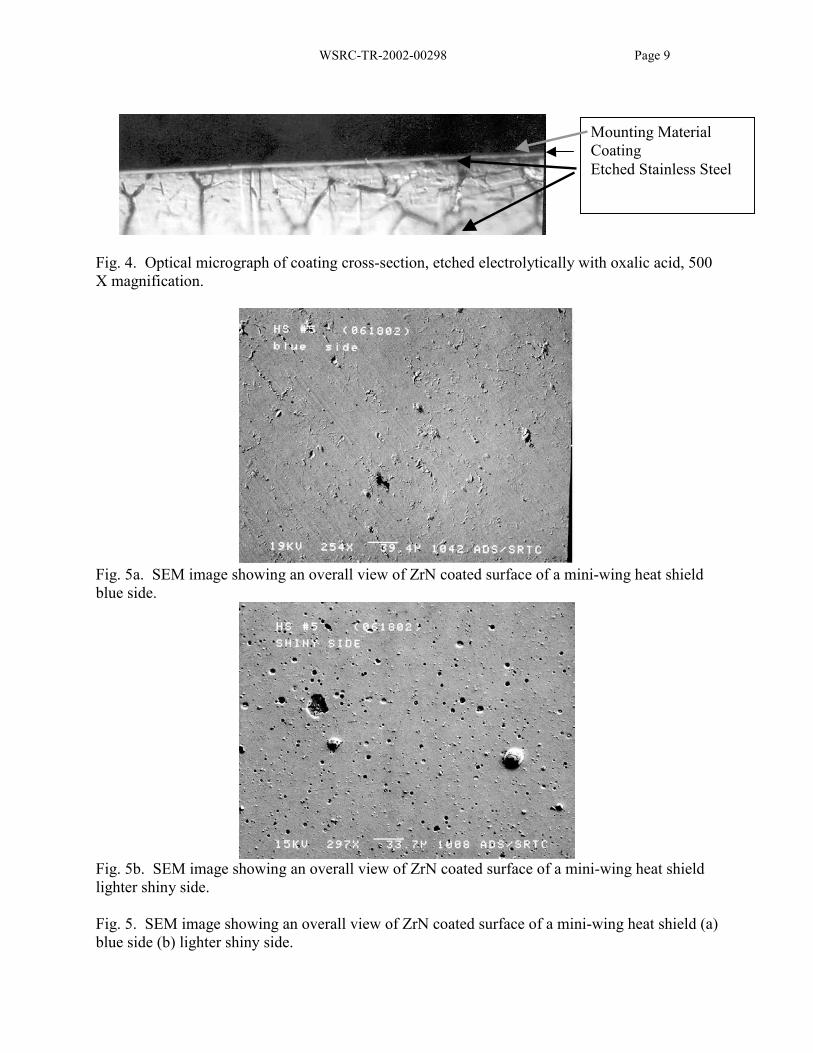
Fig. 4. Optical micrograph of coating cross-section, etched electrolytically with oxalic acid, 500X magnification. ....................................................................................................................9
Fig. 5. SEM image showing an overall view of ZrN coated surface of a mini-wing heat shield (a)blue side (b) lighter shiny side. ..............................................................................................9
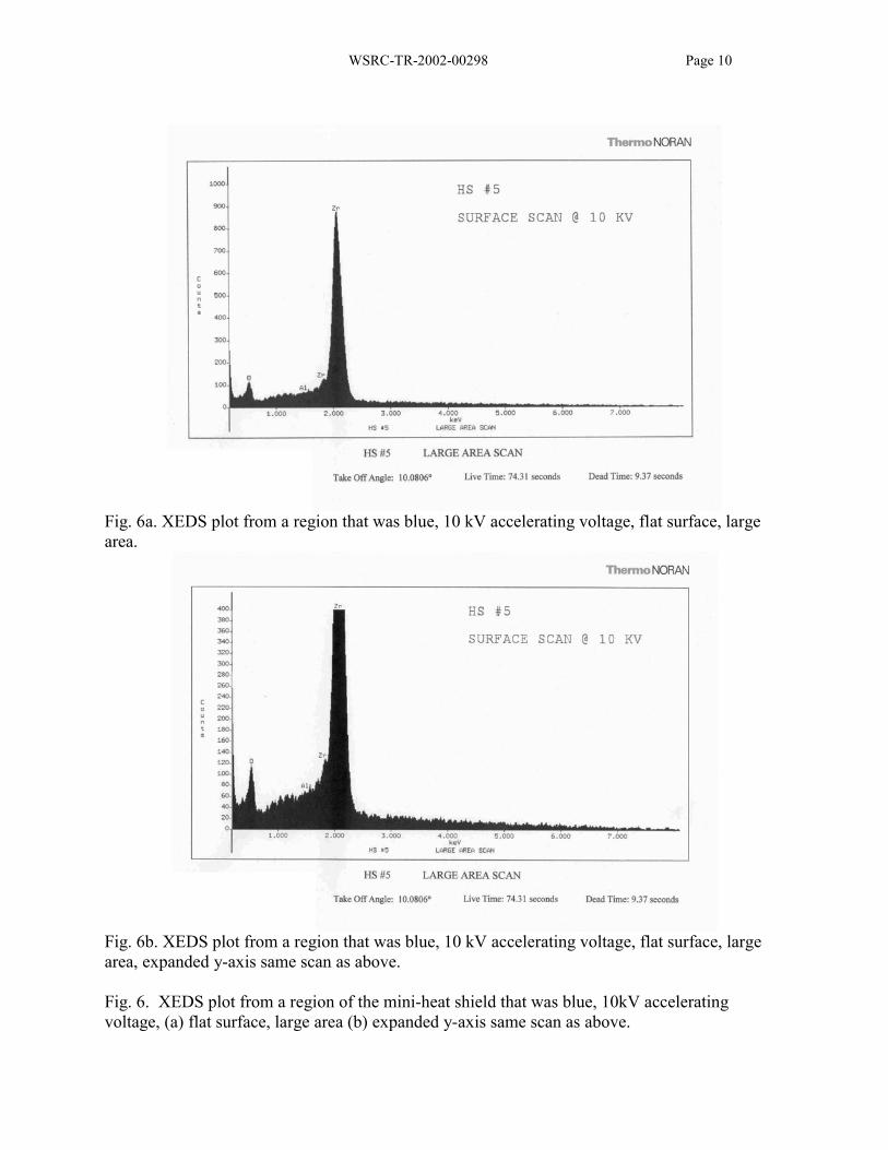
Fig. 6. XEDS plot from a region of the mini-heat shield that was blue, 10kV acceleratingvoltage, (a) flat surface, large area (b) expanded y-axis same scan as above........................10
Fig. 7. XEDS plot from a region of the mini-heat shield that was gold, 15kV acceleratingvoltage, (a) flat surface, large area (b) expanded y-axis same scan as above........................12
Fig. 8. XEDS plot from a region of the mini-heat shield that was gold, 10kV acceleratingvoltage, (a) flat surface, large area (b) expanded y-axis same scan as above........................12
Fig. 9. XEDS plot from a region of the mini-heat shield that was gold, 15kV acceleratingvoltage, (a) flat surface, large area (b) expanded y-axis same scan as above........................13
Fig. 10. SEM micrograph of surface of ZrN coated sample that exhibited a (a) near metallicwhite sheen (b) near metallic white sheen and (c) a blue oxide film. XEDS data for each spotare shown in Figure 11...........................................................................................................14
Fig. 11. XEDS plots of spots shown in Fig. 10, (a) spot 1, (b) spot 2, (c) spot 3, (d) spot 4, (e)spot 5, and (f) spot 6. .............................................................................................................15-17
Fig. 12. AES composition profile of ZrN coated heat shield that exhibited (a) gold coloration (b)blue coloration. ......................................................................................................................18-19
Fig. 13. AES composition profile from gold mini-heat shield (a) oxide to nitride transition (b)nitride to base metal transition. ..............................................................................................20-21
Fig. 14. AES composition profile from blue mini-heat shield (a) oxide to nitride transition (b)nitride to base metal transition. ..............................................................................................22-23
WSRC-TR-2002-00298 Page 1
Evaluation of Heat Shields from RTS Wright IndustriesMagnesium and Uranium Beds
P.S. Korinko
SUMMARY
Heat shields from a factory test of the furnaces that will be used to heat the magnesium anduranium beds for the tritium extraction facility (TEF) were examined to determine the cause ofdiscoloration. The samples were examined using visual, optical microscopy, electronmicroscopy, x-ray spectroscopy, and Auger electron spectroscopy. The coating had the expectedsurface related growth anomalies. The surface discoloration was caused by oxidation. Therewas also evidence of minor aluminum contamination. It is expected that the heat shields willcontinue to degrade and ultimately result in a gray-body emissivity of about 0.5. This willadversely affect the radiant heat transfer to the vessel. A low emissivity noble metal or alloycoating or monolith is recommended as an alternate first shield material.
BACKGROUND
RTS Wright Industries (Wright) is fabricating new magnesium and uranium bed heaters for thetritium extraction facility (TEF). These beds are designed with a permeation barrier coating onboth the internal and external surfaces of the inner vessel (cartridge). The inner vessel is heatedusing radiant heating, heating elements are backed by radiant heat transfer shields of polishedstainless steel coated with a reflective coating, see Fig. 1. Numerous coatings were tested,including titanium nitride, zirconium nitride and electroless nickel. There are three (3) heatshields in each heat shield pack. During operation, the annular space is evacuated to a vacuumon the order of 100 mTorr. In order to test the system, the retort was heated to 600°C using theradiant heater design. This design is different from previous designs that had significantly moreheater elements. The intent of this new heating system is to reduce the heat load to the glovebox.
Several tests were conducted using the various coated heat shields. In all cases, the originallyshiny shields were discolored. The surfaces remained reflective but exhibited heat tints thatranged from golden to purple. It is anticipated that additional exposure to the annular vacuumconditions will result in a surface that is no longer as reflective. This increase in emissivity willlikely reduce the thermal efficiency of the heater and subsequently increase the heat load into theglove box and may preclude the inner vessel from reaching its required operating temperature. Ifthis occurs, additional operating expenses will be encountered by the TEF due to removal andreplacement of magnesium and uranium beds and heaters. A ZrN coated heat shield, and twomini-heat shields were submitted to the Materials Compatibility and Joining Technology Group(MCJTG) for evaluation.

WSRC-TR-2002-00298 Page 2
EVALUATION METHODS
The ZrN coated samples were visually examined to determine the variation in color.
Optical microscopy was used to examine cross-sections of the coating and surface discoloration.Surface roughness and the presence of voids and coating defects were also examined.
Scanning electron microscopy (SEM) analysis was used to determine surface topography,estimate coating thickness and provide gross chemical analysis of the surface. The SEMmicrochemistry results were obtained using x-ray energy dispersive spectroscopy (XEDS).
Auger electron spectroscopy (AES) was used to determine the surface chemistry. Scanningelectron images and backscatter electron images of the sputtered areas were also obtained.
RESULTS
Visual examination of the heat shield revealed discoloration that ranged from dark gold topurple. The surfaces retained a “glossy” appearance despite the discoloration. Opticalphotographs of the surface are shown in Figs. 2 and 3, of the mini-wing and mini-shield,respectively. These photographs exhibit color variations, the large heat shield exhibits a darkgold to dark blue coloration. The variation from end to end is a consequence of the temperaturevariation within the furnace.
Metallographic examination of the coating cross-section did not reveal evidence of surfaceattack. The cross-section revealed a compact coating with a few expected growth defects, Fig. 4.
Scanning electron microscopy of the coating surface revealed crater-like defects, Fig. 5. Thesedefects are likely due to surface burnishing, either as a matter of post-coating processing orsimple handling. The surface exhibits these craters and some positive coating defects. Thepositive defects are typically caused by a subsurface anomaly that disrupts the growthmorphology. The side of the mini-wing heat shield that was exposed to the heater element didnot exhibit as many positive-coating anomalies as the backside.
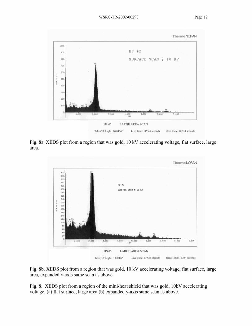
X-ray energy dispersive spectroscopy on the surfaces of the heat shields revealed that the ZrNcoating was sufficiently thin to have the substrate interfere with the surface analysis. The largestpeak is due to zirconium. The substrate elements of iron, chromium and nickel that weredetected had peak heights that were dependent on the accelerating voltage and the coatingthickness, compare Fig. 6a to Fig. 7a and Fig. 8a to Fig. 9a. This condition would not be anissue, except that the Cr-Lβ1 interferes with the oxygen peak, which confounds the data andmakes resolution difficult where the oxide layer is thin, as in the gold discolored heat shieldXEDS scan shown in Fig. 9b. At relatively low accelerating voltages, however, the interactionvolume is reduced so the coating substrate interactions are minimized. Oxygen is clearly visiblein the blue discolored heat shield sample, Fig. 6 and less visible in the gold discolored sample,Fig. 8. The vendor had speculated that the discoloration was due to aluminum migration, soaluminum was specifically examined. An aluminum peak is identified, however, it is just above
WSRC-TR-2002-00298 Page 3
the background. It is suspected that the detection of aluminum may be due to its presence as partof the SEM fixtures rather than being present on the surface of the sample.
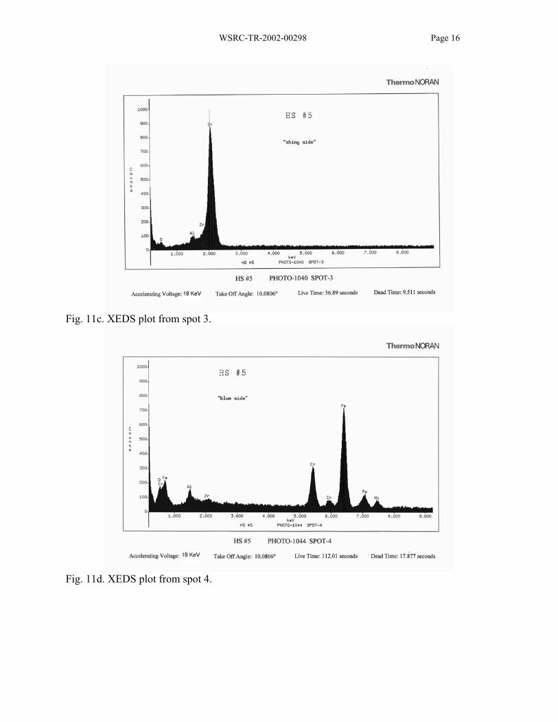
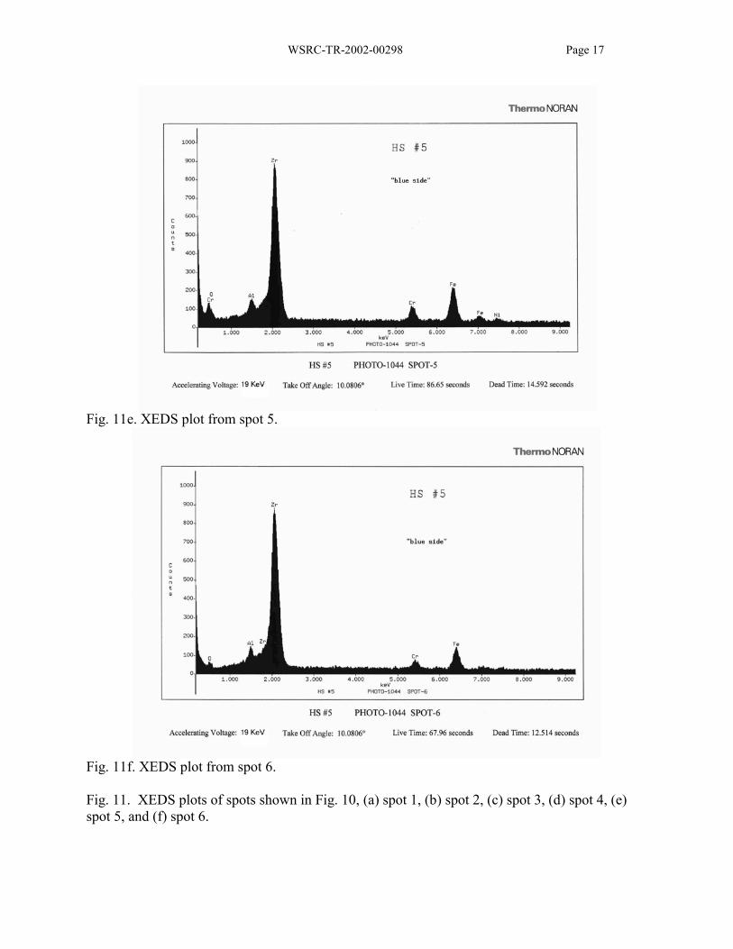
In addition, the surface condition that exhibited features of interest was analyzed. The electronimages of the surfaces that were shiny and blue are shown in Fig. 10. The different spots aremarked 1 - 6 with the XEDS results in Figs. 11a - 11f. The depressions in Figs. 10a and 10c,spots 1 and 4, exhibit little or no zirconium, only zirconium was detected at spots 2 and 3, whilea mixture of zirconium and stainless steel were detected at spots 5 and 6. Aluminum is identifiedon these XEDS plots, but no explanation is obvious.
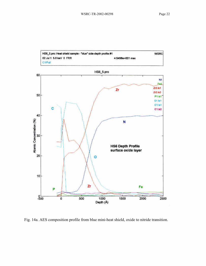
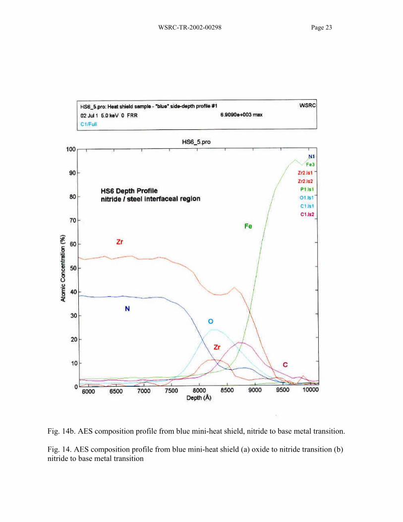
Auger electron spectroscopy is a powerful surface analysis and coating evaluation technique.Using AES the elements, and in some cases the valence state, present from about 50 angstroms(Å) to 25,000 Å (1 Å = 0.1 nm) were determined. A preliminary scan did not support the XEDSnear surface contamination due to aluminum, even though aluminum was specifically sought.The only contaminant detected was oxygen as shown in Figs. 12a and 12b, and Figs. 13a and14a. The near surface data for the zirconium peak exhibited a shift in energy due to a valence offour vs. two for the oxide and nitride phases, respectively which can be seen in Figs. 13a and14a. The thickness of the oxide layer was about 400 Å for the gold discolored surface, Figs. 12aand 13a and 900 Å for the blue discolored surface, Figs. 12b and 14a.
The depth profile of selected elements for both the blue and gold heat tinted heat shield areas areshown in Fig. 12. Only zirconium and nitrogen are detected through the bulk of the coating.The aluminum scan is in the same level as the noise, which suggests that it, is not present inadequate quantities to be considered. Carbon is present at the surface, Figs. 13a and 14a, and is avery common surface contaminant detected by AES. Depth profiles exhibit a transition at thesurface from zirconium and oxygen to zirconium and nitrogen beyond the oxide transition depth.
Another interesting result that was observed was that several of the samples that were examinedexhibited the opposite transition, i.e., that of ZrN to ZrO2, at the metal coating interface. This isapparent from the data presented in Figs. 12a, 12b, and 14b, while not all of the samplesexhibited this transition, Fig. 13b, although these data indicate an increase in carbon content nearthe surface. The cause of these variations was not determined.
DISCUSSION AND CONCLUSIONS
The surface discoloration is caused primarily by oxidation. A review of the vendor test reportindicates that many of the appropriate steps were taken to minimize oxygen ingress. Themultiple evacuate and backfill procedure should have helped prevent significant oxidation.Unfortunately, a leak rate test was not conducted. This data would help define the best practicefor resolution of the oxidation issue. In addition, this testing was conducted using continuouspumping and vacuum significantly better than what is expected for the production TEF heaterbeds.
Aluminum contamination on the surface of the discolored heat shield was detected based on theSEM XEDS results but not confirmed with AES. The AES is a more sensitive instrument todetect surface contamination than the SEM using XEDS. It is suspected that the aluminum is an
WSRC-TR-2002-00298 Page 4
artifact of the analysis technique rather than actually being present as a contaminant. Thespeculation that the discoloration was caused by aluminum vaporization is difficult to concurwith since the partial pressure of aluminum at 600°C is expected to be less than 10-10 atm (7.6 x10⁻⁸ torr). Thus, there is a significant backpressure to minimize aluminum vaporization.Aluminum vaporization in vacuum systems can be significant at higher temperatures.
Additional testing which might be possibly used to determine the extent of oxygencontamination in the annulus would include evacuating and heating the chamber to determine thegaseous species being evolved and determining the gas composition using a mass spectrometer.Aluminum would likely not be detected using this method since it would condense on the coolsurfaces of the detector.
Virtually any material that forms a tenacious, oxide scale will discolor under the conditions thathave been tested, 600°C and pressure of 50 mTorr. In order to avoid changing the spectralreflectance of the surface, a lower oxygen pressure needs to be established or a “non-scaling”noble metal must be used. The operating temperature of the bed is nominally 475°C. Thistemperature is needed to ensure rapid enough reaction rates and efficiency. Since the watercracking is a thermally driven process, a change in temperature of 15°C will typically result in achange of reaction rate of a factor of two (general rule of thumb for Arrehenius reactions).
It is expected that the surface oxidation of the heat shields will continue, especially since theTEF will use a passive vacuum system. The emissivity is expected to increase. This willdecrease the radiant heat transfer into the inner vessel, (cartridge). This degradation will likelyincrease the power requirements for the heaters and result in increased outer vessel temperatures.
RECOMMENDATIONS
Testing:
• Measure the leak rate of the outer vacuum chamber; the testing with continuous evacuationof the annulus does not duplicate the anticipated TEF operating conditions.
• Determine gas species present during operation using mass spectrometry.
• Decrease test temperature. The operating temperature for the beds is about 475°C. A testtemperature of 530°C provides a 50°C over-temperature condition, thus lowering it beyondthis is not feasible.
Fabrication:
• Utilize a more noble coating or substrate for the first shield. Two materials that will likelywork well are gold or platinum plating or thin sheets. The use of gold-nickel braze alloy atthis temperature has been reported (ASM Metals Handbook, Volume 6, Brazing, Solderingand Welding, Ninth Edition). There are three possible degradation modes, interdiffusion ofthe plated element into the stainless steel surface which would reduce the emissivity, gold orplatinum oxide vaporization and the loss of the coating, and coating grain growth with

WSRC-TR-2002-00298 Page 5
subsequent coating breaches and substrate oxidation. Recent searches have revealed analuminum based low emissivity coating that may also be useful.
• Incorporate a getter material into the cartridge surface. This addition could be made byadding a sheet of oxygen getter material to the side or bottom of the Mg / U cartridge. Itwould decrease the oxygen partial pressure to a value significantly lower than that achievableby mechanical vacuum systems.
• Polish the inner wall of the outer vessel to decrease its emissivity. This change may helpreduce the outer wall temperature by increasing the thermal reflective surfaces.
• Increase the emissivity of the outer wall of the inner vessel. This can be accomplished by“blackening” the surface or by roughening it. The surface could be “blackened” using athermal oxidation treatment. Both grit blasting or oxidation of the surface may promoteoxygen adsorption and cause increased heat shield oxidation.
• Improve the vacuum to high vacuum values with minimal external gas ingress. Use a turbo-pump or the like to ensure a vacuum of 10-5 torr. This will decrease the oxidation ratesomewhat, but an oxide film is still possible.
• Eliminate the outer aluminide coating on the Mg bed cartridge. This coating surface is notperfectly smooth and offers areas for oxygen to adsorb. The desorbing oxygen acts as avirtual source for subsequent oxidation.
ACKNOWLEDGEMENTS
The author would like to thank the TEF project for supporting this evaluation. He would alsolike to thank Zane Nelson and Cindy Foreman for metallographic support. The efforts of JackDurden for SEM and XEDS work are also appreciated. Finally, the author would like toacknowledge the efforts and support of Don Blankenship for the Auger electron spectroscopy.
WSRC-TR-2002-00298 Page 6
Fig. 1. Schematic cross-section of the Mg- U- bed design.
WSRC-TR-2002-00298 Page 7
Fig. 2. Visual appearance of the surface of the mini-wing heat shield, both sides. All coatedwith ZrN and subjected to factory testing.
WSRC-TR-2002-00298 Page 8
Fig. 3. Visual appearance of the surfaces of the mini-shields.
WSRC-TR-2002-00298 Page 9
Fig. 4. Optical micrograph of coating cross-section, etched electrolytically with oxalic acid, 500X magnification.
Fig. 5a. SEM image showing an overall view of ZrN coated surface of a mini-wing heat shieldblue side.
Fig. 5b. SEM image showing an overall view of ZrN coated surface of a mini-wing heat shieldlighter shiny side.
Fig. 5. SEM image showing an overall view of ZrN coated surface of a mini-wing heat shield (a)blue side (b) lighter shiny side.
Mounting MaterialCoatingEtched Stainless Steel
WSRC-TR-2002-00298 Page 10
Fig. 6a. XEDS plot from a region that was blue, 10 kV accelerating voltage, flat surface, largearea.
Fig. 6b. XEDS plot from a region that was blue, 10 kV accelerating voltage, flat surface, largearea, expanded y-axis same scan as above.
Fig. 6. XEDS plot from a region of the mini-heat shield that was blue, 10kV acceleratingvoltage, (a) flat surface, large area (b) expanded y-axis same scan as above.

WSRC-TR-2002-00298 Page 11
Fig. 7a. XEDS plot from a region that was blue, 15 kV accelerating voltage, flat surface, largearea.
Fig. 7b. XEDS plot from a region that was blue, 15 kV accelerating voltage, flat surface, largearea, expanded y-axis same scan as above.
Fig. 7. XEDS plot from a region of the mini-heat shield that was gold, 15kV acceleratingvoltage, (a) flat surface, large area (b) expanded y-axis same scan as above.
WSRC-TR-2002-00298 Page 12
Fig. 8a. XEDS plot from a region that was gold, 10 kV accelerating voltage, flat surface, largearea.
Fig. 8b. XEDS plot from a region that was gold, 10 kV accelerating voltage, flat surface, largearea, expanded y-axis same scan as above.
Fig. 8. XEDS plot from a region of the mini-heat shield that was gold, 10kV acceleratingvoltage, (a) flat surface, large area (b) expanded y-axis same scan as above.

WSRC-TR-2002-00298 Page 13
Fig. 9a. XEDS plot from a region that was gold, 15 kV accelerating voltage, flat surface, largearea.
Fig. 9b. XEDS plot from a region that was gold, 15 kV accelerating voltage, flat surface, largearea, expanded y-axis same scan as above.
Fig. 9. XEDS plot from a region of the mini-heat shield that was gold, 15kV acceleratingvoltage, (a) flat surface, large area (b) expanded y-axis same scan as above.

WSRC-TR-2002-00298 Page 14
Fig 10a. SEM image of surface of ZrN coated sample that exhibited a near metallic white sheen
Fig 10b. SEM image of surface of ZrN coated sample that exhibited a near metallic white sheen
Fig 10c. SEM image of surface of ZrN coated sample that exhibited a blue oxide film.
Fig. 10. SEM micrograph of surface of ZrN coated sample that exhibited a (a) near metallicwhite sheen (b) near metallic white sheen and (c) a blue oxide film. XEDS data for each spotare shown in Figure 11.
Spot 2Fig. 11b
Spot 1 Fig. 11a
Spot 3Fig. 11c
Spot 4, Fig. 11d Spot 5, Fig. 11e
Spot 6Fig. 11f

WSRC-TR-2002-00298 Page 15
Fig. 11a. XEDS plot from spot 1.
Fig. 11b. XEDS plot from spot 2
WSRC-TR-2002-00298 Page 16
Fig. 11c. XEDS plot from spot 3.
Fig. 11d. XEDS plot from spot 4.
WSRC-TR-2002-00298 Page 17
Fig. 11e. XEDS plot from spot 5.
Fig. 11f. XEDS plot from spot 6.
Fig. 11. XEDS plots of spots shown in Fig. 10, (a) spot 1, (b) spot 2, (c) spot 3, (d) spot 4, (e)spot 5, and (f) spot 6.

WSRC-TR-2002-00298 Page 18
Fig. 12a. AES composition profile of ZrN coated mini-heat shield that exhibited gold coloration.

WSRC-TR-2002-00298 Page 19
Fig. 12b. AES composition profile of ZrN coated mini-heat shield that exhibited blue coloration.
Fig. 12. AES composition profile of ZrN coated heat shield that exhibited (a) gold coloration (b)blue coloration.

WSRC-TR-2002-00298 Page 20
Fig. 13a. AES composition profile from gold mini-heat shield, oxide to nitride transition.

WSRC-TR-2002-00298 Page 21
Fig. 13b. AES composition profile from gold mini-heat shield, nitride to base metal transition.
Fig. 13. AES composition profile from gold mini-heat shield (a) oxide to nitride transition (b)nitride to base metal transition.
WSRC-TR-2002-00298 Page 22
Fig. 14a. AES composition profile from blue mini-heat shield, oxide to nitride transition.
WSRC-TR-2002-00298 Page 23
Fig. 14b. AES composition profile from blue mini-heat shield, nitride to base metal transition.
Fig. 14. AES composition profile from blue mini-heat shield (a) oxide to nitride transition (b)nitride to base metal transition