evaluating and improving the seismic performance …399316/plse2015_4_mahin... · evaluating and...
TRANSCRIPT
EVALUATING AND IMPROVING THE SEISMIC PERFORMANCE OF OLDER TALL BUILDINGS
Stephen Mahin1*, Juin Wei Lai2, Shanshan Wang1 and Matthew Schoettler1 1 Pacific Earthquake Engineering Research Center,
777 Davis Hall, University of California, Berkeley, CA 94720-1710 *[email protected] 2 Degenkolb Engineers, 1300 Clay Street, Oakland, CA 94612
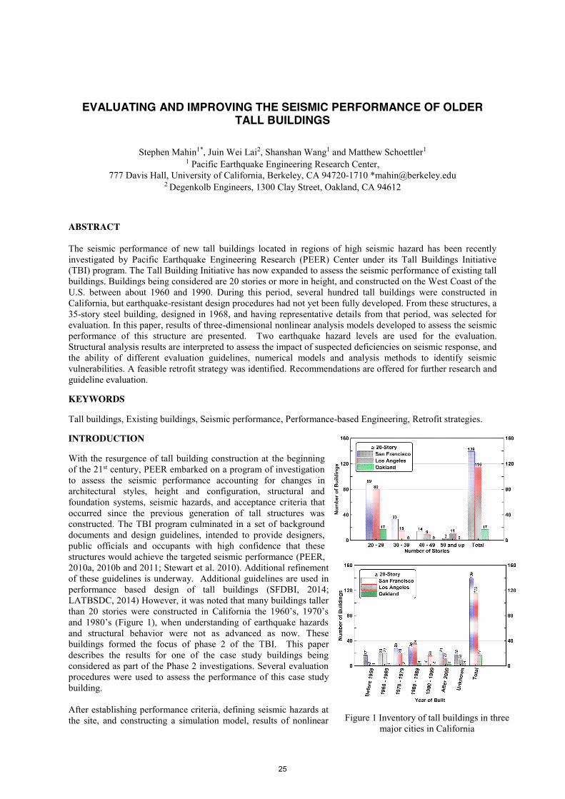
ABSTRACT The seismic performance of new tall buildings located in regions of high seismic hazard has been recently investigated by Pacific Earthquake Engineering Research (PEER) Center under its Tall Buildings Initiative (TBI) program. The Tall Building Initiative has now expanded to assess the seismic performance of existing tall buildings. Buildings being considered are 20 stories or more in height, and constructed on the West Coast of the U.S. between about 1960 and 1990. During this period, several hundred tall buildings were constructed in California, but earthquake-resistant design procedures had not yet been fully developed. From these structures, a 35-story steel building, designed in 1968, and having representative details from that period, was selected for evaluation. In this paper, results of three-dimensional nonlinear analysis models developed to assess the seismic performance of this structure are presented. Two earthquake hazard levels are used for the evaluation. Structural analysis results are interpreted to assess the impact of suspected deficiencies on seismic response, and the ability of different evaluation guidelines, numerical models and analysis methods to identify seismic vulnerabilities. A feasible retrofit strategy was identified. Recommendations are offered for further research and guideline evaluation. KEYWORDS Tall buildings, Existing buildings, Seismic performance, Performance-based Engineering, Retrofit strategies. INTRODUCTION With the resurgence of tall building construction at the beginning of the 21st century, PEER embarked on a program of investigation to assess the seismic performance accounting for changes in architectural styles, height and configuration, structural and foundation systems, seismic hazards, and acceptance criteria that occurred since the previous generation of tall structures was constructed. The TBI program culminated in a set of background documents and design guidelines, intended to provide designers, public officials and occupants with high confidence that these structures would achieve the targeted seismic performance (PEER, 2010a, 2010b and 2011; Stewart et al. 2010). Additional refinement of these guidelines is underway. Additional guidelines are used in performance based design of tall buildings (SFDBI, 2014; LATBSDC, 2014) However, it was noted that many buildings taller than 20 stories were constructed in California the 1960’s, 1970’s and 1980’s (Figure 1), when understanding of earthquake hazards and structural behavior were not as advanced as now. These buildings formed the focus of phase 2 of the TBI. This paper describes the results for one of the case study buildings being considered as part of the Phase 2 investigations. Several evaluation procedures were used to assess the performance of this case study building. After establishing performance criteria, defining seismic hazards at the site, and constructing a simulation model, results of nonlinear Figure 1 Inventory of tall buildings in three
major cities in California
25
time history analyses are presented for two seismic hazard levels. These analyses identify significant potential structural deficiencies at the higher hazard level. As a result, several potential retrofit strategies are identified. Results for several alternative retrofits based on the use of fluid viscous dampers (FVD) are examined. Additional research and guideline refinement and validation are recommended to reduce the uncertainty with regards to modeling and analyzing existing tall buildings, and to establish appropriate design criteria. More detailed information about the study reported herein can be found in Lai et al. 2015. EVALUATION OF EXISTING TALL BUILDINGS Many tall buildings have performed satisfactorily during moderate to strong ground shaking. In some parts of the world, such as the West Coast of the U.S., numerous tall buildings were designed and constructed when building codes were not as advanced as now. A casual inspection of actual buildings, and codes used prior to about 1990, indicate that for the western U.S. many tall buildings have features vulnerable to strong earthquake excitation. Problematic geometric features include vertical irregularities, especially at the base of the building where partial mezzanines, tall first story columns (compared to typical story heights), discontinuous columns, sudden changes in framing systems, etc. Similarly, challenges arise due to irregularities in plan, such as when L, T or other floor layouts are used or when elements of the lateral load resisting system are asymmetrically placed in the structure. While engineering methods exist today to address some of these issues, and some of the features may be proscribed, this was not the case two or more decades ago. Similarly, many of these buildings were designed for lateral design forces much smaller than used today, and many were not designed to limit lateral drifts due to seismic excitations. For steel moment frame buildings, a very common form of early high-rise construction in the Western U.S., building codes for these early designs did not require columns to be stronger than the adjacent beams, beam-column panel zones were not required to develop the capacity of the members framing into them, and pre-Northridge connections were used to attach the beams to the columns. Capacity design concepts were not used during the period of interest here, so that plastic hinge yielding may not dominate inelastic response. Moreover, the low design lateral forces, the low use of dynamic analysis methods, and the absence of capacity design concepts resulted in column splices that are not able to develop the capacity of the members being attached. Thus, there are many features of older steel (and other) tall buildings that raise concern. The vulnerability of older welded steel moment-resisting frame structures was addressed as part of the SAC Steel Project following the 1994 Northridge earthquake. The State-of-the-Art Report on Performance Prediction and Evaluation of Steel Moment-Frame Structures (FEMA 355F (FEMA 2000)) examined the behavior of 3, 9 and 20 story welded steel moment frame structures designed according to different codes. For the case of a 20-story building designed in the Los Angeles Area according to the 1973 Uniform Building Code (ICBO 1973), the confidence that the collapse prevention limit state can be achieved for maximum considered level excitations is less than 50%. Moreover, there is more than a 70% confidence that at least one beam column connection will exceed its deformation capacity and fracture in a brittle manner. Even for similar designs based on the 1994 Uniform Building Code (ICBO 1994), FEMA 355F suggests that there is more than an 80% probability of seeing brittle connection fractures. However, the imposition of a strong column-weak girder design philosophy in that code increases the confidence of avoiding global collapse to about 75%. Similar findings were obtained by others (e.g. Krishnan and Muto 2011).
The seismic performance evaluation presented in this paper follows ASCE 41-13, “Seismic Evaluation and Retrofit of Existing Buildings” (ASCE 2013). ASCE 41 has been adopted by the California Building Code (CBSC 2013) for seismic rehabilitation of existing buildings. Performance objectives for the building are selected to conform to the Basic Performance Objective for Existing Buildings (BPOE) described in ASCE 41. ASCE 41 outlines a three-tiered approach to evaluation. For a complex high-rise structure, like the case study building, the ASCE 41 Tier 1 simplified screening evaluation is not required. Instead, the Tier 3 systematic evaluation procedure is automatically required. However, to identify potential seismic deficiencies, the Tier 1 screening evaluation was performed. Tier 2 “deficiency-based” procedure was also not required, and is not included herein as part of the evaluation. Thus, the principal seismic performance evaluation utilizes the Tier 3, dynamic analysis approach. These analyses were based on the available existing as-built drawings and engineering judgment regarding the likely behaviour of pre-Northridge era steel construction. Nonetheless, the Tier 1 procedure was used to identify deficiencies in the structural system. This tier utilizes checklists to evaluate the adequacy of a building’s lateral force-resisting system. The “Basic Configuration Checklist”, which is applicable to all building types, was followed. ASCE 41 also has additional checklists for both Life Safety (LS) and Immediate Occupancy (IO) performance levels. The basic performance objective for
26

existing building (BPOE) recommended by ASCE 41 requires the prototype building to meet the Life Safety (S-3) performance level. Therefore, the Checklists for the Life Safety performance level were also completed. For a more complete evaluation, considering the cost of repair, downtime, business interruption costs associated with disruption or loss of occupancy, see Porter (2009), FEMA (2012) and Terzic et al. (2015).
THE CASE STUDY BUILDING The existing building considered in this paper is a 35-story tall (about 490-ft in height), approximately 185 ft. by 135 ft. in plan (Figure 2). It was built in San Francisco starting in 1968. The typical story height is 13-ft. The building is constructed over three basement levels. The structural system consists of complete, three-dimensional, welded steel, moment-resisting space frames. These steel frames consist primarily of built-up box (single-cell or two-cell) or wide flange columns welded to beams (either built-up or hot-rolled sections). A typical 6-in.-thick concrete slab on metal deck is provided at each floor. The perimeter precast concrete façade and other non-structural elements were not simulated in the analytical model. The building’s foundation consists of a 7-ft-thick foundation mat located 40-ft below grade and supported by more than 2,500 concrete piles that extended to 60-ft below the mat. The foundation mat is connected to a 3-ft-thick retaining wall running around the entire site. Member sizes, structural detail drawings, foundation details and other information were collected from the building owner and the department of building inspection, San Francisco (DBI 2013). Beam-to-column moment connections incorporate typical pre-Northridge details. Partial joint penetration (PJP) weld column splice details are used. Based on research following the Northridge earthquake, these types of connections are expected to be relatively brittle. Column slices use partial penetration welds, located about 4 ft. from the lower floor level, and these are relatively brittle if overloaded. Performance objectives and ground motion selection The Basic Performance Objectives (BPOE) in ASCE 41 depend on the risk category (occupancy) of the building and the evaluation procedure used. Here, the risk category of the prototype building was selected to be III, based on ASCE 7-10 (ASCE 2010). The BPOE criteria for structural elements are “Damage Control” at the BSE-1E seismic hazard level (20% probability of exceedence in 50 years; 225 year mean return interval), and “Limited Safety” at the BSE-2E level (5% probability of exceedence in 50 years; 975 year return interval). Numerous sets of ground motions were developed based on various code requirements and probability of exceedence levels (Baker 2014). Each set consisted of 20 three-component records. Ground motions were extracted from the PEER NGA West2 database, and no more than five ground motions were taken from any single event. For this paper, results for two different hazard levels, BSE-1E and BSE-2E, are presented Ground motions were scaled so the square root sum of square (SRSS) of their two horizontal response spectrum matched the associated target spectrum between 0.5 and 10 seconds for each hazard level. Ground motions were selected such that the distance to rupture was less than 50 km, the magnitude of event was 6.5 or larger, and the scale factor needed was less than 9. Figure 3 shows the horizontal response spectra of the ground motions for the BSE-1E and BSE-2E hazard levels.
a. BSE-2E hazard level b. BSE-1E hazard level Figure 3 Response spectra of selected ground motion records and target spectra
Figure 2 Perspective View of Case Study
Building
27

Mathematical Modeling A three-dimensional computer model was constructed in OpenSees (McKenna and Fenves 2010). All above ground main framing members contributing to the seismic lateral force resisting systems are included in the model (see Figure 2). A fixed-base boundary condition is used at the column bases at the ground level. Concrete floor slabs are not included in the numerical model, but rigid in-plane diaphragm constraints are introduced. Dead loads and 25% of design live loads are included in the seismic analyses. The first three elastic modal periods of the structure are: 4.33 s (x-translation), 4.18 s (y-translation), and 3.58 s (rotation about the z-axis). Columns are modeled using displacement-based nonlinear beam-column elements with fiber sections at five integration points along the length of element. Each fiber section has 4 layers in the width (or depth) direction and 4 layers in the thickness direction of any part of a section. A Giuffré-Menegotto-Pinto material model with isotropic strain hardening (Steel02) is used to define the fiber sections. Structural materials are modeled per ASCE 41, Section 9.2.2. The expected steel material strength is estimated as the multiplication of lower bound strength and modification factor for each material class. Column splices are modeled and assumed to be either fully ductile (no failure) or brittle. To capture the brittle behavior, a maximum permitted tension fiber strain for each column splice location is derived and assigned to the corresponding fiber section within the zerolengthsection element (Kanvinde 2012). Beams are modeled using force-based nonlinear beam-column elements with finite-length plastic hinges at both ends as proposed by Ribeiro et al. (Ribeiro 2015), and the hysteresis uniaxial material in OpenSees is used to model the moment-curvature behavior of plastic hinge locations and used with the fatigue material wrapper to account for low cycle fatigue. Plastic hinge length was selected as 1/6 of beam length such that no correction of moment of inertia (for the elastic portion of the beam element) is required for this special case (Ribeiro 2015). ASCE 41 modeling parameters for welded unreinforced flange (WUF) beam-to-column connections are used as default input to simulate the connection behavior. Figure 4 illustrates one example of simulated beam-to-column assembly responses for a wide flange beam (W33X118) to box column connection. Another set of modeling parameter for an ideally ductile connection. Panel zones are not explicitly modeled. Instead, as permitted by FEMA 451(10), center-to-center elements models are used. An important limitation of the modeling of the mechanical characteristics of member and connection behavior is that many of the built-up column and beam sections used do not have sufficient welds to develop the full flexural capacity of the members. This issue is addressed elsewhere (Liu et al. 2015). Rayleigh viscous damping coefficients were derived assuming the 1st and the 24th mode critical damping values both equal to 1.71 % (D/N = 60/35). This damping value was determined according to the Equation 2-10 in PEER (2010b). Inertial and kinematic soil-structure interaction effects are not considered in this paper because of the building’s long fundamental period (NIST 2012). Table 1 lists the numerical models used for the current studies (Models 1a*, 1a, 1b*, 1b, 1c*, 1c, 1d* and 1d). The four models that include an * symbol in their designation include the full weight of the relatively heavy perimeter cladding. These panels cumulatively represented about 20% of the total mass of the structure. Model 1c was selected as baseline model to be presented in this paper. In this case, the building is presumed partially retrofit, with the as-built cladding replaced by a lightweight curtain wall, and the column splices retrofit to avoid premature brittle at these locations. In addition to the ASCE 41-13 evaluations, estimates of behavior were performed using FEMA 352 and FEMA P-58. These results are not presented herein for the sake of brevity.
Model ID Beam-to-column connection behavior Column splice behavior
1a, 1a* fully ductile (bilinear) fully ductile 1b, 1b* fully ductile (bilinear) brittle 1c, 1c* per ASCE 41 (WUF) fully ductile 1d, 1d* per ASCE 41 (WUF) brittle
Table 1 List of Numerical Models
Figure 4 Simulated beam-to-column connection response based on ASCE 41 recommended modeling
parameters
28
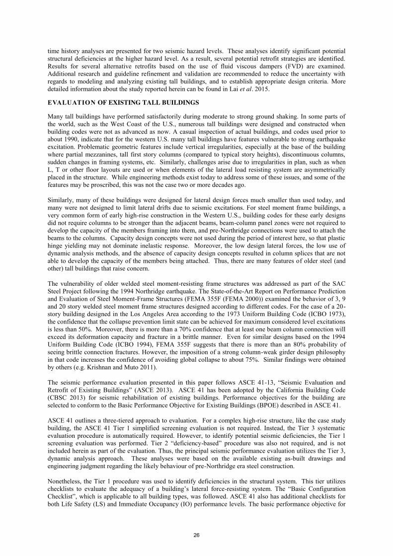
ANALYSIS RESULTS AND DISCUSSION ASCE 41 stipulates a number of specific evaluations. For the case study building, a series of nonlinear analyses are to be carried out. However, to better understand the behavior of the structure, the simplified Tier 1 checklist approach is used to identify the types of deficiencies that need to be modeled carefully. In addition, series of nonlinear analysis procedures (static pushover analyses) were undertaken to help identify vulnerable regions of the structure. Seismic Deficiencies Identified From Tier 1 Screening The simplified Tier 1, checklist based structural evaluations are not required for this type of structure according to ASCE 41. However, these simple checks identified a number of possible deficiencies, including a potential soft story at the mezzanine level. Several other deficiencies are also identified, such as high column stress levels, pre-Northridge beam-to-column connection details, panel zone details, not passing the strong-column weak-beam (SCWB) check, column bases not anchored to the foundation, diaphragm openings at mezzanine level and metal decks are connected to steel frames with only puddle welds (no shear studs were used). In some cases, welds used to fabricate built-up sections are insufficient to develop member flexural capacities. Detail checklists are presented in the appendix of the project report (Lai et al. 2015). Nonlinear Static Pushover Curves Nonlinear static pushover analysis typically is not permitted for tall buildings, since higher mode effects are not realistically taken into account. However, such analyses provide basic comparative information on post-yield behavior. Figure 5 shows pushover curves and deformed shapes at selected roof displacements of the four models with loads applied in the Y direction. The lateral load pattern used was the same as the first mode shape. The shear capacity in both directions is about 13,700 kips (equivalent to about 10% of building weight). Significant P-' effects can be inferred from the structure’s negative post-yield tangent lateral stiffness for models 1a and 1b. Note that the design base shear (2,993 kips) per 1967 Uniform Building Code (ICBO, 1964) for the prototype building is only 2.2% of building weight; about 45% of the required design base shear (6,650 kips) per the current edition of ASCE 7 (ASCE, 2010). The star symbol markers on the pushover curves indicate roof displacements corresponding either to first significant yielding or first column splice failure. Upward-pointing triangle makers indicate the roof displacements at peak base shear. Cross markers indicate the roof displacements when simulation terminated or numerical model became unstable. Clearly, story drifts concentrate between floor levels five and ten in all models. However, the mechanical behavior of the beam-to-column connection has a significant effect on the degree of concentration and system deformability. For example, Models 1c or 1d both exhibit substantial loss in lateral load resistance at a roof lateral displacement of about 30 in. While the column splice behavior has an important influence on overall lateral force-displacement behavior, this is secondary to the deterioration and failure of the beam-to-column connections. Tier 3 Evaluation (Nonlinear Dynamic Analysis) Nonlinear response history analyses were performed in OpenSees using BSE-1E and BSE-2E hazard level ground motions. Each hazard level ground motion set contained 20 records and each record contains three components (two-horizontal and one vertical). Only the results of models 1c (baseline model) and global responses are presented in this paper. Complete results for all eight models, and a comparison of cases with and without consideration of the vertical component of motion, can be found in Lai et al. 2015. Figure 6 displays the average story drift envelope distribution under BSE-1E and BSE-2E hazard level events. Median peak drifts are all less than 1.2% under BSE-1E events but rise to about 7.0% under BSE-2E events. Computed peak story drift ratios are as large as 46% under BSE-1E events and 55% under BSE-2E events,
Figure 5 Static pushover curves and deformed shapes of four models (Y-Direction)
29

significantly larger than the peak 4.5% limit permitted by several criteria (e.g., LATBSDC (2014)). Note that Figure 6 only shows the story drift up to 2.5% and 7.5% for each hazard level. Drifts in some stories exceed these values. Obviously, results show a tendency towards soft story behavior in the bottom third of the structure.
a. Model 1c, BSE-1E hazard level b. Model 1c, BSE-2E hazard level
Figure 6 Story drift envelops (Y-Direction)
Maximum story shear demands for the BSE-1E and BSE-2E level events are both about 15,000 kips; similar to the value predicted by the static pushover analysis. Median peak beam end total rotation demands for BSE-1E and BSE-2E events are as large as 1.2% and 9%, and follow the trend for story drift, concentrating in the bottom one third of the building (Figure 7). In terms of percentage of beam-to-column connections at a floor level that lose their moment capacities (beam ends rotation demands larger than collapse prevention criteria per ASCE 41), the median percentage can be as high as 30% under BSE-2E events (Figure 8). Even for the BSE-1E level excitation, some ground motion records would be expected to fracture a significant number of connections in the lower half of the structure
Observations Regarding Evaluation The computed response of the prototype building does not satisfy the targeted performance objectives according to ASCE 41 (damage control state under BSE-1E events or limited safety state under BSE-2E events). Several specific seismic deficiencies were identified during the evaluation procedure. It is found that the case study building has a tendency to form weak story regions in its lower third. Pre-Northridge beam-to-column connection details result in a high percentage of connection failure under BES-2E events. High column stress demands, fracture vulnerable column splice details, beams and columns not conforming to the strong-column weak-beam criterion and no anchorage between column bases to foundation were also found during the Tier 1 screening. Although results presented herein do not consider column splice failures, they are considered in the
Figure 7 Beam ends total rotation envelope for Model 1c, BSE-2E hazard level
a. Model 1c, BSE-1E hazard level b. Model 1c, BSE-2E hazard level Figure 8 Beam-to-Column Connection Failure Rate
30
overall evaluation of the building. From a review of the seismic evaluation results, it is suggested to retrofit the building. The feasibility of such a retrofit remains a question that is addressed in the next section. RETROFIT FEASIBILITY ASSESSMENT A number of different approaches are possible for retrofit. One approach is to increase the inelastic deformation capacity of the existing connections. However, while Model 1a described previously with ideally ductile beam-to-column connections and ductile column splices was able to develop the full capacity of the columns but resulted in very large story drift demands between levels 5 and 10, and substantial residual displacements. Even if the analytical results (not shown) suggested acceptable seismic response, the large number of difficult to access, beam-to-column connections needing retrofit would likely make this approach economically prohibitive. Thus, it appears that an approach that would reduce story drift deformation demands, beam ends rotational demands, and the tendency of the structure to form a weak story mechanism should be explored. The lack of column attachment at the foundation and the fragility of the columns, pose significant challenges to stiffening the building by adding strong centralized bracing or wall elements. Retrofit schemes such as adding distributed velocity- or displacement-dependent bracing devices (Wang et al. 2015) to the current lateral force resisting frames or implementing mid-level isolation systems might be considered. To provide the required lateral stiffness and energy dissipation needed to reduce lateral displacements, while not increasing the strength of the structure, is a challenge. Common approaches in the U.S. would be to consider the addition of buckling restrained braces or fluid viscous dampers. Because of the fragility of the columns in compression and tension, an approach using fluid viscous dampers has been explored in some detail. In this approach, the ability of the fluid viscous dampers to result in peak force resistance that is out of phase with the forces acting in structural elements may provide a way to limit drifts but not create excessive demands on the columns and other structural elements. Several other alternatives that might be considered including reducing the force demands on the system by reducing the weight of the structure. For instance, the heavy cladding used on the building could be replaced with a much lighter curtain wall system. Similarly, an isolation system might be added to the building above the mezzanine level. This option introduces substantial changes in the architecture components, elevators, stairs, utilities and structure near the base of the structure. Thus, the initial focus is placed on fluid viscous dampers. A Fluid Viscous Damper (FVD) is a velocity-dependent energy dissipation device. Numerical and experimental investigations have both shown merits of such devices (Reinhorn et al. 1995; Symans et al. 1998; Miyamoto et al. 1971). More recently, probabilistic risk assessments have been made of steel moment frames with FVD (Miyamoto 2010). One of the largest advantages of FVD is its forces tend to be out-of-phase with forces in elastic structural members. This avoids the peak damper force occurring concurrently with forces in other elements, thus limiting the maximum force developed by the structure. Considerable research in the 1990s resulted at least five code-oriented procedures for designing passive energy dissipation systems (Ramirez et al. 2001). Those guidelines and codes such as ASCE 41-13 and ASCE 7-10 provide methods to account for the supplemental damping effects of these devices by modifying the design spectrum. In this way, damper characteristics can be selected to achieve basic performance goals. However, they do not prescribe specific methods for optimally placing dampers in a building, and damper placement could have large impacts on both structural behavior and the cost of using dampers. A wide variety of methods have been suggested to identify optimal damper placement (e.g. Apostolakis and Dargush 2010; Balling and Pister 1983; Garcia and Soong 2002; Gluck et al. 1996; Lavan and Dargush 2009; Lee et al. 2004; Levy and Lavan 2006; Singh and Moreschi 2001, 2002; Takewaki 2000; Yang et al. 2002; Zhang and Soong 1992). Most of the aforementioned methods focus on FVD in low- to median-rise buildings. Intensive computation is needed to optimize the distribution of dampers and their properties, even for these structures. Whittle et al. (2012) compared two conventional design methods and three advanced optimizations methods and showed that even for computationally efficient optimization algorithms the total computation time required for a ten-story building was 10-50 times that for a conventional design method. For a far taller building, having complex, three-dimensional, nonlinear dynamic behavior, typical optimization algorithms are not expected to be computationally efficient. Thus, in this paper, selecting potential FVD configurations and properties starts by examining three conventional schemes, and then assessing their advantages and limitations. Improved designs are then proposed based on the findings for these initial schemes.
31

Modeling of Retrofit Alternatives For the feasibility study, the retrofit design focuses primarily on a hazard level corresponding to the Basic Safety Earthquake, Level 2 for existing buildings (BSE-2E). The intent of the retrofit is to reduce the concentration of drifts in the lower levels (stories 5-10) compared to other stories, and to reduce the overall drifts of the structure to a level where brittle fracture of the beam to column connections are limited to the point where they do not seriously jeopardize the overall stability of the structure under the BSE-2E excitations. It is assumed that the columns splices will need to be retrofit in multiple places in the structure to prevent this undesirable failure mode. Similarly, it is assumed that the heavy perimeter cladding will be replaced with lighter weight curtain walls. As a consequence, the basic numerical model for the building used for the retrofit studies is Model 1c (Table 1) that has “brittle” beam-to-column connections, and ductile column splices. To streamline the analysis process during preliminary feasibility studies, only three three-component ground motion sets are used. As stipulated by ASCE 41, the largest response value computed for a parameter of interest is used to assess the performance of the system. The ground motions used were selected based on the closeness of their pseudo-acceleration spectra to the target spectrum at the fundamental period of the as-built structure. Selection of Initial VFDs Figure 9 shows a sketch of the plan view of a typical floor, where the black boxes indicate column locations. The interior frames are usually adjacent to stairs and elevator locations, and putting dampers there would interfere with office space and egress. Therefore, dampers were added only to the perimeter frames. As a first trial, dampers were stacked above one another within single bays, as indicated by the cross lines in the plan view. However, this resulted in a significant accumulation of damper forces in the adjacent columns and this approach was discarded. As such, the dampers were distributed diagonally across the structure, Figure 9. It is assumed here that the heavy precast cladding panels in the actual building are removed to reduce the weight of the structure, and facilitate damper installation.
As a first trial, dampers were stacked above one another within single bays, which is indicated by the cross lines in the plan view. However, this resulted in a significant accumulation of damper forces in the adjacent columns and this approach was discarded. As such, the dampers were distributed across the structure, as seen in Figure 2, to minimize this accumulation. The odd number of bays in the longitudinal direction of the building resulted in a skewed distribution of dampers. Effective damping needed. -- Estimating the overall effective damping (including the intrinsic damping and supplemental damping from the FVDs) needed to reduce the overall drifts and drift concentrations to acceptable levels is a crucial first step in selecting the appropriate number and size of dampers. For this preliminary study, a simple and direct approach is used. Several guidelines and codes provide damping coefficients to modify the design response spectrum to account for damping values other than 5%. The values are typically derived based on responses of simple structural systems to a limited selection of ground motions, not including records on soft soil sites and from near-fault sites (Ramirez 2001). In this paper, a spectrum modification approach developed by Rezaeian (2012) is used. In this approach a Damping Scale Factor (DSF) was developed to adjust 5% damped spectral ordinates to damping ratio ranges between 0.5 to 30%. These factors are based on analyses using the entire NGA West2 earthquake record set. Here, the target acceptance criterion is based on the roof drift at which the as-built structure suddenly loses significant strength. This was simply done by examining Figure 5. For Model 1c, the roof displacement at which the structure exhibits a sudden loss of capacity was identified. For the X-Direction, this was about 38 in. Simplified methods in FEMA 41-13 were then used to assess the expected roof displacement for the BSE-2E excitation. This resulted in an estimated roof displacement in the X-Direction of 48 in. As a result a DSF of (38/49=) 0.79 is needed in this direction. The value of required damping to achieve this DSF was estimated from the regression analysis equation proposed by Rezaeian (Rezaeian et al. 2012). Following this procedure, no additional damping is required for the BSE-1E level earthquake. However, for the BSE-2E hazard level, an effective damping ratio of 10% and 15% for the X-direction and Y-direction,
Figure 9 Plan view and exterior elevations of case
study building showing trial placement of dampers
32

respectively, are required. For comparison, damping tables contained in ASCE 7-10 suggest 12% and 18% effective damping for the same BSE-2E level target roof displacement for the X- and Y-directions, respectively. Thus, the method presented here requires a bit less damping that estimated using standard code requirements. However, the method used selects the performance target from the pushover curve of the specific building and uses improved DSF that considers variations of magnitude, source-to-site distance, local site conditions; also, this method designed the two horizontal directions separately. The validity of this method will be demonstrated below using the results of nonlinear dynamic analyses of the retrofit building models. The effective damping ratio relates to designing the damping constants C of the FVDs, a parameter related to the damper force by the equation: F = C𝑉𝛼. The set of C values are calculated based on the strain energy method in ASCE 41-13, considering both linear dampers and nonlinear dampers: The structure’s first mode frequency and mode shape were used in conjunction with the desired effective damping ratio to identify the C coefficients for linear FVDs (with α=1). Three distributions of C over the height of the building were considered: I) Uniform damping constant; II) Damper force proportional to story shear demand; and III) Damping constant proportional to story stiffness. The in-line brace used to drive the brace was given stiffness equal to twice the story stiffness. The braces were arranged as shown in Figure 9. Structural Response. -- Peak story drift, floor displacement and floor acceleration envelopes are examined to check the effectiveness of the three damping systems. The maximum value for the three time history analyses is used to compare the different systems. Only X direction responses are presented in this paper. Figures 10 and 11 show envelops of maximum story displacement and maximum story drift. All three design schemes help reduce the story drift ratio by about 20%-30%, and by a much larger amount in stories 5 through 9. Scheme II is the least effective. Schemes I and III are more effective with Scheme III being slightly more effective in reducing the peak story drift ratio. In this later case the maximum peak story drift is about 1.3%, which is acceptable under the BSE-2E level earthquake (LATBSDC 2014; ASCE 41-13). Figure 15 shows that the average peak roof displacement is about 38 in. for all three cases, validating the method used to calculate the effective damping ratio for the initial retrofit. Figure 16 shows the maximum peak floor acceleration envelope. All of the FVDs reduce the floor accelerations, especially those that appear to be associated with higher mode effects. The peak accelerations in the structures with supplemental damping are about 0.7g, which represents about a 30% reduction. Another benefit of FVDs is that it results in a rapid decay of structural vibrations at the end of the earthquake. The reduction of both story drifts and floor accelerations could help reduce both structural and non-structural damage, and reduce the fear and discomfort of occupants.
Figure 10 Peak floor displacement in Figure 11 Peak Story Drift in X-direction (BSE-2E) X-direction (BSE-2E) Damper response. -- The damper force demand envelopes are shown in Figure 12. All cases give fairly large damper forces, with the maxima ranging from 1600 kips to 2300 kips, at the lower stories. While such large
33
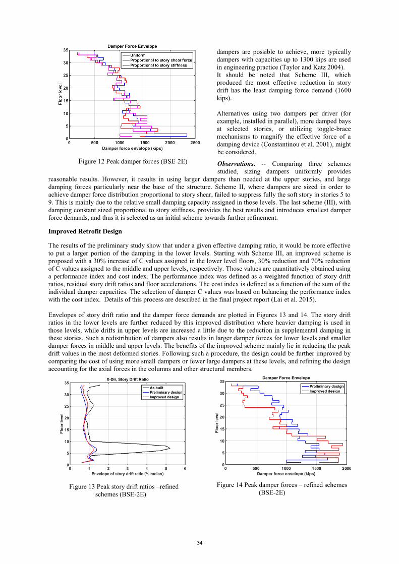
dampers are possible to achieve, more typically dampers with capacities up to 1300 kips are used in engineering practice (Taylor and Katz 2004). It should be noted that Scheme III, which produced the most effective reduction in story drift has the least damping force demand (1600 kips). Alternatives using two dampers per driver (for example, installed in parallel), more damped bays at selected stories, or utilizing toggle-brace mechanisms to magnify the effective force of a damping device (Constantinou et al. 2001), might be considered.
Observations. -- Comparing three schemes studied, sizing dampers uniformly provides
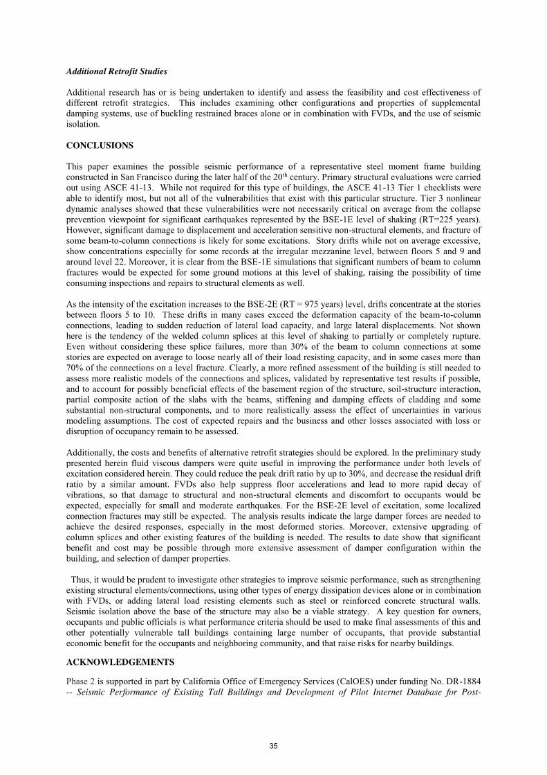
reasonable results. However, it results in using larger dampers than needed at the upper stories, and large damping forces particularly near the base of the structure. Scheme II, where dampers are sized in order to achieve damper force distribution proportional to story shear, failed to suppress fully the soft story in stories 5 to 9. This is mainly due to the relative small damping capacity assigned in those levels. The last scheme (III), with damping constant sized proportional to story stiffness, provides the best results and introduces smallest damper force demands, and thus it is selected as an initial scheme towards further refinement. Improved Retrofit Design The results of the preliminary study show that under a given effective damping ratio, it would be more effective to put a larger portion of the damping in the lower levels. Starting with Scheme III, an improved scheme is proposed with a 30% increase of C values assigned in the lower level floors, 30% reduction and 70% reduction of C values assigned to the middle and upper levels, respectively. Those values are quantitatively obtained using a performance index and cost index. The performance index was defined as a weighted function of story drift ratios, residual story drift ratios and floor accelerations. The cost index is defined as a function of the sum of the individual damper capacities. The selection of damper C values was based on balancing the performance index with the cost index. Details of this process are described in the final project report (Lai et al. 2015). Envelopes of story drift ratio and the damper force demands are plotted in Figures 13 and 14. The story drift ratios in the lower levels are further reduced by this improved distribution where heavier damping is used in those levels, while drifts in upper levels are increased a little due to the reduction in supplemental damping in these stories. Such a redistribution of dampers also results in larger damper forces for lower levels and smaller damper forces in middle and upper levels. The benefits of the improved scheme mainly lie in reducing the peak drift values in the most deformed stories. Following such a procedure, the design could be further improved by comparing the cost of using more small dampers or fewer large dampers at these levels, and refining the design accounting for the axial forces in the columns and other structural members.
Figure 14 Peak damper forces – refined schemes (BSE-2E)
Figure 12 Peak damper forces (BSE-2E)
Figure 13 Peak story drift ratios –refined schemes (BSE-2E)
34
Additional Retrofit Studies Additional research has or is being undertaken to identify and assess the feasibility and cost effectiveness of different retrofit strategies. This includes examining other configurations and properties of supplemental damping systems, use of buckling restrained braces alone or in combination with FVDs, and the use of seismic isolation. CONCLUSIONS This paper examines the possible seismic performance of a representative steel moment frame building constructed in San Francisco during the later half of the 20th century. Primary structural evaluations were carried out using ASCE 41-13. While not required for this type of buildings, the ASCE 41-13 Tier 1 checklists were able to identify most, but not all of the vulnerabilities that exist with this particular structure. Tier 3 nonlinear dynamic analyses showed that these vulnerabilities were not necessarily critical on average from the collapse prevention viewpoint for significant earthquakes represented by the BSE-1E level of shaking (RT=225 years). However, significant damage to displacement and acceleration sensitive non-structural elements, and fracture of some beam-to-column connections is likely for some excitations. Story drifts while not on average excessive, show concentrations especially for some records at the irregular mezzanine level, between floors 5 and 9 and around level 22. Moreover, it is clear from the BSE-1E simulations that significant numbers of beam to column fractures would be expected for some ground motions at this level of shaking, raising the possibility of time consuming inspections and repairs to structural elements as well. As the intensity of the excitation increases to the BSE-2E (RT = 975 years) level, drifts concentrate at the stories between floors 5 to 10. These drifts in many cases exceed the deformation capacity of the beam-to-column connections, leading to sudden reduction of lateral load capacity, and large lateral displacements. Not shown here is the tendency of the welded column splices at this level of shaking to partially or completely rupture. Even without considering these splice failures, more than 30% of the beam to column connections at some stories are expected on average to loose nearly all of their load resisting capacity, and in some cases more than 70% of the connections on a level fracture. Clearly, a more refined assessment of the building is still needed to assess more realistic models of the connections and splices, validated by representative test results if possible, and to account for possibly beneficial effects of the basement region of the structure, soil-structure interaction, partial composite action of the slabs with the beams, stiffening and damping effects of cladding and some substantial non-structural components, and to more realistically assess the effect of uncertainties in various modeling assumptions. The cost of expected repairs and the business and other losses associated with loss or disruption of occupancy remain to be assessed. Additionally, the costs and benefits of alternative retrofit strategies should be explored. In the preliminary study presented herein fluid viscous dampers were quite useful in improving the performance under both levels of excitation considered herein. They could reduce the peak drift ratio by up to 30%, and decrease the residual drift ratio by a similar amount. FVDs also help suppress floor accelerations and lead to more rapid decay of vibrations, so that damage to structural and non-structural elements and discomfort to occupants would be expected, especially for small and moderate earthquakes. For the BSE-2E level of excitation, some localized connection fractures may still be expected. The analysis results indicate the large damper forces are needed to achieve the desired responses, especially in the most deformed stories. Moreover, extensive upgrading of column splices and other existing features of the building is needed. The results to date show that significant benefit and cost may be possible through more extensive assessment of damper configuration within the building, and selection of damper properties. Thus, it would be prudent to investigate other strategies to improve seismic performance, such as strengthening existing structural elements/connections, using other types of energy dissipation devices alone or in combination with FVDs, or adding lateral load resisting elements such as steel or reinforced concrete structural walls. Seismic isolation above the base of the structure may also be a viable strategy. A key question for owners, occupants and public officials is what performance criteria should be used to make final assessments of this and other potentially vulnerable tall buildings containing large number of occupants, that provide substantial economic benefit for the occupants and neighboring community, and that raise risks for nearby buildings. ACKNOWLEDGEMENTS Phase 2 is supported in part by California Office of Emergency Services (CalOES) under funding No. DR-1884 -- Seismic Performance of Existing Tall Buildings and Development of Pilot Internet Database for Post-
35

Earthquake Applications. Any findings, opinions and conclusions or recommendations expressed in this paper are those of the authors and do not necessarily reflect the views of other organizations or individuals. The assistance of Dr. Frank McKenna and Dr. Andreas Schellenberg in helping develop the OpenSees numerical models presented in this paper is gratefully acknowledged. REFERENCES Apostolakis, G. and Dargush, G. F. (2010). “Optimal seismic design of moment-resisting steel frames with
hysteretic passive devices”, Earthquake Engineering and Structural Dynamics, 39: 355-376. ASCE (2010). “Minimum Design Loads for Buildings and Other Structures”, American Society of Civil
Engineers, ASCE/SEI 7-10, Reston, VA. ASCE (2014). “Seismic Evaluation and Retrofit of Existing Buildings”, American Society of Civil Engineers,
ASCE/SEI 41-13, Reston, VA. Baker, J. W. (2014). “Ground Motions for PEER Tall Buildings Project”, unpublished in-house report. Balling, R. J. and Pister, K. S. (1983). “Optimal seismic-resistant design of a planar steel frame”, Earthquake
Engineering and Structural Dynamics, 11: 541-556. CBSC (2013). “California Building Code”, California Code of Regulations, Title 24, Part 2, Volumes 1 and 2,
California Building Standards Commission, Sacramento, CA. Chen, Y.-T. and Chai, Y. H. (2011). “Effects of brace stiffness on performance of structures with supplemental
Maxwell model-based brace-damper systems”, Earthquake Engineering and Structural Dynamics, 40: 75-92.
Constantinou, M.C., Tsopelas, T., Hammel, W. and Sigaher, A. N. (2001). “Toggle-brace-damper seismic energy dissipation systems”, Journal of Structural Engineering, 127:105-112.
Department of Building Inspection (DBI) (2013), San Francisco, CA. FEMA (2012). “Seismic Performance Assessment of Buildings”, FEMA Report P-58, Federal Emergency
Management Agency, Washington DC, Sept. Garcia, D. L. and Soong, T. T. (2002). “Efficiency of a simple approach to damper allocation in MDOF
structures”, Journal of Structural Control, 9: 19-30. Gluck, N., Reinhorn, A. M., Gluck, J. and Levy, R. (1996). “Design of supplemental dampers for control of
structures”, Journal of Structural Engineering, 122: 1394-1399. Holmes, W., Kircher, C., Petak, W. and Youssef, N. (2008). “Seismic Performance Objectives for Tall
Buildings”, Report PEER 2008/101, Pacific Earthquake Engineering Research Center, Univ. of California, Berkeley.
ICBO (1973, 1997). Uniform Building Code, International Conference of Building Officials, Whittier, CA. Lai, J. W., Wang, S. Schoettler, M. and Mahin, S. (2015). “Seismic Evaluation and Retrofit of Existing Tall
Steel Buildings: Case Study of a 35-story Steel Moment-Resisting Frame Building in San Francisco, California”, PEER Report (in preparation), Pacific Earthquake Engineering Research Center, Berkeley, CA.
LATBSDC (2014). “An alternative Procedure for Seismic Analysis and Design of Tall Buildings Located in the Los Angeles Region”, Los Angeles Tall Buildings Structural Design Council, Los Angeles, CA.
Lavan, O. and Dargush, G. F. (2009). “Multi-objective evolutionary seismic design with passive energy dissipation systems”, Journal of Earthquake Engineering, 13:758-790.
Lee, S.-H., Son, D.-I., Kim, J. and Min, K.-W. (2004). “Optimal design of viscoelastic dampers using eigenvalue assignment”, Earthquake Engineering and Structural Dynamics, 33:521-542.
Levy, R. and Lavan, O. (2006). “Fully stressed design of passive controllers in frames structures for seismic loading”, Structural Multidiscipline Optimization, 32: 485-498.
McKenna, F. and Fenves, G. (2001). "The OpenSees Command Language Manual: version 1.2", Pacific Earthquake Engineering Center, Univ. of Calif., Berkeley. (http://opensees.berkeley.edu).
Miyamoto, H. K. and Scholl, R. E. (1971). “Case study: seismic rehabilitation of a non-ductile soft story concrete structure using viscous dampers”, Proceedings of the 11th World Conference on Earthquake Engineering, Acapulco, Mexico, No. 315.
Miyamoto, H.K. (2010). “Probabilistic Seismic Risk Identification of Steel Buildings with Viscous Dampers”, Doctoral Dissertation, Tokyo Institute of Technology, Tokyo.
NIST (2012). “Soil-Structure Interaction for Building Structures”, NEHRP Consultants Joint Venture, NIST GCR 12-917-21 (ATC-83 report), National Institute of Standards and Technology.
PEER (2010a). “Guidelines for Performance-based Seismic Design of Tall Buildings”, PEER Report 2010/05, Pacific Earthquake Engineering Research Center, University of California, Berkeley.
PEER (2010b). “Modeling and Acceptance Criteria for Seismic Design and Analysis of Tall Buildings”, Report PEER 2010/111, Pacific Earthquake Engineering Research Center, University of California, Berkeley.
PEER (2011). "Case Studies of the Seismic Performance of Tall Buildings Designed by Alternative Means”, PEER Report 2011/05, Pacific Earthquake Engineering Research Center, Univ. of California, Berkeley.
36
Porter, K. (2009). “An Overview of PEER’s Performance-Based Earthquake Engineering Methodology”, Proceedings of the Ninth International Conference on Applications of Statistics and Probability in Civil Engineering (ICASP9), San Francisco.
Reinhorn, A. M., Li, C. and Constantinou, M. C. (1995). “Experimental and analytical investigation of seismic retrofit of structures with supplemental damping, part I: fluid viscous damping devices”, Report NCEER-95-0001, University of Buffalo, Buffalo, NY.
Ramirez, O. M., Constantinou, M. C., Kircher, C. A., Whittaker, A. S., Johnson, M. W., Gomez, J. D. and Chrysostomou, C. Z. (2001). “Development and evaluation of simplified procedures for analysis and design of buildings with passive energy dissipation systems”, Report MCEER-00-0010, Univ. of Buffalo, NY.
Rezaeian, S., Bozorgnia, Y., Idriss, I. M., Campbell, K., Abrahamson, N. and Silva, W., “Spectral damping scale factors for shallow crustal earthquakes in active tectonic regions”, Report PEER 2012/01, Pacific Earthquake Engineering Research Center, University of California, Berkeley, CA.
Ribeiro, F., Barbosa, A., Scott, M. and Neves, L. (2015). “Deterioration Modeling of Steel Moment Resisting Frames Using Finite-Length Plastic Hinge Force-Based Beam-Column Elements”, Journal of Structural Engineering, Vol. 141, Issue 2.
SFDBI (2014). “Requirements and Guidelines for the Seismic Design of New Tall Buildings using Non-Prescriptive Seismic-Design Procedures”, Administrative Bulletin 83, San Francisco Building Code, San Francisco Department of Building Inspection, San Francisco.
Symans, M. D. and Constantinou, M. C. (1998). “Passive fluid viscous damping systems for seismic energy dissipation”, ISET Journal of Earthquake Technology, vol. 35, No.4, p.185-206.
Singh, M. P. and Moreschi, L. M. (2001). “Optimal seismic response control with dampers”, Earthquake Engineering and Structural Dynamics, 30: 553-572.
Singh, M. P. and Moreschi, L. M. (2002). “Optimal Placement of Dampers for Passive Response Control”, Earthquake Engineering and Structural Dynamics, 31: 955-976.
Stewart, J. and Tileylioglu, S. (2010). “Input ground motions for Tall Buildings with Subterranean Levels”, TBI Task 8 Final Report, Pacific Earthquake Engineering Research Center, University of California, Berkeley.
Takewaki. I. (2000). “Optimal Damper Displacement for Planar Frames using Transfer Functions”, Structural Multidisciplinary Optimization, 20: 280-287.
Taylor, D. P. and Katz, I. (2004). “Seismic Protection with Fluid Viscous Dampers for the Torre Mayor”, North Tonawanda: Taylor Devices, Inc.
Terzic, V., Mahin, S. and Comerio, M, “Using PBEE in Seismic Design to Improve Performance of Moment Resisting Frames by Base-Isolation”, Earthquake Spectra, EERI, in press.
Whittle, J. K., Williams, M. S., Karavasillis, T. L. and Blakeborough, A. (2012). “A comparison of viscous damper placement methods for improving seismic building design”, J. of Earthquake Engineering, 540-560.
Yang, J. N., Lin, S., Kim, J.-H. and Agrawal, A. K. (2002). “Optimal design of passive energy dissipation systems based on H∞ and H2 performances”, Earthquake Engineering and Structural Dynamics, 31: 921-936.
Zhang, R.-H. and Soong, T. T. (1992). “Seismic design of viscoelastic dampers for structural applications”, Journal of Structural Engineering, 118: 1375-1392.
37