evacuation platforms section i. army … platforms section i. army ground ambulances a. ground...
TRANSCRIPT

FM 8-10-6
10-1. General
CHAPTER 10
EVACUATION PLATFORMS
Section I. ARMY GROUND AMBULANCES
a. Ground ambulances are vehicles designedfor or converted to carrying patients. They areorganic to HSS units which evacuate sick, injured,and wounded soldiers by ground ambulance. Thesevehicles are equipped with an MES designed for usein these ambulances.
b. They are staffed with a driver/medicalaidman and an additional medical aidman who areboth qualified in basic EMT procedures.
c. The Geneva Conventions stipulate thatground ambulances be clearly marked with thedistinctive emblem (red cross on a white back-ground). To camouflage or not display this emblemwill result in the loss of the protections affordedunder these conventions. Guidance on the camou-flage of medical units, vehicles, and aircraft on theground is contained in STANAG 2931 OP (para-graph B-2b).
10-2. Ground Ambulances
Vehicles designed as ambulances include field(wheeled) ambulances, the bus ambulance, and theM113 (track) armored personnel carrier.
a. Military field ambulances, designed foruse by field units, operate on paved and secondaryroads, trails, and cross-country terrain. Fieldambulances operating in the forward areas of the CZmust possess mobility and survivability comparableto the units being supported. Current fieldambulance variations include the M1010, HMMWV(M996 and M997), and M113. The M996 and M997are normally used to evacuate patients fromfrontline units to BASs. The M792, M170, andM718 are being phased out of the inventory.
b. The bus ambulances are usefuI intransporting large numbers of patients within theCOMMZ.
c. The M113, when configured with a litterkit, an NBC kit, and an MES, is classified as a
standard evacuation vehicle and is thereforeincluded in this section on ground ambulances.
10-3. Ambulance Driver
The ambulance driver/medical aidman is responsiblefor the ambulance at all times. He performs drivermaintenance on the vehicle and is responsible forreporting major deficiencies to his section chief orsupervisor. When an additional medical aidman isnot assigned to the vehicle, the driver also performsaidman duties. The driver's responsibilitiesinclude—
Providing maximum safety and welfarefor the patients entrusted to his care. This includesensuring that the patient is secured to the litterprior to loading.
Ensuring operational readiness and re-sponsiveness. This is accomplished by maintainingand being able to use the authorized equipmentaboard the ambulance. This equipment includes—
equipment.
Litters.
Blankets.
Splints.
Medical expendable.
Flashlights.
Auxiliary fuel.
Decontamination equipment.
Special medical materials and
Preparing the ambulance for loading andunloading.
Assisting the litter bearers in the loadingand unloading of patients.
10-1

FM 8-10-6
Performing property exchange whenpatients are loaded or unloaded.
Transporting medical supplies andauthorized medical personnel.
Acting as a messenger in medicalchannels.
10-4. Medical Aidman
The medical aidman acts as the assistant driver andhis duties include—
Becoming familiar with the condition ofeach patient being evacuated and reviewing theinformation on the FMC.
Coordinating with the individual incharge for any special instructions in the care andtreatment of the patients en route.
en route.
Providing EMT as required.
Making periodic checks of patients while
Supervising and assisting in the properloading and unloading of the ambulance.
Assisting the driver with land navigationand guiding the driver when backing or moving offroads, or when under blackout conditions.
10-5. Ambulance Loading and Unloading
In loading and unloading ambulances, litterpatients are moved carefully. Details of the loadingand unloading procedures vary slightly dependingon the number of bearers, the presence or absence ofa medical aidman, and the type of vehicle used.
a. General Procedures.
Patients are normally loaded headfirst. The exception is if the nature of the patient’sinjuries make this inadvisable. They are less likelyto experience motion sickness or nausea with thehead in the direction of travel. They also experienceless noise from the opening and closing of rear
10-2
doors. There is less danger of injury to the patient ifa rear-end collision occurs.
When a patient requires en routecare for an injury to one side of the body, it may benecessary to load him feet first to make the injuredside readily accessible from the aisle. Patients withwounds of the chest or abdomen, or those receivingIV fluids are loaded in lower berths to providegravity flow. For ease of loading and patientcomfort, those patients wearing bulky splintsshould be placed on lower berths, if possible.
b. Instructional Procedures. For loadingand unloading the ambulances, the litter bearers arenumbered and formal commands are given so thateach individual can learn his particular job and workas a team.
(1) Loading procedures. The sequencefor loading four litter patients in the berths is upperright, lower right, upper left, and lower left. Themost seriously injured are loaded last so they will bethe first to be off-loaded. A three-man squad isrequired to load and unload the ambulance.
(2) Unloading procedures. The sequencefor unloading the ambulance is the reverse of theloading procedures: lower left, upper left, lowerright, and upper right. A three-man squad is neededto unload the ambulance.
Truck, Ambulances, 4x4, Armored, M996 andM997
The M996 and M997 armored ambulances aretactical vehicles designed for use over all types ofroads, as well as cross-country terrain. It can alsooperate in all weather conditions (Figure 10-1).These ambulances are diesel-powered and equippedwith four-wheel hydraulic service brakes. Theambulances can be heated and ventilated. Only theM997 can be air conditioned. Supplementalelectrical power to operate the life supportequipment is also available. For operations in anNBC environment, the M996 and M997 ambulancesare equipped with a gas-particulate filter unit(GPFU).
a. Patient Carrying Capacities. Refer toTable 10-1 for the various patient carryingcapacities.
10-6.

FM 8-10-6
10-3

FM 8-10-6
b. Two-Litter Configuration, M996. The (1) Assembling litter rail extensionsequence for loading patients in the berths is right (Figures 10-2 and 10-3).first then left. The most seriously injured patient isloaded last so that he is the first to be taken out of
(a) Turn latch (1) counterclockwise
the ambulance. The sequence for unloading is the and open stowage compartment door (2).
reverse of loading. (b) Loosen and disconnect secur-ing strap (3) and remove folded litter rail extension(4) from stowage compartment (5).
NOTE
The numbers used in the expla-nation of the figures correspond tothe parts/equipment represented inthe graphic.
(c) Pull left and right rails (6)apart and let legs (11) drop down. Ensure feet (12)are flat on ground.
(d) Lock support braces (13) andadjust straps (14) as necessary.
10-4

FM 8-10-6
(2) Loading litters on litter rack (Figure10-3).
(a) Secure both rails (6) of litterrail extension (4) into slots (10) on litter rack (9).
(b) Place litter (7) on litter railextension (4).
WARNING
Ensure straps and equipment do notinhibit litter loading operations. Loadlitters carefully to prevent patientinjury.
(c)
(d)with front and rear
Slide litter (7) onto litter rack (9).
Secure litter (7) to litter rack (9)litter handle straps (8).
(3) Unloading litters from the litter rack(Figure 10-3).
(a) Release front and rear litterhandle straps (8) securing litter (7) to litter rack (9).
(b) Secure both rails (6) of litterrail extension (4) into slots (10) on lower litter rack(9).
(c) Slide litter (7) from lower litterrack (9) onto litter rail extension (4). Lift up andremove litter (7) from litter rail extension (4).
(4) Fold and stow litter rail extension(Figures 10-2 and 10-3).
(a) Unlock support braces (13).
(b) Fold left and right rails (6)together.
(c) Fold left and right litter raillegs (11) and feet (12) against rails (6).
10-5

FM 8-10-6
(d) Place folded litter rail ex-tension (4) into stowage compartment (5) and securewith strap (3).
(e) Close door (2) and turn latch (1)clockwise to secure door (2).
(5) Opening patient seat to accom-modate ambulatory patients (Figures 10-4 and 10-5).
(a) Ensure litters are in stowedposition.
(b) Pull out and up on seat latchhandle (5) and remove latch (7) from catch (6).
(c) Lift seat back (4) to openposition and fold seat back support (2) into recessesbetween seat cushions (9).
(d) Ensure that seat braces (8) arefully extended and locked in position.
(6) Closing the patient seat toaccommodate litter patients (Figures 10-4 and 10-5).
(a) Press lock buttons (12) on seatbraces (8) and fold braces (8) toward seat back (4).
(b) Fold seat back support (2)outward and fold seat back (4) into closed position.Ensure that guide pins (11) on seat back supportengage holes (10) in seat base (3).
(c) Install seat back (4) to seatbase (3) with seat latch (7) and secure with latchhandle (5). If necessary, to ensure security of seatback (4), adjust seat latch (7) to proper length byturning clockwise or counterclockwise.
c. Four-Litter Configuration, M997. Thesequence for loading four litter patients in theberths is upper right, lower right, upper left, andlozuer left. The most seriously injured patients areloaded last so they are the first to be taken out of the
10-6

FM 8-10-6
ambulance. The sequence for unloading is the re-verse of the loading procedure: lower left, upper left,lower right, and upper right. When only two litterpatients are to be loaded the upper and lower rightside berths are used. Using the two right side berthsleaves the left side unoccupied for use in trans-porting ambulatory or additional litter patients.
NOTE
When patients are picked up fromseveral locations, the loadingsequence of least seriously injuredpatient to most seriously injuredpatient cannot always be applied. Apreviously loaded patient should notbe unloaded in order to maintain theloading sequence. The receivingMTF must be made aware of themost seriously injured patients.
WARNING
When loading more than two litterpatients, the upper litter rackpatients must be loaded first. Injurymay result if litter patients are loadedin lower rack first.
(1) Preparing the upper litter rack(Figure 10-6).
(a) Unhook tension strap (23) fromfootman loop (30) on lower litter rack (9).
(b) Pull out upper litter rackhandle (17) and support weight of upper litter rack(21).
10-7

FM 8-10-6
WARNING
The rear end of the upper litter mustbe supported before releasing thesuspension strap hook. Injury topersonnel may result if rear end ofupper litter is not supported.
(c) Unhook rear suspension straphook (27) from loop (22) on upper litter rack (21). Clipsuspension strap hook (27) to eye (26).
(d) Release litter support latchstop (25), push latch (24) in, and lower upper litterrack (21 ) onto lower litter rack (9).
(e) Slide litter rack handle (17 ) intoupper litter rack (21 ).
(2) Assembling litter rail extension(Figures 10-3 and 10-7).
(a) Turn latch (1) counterclockwiseand open stowage compartment door (2).
(b) Loosen and disconnect secur-ing strap (3) and remove folded litter rail extension(4) from stowage compartment (5).
(c) Lift tray (15) slightly and pushin tray supports (16) to lower tray (15) for access tostowed litters.
(d) Pull left and right rails (6)apart and let legs (11) drop down. Ensure feet (12)are flat on ground.
(e) Lock support braces (13) andadjust straps (14) as necessary.
10-8

FM 8-10-6
(3) Loading litters on upper litter racks(Figures 10-6 and 10-8).
(a) Secure both rails of litterextension (4) into slots in upper litter rack (21).
(b) Place litter (18) on litter railextension (4).
(c) Slide litter (18) up rails (4) untillitter (18) is clear of litter rail extension (4).
(d) Secure rear litter handles (19)to upper litter rack (21) with rear litter handle straps(20).
(e) Remove litter rail extension (4)from upper litter rack (21).
(f) Unhook suspension strap hook(27) from eye (26).
(g) Pull out upper litter rackhandle (17).
(h) Raise upper litter rack (21),push into litter support latch (24), and secure withlatch stop (25).
(i) Attach suspension strap hook(27) to loop (22) on upper litter rack (21).
(j) Secure front litter handles (29)to litter rack (21) with front litter handle straps (28).
10-9

FM 8-10-6
(k) Hook tension strap (23) to foot-man loop (30) on lower litter rack (9) and adjuststrap.
(l) Slide litter rack handle (17) intoupper litter rack (21).
(4) Loading litters on lower litter rack(Figure 10-3).
(a) Secure both rails (6) of litterrail extension (4) into slots (1 O) on lower litter rack(9).
(b) Place litter (7) on litter railextension (4).
(c) Slide litter (7) onto lower litterrack (9).
(d) Secure litter (7) to lower litterrack (9) with front and rear litter handle straps (8).
(5) Unloading litters from the lowerlitter rack (Figure 10-3).
WARNING
When unloading more than two litterpatients, lower litter rack patientsmust be unloaded first.
Ensure that straps and equipment donot inhibit unloading operations.Unload litters carefully to preventpatient injury.
(a) Release front and rear litterhandle straps (8) securing litter (7) to lower litterrack (9).
(b) Secure both rails (6) of litterrail extension (4) into slots (10) on lower litter rack(9).
(c) Slide litter (7) from lower litterrack (9) onto litter rail extension (4). Lift up andremove litter (7) from litter rail extension (4).
10-10
(6) Unloading litters from upper litterracks (Figure 10-6 and 10-8).
(a) Release front litter handlestraps (28) from litter handles (29).
(b) Unhook tension strap (23) fromfootman loop (30) on lower litter rack (9).
(c) Pull out upper litter rackhandle (17) and support weight of upper litter rack(21).
(d) Unhook rear suspension straphook (27) from loop (22) on upper litter rack (21). Clipsuspension strap hook (27) to eye (26).
(e) Release litter support latchstop (25), push latch (24) in, and lower upper litterrack (21) onto lower litter rack (9).
(f) Slide litter rack handle (17) intoupper litter rack (21).
(g) Secure rails of litter railextension (4) into slots in upper litter rack (21).
(h) Release rear litter handlestraps (20) from litter handles (19).
(i) Slide litter (18) down litter railextension (4) until litter (18) is clear of upper litterrack (21).
(j) Lift and remove litter (18) fromlitter rail extension (4).
(k) Remove litter rail extension (4)from upper litter rack (21).
(7) Fold and stow litter rail extension(Figure 10-3 and 10-7).
(a) Unlock support braces (13).
(b) Fold left and right rails (6)together.
(c) Fold left and right litter raillegs (11) and feet (12) against rail (6).

FM 8-10-6
(d) Lift tray (15) and push traysupports (16) in, and lower tray (15).
(e) Slide litters into stowagecompartment (5) on top of lift tray (15). Pull outsupports (16) to place lift tray (15) in raised position.
(f) Place folded litter rail ex-tension (4) into stowage compartment (5) and securewith strap (3).
(g) Close door (2) and turn latch (1)clockwise to secure door (2).
(8) Folding upper litter rack to thebackrest position (Figure 10-6).
(a) Unhook litter rack tensionstrap (23) from lower litter rack footman loop (30).
(b) Unhook two upper litter racksuspension straps hooks (27) from loops (22) onupper litter rack (21) and reattach strap hooks (27)to eyes (26).
(c) Release upper litter rack latch(31) and disengage rack striker (32) from latch (31).
(d) Lower upper litter rack (21)onto the lower litter rack (9), forming a backrest.
(9) Converting backrest to upper litterrack (Figure 10-6).
(a) Raise upper litter rack (21 ) andengage rack striker (32) into upper litter rack latch(31). Ensure striker (32) is locked in latch (31).
(b) Unhook two upper litter racksuspension strap hooks (27) from eyes (26) and hookto loops (22) on upper litter rack (21).
(c) Hook upper litter rack tensionstrap (23) to footman loop (30) on lower litter rack (9).
(d) Adjust straps (23) and (27) forproper tension.
10-11

FM 8-10-6
10-7. Truck, Ambulance, 1¼ Ton, 4x4, M1010
The M1010 truck, ambulance, (Figure 10-9) is adiesel-powered vehicle equipped with power steeringand brakes and automatic transmission. It canaccommodate up to four litter or eight ambulatorypatients, or a combination of each. The vehicle has apatient assist boom, and block and tackle forloading. An improved patient life support capability
is provided by four additional focus-type lights, airconditioning, optional GPFU for NBC protection,and supplemental electrical power to operate the lifesupport equipment. The M1010 also has additionalstorage space between the litter berths and vehiclecab. The loading sequence is upper right, lowerright, upper left, and lower left. In an emergency ormass casualty situation, one additional litter can beplaced in the center aisle.
10-8. Truck, Ambulance, 1¼ Ton, 6x6, M792 six ambulatory patients. Due to the ride character-istics of the vehicle, all litter patients must besecurely strapped in place. The sequence for loading
The M792 truck, ambulance, can accommodate the berths is upper right, upper left, and lower, withthree litter patients and a medical attendant (Figure the unloading sequence accomplished in reverse10-10), two litter patients, three ambulatory order. A two-man squad is required for loading andpatients, and a medical attendant (Figure 10-11), or unloading the vehicle.
10-12

FM 8-10-6
10-9. Truck, Ambulance, ¼ Ton, 4x4, M718,Frontline
The M718 truck ambulance (Figure 10-12), has nostorage compartment, blackout curtains, or addi-tional lights. A three-man squad is required forloading and unloading the vehicle, which can safelyaccommodate a driver and three or four other per-sons. This vehicle can be configured for—
a. Three litter patients in the upper left,upper right, and center berths. In this situation, theattendant must remain at the pickup site since theright front seat is placed against the instrument
panel to make space for the upper right and centerberths. This allows the driver to observe the mostsevere patients.
b. Two litter patients in the upper right andcenter berths and one ambulatory patient and theattendant seated on the left side. When the centerberth (placed diagonally) is occupied, seating spaceon the left side is adequate for only two persons.
c. The attendant in right front seat andthree ambulatory patients seated on the left side.The right side is used to store unused berths andlitters.
10-13

FM 8-10-6
10-10. Truck, Ambulance, ¼ Ton, 4x4, M170,Frontline CAUTION
The M170 ambulance (Figure 10-13) has no storagecompartment, blackout curtains, or additionallighting. It can accommodate three litter patients,two litter patients and three ambulatory patients, orfive ambulatory patients. A three-man squad isrequired for loading and unloading, The sequencefor loading three litter patients in the berths isupper right, lower right, and left.
Serious accidents can occur fromoverloading this ¼-ton vehicle. Itis a modification of the Ml51 utilityvehicle and is not designed to carryheavy loads.
10-11. Buses (Ambulances)
These vehicles can be rapidly converted intoambulances (Figures 10-14 and 10-15). They can beused in support of the Army in the field as farforward as the road network and tactical situationpermit. They are most useful in situations where alarge number of patients are to be transported forrelatively short distances over improved roads, suchas transferring patients from hospitals to airheadsand ports of embarkation.
a. Patient Carrying Capacity. Ambulancebuses have various patient carrying capacities.Total capacity for litter and ambulatory patientsdepends on the size of the available bus. A kitcontaining the necessary accessories for conversionis located in the compartment on the right outside ofthe bus body.
b. Vehicle Conversion. To convert the bus toan ambulance, it may be necessary to remove allseats except those immediately behind the driver.The seats behind the driver are used for medicalattendants or ambulatory patients, Litter supporthooks are inserted in brackets located at the top and
bottom on the interior of the body side. Littersupport hangers are then suspended from the hooksin the ceiling rails. To return the vehicle topassenger operation, the procedure is reversed. Insome buses, conversion can be done by folding downthe seat backs.
c. Loading Procedures. Normally, twothree-man litter squads are required to load andunload the bus ambulance. The vehicle is loadedfrom front to rear and from top to bottom. Allpatients are loaded into the bus with their headstoward the front of the vehicle unless the injurydictates using a different loading technique.
(1) Loading from ramps or platforms.Two litter teams are required to load the bus. Onelitter team enters the rear of the bus with a litterpatient, loads the patient on the berth, and exitsthrough the front as the second team enters throughthe rear with a litter patient. The second team loadsits patient and exits through the front as the firstteam enters the rear with its second patient. Onlyone of the teams is in the bus at a time, therebyavoiding interference.
10-14

FM 8-10-6
(2) Loading without ramps or plat- (1) When the vehicle is to be unleadedforms. Two litter teams are used to load the bus from loading ramps or platforms, the two litterfrom the ground. One litter team remains in the bus. teams alternate in unloading.A second litter team loads patients onto the busfloor at the rear of the bus where they are picked upby the team in the bus and loaded onto berths. (2) When the vehicle is to be unloaded
d. Unloading Procedures. Patients are without ramps, one litter team removes the litterunloaded (in reverse order of loading procedure) patients from the berths in the bus and places themfrom rear to front and from bottom to top. Two litter on the floor at the rear of the bus where they areteams are also required to unload the bus. picked up and unloaded by the second litter team.
10-15

FM 8-10-6
10-12. Carrier, Personnel, Full-Tracked, Armored,M113, T113E2
The Ml 13 armored personnel carrier (Figure 10-16)is a standard evacuation vehicle. It is lightlyarmored to afford patient protection against smallarms. Wearing the helmet inside the vehicleprovides added protection, especially over roughterrain, due to the low silhouette. Movement of thetracks propels and steers the vehicle. It is highlymaneuverable and capable of—
Amphibious operations on inland lakesand streams.
Extended cross-country travel over roughterrain.
High-speed operations on improved roadsand highways.
a. The vehicle can carry ten ambulatorypatients and has a conversion kit which, wheninstalled, gives a normal capacity of four litterpatients.
b. A squad of four men is needed to load andunload the vehicle. The sequence for loading fourlitter patients is upper right, lower right, upper left,and lower left.
CAUTION
To install the litter suspension kit inthe Ml 13 ambulance, the spanliner must be removed. Litterpatients cannot be safely moved ifthe litter suspension kit is notinstalled.
10-16
FM 8-10-6
Section II. NONMEDICAL VEHICLES USED FOR CASUALTYTRANSPORT AND MEDICAL EVACUATION
10-13. General
a. In combat areas, ambulances are oftenunavailable, are too few in number, or are incapableof evacuating patients over certain types of terrain.In these instances, many vehicles available to mostunits can be used to transport casualties with littleor no change in their configuration. Some amphibi-ous cargo and personnel vessels can be used for thispurpose; however, their patient-carrying capacityvaries.
b. When casualties have entered the HSSsystem, they are classified as patients. Patientevacuation includes providing en route medical careto the patient being evacuated. However, if acasualty is moved on a nonmedical vehicle withouten route medical care, he is considered to betransported not evacuated.
10-14. Casualty Transport and Patient Evacuationin a Mass Casualty Situation
To provide timely and responsive evacuation orcasualty transport, HSS planners develop proactiveOPLANs to meet the challenges of a mass casualtysituation.
Contingency plans should identify—
Nonmedical transportation re-sources.
Evacuation routes.
Ambulance exchange points.
Medical personnel resources to pro-vide en route medical care on nonmedical vehicles.
Capabilities and locations of MTFs.
Communications frequencies andcall signs for command and control.
Procedures for medical equipmentexchanges.
Key players in coordinating the use ofnonmedical vehicles for medical evacuation orcasualty transportation are contained in Table 4-2.
a. Ground nonmedical assets can be used forcasualty transport when the medical evacuationsystem is overwhelmed. All available groundvehicles should be considered for augmentingmedical evacuation assets in an emergency. The keyto success is identifying the vehicles, drivers, andmedical personnel or combat lifesavers who willaccompany the casualties. Coordinating for therelease of these assets upon demand rather thanwaiting for a mass casualty situation to occur is alsocrucial to the success of the operation. Vehicle typeswill differ depending upon the type of unit sup-ported; however, some of the more common vehicleswhich may be used are the—
Bradley infantry fighting vehicle,M2/3.
Light weapons carrier, M274.
Truck, cargo, 1¼ ton, M880/890and M1008.
Truck, cargo, 2½ ton, M35.
Truck, cargo, heavy expanded,mobility tactical truck (HEMTT), 8x8, cargo, M977.
Semi-trailer, cargo, 22½ ton,M871.
Truck, cargo, 5 ton.
Truck, utility, M151.
Armored personnel carrier, M113.
Tractor, 5 ton, with stake and plat-form trailer.
High-mobility, multi-purposewheeled vehicle, M998.
b. Depending on the theater of operations,host-nation support agreements may provide evac-
10-17
FM 8-10-6
uation assets ranging from austere to extensivesupport. Coordination with the G5 can provideinformation on the availability of assets. Thisinformation should be included in the OPLANs.Some of the types of assets which might be availablefor support are—
Buses.
Ambulance railcars (Chapter 3).
Barges and other watercraft(Chapter 5).
Civilian cargo vehicles.
c. The staffing of nonmedical vehicles withmedical personnel to provide en route medical carerequires considerable planning and coordination.Since nonmedical vehicles are normally ones ofopportunity, attendants, medical equipment, andtransportation platforms must be carefully trackedif they are to be used. The modular medical systemlends itself well to this form of task organizing byproviding four-man trauma treatment teams withequipment organic to the FSMCs and MSMCs.These same treatment modules are also found in thecorps ASMCs. Health service support managersshould plan to use these assets in this temporaryrole. Also available within the CS and CSS units ofthe division are trained combat lifesavers and theirMES (aid bags). These personnel can be used, ifavailable, to provide en route surveillance of lessseriously injured patients.
d. The management of patient evacuationusing nonmedical evacuation assets is difficult tocontrol. Overevacuation occurs routinely unlesscontrols are implemented to manage the evacueesby patient category. Responsive evacuation isextremely important; however, if en route patientcare and management by patient category areignored, the end result will be an increase in themortality rate and an overevacuation of RTDsoldiers. URGENT and URGENT-SURG prece-dence patients should be evacuated beforePRIORITY, ROUTINE, or CONVENIENCE pre-cedence patients. Care must be taken to ensurelower precedence patients are evacuated before theirmedical condition begins to deteriorate resulting inupgrading their precedence to URGENT orURGENT-SURG, The preferred means of evac-uating URGENT and URGENT-SURG precedencepatients is by air ambulance, If ground ambulance isused for URGENT and URGENT-SURG patients,the patients must be checked frequently to ensurethat their medical condition is not deteriorating andrendering them nontransportable. Planners shouldconsider and incorporate into the OPLAN the use ofnonmedical air assets and dedicated ground ambu-lances to move the PRIORITY patient, and non-medical ground vehicles to move the ROUTINE pre-cedence patients when dedicated medical vehiclesare not available. Every effort should be made tostaff and equip nonmedical vehicles used for patientevacuation with medical personnel, even if only tomove the ROUTINE patient precedence category.
e. Coordination for the use of nonmedicaltransportation resources is depicted in Table 10-2.
10-18

FM 8-10-6
10-19
FM 8-10-6
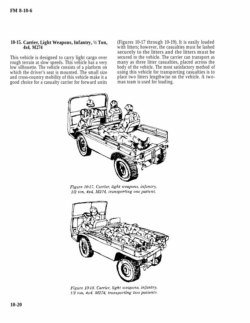
10-15. Carrier, Light Weapons, Infantry, ½ Ton,4x4, M274
This vehicle is designed to carry light cargo overrough terrain at slow speeds. This vehicle has a verylow silhouette. The vehicle consists of a platform onwhich the driver’s seat is mounted. The small sizeand cross-country mobility of this vehicle make it agood choice for a casualty carrier for forward units
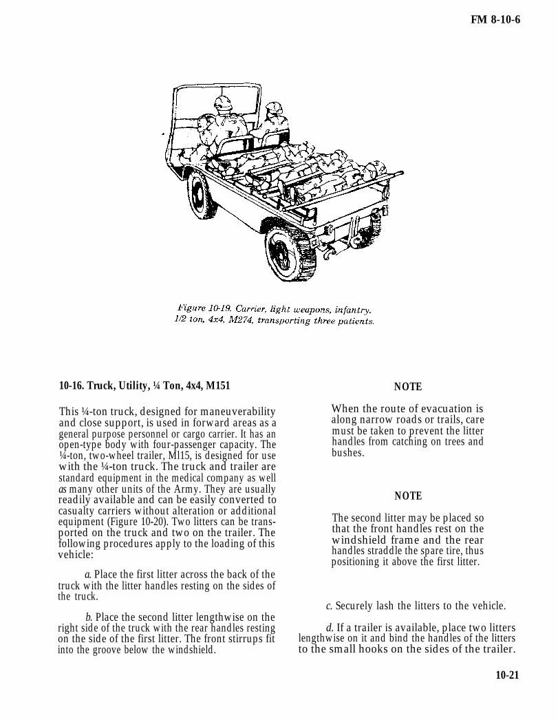
(Figures 10-17 through 10-19). It is easily loadedwith litters; however, the casualties must be lashedsecurely to the litters and the litters must besecured to the vehicle. The carrier can transport asmany as three litter casualties, placed across thebody of the vehicle. The most satisfactory method ofusing this vehicle for transporting casualties is toplace two litters lengthwise on the vehicle. A two-man team is used for loading.
10-20
FM 8-10-6
10-16. Truck, Utility, ¼ Ton, 4x4, M151
This ¼-ton truck, designed for maneuverabilityand close support, is used in forward areas as ageneral purpose personnel or cargo carrier. It has anopen-type body with four-passenger capacity. The¼-ton, two-wheel trailer, Ml15, is designed for usewith the ¼-ton truck. The truck and trailer arestandard equipment in the medical company as wellas many other units of the Army. They are usuallyreadily available and can be easily converted tocasualty carriers without alteration or additionalequipment (Figure 10-20). Two litters can be trans-ported on the truck and two on the trailer. Thefollowing procedures apply to the loading of thisvehicle:
NOTE
When the route of evacuation isalong narrow roads or trails, caremust be taken to prevent the litterhandles from catching on trees andbushes.
NOTE
The second litter may be placed sothat the front handles rest on thewindshield frame and the rearhandles straddle the spare tire, thuspositioning it above the first litter.
a. Place the first litter across the back of thetruck with the litter handles resting on the sides ofthe truck.
c. Securely lash the litters to the vehicle.b. Place the second litter lengthwise on the
right side of the truck with the rear handles resting d. If a trailer is available, place two litterson the side of the first litter. The front stirrups fit lengthwise on it and bind the handles of the littersinto the groove below the windshield. to the small hooks on the sides of the trailer.
10-21

FM 8-10-6
10-17. Truck, Cargo, 1¼ Ton, 4x4/4x2, M880/890and M1008
The 1¼-ton cargo truck (Figure 10-21) is alightweight, open-top, cab-type vehicle used to
b. Place three litters side-by-side across theside boards. Secure the litters in place.
transport personnel or light general cargo. It is a c. Place two litters lengthwise, head first,common vehicle for most units and can be easilyadapted for transporting five litters. To adapt this
in the bed of the truck. Secure these litters in place.
vehicle for transporting casualties, the procedureslisted below should be followed. d. Close the tailgate.
a. Fold the fabric cover and metal bows e. Litters are unloaded in the reverse orderforward and together as an assembly. Secure them of loading.
10-22

FM 8-10-6
10-18. Truck, Cargo/Troop Carrier, 1¼ Ton, 4x4,M998
The 1¼-ton cargo truck, four-man configuration(Figure 10-22) can be easily adapted for transportingthree litters. To convert this vehicle for carryinglitters, the procedures listed below should befollowed.
a. Remove the cargo cover and metal bows.Secure them in place. Lower the tailgate.
b. Place two litters side-by-side across theback of the truck with the litter handles resting onthe sides of the truck.
NOTE
When the route of evacuation isalong narrow roads or trails, caremust be taken to prevent the litterhandles from catching on trees orbushes.
c. Secure the litters to the vehicle.
d. Place one litter lengthwise, head first, inthe bed of the truck. Secure it in place.
e. Leave tailgate open. It is supported bythe two tailgate chain hooks.
10-19. Truck, Cargo/Troop Carrier, 1¼ Ton, 4x4,M998
The 1¼-ton cargo truck, two-man configuration(Figure 10-23), can be easily adapted for trans-porting five litters. To convert this vehicle to carrypatients, the procedures listed below should befollowed.
a. Fold the fabric cover and metal bowsforward and together as an assembly. Secure themin place. Lower the tailgate.
b. Place three litters side-by-side across theside boards. Secure them in place.
c. Place two litters lengthwise, head first, inthe bed of the truck. Secure them in place.
d. Leave tailgate open. It is supported bythe two tailgate chain hooks.
10-23

FM 8-10-6
10-20. Truck, Cargo, 5 Ton, 6x6, Wide Bed, andTruck, Cargo 2½ Ton, 6x6, Wide Bed
These trucks (Figure 10-24) are normally used to
c. Placing three litters crosswise on theseats as far forward as possible and three litterslengthwise in the bed of the truck as far as forward aspossible.
transport general cargo as well as personnel. Theyhave canvas-covered cabs and removable tarpaulin d. Securing the litters individually to thebraces and sideboards. Both vehicles have a maxi- seats.mum capacity of 12 litters. These vehicles can be e. Placing three additional litters crosswiseused for casualty transportation by— on the seats and three additional litters lengthwise
in the bed of the truck.a. Removing the canvas cover. (The cover
can be rolled toward the front of the truck and f. Securing these litters individually to thesecured.) seats.
g. Raising and securing the tailgate as highb. Lowering the seats. as possible to help secure the litters in place.
10-24

FM 8-10-6
10-21. Heavy Expanded Mobility Tactical Truck,8x8, Cargo, M977
The HEMTT is normally used to transport heavycargo. It may or may not have the cargo cover kitconsisting of the cover, stakes, and bows. TheHEMTT has collapsible sides and can be used totransport the wounded in a mass casualty situation.It can be adapted to carry a maximum of nine litterpatients on one lift. Instructions for the loading ofthis vehicle are to—
a. Start at the rear of the vehicle. Roll thecargo cover (if it is on the vehicle) toward the frontof the vehicle. Remove the corner lockpins and raisethe panel latches to lower the rear section of thecargo body. Remove the first two bows and drop oneside of the cargo bed. This will be the side used forcasualty loading.
WARNING
Side panels can slide off of the hingepins when the vehicle is parked on agrade, This can cause injury.
b. Place one litter team in the back of thecargo bed to arrange and secure the litters. Thesecond litter team will carry and place the littersinto the cargo bed.
c. Load the litters from front to back, headto toe, and the less serious to the most serious basedon casualty triage. The litters will be placedhorizontally on the cargo bed (Figure 10-25).
d. Raise and secure the side panel to ensurelitter stability and casualty safety. Replace thebows, and re-roll the canvas cover, if necessary, toprovide protection from the elements.
10-25

FM 8-10-6
10-22. Semi-Trailer, Cargo, 22½ Ton, M871
The 22½-ton cargo trailer (M871) (Figure 10-26) isattached to a prime mover such as a M800- or M900-series tractor for the transport of general cargo.(There are no major differences between the M871and the M871A1 semi-trailers.) It has 4 1/3-foothigh wooden sides with a canvas trailer cover. Thistrailer can be used to transport wounded in a masscasualty situation. It can be adapted to carry 16litters in a single lift. Instructions for the loading ofthis trailer are to—
a. Remove the tie downs which secure thecanvas cover and roll it forward toward the front ofthe trailer.
b. Remove the rear panels exposing thetrailer bed.
c. Use one litter team in the cargo bed toarrange and secure the litters in the cargo area,while another litter team lifts the casualties to thebed of the trailer.
d. Load litters from right to left, front toback, based on casualty triage. The more seriouslyinjured are loaded last so that they are unloadedfirst.
e. Place litters lengthwise, with casualtiesin a head-to-toe configuration.
f. Replace the rear doors to ensure thesecurity of the litters.
g. Re-roll the cargo cover ¾ of the waydown, then secure the cover to protect thecasualties.
10-26

FM 8-10-6
Section III. EVACUATION BY MEDICAL AIR AMBULANCES
10-23. General
Aeromedical evacuation is accomplished by bothand helicopter fixed-wing aircraft. Dedicatedaeromedical evacuation assets permit en routepatient care. This care minimizes further injury tothe patient and decreases mortality.
10-24. Advantages of Aeromedical Evacuation
Evacuation by aircraft is considered advantageousfor a variety of reasons.
a. The speed with which the patient can beevacuated byof treatment,
air to an MTF ensures the timelinessthus contributing to—
Saving lives.
Reducing permanent disability.
Increasing the number of patientsreturned to duty.
b. The range and speed of aircraft make itpossible to evacuate patients by air over relativelylong distances in short periods of time. This requiresthe less frequent displacement of MTFs.
c. Helicopters can move patients quicklyover terrain where evacuation by other means wouldbe difficult and perhaps impossible to accomplish.The minimum landing area required for helicoptersand other vertical/short takeoff and landing(V/STOL) aircraft permits patients to be picked upwell forward and delivered to the supporting MTFs.
d. Because of the speed, range, flexibility,and versatility of aeromedical evacuation, patientscan be moved directly to the MTF best equipped todeal with their condition.
e. The selectivity in the use of MTFs madepossible by aeromedical evacuation procedures
permits economy in the use of these facilities. Fewerspecialty treatment teams are required because ofthe capability to rapidly evacuate patients tohospitals with the required specialties. Hospitalsare required to move less often, thereby reducingperiods of noneffectiveness during movement andreestablishment.
10-25. Responsibilities for Loading
The commander who originates the patient evac-uation request is responsible for delivering thepatient to the landing site and for loading himaboard the aircraft. The actual loading is supervisedby the aeromedical evacuation personnel. In airheadoperations, patients are normally transported byvehicle or litter bearers to designated points withinthe perimeter of the airhead where evacuationaircraft may be available.
10-26. Army Air Ambulances
Helicopters are rotary-wing aircraft capable ofhorizontal, vertical, lateral, and hovering flight.Their ability to circumvent terrain and obstacles,and the minimum requirements for takeoff and land-ing enable them to operate from areas inaccessibleto fixed-wing aircraft or surface vehicles. Thehelicopter’s capability of flight at relatively slowspeeds permits operations during periods of reducedceiling and visibility. Helicopters are organic to theair ambulance units and aviation units of the divi-sion and corps. Military helicopters are designatedby a combination of letters and numbers which areused to identify the basic mission and type: obser-vation helicopter (OH), utility helicopter (UH), andcargo/transport helicopter (CH). The last twoclasses of helicopters can be used for the airevacuation of litter patients.
a. The UH-60A Blackhawk (Figure 10-27).This helicopter is used as the primary dedicated airambulance. The normal configuration for aero-medical evacuation provides for four litter patientsand one ambulatory patient. The maximum config-uration provides for six litter patients and oneambulatory patient, or seven ambulatory patients.
10-27

FM 8-10-6
b. The UH-lH/V Iroquois (Figure 10-28). patients. The maximum patient configurationThis aircraft also is used as a dedicated air provides for six litter patients or nine ambulatoryambulance. The normal evacuation configuration patients.provides for three litter and four ambulatory
10-27. Helicopter Landing Sites
a. Responsibility. The unit requestingaeromedical evacuation support is responsible forselecting and properly marking the helicopter LZs.
b. Critetia for Landing Sites.
The helicopter LZ and the approachzones to the area should be free of obstructions.Sufficient space must be provided for the hoveringand maneuvering of the helicopter during landingand takeoff. The approach zones should permit thehelicopter to land and take off into the prevailingwind whenever possible. It is desirable that landingsites afford helicopter pilots the opportunity tomake shallow approaches.
Definite measurements for LZscannot be prescribed since they vary with tempera-
10-28
ture, altitude, wind, terrain, loading conditions, andindividual helicopter characteristics. The minimumrequirement for light helicopters is a cleared area of30 meters in diameter with an approach and depar-ture zone clear of obstructions.
c. Removing or Marking Obstructions. Anyobject (paper, cartons, ponchos, blankets, tentage,or parachutes) likely to be blown about by the windfrom the rotor should be removed from the landingarea. Obstacles, such as cables, wires, or antennas ator near LZs, which cannot be removed and may notbe readily seen by a pilot, must be clearly marked.Red lights are normally used at night to mark allobstacles that cannot be easily eliminated within aLZ. In most combat situations, it is impractical forsecurity reasons to mark the tops of obstacles at theapproach and departure ends of a LZ. If obstacles orother hazards cannot be marked, pilots should beadvised of existing conditions by radio.

FM 8-10-6
NOTE
In a training situation or at a reararea LZ, red lights should be usedwhenever possible to mark obstruc-tions.
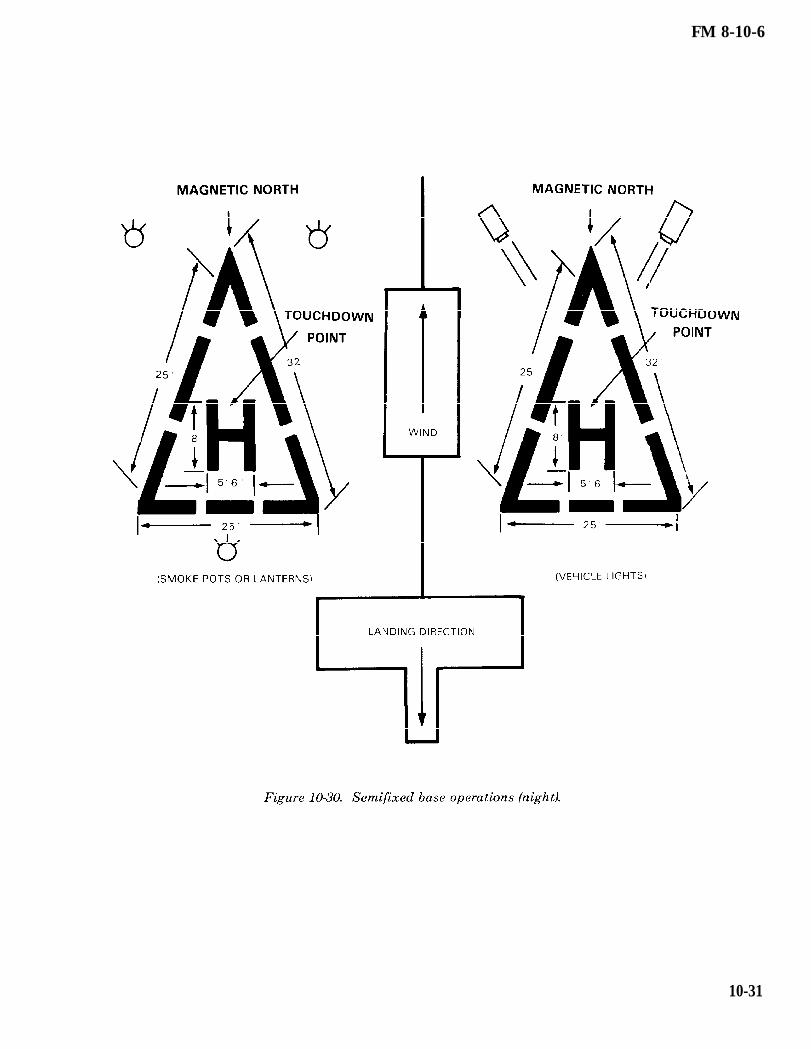
d. Identifying the Landing Site (Figures10-29 through 10-33).
(1) When the tactical situation permits,a landing site should be marked with the letter “H”or “Y,” using identification panels or otherappropriate marking material. Special care must betaken to secure panels to the ground to preventthem from being blown about by the rotor wash.Firmly driven stakes will secure the panels tautly;rocks piled on the corners are not adequate.
(2) If the tactical situation permits, thewind direction may be indicated by a—
Small wind sock or rag tied tothe end of a stick in the vicinity of the LZ.
Man standing at the upwindedge of the site with his back to the wind and hisarm extended forward.
Smoke grenades which emitcolored smoke as soon as the helicopter is sighted.Smoke color should be identified by the aircrew andconfirmed by ground personnel.
(3) In night operations, the followingfactors should be considered:
(a) One of the many ways to marka landing site is to place a light, such as a chemicallight, at each of the four corners of the usable LZ.These lights should be colored to distinguish themfrom other lights which may appear in the vicinity.A particular color can also serve as one element inidentifying the LZ. Flare pots or other types of openlights should only be used as a last resort. Theyusually are blown out by the rotor downwash.Further, they often create a hazardous glare orreflection on the aircraft’s windshield. The site canbe further identified using a coded signal flash to
the pilot from a ground operator. This signal can begiven with the directed beam of a signal lamp,flashlight, vehicle lights, or other means. Whenusing open flames, ground personnel should advisethe pilot before he lands. Burning material must besecured in such a way that it will not blow over andstart a fire in the LZ. Precautions should be taken toensure that open flames are not placed in a positionwhere the pilot must hover over or be within 3meters of them. The coded signal is continuouslyflashed to the pilot until recognition is assured.After recognition, the signal operator, from hisposition on the upwind side of the LZ, directs thebeam of light downwind along the ground to bisectthe landing area. The pilot makes his approach forlanding in line with the beam of light and toward itssource, landing at the center of the marked area. Alllights are displayed for only a minimum time beforearrival of the helicopter. The lights are turned offimmediately after the aircraft lands.
(b) When standard lightingmethods are not possible, pocket-sized white (forday) or blue (for night) strobe lights are excellentmeans to aid the pilot in identifying the LZ.
(c) During takeoff, only thoselights requested by the pilot are displayed; they areturned off immediately after the aircraft’s depar-ture.
(4) When the helicopter approaches theLZ, the ground contact team can ask the pilot toturn on his rotating beacon briefly. This enables theground personnel to identify the aircraft and con-firm its position in relation to the LZ (north, south,east, or west). The rotating beacon can be turned offas soon as the ground contact team has located andidentified the aircraft. The ground contact teamhelps the pilot by informing him of his location inrelation to the LZ, observing the aircraft’ssilhouette, and guiding the aircraft toward the LZ.While the aircraft is maneuvering toward the LZ,two-way radio contact is maintained and the type oflighting or signal being displayed is described bythe pilot and verified by ground personnel via radio.The signal should be continued until the aircrafttouches down in the LZ.
(5) The use of FM homing procedurescan prove to be a valuable asset, especially to troopsin the field under adverse conditions. Through the
10-29

FM 8-10-6
use of FM horning, the pilot can more accuratelylocate the ground personnel. The success of ahoming operation depends upon the actions of theground personnel. First, ground personnel must beoperating an FM radio which is capable of trans-mitting within the frequency range of 30.0 to 69.95megahertz; then they must be able to gain maxi-mum performance from the radio (refer to appro-priate technical manual for procedure). The range ofFM radio communications is limited to line of sight;therefore, personnel should remain as clear aspossible of obstructions and obstacles which couldinterfere with or totally block the radio signals.Ground personnel must have knowledge of the FMhoming procedures. For example, when the pilotasks the radio operator to” key the microphone,” he
is simply asking that the transmit button bedepressed for a period of 10 to 15 seconds. Thisgives the pilot an opportunity to determine thedirection to the person using the radio.
NOTE
When using FM homing electroniccountermeasures, the possible sitedetection of LZs by means of elec-tronic triangulation presents aserious threat and must be con-sidered.
10-30
FM 8-10-6
10-31

FM 8-10-6
10-32

FM 8-10-6
10-33

FM 8-10-6
10-28. Loading Patients Aboard Rotary-WingAircraft
a. Responsibility for Loading and SecuringThe pilot is responsible for ensuring that the littersquad follows the prescribed methods for loadingand securing litters and related equipment. The finaldecision regarding how many patients may be safelyloaded rests with the pilot.
b. Safety Measures. When loading andunloading a rotary-wing aircraft, certain pre-cautionary measures must be observed. Litterbearers must present as low a silhouette as possibleand must keep clear of the rotors at all times. Thehelicopter must not be approached until a crewmember signals to do so. The litter bearers shouldapproach the aircraft at a 45 degree angle from thefront of the helicopter. If the helicopter is on a slopeand conditions permit, loading personnel shouldapproach the aircraft from the downhill side.Directions given by the crew must be followed, andlitters must be carried parallel to the ground.Smoking is not permitted within 50 feet of theaircraft.
10-29. Loading Patients Aboard the UH-60A Black-hawk Helicopter
a. Interior of the UH-60A Blackhawk Heli-copter. This helicopter, as with the UH-1H/V, has anumber of possible seating or cargo configurations.A major difference in preparing the UH-60A tocarry litters is that a medical evacuation kit must beinstalled. This kit consists of a seat/converter
assembly unit and a litter support unit. The seat/converter assembly provides for three rear-facingseats which allows the medical attendant and crewchief to monitor patients. The litter support unitconsists of a center pedestal which can be rotated 90degrees about the vertical axis for the loading andunloading of patients. The litter support unit hasa capacity of four to six litter patients. The patientscan be loaded from either side of the aircraft. Onlythe upper litter supports in the four-litter configura-tion can be tilted for loading and unloading patients.
NOTE
When the six-litter modification kitis installed, the center pedestal canno longer be rotated.
If litter patients are not being evacuated, amaximum of six ambulatory patients can be seatedon the litter support unit (three on each side). Aseventh ambulatory patient can be seated on a troopseat.
NOTE
Only three litters can be loadedwhen using the internal rescue hoist.
When the medical evacuation kit is installed, anumber of cabin configurations are possible. (SeeTables 10-3 and 10-4.)
10-34

FM 8-10-6
b. Guides for Loading Patients.
(1) Litter patients should be positionedin the helicopter according to the nature of theirinjuries or condition. Personnel aboard the aircraftsupervise the loading and positioning of the pa-tients. Normally, the helicopter has a crew of four.The crew consists of a PC, PI, crew chief, andmedical aidman.
(2) The most seriously injured patientsare loaded last on the bottom pans of the littersupport unit. A patient’s condition, however, mayrequire in-flight emergency medical care (such ascardiopulmonary resuscitation). To facilitate accessto the patient, he should be loaded onto either of thetop pans.
(3) The structuring of the litter supportunit allows patients to receive IV fluids and oxygenin flight. Patients receiving IV fluids can be placedon any of the litter pans, depending on their injuriesor condition.
(4) Patients in traction splints shouldbe loaded last and on a bottom pan.
(5) The UH-60A has the capability to beloaded on both sides simultaneously. Patientsshould be loaded so that upon rotating the littersupport, the patient’s head will be forward in thecabin. To accomplish this, patients loaded on theleft side of the aircraft should be loaded head firstand patients loaded on the right side of the aircraftshould be loaded feet first (left and right sides are
determined from the position of the PC’s seat, look-ing forward.) When the six-litter configuration isused, the fifth and sixth litter patients are loadedwith the carousel in the fly position. The patients’heads should face toward the front of the aircraft.
c. Installing Litter Pan Supports. Eachlitter support is attached to the center pedestal bytwo end pivot shafts and by two T-shaped fittings.These fittings and shafts allow for the removal,interchange, or repositioning of the supports. Thereare five pivot shaft support holes at both ends onthe right and left side of the center console. Behindthe holes are support rollers for the pivot shafts.From top to bottom, the top hole is provided for theupper litter in the six litter configuration. Thesecond hole is for the upper litter support of a four-litter configuration. These end holes line up with acentral pivot hole, which accommodates a centralpivot shaft on the litter support. Only this litterposition allows midposition pivoting for loading orunloading. The third hole is for the center litter ofthe six-litter configuration. The fourth hole is usedwhen installing the litter support as a seat forevacuating ambulatory patients. The fifth hole isused for the lower litter support in the four-litterconfiguration. The third, fourth, and fifth positionsdo not provide a tilt function.
(1) Lower litter support installation.Before installing, each center pivot shaft must beretracted and unlocked. The center pivot shafthandle must be secured in the handle retainer. Endpivot handles must be in the tilt position.
10-35

FM 8-10-6
(a) Engage T-bars on litter sup-port with split retention fittings at the bottom ofthe pedestal.
(b) Line up the end pivot shaftswith holes. Disengage the pivot shaft lever locksand move the end pivot shaft lever toward the ped-estal. The pivot shaft is, then, fully inserted into thepivot shaft holes on the pedestal and the handle lockis engaged.
(c) Repeat step (b) for the otherend of litter support.
(2) Upper litter support installation.Before installing, each center pivot pin must beunlocked and retracted. The handle is then dis-engaged from its retainer. The end pivot handlesmust be in the tilt position.
(a) Tilt the outer edge of littersupport slightly down and engage the T-bars intosplit retention fittings at the second support holefrom the top of pedestal.
(b) Raise the outer edge of thelitter support until the support is level.
(c) Insert the end pivot shaft intothe pedestal by pulling on the pivot shaft lever lockand moving the lever toward pedestal until endpivot shaft engages partway in end pivot supporthole.
(d) Turn the center pivot shaftlock handle counterclockwise until it is horizontal.
(e) Push the center pivot shafttoward the pedestal until the shaft is fully insertedinto the center pivot shaft hole. The opposite end ofthe litter support should be raised or lowered toalign the center shaft on the support with the centerhole on pedestal.
(f) Turn the center pivot lock leverclockwise to the horizontal position.
(g) Repeat step (c) above for theother end of litter support. Now slide both end pivotshafts in fully by moving the pivot lever lock handleto engaged position.
10-36
(3) Upper litter support relocation forsix-litter configuration.
(a) Remove the litter support fromthe second support hole from the top of the pedestal.The removal of the litter support is the reverse of itsinstallation. Before relocation, each center pivot pinmust be locked and the handles must be secured inthe handle retainer.
(b) Line up the end pivot shaftswith the top support holes. Then fully insert andengage the handle lock.
(c) Repeat steps (a) and (b) abovefor other end of litter support.
(4) Middle litter support installation forsix-litter configuration.
(a) Remove the litter support fromthe fifth (bottom) support hole. The removal of thelitter support is the reverse of its installation.
(b) Align the end pivot shafts withthird support hole from top of pedestal to relocate it.Then fully insert and engage handle lock.
(c) Repeat steps (a) and (b) abovefor other end of litter support.
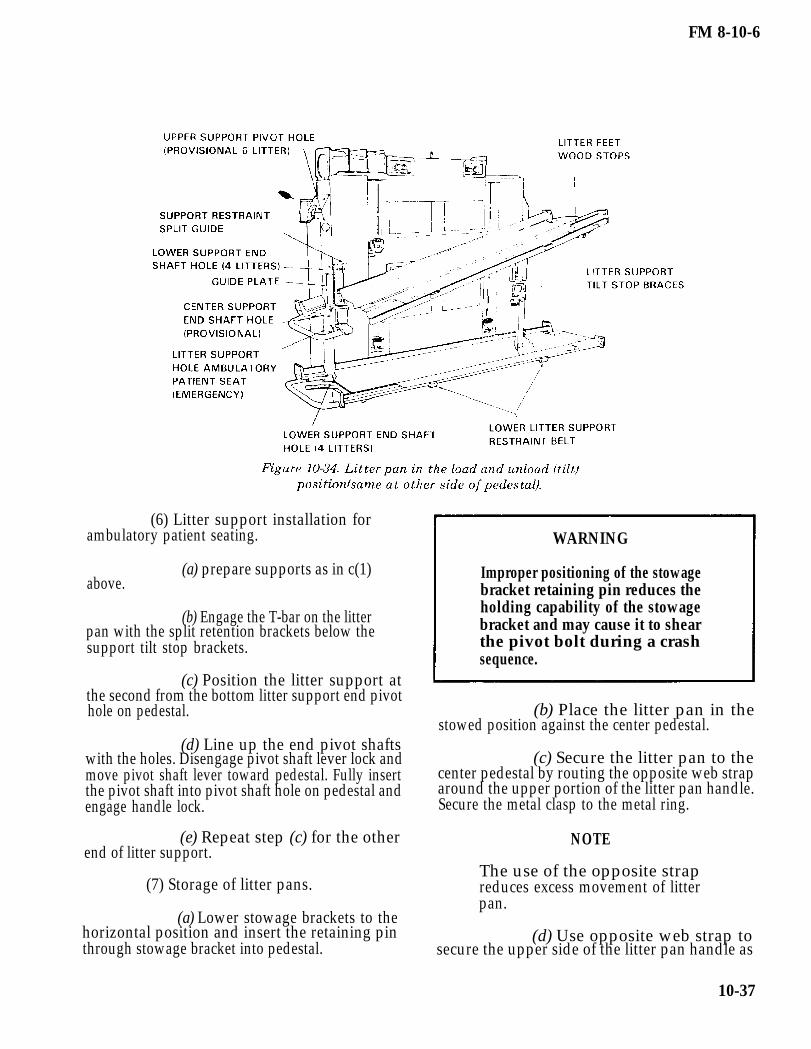
(5) Bottom litter support installationfor six-litter configuration. To complete the six-litter configuration, the modification kit is required.The kit consists of a tube assembly and a restraintassembly for each side.
(a) Insert the restraint assemblyusing the plate quick disconnect fittings into theproper quick attachment fittings on the cargo floor.Pull upon the restraint assembly to check for secureinstallation.
(b) Attach tube assembly longi-tudinally to the proper tie down restraint rings onthe cargo floor. Ensure that the restraint rings areproperly secured to the bracket tube support withthe attached pin (Figure 10-34).
(c) Repeat steps (a) and (b) abovefor the other end of the litter support.
FM 8-10-6
(6) Litter support installation forambulatory patient seating.
(a) prepare supports as in c(1)above.
(b) Engage the T-bar on the litter pan with the split retention brackets below thesupport tilt stop brackets.
(c) Position the litter support atthe second from the bottom litter support end pivothole on pedestal.
(d) Line up the end pivot shaftswith the holes. Disengage pivot shaft lever lock andmove pivot shaft lever toward pedestal. Fully insertthe pivot shaft into pivot shaft hole on pedestal andengage handle lock.
(e) Repeat step (c) for the otherend of litter support.
(7) Storage of litter pans.
(a) Lower stowage brackets to thehorizontal position and insert the retaining pinthrough stowage bracket into pedestal.
WARNING
Improper positioning of the stowagebracket retaining pin reduces theholding capability of the stowagebracket and may cause it to shearthe pivot bolt during a crashsequence.
(b) Place the litter pan in thestowed position against the center pedestal.
(c) Secure the litter pan to thecenter pedestal by routing the opposite web straparound the upper portion of the litter pan handle.Secure the metal clasp to the metal ring.
NOTE
The use of the opposite strapreduces excess movement of litterpan.
(d) Use opposite web strap tosecure the upper side of the litter pan handle as
10-37

FM 8-10-6
described in step (c) above, while the same side webstrap is used to secure the bottom side of the storedlitter pan handle.
(e) Remove the stowed litter pansby reversing steps (a)–(d) above.
d. Loading of Upper Litters. For ease ofloading, the upper litter pans may be tilted. Upperlitter pans are supported by a center pivot shaft andtwo end pivot shafts, one at each end of the litterpan. To tilt the upper support for the loading andunloading of litter patients, the center shaft remainslocked to the pedestal and the end shafts are dis-engaged for support pivoting.
NOTE
This system was designed to pivotabout the center shaft allowingeither end to be tilted downward.Although the supports may be piv-oted at either end, more effort isrequired when a loaded litter isinstalled.
e. Loading and Securing Patients.
(1) In loading four litter patients with afour-man litter squad, the litters are loaded from thetop to bottom. The sequence for loading litters fromone side of the aircraft with the carousel turned is
upper right, upper left, lower right, and then lowerleft. To load litters from both sides of the aircraftsimultaneously, the sequence is upper then lower(Figure 10-35).
(a) The litter support unit is ro-tated 90 degrees clockwise to receive the litterpatients. The flight crew lowers the top pan toaccept the litter and stands by to assist. This isaccomplished as the litter squad approaches theaircraft.
(b) The litter squad moves into thesemioverhead carry, lifting the litter just highenough for the litter stirrups of one end to slide ontothe litter pan. The litter squad slides the litterforward. The flight crew member guides and assiststhe litter squad, until the litter stirrups of both endsare secured on the pan. The litter squad departs asthe flight crew member raises the pan back to itsupright position and secures it. The flight crewmember fastens the litter straps attached to thelitter support assembly.
(c) After the first litter is loaded,the squad leaves the aircraft as a team to obtainanother litter patient. The second, third, and fourthlitters are loaded in the same manner, except thatthe bottom pans are not tilted to receive patients.
(d) After having loaded four litterpatients, the litter support unit is rotated 90degrees counterclockwise and locked in the in-flightposition. The cargo doors must be closed for flight.
10-38

FM 8-10-6
(2) The loading of six litter patientsrequires the repositioning of the litter support priorto loading. The loading procedure remains the sameas the four-litter configuration except for thefollowing:
(a) The top litter support nolonger tilts. This necessitates overhead loading andmay require additional assistance.
(b) After four litters are loaded,the pedestal must be rotated back to the lockedposition. The restraint and tube assembly modifica-tion kit is then installed. The last two Iitters are sideloaded between the restraints, with the patients’heads toward the front of the aircraft. They aresecured.
WARNING(3) When the aircraft is to receive a
mixed load of litter and ambulatory patients, onetop pan of the litter support is removed and reposi-tioned just above the bottom pan on the same side.The aircraft can now accommodate two or threelitter and four ambulatory patients (Figure 10-36).
(a) The litter support unit is ro-tated clockwise to receive the litter patients, exceptfor the third litter in the six-litter configuration. Thelitters are loaded as described in paragraph e (1)above. Upon loading and securing the litter pa-tients, the litter support unit is rotated counter-clockwise to the in-flight position. The third litter isthen loaded when the six-litter configuration is used.
(b) Ambulatory patients are es-corted to the aircraft by ground personnel. They areassisted into their seats and secured with the seatbelts attached to the litter support unit.
(c) The cargo doors are now closedfor flight.
To prevent further injury to patients,all end support pins of the installedlitter pans must be in the lockedposition for flight.
f. Unloading Patients. The aircraft isunloaded in the reverse order of the loading pro-cedure. The pans are normally unloaded bottom panfirst, then top, to ensure that the most seriouslyinjured patients are unloaded first.
160-9230-94–8
10-30. Loading Patients Aboard the UH-lH/VIroquois Helicopter
a. Interior of the UH-IH/V IroquoisHelicopter. This helicopter has several litter and
10-39

FM 8-10-6
seating configurations. A change, to meet opera-tional requirements, can be made from one config-uration to another within a few minutes. Facilitiesfor carrying a tier of three litters loaded lengthwisein the aircraft are located on each side of thehelicopter cargo compartment (Figure 10-37). Thisgives the helicopter a maximum litter capacity ofsix or a total of nine ambulatory patients. This
configuration is normally used in rear areas to movelarge numbers of stable patients. The normal config-uration for the aircraft is three litter patients loadedcrosswise and four ambulatory patients. The maxi-mum load the helicopter can lift must be considered.This load capacity varies with the altitude andtemperature. The pilot advises the personnel on theground of his load capacity.
b. Guides for Loading Patients. Patients arenormally loaded from the top tier down to thebottom tier, with the most seriously injured loadedlast.
(1) Litter patients should be positionedin the helicopter according to the nature of theirinjuries or condition. Personnel aboard the heli-copter supervise the loading of the aircraft.
(2) The most seriously injured patientsare placed in the bottom litter tiers to permit in-flight care.
(3) Litter patients receiving IV fluidsshould not be positioned on the top row of litter tiers
10-40
but should be placed as low as possible in the litterrack.
(4) Patients in Hare traction splintswith splint supports and footrests must be loadedlast and placed directly on the floor of thehelicopter.
c. Loading and Securing Patients.
(1) In loading six litter patients with afour-man litter squad, the litters are loaded fromboth sides of the aircraft and from top to bottom.Figures 10-38 and 10-39 illustrate procedures forloading the right side. Figure 10-40 illustratesprocedures for loading the left side.

FM 8-10-6
(2) When the helicopter is equipped formixed loading (Figures 10-41 through 10-43), threelitters are loaded crosswise and four ambulatorypatients are loaded in the side seats.
(a) When loading from the left, thelitter squad moves to the side of the helicopter withthe litter perpendicular to the cargo compartment;then the squad moves into a litter post carry.Bearers numbers 1 and 3 give their litter handles tothe crew members who place the handles in the littersupport brackets on the far side of the aircraft.Bearers numbers 2 and 4 secure the foot of the litter.
(b) After the first litter is loaded,the squad leaves the helicopter to obtain anotherlitter patient. The second and third litters are loadedin the same way as the first one. After the threelitter patients are loaded, the ambulatory patientsare taken to the aircraft and directed to their seats.
d. Unloading Patients. The aircraft isunloaded in the reverse order of loading. The tiersare unloaded from bottom to top on one side andthen on the other side. At the unloading command,the litter squad moves to the helicopter and thebearers take their proper places at the litter. Thesquad then performs its duties in the reverse orderof loading.
10-41

FM 8-10-6
Section IV. UNITED STATES ARMY NONMEDICAL AIRCRAFT
10-31. General
The US Army has both fixed-wing and rotary-wingaircraft. These aircraft are employed in both the CZand COMMZ.
10-32. Army Fixed-Wing Aircraft
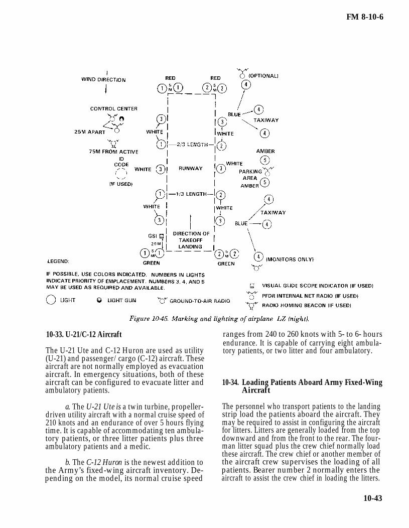
The capability of Army fixed-wing aircraft to landon and take off from selected small, unpreparedareas permits the evacuation of patients from AOswhich would be inaccessible to larger aircraft. These
aircraft can fly slowly and maintain a high degree ofmaneuverability. This capability further enhancestheir value in forward areas under combat condi-tions. Army fixed-wing aircraft are limited in speedand range as compared with larger transport-typeaircraft. When adequate airfields are available(Figures 10-44 and 10-45), fixed-wing aircraft maybe used in forward areas for patient evacuation. Thisis a secondary mission for these aircraft which willbe used only to augment dedicated air ambulancecapabilities. (Field Manual 1-300 discusses airfieldoperations.)
10-42
FM 8-10-6
10-33. U-21/C-12 Aircraft
The U-21 Ute and C-12 Huron are used as utility(U-21) and passenger/cargo (C-12) aircraft. Theseaircraft are not normally employed as evacuationaircraft. In emergency situations, both of theseaircraft can be configured to evacuate litter andambulatory patients.
10-34.
a. The U-21 Ute is a twin turbine, propeller-driven utility aircraft with a normal cruise speed of210 knots and an endurance of over 5 hours flyingtime. It is capable of accommodating ten ambula-tory patients, or three litter patients plus threeambulatory patients and a medic.
b. The C-12 Huron is the newest addition tothe Army’s fixed-wing aircraft inventory. De-pending on the model, its normal cruise speed
ranges from 240 to 260 knots with 5- to 6- hoursendurance. It is capable of carrying eight ambula-tory patients, or two litter and four ambulatory.
Loading Patients Aboard Army Fixed-WingAircraft
The personnel who transport patients to the landingstrip load the patients aboard the aircraft. Theymay be required to assist in configuring the aircraftfor litters. Litters are generally loaded from the topdownward and from the front to the rear. The four-man litter squad plus the crew chief normally loadthese aircraft. The crew chief or another member ofthe aircraft crew supervises the loading of allpatients. Bearer number 2 normally enters theaircraft to assist the crew chief in loading the litters.
10-43

FM 8-10-6
10-35. The CH-47 (Chinook) Helicopter
a. The CH-47 (Chinook) helicopter (Figure10-46), has a capacity of 24 litter patients, or 31ambulatory patients, or a combination of litter andambulatory patients. The aircraft’s overall size androtor blade diameter make it unsuitable for use insmaller or more confined areas.
b. The CH-47 helicopter should not bebrought into a LZ that is smaller than 40 meters indiameter.
10-36. Loading Patients Aboard the CH-47(Chinook) Helicopter
a. Interior of the CH-47 (Chinook) Heli-copter.
(1) This helicopter’s maximum capacityis 24 litter patients or 31 ambulatory patients. The31 ambulatory patients are seated in the ten three-man seats and the one one-man seat as shown inview A of Figure 10-47. The two one-man seats areused by crew members.
(2) When carrying 24 litter patients, theseats are replaced with six tiers of litters, four littershigh. The two one-man seats in the rear sectionshould remain in place for the crew members. Theone-man seat at the left front may also be left inplace provided it is needed.
(3) The combinations of litter andambulatory patients the CH-47 helicopter is capableof accommodating are provided in Table 10-4.
b. Litter Support Kits. These kits areavailable for use in adapting the helicopter’s interiorto evacuate litter patients. These kits containtwelve litter poles, stored in the front of the cargocompartment and twelve litter straps, stored inoverhead recesses. The poles contain safety attach-ments for securing them along the side walls of thecompartment. The pull-down straps on the aisle sideare secured to floor studs. Permanently attached toeach litter pole and each strap are four litter supportbrackets with locking devices for securing litterhandles in place. It is not necessary to remove theseats before adapting the compartment for litterpatients. The seats can be folded against the walland strapped in place.
c. Loading of Litter Patients. The loading oflitter patients aboard the CH-47 helicopter is similarto loading patients aboard the UH-1H/V air ambu-lance except the litter squad is not assisted by thecrew members. In a two-man carry, the litter squad
10-44

FM 8-10-6
carries each litter patient through the lowered rear requiring in-flight medical care should be positioneddoor and ramp to the litter rack where he is to be to facilitate this care. If the helicopter is to beplaced. The squad then moves into a four-man carry loaded with a combination of litter and ambulatoryand places the litter patient into the appropriate patients, the litter patients should be positioned totier. The litter racks should be loaded from front to the rear of the ambulatory patients wheneverrear and from top to bottom. Litter patients possible.
Section V. UNITED STATES AIR FORCE AIRCRAFT
10-38.
10-37. General
Most USAF cargo aircraft can be used foraeromedical evacuation. The aircraft used for theforward airlift movement of troops and suppliesmay be reconfigured for the aeromedical evacuationmission on the return flight (provided proper equip-ment is available).
Types of Air Force Transport Aircraft andUnits
a. The C-130 Hercules Transport. Thisaircraft is a four-engine, turbo-propeller drivenaircraft with a pressurized, air-conditioned cabinand a self-contained loading ramp. In the normalpatient configuration, this aircraft can accommo-date 50 litter and 27 ambulatory patients. This can
be varied for as many as 70 litters with no ambu-latory patients, or 85 ambulatory patients with nolitters. These figures represent maximum patientcapacity and would not be used routinely. Themedical crew is normally provided by the USAF. Itconsists of two flight nurses and three aeromedicalevacuation technicians. The C-130 can land on andtake off from short runways. It can also be used onlanding strips such as those found in forward baseoperations. Its normal use is within a TO for tacticaland assault airlift. The C-130 can also be used forstrategic airlift missions, if required.
b. The C-9A Nightingale. This aircraft is aT-tailed aeromedical airlift with two jet engines anda pressurized, air-conditioned cabin. The Nightin-gale is the military version of the DC-9 airliner with
10-45

FM 8-10-6
an interior specifically designed for in-flight patientcare. It is the only aircraft in the USAF inventorythat is dedicated to the medical evacuation mission.It has a self-contained patient enplaning ramp andcan accommodate 40 litter patients, 40 ambulatorypatients, or a combination of both. The normalconfiguration is for 15 litter and 24 ambulatorypatients. The medical crew normally consists of twoflight nurses and three aeromedical evacuationtechnicians.
10-39.c. The C-141 Starlifter. This aircraft is a
four-engine, jet cargo transport aircraft. The cabinis pressurized, heated, or cooled, as required. Theambulance bus may be backed to the ramp at thetail of the aircraft for easy enplaning of litterpatients. The C-141 can accommodate 103 litterpatients, 147 ambulatory patients, or a combinationof both. Maximum capacity is not routinely used, ascrowding detracts from patient comfort. The usualmedical crew is two flight nurses and three aero-medical evacuation technicians. The C-141 is usedfor all missions of the MAC’s Strategic AeromedicalEvacuation System. With the backhaul capacity,these intercontinental cargo aircraft provideaeromedical evacuation from a TO to CONUS.
d. The C-5 Galaxy. The C-5 is the UnitedState’s largest aircraft. The aircraft is normally acargo mover, with a payload of over 200,000 pounds.If required, it could carry up to 70 ambulatorypatients in its upper-aft passenger compartment inaddition to its cargo load.
e. The C-17A. This aircraft will consist ofwall seating with safety belts for ten medicalpersonnel, 44 ambulatory patients, stanchionprototypes to accommodate 48 litter patients, andnecessary medical equipment needed for in-flightpatient treatment. Approximate position of oxygenrecharger hoses will be marked on the internal cargocompartment wall.
f. Air Force. The USAF has functionallyorganized units specifically designed to performaeromedical evacuation. There are two basic typesof units. Either type of organization can provide forthe operation of the AECC, ASFs, in-flight medicalcare teams, and liaison personnel.
(1) Aeromedical aircraft units (flights,squadrons, groups, or wings) combine personnel for
operation of the aircraft and medical personnel inthe same organization.
(2) Aeromedical evacuation units(flights, squadrons, or groups) are strictly medicalorganizations. These units possess no organic air-craft; they rely on the backhaul capability of cargoaircraft.
AeromedicaI Evacuation (AE) Civil ReserveAir Fleet Aircraft (CRAF)
a. The Boeing-767 (B-767). The Boeing 767 isa wide-body, long-range, twin-engine aircraft. Intimes of national conflict, the aircraft can bemodified with predesigned ship sets to accommo-date up to 111 litters. Once configured, the aircraftwill be flown in a strategic role, evacuating patientsfrom the TO to CONUS. The medical crew composi-tion will consist of two standard crews (four flightnurses and six aeromedical technicians).
b. The McDonnell Douglas-80 (MD-80). TheMD-80 is a single-engine, short-range aircraft whichwill be used in CONUS for patient redistribution.When configured in an aeromedical role, the MD-80will carry up to 45 litters. The medical crewcompliment will consist of two nurses and threeaeromedical technicians.
10-40. Preparing Aircraft to Receive Patients
The aircraft crew is responsible for preparations toreceive litter patients. Before the patients areloaded, the medical crew director inspects the air-craft to ensure that the required supplies and equip-ment are available and in operating order. The itemsinspected include—
Accessories, such as litter straps, clamps,stanchions, hot cups, and spare flashlights.
Rigging to ensure security.
Medical chests, water and coffee jugs,walk-around oxygen bottles, trash receivers, andother movable items to ensure that they are prop-erly fastened to withstand flying conditions andthat they constitute no hazard to occupants of theaircraft.
10-46

FM 8-10-6
Cabin-to-cockpit communications systemto ensure that it is operative. This is accomplishedby making a communications check with the pilot.
Patients’ survival and other equipmentas it is loaded on the aircraft to ensure conformitywith the existing instructions for the particularaircraft.
10-41. Developing the Loading Plan
a. The plan for loading patients aboard alarge transport aircraft depends upon the capacityof the aircraft, the length of the flight, and thenumber of litter and ambulatory patients to betransported. Transport aircraft carry litters in tiers,normally three or four litters high. In developing aloading plan, the objective is to place each litterpatient in the space which provides the most com-fort for him without detracting from the comfort ofother patients. It is necessary to consider—
Diagnosis.
Preflight preparation or medicationto be given the patient.
Point where he is to be unloaded.
Amount of care required duringflight.
b. The following factors should beconsidered when developing the loading plan:
Patients in plaster casts or splintsmust be placed on the side of the aircraft whichwould make the injured limb accessible for treat-ment.
Patients with certain conditionsrequiring travel in a sitting or semiprone positionrequire the same amount of space as two litters.
Female patients should be segre-gated as much as possible from male patients.
Patients requiring bedpans, IVinfusions, special treatment, or dressings duringflight should be placed in the middle tier where theyare more accessible for care.
Patients who are unable to helpthemselves should, if possible, be located near themain cargo door to facilitate their exit in event of anemergency.
Patients suffering mental dis-turbances should be located in positions that affordmaximum observation.
Patients with a diagnosis oftuberculosis or other communicable disease shouldbe loaded in rear litter tiers.
Patients who are restless, such asthose with head injuries, or those who areunconscious must be placed on the bottom tiers.
Patients with coughs and thosesubject to airsickness should be placed on thebottom tier and positioned at the downwind end ofthe normal ventilation flow.
After the patients are loaded, theirpersonal effects should be stowed in the baggagecompartment or the rear portion of the cabin.
A preflight briefing should be givento all patients. The medical crew director isresponsible for ensuring that this briefing isconducted before each flight. The briefing should becomplete and conducted in such a way as not toalarm patients who are flying for the first time.
10-47