ev3000 operators manual - ampacampac.net/uploaded/manuals/man2789-10_ev3000_inst... · ev3000...
TRANSCRIPT

EV3000
Occupant Warning & Intercommunications System
(3 Wire / S004)
Installation & Commissioning
MAN2789-10

Table Of Contents Page No
1 Non Disclosure Agreement ......................................................................... 1
2 Certification Information .............................................................................. 2
3 Equipment Manufacturing Details .............................................................. 2
4 Purpose ......................................................................................................... 3
4.1 Scope ................................................................................................................... 3
4.2 References ........................................................................................................... 3
4.2.1 EV3000 System Manuals: ..................................................................... 3
4.2.2 Australian Standards ............................................................................ 3
4.3 System Overview ................................................................................................. 3
5 System Description ...................................................................................... 4
5.1 Occupant Warning System ................................................................................. 4
5.2 Occupant Intercommunication System .............................................................. 4
6 ECP & Main Equipment Layout ................................................................... 5
7 OWIS Components ....................................................................................... 6
7.1 The Emergency Control Panel ............................................................................ 6
7.2 Ancillary Components ECP ................................................................................ 6
7.2.1 MICROPHONE ....................................................................................... 6
7.2.2 Master OIS Handset And All Call Switch ............................................. 6
7.2.3 Emergency Alarm Initiating Device (EAID) .......................................... 6
8 OWS, OIS And ECP Operation .................................................................... 7
8.1 Emergency Control Panel ................................................................................... 7
8.1.1 Operating Instructions ......................................................................... 7
8.1.2 Automatic / Manual / Isolate Key Switch ............................................. 8
8.1.3 All Call Facility ...................................................................................... 9
8.1.4 Buzzer ................................................................................................... 9
8.1.5 Buzzer Mute / Alarm Acknowledge ...................................................... 9
8.1.6 Master Reset ....................................................................................... 10
8.1.7 Lamp Test Facility .............................................................................. 10
8.1.8 System Test Facility ........................................................................... 10
8.1.9 System Status Indicators ................................................................... 10
8.1.10 Zone Status (Fault Diagnostics) ........................................................ 11
8.2 OWS Zone Control Panel .................................................................................. 11
8.2.1 OWS Zone Control Switches And Indicators .................................... 11
8.2.2 OWS Zone Fault .................................................................................. 11
8.2.3 Alarm Origin........................................................................................ 11
8.2.4 Zone Labelling .................................................................................... 12
8.3 OIS Control Panel .............................................................................................. 12
8.3.1 WIP Select Switch ............................................................................... 12
8.3.2 WIP Select Indicator (Red) ................................................................. 12
8.3.3 WIP Call Buzzer .................................................................................. 12

8.3.4 Zone Cleared Switch .......................................................................... 12
8.3.5 WIP Fault Indicator (Amber) ............................................................... 12
8.4 OIS System Operation ....................................................................................... 12
8.4.1 WIP Calling ECP ................................................................................. 12
8.4.2 Conference Call .................................................................................. 13
8.4.3 Completing the Call by the WIP ......................................................... 13
8.4.4 Completing the Call by the ECP ......................................................... 13
8.4.5 ECP Calling WIP ................................................................................. 13
8.4.6 ECP To All WIPS (ALL CALL) ............................................................. 13
8.4.7 Completing The All Call...................................................................... 13
8.4.8 OIS Controlling ECP ........................................................................... 13
8.4.9 Zone Labelling - Refer to Appendix A ................................................ 13
8.4.10 Remote Paging Console ..................................................................... 14
8.5 Main Equipment Description............................................................................. 15
8.5.1 Common Board Frame ....................................................................... 15
8.5.2 Signal/Speech Generator ................................................................... 16
8.5.3 Signal Generator Settings .................................................................. 16
8.5.4 Standby / Speech Generator .............................................................. 16
8.5.5 Microphone / BGM Mixer Board ......................................................... 17
8.5.6 Standby Microphone / BGM Mixer Board .......................................... 17
8.5.7 FACP Input CPU Board ...................................................................... 17
8.5.8 Main CPU ............................................................................................ 17
8.5.9 Amplifier Rack Frame ......................................................................... 18
8.5.10 40 Watt Amplifier ................................................................................ 18
8.5.11 120 Watt Amplifier .............................................................................. 19
8.5.12 Warden Intercom Control Frame ....................................................... 20
8.5.13 OIS Control CPU ................................................................................. 20
8.5.14 OIS Selector Board ............................................................................. 20
8.5.15 EAID Line Card ................................................................................... 20
8.5.16 Fan Module ......................................................................................... 20
8.5.17 Power Supply ...................................................................................... 21
8.5.18 Fault Relay .......................................................................................... 21
9 Installation .................................................................................................. 22
9.1 Unpacking And Inspection ................................................................................ 22
9.2 Anti-Static Precautions ..................................................................................... 22
9.3 Working On The System ................................................................................... 22
9.4 Cabinet Installation ........................................................................................... 22
9.4.1 Surface Mount .................................................................................... 22
9.4.2 Recess Mount ..................................................................................... 22
10 Connecting The EV3000 ............................................................................ 23
10.1 FACP Input Connections (Individual inputs) .................................................... 23
10.1.1 Connections........................................................................................ 23
10.1.2 Fusing ................................................................................................. 23
10.1.3 Address Setting .................................................................................. 23
10.2 Common FACP Input Connections .................................................................. 24
10.3 SECP MIC, BGM And SECP OIS Handset Input Connections ......................... 24

10.3.1 Connections........................................................................................ 24
10.4 100V Line Speaker Connections ....................................................................... 25
10.4.1 Connections........................................................................................ 25
10.4.2 Fusing ................................................................................................. 25
10.5 Visual Indicators Output Connections ............................................................. 26
10.5.1 Connections........................................................................................ 26
10.5.2 Fusing ................................................................................................. 26
10.6 WIP/EAID Extension Connections .................................................................... 28
10.6.1 Connections........................................................................................ 28
10.7 MECP To SECP Data Connections ................................................................... 29
10.7.1 Connections........................................................................................ 29
10.8 CN5 + CN6 Power Supply to Board .................................................................. 29
10.8.1 Fusing ................................................................................................. 29
10.9 Mains Connection ............................................................................................. 30
11 Devices........................................................................................................ 31
11.1 Speakers ............................................................................................................ 31
11.2 Visual Warning Devices .................................................................................... 32
11.3 Warden Intercommunication Point (WIP) ......................................................... 33
11.4 EAID ................................................................................................................... 34
12 SECP And Remote Console Connections ................................................ 35
13 Placing System Into Operation ................................................................. 36
13.1 System Power Up Sequence ............................................................................. 36
13.2 Time Out Setting For Automatic Evacuation Sequence .................................. 37
14 Faults........................................................................................................... 38
14.1 Fault Indicators.................................................................................................. 38
14.2 Fault Diagnostics .............................................................................................. 38
15 Trouble Shooting ....................................................................................... 39
16 Appendix A: Zone Labelling ..................................................................... 41
17 Appendix B: Compatible Devices ............................................................ 42
18 Appendix C: Amplifier Addressing .......................................................... 43
19 Appendix D: Amplifier Strapping ............................................................. 44
20 Appendix E: Typical EV3000 16 & 29 Unit Wiring ................................... 45
21 Glossary Of Terms ..................................................................................... 47
22 Definitions ................................................................................................... 48

Page 1
EV3000 INSTALLATION & COMMISSIONING
1 Non Disclosure Agreement
This contract has been entered into by the user of this document, person or company (hereafter called the Trader) and AMPAC Technologies (hereafter called AMPAC) of 7 Ledgar Rd, Balcatta, WA 6021, Western Australia under terms and conditions as specified hereunder.
Whereas Ampac and the Trader for their mutual benefit and pursuant to a working relationship which may be established, anticipate that Ampac will disclose in the form of this document, information of a secret, or confidential or proprietary nature (hereinafter collectively referred to as Proprietary Information).
Whereas Ampac desires to ensure that the confidentiality of any Proprietary Information is maintained in accordance with the terms of this Agreement;
NOW, THEREFORE, in consideration of the foregoing premises, and the mutual covenants contained herein, the Trader hereby agrees as follows:
1. The Trader shall hold in trust and confidence, and not disclose to any person outside its organisation, any Proprietary information which is disclosed to the Trader by Ampac under this Agreement. Proprietary Information disclosed under this Agreement may be used by the Trader only for the purpose of carrying out work on or with Ampac supplied equipment and may not be used for any other purpose whatsoever.
2. The Trader shall disclose Proprietary Information received by Ampac under this Agreement to persons within its organisation only if such persons are legally bound in writing to protect the confidentiality of such Proprietary Information.
3. The undertakings and obligations of the Trader under this Agreement shall not apply to any Proprietary Information which:
(a) is disclosed in a printed publication available to the public, is described in patent anywhere in the world, or is otherwise in the public domain at the time of disclosure;
(b) is generally disclosed to third parties by Ampac without restriction on such third parties;
(c) is shown by the Trader to have been in its possession prior to the receipt thereof from Ampac;
(d) is approved for release by written authorisation of Ampac; or
(e) is not designated by Ampac in writing or by appropriate stamp or legend to be of a secret, confidential or proprietary nature.
4. This Agreement will be binding upon and inure to the benefit of the parties hereto, and their respective successors and assigns.
5. This Agreement, and all rights and obligations hereunder, shall expire on the 10th anniversary of the date of issue of this document.
These terms are accepted by the Trader on receipt and retention of this document.

Page 2
EV3000 INSTALLATION & COMMISSIONING
2 Certification Information
EV3000
OCCUPANT WARNING AND INTERCOMMUNICATION SYSTEM
MANUFACTURED BY:
AMPAC Technologies Pty Ltd.
7 LEDGAR RD
BALCATTA
WA 6017
WESTERN AUSTRALIA
PH: 61-8-9242 3333
FAX: 61-8-9242 3334
MANUFACTURED TO: AS2220.1-1989
AS1670.4-2004
SSL CERTIFICATE OF
COMPLIANCE NUMBER: AFP - 603
3 Equipment Manufacturing Details
JOB / SERIAL NUMBER:
MANUFACTURE DATE: / /
(HEAD OFFICE)

Page 3
EV3000 INSTALLATION & COMMISSIONING
4 Purpose
The purpose of this manual is to assist in the installation and operation of the EV3000 Occupant Warning and Intercommunication System (OWIS).
4.1 Scope
The information within this manual is only available to and for the use of personnel engaged in the installation and operation of the EV3000 OWIS.
4.2 References
4.2.1 EV3000 System Manuals:
Document No. M0010WT1 EV3000 OWIS Technical Manual.
Document No. M0010WI1 EV3000 OWIS Installation, Programming and Commissioning Manual.
4.2.2 Australian Standards
AS2220.1-1989 Emergency Warning and Intercommunication systems in buildings Part 1: Equipment Design and Manufacture.
AS1851 Part 10 Maintenance of Fire Protection Equipment, Part 10: Emergency Warning and Intercommunication systems.
AS1670.4-2004 Fire Detection, Warning, Control and Intercom Systems – System Design, Installation and Commissioning. Part 4: Sound Systems and Intercom Systems for Emergency Purposes
4.3 System Overview
The Ampac EV3000 Occupant Warning and Intercommunication System is a microprocessor based OWIS system that complies with Australian Standards AS2220.1 and produces Alert and Evacuation signals compliant with AS1670.4
The OWIS comprises of two sub-systems,
1. Occupant Warning System (OWS)
The prime function of an OWS is to transmit via speakers in evacuation zones, alert signals, evacuation signals and public address clearly and reliably.
The OWS can automatically initiate evacuation procedures or be manually operated as well being used for non-emergency functions, e.g. background music and general PA facilities.
2. Occupant Intercommunication System (OIS).
The OIS is a totally independent intercommunication system provided to communicate on a one to one basis from the Master Emergency Control Panel (MECP) to the individual Warden Intercommunication Points (WIP’s) within the evacuation zones.
The OWS and OIS are collectively referred to as the Occupant Warning and Intercommunication System (OWIS).

Page 4
EV3000 INSTALLATION & COMMISSIONING
5 System Description
5.1 Occupant Warning System
The OWS subdivides the building into evacuation zones. Each evacuation zone has one or more amplifiers and a number of associated speakers. In sections of a building where the background noise is high, visual warning devices may be used in addition to speakers. Each evacuation zone amplifier may be switched by the system to one of four audio channels. These channels are PA, Alert signal, Evacuation signal and Background music (BGM). The BGM channel to each amplifier can be configured on site by jumper links to one of the following sources:
Background music 1 Background music 2 Silence
During non-emergency situations the evacuation zones can have the PA channel or BGM channel switched to allow the OWS to be used for PA facilities or background music. The background music is disabled;
in an emergency situation, if the OWS is manually operated; or if the mains power fails.
The signal generator module (SGM) is responsible for generating the alert and evacuation signals as well as the alert and evacuation verbal messages.
The OWS has two possible types of alarm signal inputs to indicate that an emergency condition is occurring in the building. These are:
Emergency Alarm Initiating Devices (EAID’s) i.e. manual call points Fire Alarm Control Panel (FACP)
These inputs are grouped according to the building evacuation zones. Any number of EAID’s and FACP’s inputs may be assigned to any one building evacuation zones or group of zones.
When an input, i.e. EAID or FACP initiates an alarm signal the OWS, if in automatic mode, will initiate a preset evacuation sequence. The evacuation sequence will sound the Alert / Evac signals to the evacuation zones within the building and activating the visual warning devices (if installed) according to the pre-programmed evacuation sequence. The manual override will cease the pre-programmed evacuation sequence, and output Alert / Evac signals to evacuation zones as dictated via the OWS panel control switches. If the keyswitch is placed back into the Auto position after an evacuation sequence is stopped by use of the keyswitch and no keys were pressed in Manual then the evacuation sequence will be discontinued.
The OWS provides full system status and fault indication facilities.
If the OWS has more than one ECP, one ECP is referred to as the Master Emergency Control Panel (MECP) and the remaining ECP’s are referred to as Secondary Emergency Control Panels (SECP’s).
5.2 Occupant Intercommunication System
The OIS provides an independent communication system between the controlling ECP and a Warden Intercommunication Point (WIP). OIS features are:
The controlling ECP can call individual WIP’s or enter an All Call mode, where all the WIP’s are called simultaneously.
The controlling ECP and up to 5 WIP’s can communicate in a conference mode. Calls to an individual WIP's have full duplex communication. All Call, communication is half duplex from the controlling ECP. Any WIP can call the controlling ECP the call is answered at the controlling ECP at the
operators’ discretion.

Page 5
EV3000 INSTALLATION & COMMISSIONING
6 ECP & Main Equipment Layout
Figure 1: illustrates a typical EV3000 in a 29U floor standing rack equipped with the main equipment, 24 OWS controls and 48 OIS controls.
The standard mechanical construction of the EV3000 is 483mm (19inch) rack mounting frames with EURO Card size plug-in modules.
MICROPHONE
MASTER OISHANDSET WITH ALL CALL SWITCH
D090 PHILIPS
AUXILIARY CONTROL PANEL
OPERATINGINSTRUCTIONSALL CALL PANELAND SYSTEMSTATUS INDICATION
OCCUPANT INTER-COMMUNICATION SELECTIONZONES 1 TO 48
OCCUPANT WARNINGSYSTEM SELECTIONZONES 1 TO 24 EMERGENCY
CONTROL PANEL
COMMON CONTROLFRAME / MAINEQUIPMENT
MAIN EQUIPMENT
BLANK
OIS CONTROL
AMPLIFIER RACK FRAME8 POSITIONS
AMPS 17 TO 24
AMPLIFIER RACK FRAME8 POSITIONSAMPS 9 TO 16
AMPLIFIER RACK FRAME8 POSITIONSAMPS 1 TO 8
FAN PANEL
15 AMP POWER SUPPLY
BATTERY CABINET
MANUAL CALL POINT
Figure 1: ECP and Main Equipment

Page 6
EV3000 INSTALLATION & COMMISSIONING
7 OWIS Components
The OWIS is broken into three components:
1. Master Emergency Control Panel 2. Cabling 3. Devices
The Master Emergency Control Panels can be further broken down into two sections,
1. Emergency Control Panel 2. Main Equipment
7.1 The Emergency Control Panel
The ECP consists of:
A Control Panel which contains the Auto/Manual/Isolate facility, the All Call facility, the common System Status and Zone Status controls and indicators.
An OWS control panel which controls the manual selection of audible signals to the Evacuation zones and an OIS control panel which controls the communication with WIP extensions.
7.2 Ancillary Components ECP
7.2.1 MICROPHONE
The microphone;
is used for the PA facility; has a press to talk (PTT) switch; and is normally disabled unless the ECP is in control, i.e. the key-switch is in the MANUAL position
and its REMOTE ECP IN CONTROL indicator is NOT illuminated.
7.2.2 Master OIS Handset And All Call Switch
Handset and associated cradle (RED).
7.2.3 Emergency Alarm Initiating Device (EAID)
The EAID on the ECP is one of the Alarm inputs for the evacuation zone that corresponds to the section of the building where the ECP is located.

Page 7
EV3000 INSTALLATION & COMMISSIONING
8 OWS, OIS And ECP Operation
The EV3000 ECP has three sections, the;
1. Emergency control panel, 2. OWS control panel; and 3. OIS control panel.
8.1 Emergency Control Panel
The Emergency Control Panel contains the common system controls and indicators and the common OWS controls and indicators and the operating instructions. The layout of the controls on the Master Control Panel is shown below.
ISOLATE AUTOMATIC
MANUAL
E.C.P.IN CONTROL
ALLEVAC
ALLALERT
ALLP.A.
CANCEL
LAMPTEST
SYSTEMTEST
ALARM SYSTEMFAULT
VISUALLINE FAULT
EIADFAULT
AMPLIFIER/SPEAKERFAULT
MICROPHONEFAULT
MODULEFAULT
SYSTEMFAULT
COMMSFAULT
ALARM SYSTEMISOLATED
TONEFAULT
BATTERYISOLATED
BATTERYFAULT
CHARGERFAULT
SYSTEM ONBATTERIES
POWERON
ALL CALL SYSTEM STATUS
ZONE STATUS
EMERGENCY CONTROL PANEL
BUZZERMUTE/ACK
MASTERRESET
Figure 2: Master Control Panel
8.1.1 Operating Instructions
The EV3000 has a set of emergency operating instructions on the facia of the Master Control Panel.
E V 3 0 0 0
EMERGENCY OPERATING INSTRUCTIONSEMERGENCY WARNING SYSTEM (E.W.S.)
1. TO SILENCE AUTOMATIC TONES PLACE KEYSWITCH IN MANUAL POSITION.
2. INDIVIDUAL ZONE OPERATION PUBLIC ADDRESS
3. ALL ZONE OPERATION PRESS REQUIRED 'ALL CALL' SWITCH.4. TO RESTORE E.W.S. TO NORMAL PRESS
EMERGENCY INTERCOMMUNICATION SYSTEM (E.I.S.)1. TO CALL INDIVIDUAL WIP
2. TO ANSWER INCOMING CALL
3. TO TERMINATE CALL
4. TO 'ALL CALL' WIPS
5. TO TERMINATE ALL CALL6. ZONE CLEARED PRESS ZONE CLEARED SWITCH FOR ZONE CLEARED INDICATOR
ON OR OFF. (MASTER WIP HANDSET MUST BE LIFTED).
(FIVE WIPS MAX) LIFT HANDSET, PRESS WIP SELECT SWITCH FORREQUIRED WIP, THEN WAIT FOR WARDEN TO ANSWER THE WIP.
(FIVE WIPS MAX) LIFT HANDSET, PRESS WIP SWITCH WITHFLASHING INDICATOR, INDICATOR WILL GO STEADY.
PRESS WIP SELECT SWITCH WITH STEADY INDICATOROR REPLACE HANDSET ON CRADLE.
LIFT HANDSET, PRESS 'ALL CALL' ON MASTER PHONE, WIPSELECT INDICATORS WILL FLASH, THEN BECOME STEADY AS WIPSARE ANSWERED -CONVERSATION IS FROM MASTER TO WIPS ONLY.REPLACE HANDSET ON CRADLE.
PRESSTHEN PRESS
ALERT SIGNAL EVACUATION SIGNAL
TO CLEAR SELECTION
THEN RETURN KEYSWITCH TO AUTO.
PRESS
PRESSPRESS
PRESS
5. WHEN TESTING FIB, PLACE E.W.S. IN MANUAL.
P.A. SWITCH
SWITCHSWITCH
SWITCH
ALERTEVAC
CANCEL
BUZZER MUTE/ACKMASTER RESET TO CANCEL TONES
BUZZER MUTE/ACK MASTER RESET,
Figure 3: Instructions

Page 8
EV3000 INSTALLATION & COMMISSIONING
8.1.2 Automatic / Manual / Isolate Key Switch
1. Automatic Position
In the Automatic Position the OWS will enter the programmed evacuation sequence when an alarm signal is received from an FACP or EAID.
The switch key is removable only in this position.
A green automatic indicator is illuminated when the switch is in the automatic position.
2. Manual Position
The purpose of this position is to take manual control of the building evacuation, irrespective of the state of the alarm signals. This position also allows routine testing of the building alarm system and OWS.
The automatic initiation of an evacuation sequence is inhibited.
If the OWS has entered the evacuation sequence whilst in the AUTOMATIC position and the OWS is switched to the MANUAL position, the state of the OWS at that instant is held, i.e. each zone's output remains in that state.
If the OWS is then switched back to the AUTOMATIC position without any zone control switches being operated, the automatic evacuation tones will continue as normal but the evacuation sequence remains halted.
If the OWS is switched back to the AUTOMATIC position and the control switches have been operated, the automatic evacuation sequence will not continue. If a new alarm input is received this will override the current state of the zones.
3. Manual Override of SECP's
Where a OWS has more than one ECP, any ECP can take manual control of the OWS by turning the key-switch to the MANUAL position. Only the MECP being switched to the MANUAL position shall override any SECP with its key-switch in the MANUAL position.
Each ECP is fitted with an "REMOTE ECP IN CONTROL" indicator. When an ECP is switched to the MANUAL mode, all other ECP’s in the OWS will illuminate their REMOTE ECP IN CONTROL indicator.
If an SECP is in control and the MECP is switched to MANUAL, the MECP will then take control, its REMOTE ECP IN CONTROL indicator will switch off and the SECP which was previously in control will illuminate its REMOTE ECP IN CONTROL indicator.
When the key-switch at a ECP is in the manual position the alarm system isolated indicator will illuminate steady.
4. Isolate Position
This key-switch position is local to the ECP and will not affect any other ECP's. A red indicator is illuminated when the switch is in this position.
The ECP will not recognise the isolated position if selected from the manual position. When selecting the EV3000 to isolate, the switch must be rotated from automatic, through manual, to isolate position within 1 second. Further more the system must be in an inactive state, i.e. fans are not running, no alarms are present etc.
In this position the control switches and front panel indicators only function locally, with no zone outputs, i.e. speakers and visual alarm devices being activated. The indicators selected in this position will flash. This position is used for training purposes.
If an ECP is in the ISOLATE position, and another ECP is switched to manual, the ECP in the ISOLATE position will illuminate its REMOTE ECP IN CONTROL indicator and the control switch indicators will reflect the status of the OWS, not local control switch selections.
If an ECP is in the ISOLATE position, and the OWS receives an FACP input then the OWS will return to the AUTO state and commence the evacuation sequence. The control switch indicators will reflect the state of the OWS, not the local control switch selections. The ALARM ORIGIN INDICATORS will reflect which zone caused the OWS to enter the evacuation sequence.

Page 9
EV3000 INSTALLATION & COMMISSIONING
8.1.3 All Call Facility
Four control switches, i.e. "ALL OFF", "ALL PA", "ALL ALERT" and "ALL EVAC" provide the ALL CALL facility. The selected audio channel is delivered to ALL the evacuation zones. There are three ALL CALL indicators which reflect the all call selection. These are:
PA ALERT EVAC
The ALL CALL inputs have priority over the OWS Control switches. Turning the ALL CALL facility OFF (All Call 'CANCEL') will return the OWS to its condition before the use of the All Call facility.
8.1.4 Buzzer
The ECP is fitted with an internal buzzer which is activated by the following conditions:
amplifier / speaker line fault visual alarm line fault alarm system fault (FACP, EAID) communications fault (to other ECP’s) system on batteries - local if locally powered, or remote if remotely powered battery fault - local if locally powered, or remote if remotely powered charger fail - local if locally powered, or remote if remotely powered signal generator fail module fault system fault WIP line fault visual line fault EAID line fault microphone pre-amp fail
8.1.5 Buzzer Mute / Alarm Acknowledge
When the BUZZER MUTE button is pressed, all outstanding alarm and fault conditions are acknowledged. All flashing indicators go steady, and the buzzer is muted. For system wide faults, pressing the BUZZER MUTE at any ECP will acknowledge the fault at all ECP’s.
System wide faults are:
amplifier / speaker line fault visual alarm line fault alarm system fault (FACP, EAID) communications fault system on batteries - if all ECP’s remotely powered battery fault - if all ECP’s remotely powered charger fail - if all ECP’s remotely powered signal generator fail / microphone pre-amp fail module fault system fault WIP system fault visual line fault EAID line fault

Page 10
EV3000 INSTALLATION & COMMISSIONING
8.1.6 Master Reset
Master Reset facility is only active when the ECP is in the Manual mode.
When pressed all zone outputs switch to the off channel but only if there are NO unacknowledged EAID or FACP alarm signals in the OWS.
8.1.7 Lamp Test Facility
The LAMP TEST facility causes all the front panel indicators (on the master control panel only) to illuminate and the audible buzzer operates for 3 seconds then resets.
The following indicators are not included;
1. Mains On, 2. System on Batteries, 3. Charger Fault, 4. Battery Fault and 5. Battery Isolated
The LAMP TEST is invoked by momentarily pressing the LAMP TEST button.
8.1.8 System Test Facility
This facility allows the testing of the evacuation sequence fitted without broadcasting signals.
To invoke a test of the sequence:
1. Place keyswitch into ISOLATE position 2. Press SYSTEM TEST 3. Press the CANCEL button for the OWS zone input to simulate an alarm. 4. System should indicate the sequence but not output any audio signals. 5. To restore system to normal return keyswitch to AUTO.
The LAMP TEST is invoked by momentarily pressing the LAMP TEST button.
8.1.9 System Status Indicators
There are twelve system status indicators each illuminated when;
1. Power On Mains power is present at ECP. 2. System On Batteries The ECP is operating from batteries. 3. Charger Fault The battery charger fails. 4. Battery Fault The battery voltage drops below the lower limit. 5. Battery Isolated The batteries have been isolated from the charger i.e. fuse is blown
or circuit breaker is tripped. 6. Signal Fault The signal/speech generator has failed. 7. Alarm system Isolated The alarm system is isolated. 8. Comms Fault A fault is detected in the communications bus. 9. System Fault Any ECP or RPC has a module fault. 10. Module Fault A module fault within the ECP's internal communication bus. 11. Microphone Fault The microphone/BGM mixer has failed. 12. Remote ECP In Control See MANUAL POSITION for the key-switch.
Page 11
EV3000 INSTALLATION & COMMISSIONING
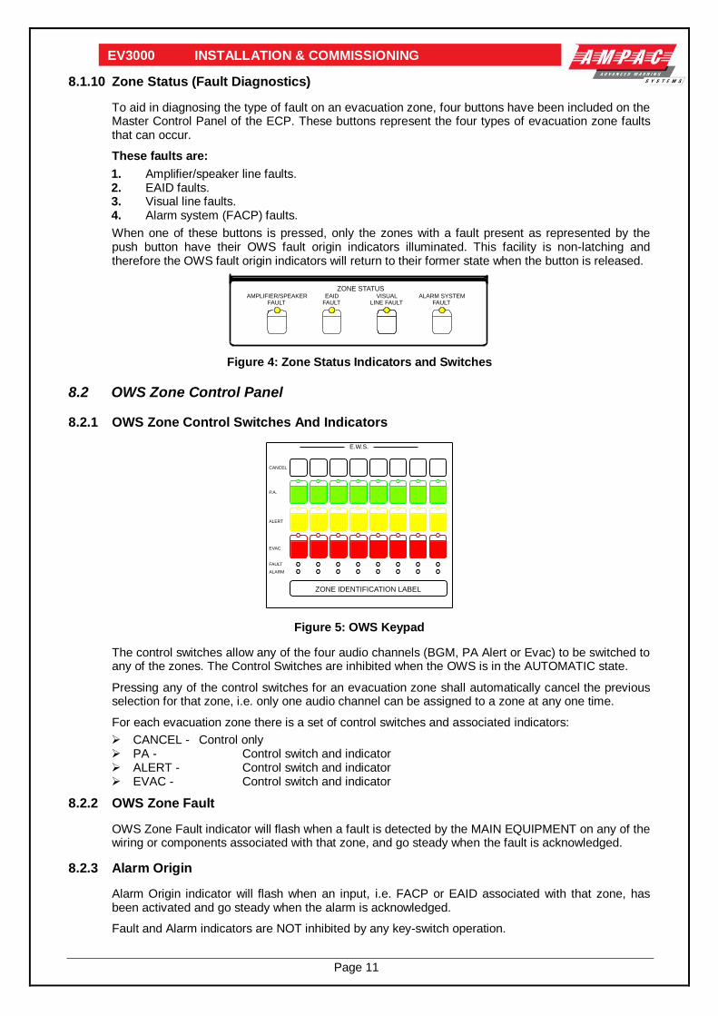
8.1.10 Zone Status (Fault Diagnostics)
To aid in diagnosing the type of fault on an evacuation zone, four buttons have been included on the Master Control Panel of the ECP. These buttons represent the four types of evacuation zone faults that can occur.
These faults are:
1. Amplifier/speaker line faults. 2. EAID faults. 3. Visual line faults. 4. Alarm system (FACP) faults.
When one of these buttons is pressed, only the zones with a fault present as represented by the push button have their OWS fault origin indicators illuminated. This facility is non-latching and therefore the OWS fault origin indicators will return to their former state when the button is released.
ZONE STATUSAMPLIFIER/SPEAKER
FAULTEAID
FAULTVISUAL
LINE FAULTALARM SYSTEM
FAULT
Figure 4: Zone Status Indicators and Switches
8.2 OWS Zone Control Panel
8.2.1 OWS Zone Control Switches And Indicators
E.W.S.
CANCEL
P.A.
ALERT
EVAC
FAULT
ALARM
ZONE IDENTIFICATION LABEL
Figure 5: OWS Keypad
The control switches allow any of the four audio channels (BGM, PA Alert or Evac) to be switched to any of the zones. The Control Switches are inhibited when the OWS is in the AUTOMATIC state.
Pressing any of the control switches for an evacuation zone shall automatically cancel the previous selection for that zone, i.e. only one audio channel can be assigned to a zone at any one time.
For each evacuation zone there is a set of control switches and associated indicators:
CANCEL - Control only PA - Control switch and indicator ALERT - Control switch and indicator EVAC - Control switch and indicator
8.2.2 OWS Zone Fault
OWS Zone Fault indicator will flash when a fault is detected by the MAIN EQUIPMENT on any of the wiring or components associated with that zone, and go steady when the fault is acknowledged.
8.2.3 Alarm Origin
Alarm Origin indicator will flash when an input, i.e. FACP or EAID associated with that zone, has been activated and go steady when the alarm is acknowledged.
Fault and Alarm indicators are NOT inhibited by any key-switch operation.

Page 12
EV3000 INSTALLATION & COMMISSIONING
8.2.4 Zone Labelling
Refer to Appendix A.
8.3 OIS Control Panel
E.I.S.
W.I.P.SELECT
ZONECLEARED
FAULT
W.I.P.SELECT
FAULT
ZONECLEARED
ZONE IDENTIFICATION LABEL
ZONE IDENTIFICATION LABEL
Figure 6: OIS Keypad
8.3.1 WIP Select Switch
(One switch per WIP) - when pressed for the first time will initiate a call to the WIP, or answer a call from a WIP. Pressing the switch a second time will terminate the call to the WIP regardless of who initiated the call.
8.3.2 WIP Select Indicator (Red)
(One indicator per WIP) - will flash when the ECP is calling the WIP and goes steady when the call is answered at the WIP. When the call is terminated, the indicator switches off. The indicator also flashes when the ECP is being called from a WIP and goes steady when the call is answered at the ECP.
8.3.3 WIP Call Buzzer
Sounds when the ECP is being called from the WIP. Buzzer switches off when the handset is picked up or the call is terminated.
8.3.4 Zone Cleared Switch
(One switch per evacuation zone) - when pressed for the first time will cause the Green ZONE CLEARED indicator to illuminate. Pressing the switch a second time will switch off the indicator. To function the MECP handset must be lifted first.
8.3.5 WIP Fault Indicator (Amber)
(One indicator per WIP) - indicator flashes when a fault associated with the WIP has been detected. Indicator goes steady upon acknowledgment.
8.4 OIS System Operation
8.4.1 WIP Calling ECP
The following is the procedure when initiating a call from a WIP to the ECP:
1. Remove the handset from the cradle at the WIP. This will cause the appropriate WIP select indicator to flash at all ECP’s and the WIP call buzzer to sound at all ECP’s.
2. A confidence tone can be heard at the WIP. 3. The ECP which responds to the call is referred to as the controlling ECP. The call is answered
at the ECP by removing the handset from the cradle and pressing the WIP select switch which corresponds to that WIP. A full duplex connection between the two parties is then established.

Page 13
EV3000 INSTALLATION & COMMISSIONING
8.4.2 Conference Call
If a second WIP initiates a call, the select indicator for that WIP will flash and if the WIP select switch corresponding to the second WIP is pressed, the select indicator for that WIP will go steady, and a conference call between the three parties is set up. Up to 5 WIP’s can be supported in this fashion. If a sixth WIP calls the ECP, the select switch of the sixth WIP is pressed, nothing will happen, i.e. the select indicator will remain flashing. The only way that the sixth WIP can be answered is if one of the 5 WIP’s involved in the conference call is cancelled the sixth WIP can then take its place.
8.4.3 Completing the Call by the WIP
If the WIP handset is placed back onto its cradle after the call is connected. The handset at the controlling ECP will go silent and the WIP select indicator will switch off, completing the call.
8.4.4 Completing the Call by the ECP
The call can be completed at the ECP in two ways. By replacing the handset on the cradle, OR by pressing the WIP select switch. In either case the WIP will return to the confidence tone. To be able to call or be calls again the WIP handset should be returned to its cradle.
8.4.5 ECP Calling WIP
The following is the procedure when initiating a call from the ECP to a WIP:
1. The confidence tone can be heard in the handset at the controlling ECP. 2. The WIP select switch corresponding to the WIP to be called is pressed, which causes the
WIP select indicator at the ECP’s to flash, and the buzzer to sound at the WIP. Up to 5 WIP’s can be called using this procedure.
3. Once the handset is picked up at the WIP the connection is established and the WIP select indicator becomes steady.
4. When the ECP is calling more than one WIP, the status of the calls, i.e. WIP answering is reflected in the WIP select indicators.
8.4.6 ECP To All WIPS (ALL CALL)
The following is the procedure when initiating an All CALL from the ECP to all WIP’s:
1. The confidence tone can be heard in the handset at the controlling ECP. 2. The All Call button is pressed; this causes all WIP select indicators at the ECP to flash. 3. The WIP’s, buzzers sound, with a 3 second or longer ON time and 3 second OFF time. This
allows the warden at the WIP to distinguish between a direct call to his WIP and an All Call type call.
4. When any of the WIP handsets are taken off the cradle, a connection is made and the WIP select indicator at the ECP goes steady. Similarly as more WIP handsets are taken off the cradle, their respective select indicators at the ECP go steady.
8.4.7 Completing The All Call
Replacing the ECP handset on its cradle i.e.: hanging up, will cancel the ALL CALL operation. Each WIP will be returned to the confidence tone.
8.4.8 OIS Controlling ECP
With the OWS in auto any ECP can be in control of the OIS by simply lifting the WIP handset at that ECP from its cradle. However, when an OWS is switched to the manual position it then has control of the OIS.
Again the MECP can override an SECP to take control of the OIS.
8.4.9 Zone Labelling - Refer to Appendix A

Page 14
EV3000 INSTALLATION & COMMISSIONING
8.4.10 Remote Paging Console
The Remote Paging Console (RPC) has been designed to provide PA. facilities at locations which may be remote from the E.C.P.
The RPC consists of a sloping front console with an alphanumeric keypad and a gooseneck type microphone. A 3 digit seven segment display is used to display the selected subzone(s) and there are 3 LED indicators for power, system busy and a press to talk indicator which verifies the operation of the push to talk (PTT) switch.
OPERATING INSTRUCTIONS
When the system is powering up the LED display will read In1. After the system powers up the LED display will be blank.
If the system busy LED is on, or the system is powering up, the RPC cannot be used. The system busy LED will be or if any other RPC is using the system or if the OWS system is activated at either the MECP or an SECP.
Note 1. When paging is in progress, fault monitoring on the amplifiers is inhibited.
Note 2. If the OWS overrides the RPC's, the RPC's are disconnected and the system busy LED's are turned on and the buzzer sounds for 3 seconds.
ZONE SELECTION
The RPC can be configured to access OWS zones as follows:
1. Subzones these may be selected zones or parts of zones of the OWS. 2. Groups these may be groups of subzones. 3. All Call this is used to select all subzones configured to a particular RPC.
SUBZONE SELECTION
To select a subzone, key in the required No. and press 'ENTER/CLEAR' e.g. to select subzone 4, press 4 followed by 'ENTER/CLEAR'.
The LED display will show 4 which will flash until the RPC has control of the OWS.
Once the RPC is connected press the 'PUSH TO TALK' button and speak into the microphone (NOTE a pre-announcement chime sounds when the PTT is pressed). To terminate the selection release the 'PUSH TO TALK' button and press 'ENTER/CLEAR'. Once the PTT is released if no other key is pressed, the RPC will automatically disconnect after 10 seconds.
To cancel an incorrect entry press 'ENTER/CLEAR' twice.
GROUP CALL
To select a group of subzones, press the 'GROUP' key followed by the group number key (e.g. 4) followed by 'ENTER/CLEAR'.
e.g. to select group 5 press 'GROUP' key followed by 5 followed by 'ENTER/CLEAR'. The LED display will show A5 which will flash until the RPC has control of the OWS.
ALL CALL
To select the all call facility press 'ALL CALL' followed by 'ENTER/CLEAR'. The display will show ALL which will flash until the RPC has control of the OWS.
WIRING CONNECTIONS
All wiring to RPC's is via pre wired connectors and modules are addressed / programmed in the factory.

Page 15
EV3000 INSTALLATION & COMMISSIONING
8.5 Main Equipment Description
The MAIN EQUIPMENT consists of the Common Control boards, Main CPU, OIS control cards, Amplifiers, Power Supply and Termination boards.
8.5.1 Common Board Frame
The common board frame is the top frame in the ECP and houses the following boards/modules.
Main Signal/Speech Generator Board (302 491B) Standby Signal/Speech Generator Board (302 491B if installed) Main Microphone/BGM Mixer Board (302 484) Standby Microphone/BGM Mixer Board (302 484 if installed. 2 x 251-0014 guide rails required) FACP Input CPU Board (302 620 if installed)
302-
491B
/ 15
4-00
76 S
PE
EC
H/T
ON
E G
EN
ER
AT
OR
(M
AIN
)
302-
491B
/ 15
4-00
76 S
PE
EC
H/T
ON
E G
EN
ER
AT
OR
(S
TAN
DB
Y)
30
2-4
84
MIC
/BG
M M
IXE
R (
MA
IN)
30
2-4
84
MIC
/BG
M M
IXE
R (
STA
ND
BY
)
30
2-6
20
SE
CO
ND
AR
Y C
PU
- F
IB I
NP
UT
Figure 7: Common Board Frame

Page 16
EV3000 INSTALLATION & COMMISSIONING
8.5.2 Signal/Speech Generator
The 302-491B is designed to produce the alert and evacuation tones and speech messages required for an evacuation system to Australian Standards AS1670.4 or NZS4512. Tones are digitally produced by microcontrollers for high stability and accuracy. Speech messages, which may be installed on either or both tones are microprocessor controlled but stored using the Information Storage Devices (ISD) Direct Analogue Storage Technology (DAST). Outputs from the card are low impedance to allow the card to drive 100 AMPAC EV3000 amplifiers (i.e. 40W and 120/240W).
8.5.3 Signal Generator Settings
SW 1 settings
Switch Off On
1-1 Evacuation message off Evacuation message on
1-2 Standard = AS1670.4 Standard = NZS4512
SW 2 settings
Switch Off On
1-1 Alert message off Alert message on
1-2 Standard = AS1670.4 Standard = NZS4512
SETTINGEVAC
SETTING
ALERT
MESSAGE
ALERT
MESSAGE
EVAC
POWER
SYNC 302 4910B TONE/SPEECH GENERATOR
EV
AC
AL
ER
T
NE
5534
5534
NE
LK1+
Q3
D1
+
Q6
+
+
+
+
+
SW1
68
HC
705
J2
IC1
IC3
SP
EE
CH VR4
TO
NE
VR3
TO
NE VR1
LED1
LED2
RL1
TX2
TX1
CN1
c a
IC2
LM7815
IC7
LM7805
IC8
+
Q4
Q5
SP
EE
CH
VR2
X1
IC5
68
HC
705
J2
IC4
SW2
+
IC6
++
+
+
EVAC SIGNAL / SPEECH LEVEL
ALERT SIGNAL / SPEECH LEVELS
ON
1 2
32
30
28
26
24
22
20
18
16
14
12
10
8
6
4
2
ON
1 2
Figure 8: 302-491B / 154-0076 Signal / Speech Generator
8.5.4 Standby / Speech Generator
This board is the STANDBY to the main signal speech generator board. Should the main board fail, the STANDBY board is automatically switched into circuit and the TONE fault indicator on the front panel is illuminated.

Page 17
EV3000 INSTALLATION & COMMISSIONING
8.5.5 Microphone / BGM Mixer Board
The microphone preamplifier board accepts inputs from the Panel MIC via a microphone preamp (302-475), Remote Paging Console and two BGM Inputs. The microphone inputs operate with a compression circuit to compensate for varying input levels. Level adjustments for both the main and remote microphones are provided to allow the user to set the system up for the specific requirements of the installation. The BGM inputs are provided with level controls and will be muted to all zones when:
OWS is operating from batteries Alarm signal is received in automatic or manual mode In manual mode and the zone control switches on the ECP are selected
Note: The background music is restored ONLY following a MASTER RESET operation.
RV4
RV5
RV2
RV3
TX8
TX4
TX6
IC2
IC3
TX5
TX7
TX2
IC7
C23
LED1
IC8
LK1
LED2
POWER
MICROPHONE MIXER 302-484C
+
+
ac
+
+
+
+
+
+
+
+
+ +
+321
+
OWS PA MIC
PAGING MIC
BGM 1
BGM 2
RFC2
32
30
28
26
24
22
20
18
16
14
12
10
8
6
4
2
Figure 9: 302-4840 Microphone / BGM Mixer
8.5.6 Standby Microphone / BGM Mixer Board
This board provides a complete duplicate of the main Microphone/BGM board and is automatically switched in when the system detects a failure in the main board. The Microphone fault indicator is also illuminated.
If level adjustments are required first remove the main Microphone/BGM Mixer.
8.5.7 FACP Input CPU Board
This board interfaces all the hard wired FACP inputs into the EV3000 Main CPU. When the EV3000 is installed with an AB3000 this board is not installed. The secondary CPU has an address setting which is factory set and should not be field adjusted.
8.5.8 Main CPU
The Main CPU is responsible for the total control of the OWS and OIS, the communication with other ECP’s, remote paging consoles, FireFinder and houses the program module.
The Main CPU has an Address setting that is factory set by way of a dipswitch. It also has another dipswitch which controls the time from alert to evacuation modes whilst in automatic. This time can be adjusted on site if required.
8.5.8.1 Program Eprom's
The EPROM's are located on the Main CPU and are responsible for the zoning of the FACP and EAID inputs and are programmed for each building.
The type of evacuation sequence and the outputs for the visuals are also controlled by the program EPROM's.

Page 18
EV3000 INSTALLATION & COMMISSIONING
8.5.9 Amplifier Rack Frame
Each Amplifier Rack Frame houses eight (8) 40 Watt zone amplifiers or four (4) 120 Watt amplifiers. Each frame has a motherboard (302-4760) which provides all necessary connections for the amplifiers as well as providing the address information required by the amplifiers to allow any zoning requirements. A complete list of all amplifier addresses can be found in Appendix B. Zone numbering is from the bottom frame left hand side upwards.
BGM Linking Options
Each zone amplifier can be connected by way of links to broadcast one of two BGM inputs. The links for this facility are found on the rear of the 302-4760 PCB. Refer to the Table and Figure below
Selection Un-even LK No’s 1-13 Even Link No’s 2-14
No Music Not Fitted Not Fitted
Music 1 1-2 1-2
Music 2 2-3 2-3
D3D5D6D7
CN4
ac
CN14CN17
CN9CN10CN11CN12
CN15CN16
CN13
LK7LK8 LK6 LK5 LK1LK2LK4 LK3
LK11LK12LK10 LK9LK13LK14
CN1
ac
CN2
ac
CN3
ac
CN5
ac
CN6
ac
CN7
ac
CN8
ac
LK16
1
2
3
LK15
D4
D1D
2
A
B
5 4 3 2 1
AMPLIFIERADDRESS
KEY
AUX
MUSIC
NE
GA
TIV
E
PO
SIT
IVE
PO
SIT
IVE
NE
GA
TIV
E
302-476 B
FAULT
OUTPUT1-4
FAULTOUTPUT
5-8
AUXINPUTS5-8
AUXINPUTS
1-4
1
2
3
PO
SIT
IVE
27
VD
C R
AIL
NE
GA
TIV
E 2
7V
DC
RA
IL
PO
SIT
IVE
27
VD
C R
AIL
NE
GA
TIV
E 2
7V
DC
RA
IL
AUX
MUSIC
AUX
MUSIC
AUX
MUSIC
AUX
MUSIC
AUX
MUSIC
AUX
MUSIC
A
B
5 4 3 2 1
AMPLIFIERADDRESS
KEY
A
B
5 4 3 2 1
AMPLIFIERADDRESS
KEY
A
B
5 4 3 2 1
AMPLIFIERADDRESS
KEY
A
B
5 4 3 2 1
AMPLIFIERADDRESS
KEY
A
B
5 4 3 2 1
AMPLIFIERADDRESS
KEY
A
B
5 4 3 2 1
AMPLIFIERADDRESS
KEY
A
B
5 4 3 2 1
AMPLIFIERADDRESS
KEY
1
2
3
1
2
3
1
2
3
1
2
3
1
2
3
1
2
3
1
2
3
1
2
3
1
2
3
1
2
3
1
2
3
1
2
3
1
2
3
1
2
3AUX
MUSIC
THIS SECTIONS ADDRESS KEY& MUSIC LINKS ENLARGEDFOR EXPLANATION PURPOSES
Figure 10: Amplifier Mother Board
8.5.10 40 Watt Amplifier
The 154-0075 (40W) monitored amplifier provides a 100V line output, all necessary circuitry to interface to the OWS and the attenuation for the Alert signal as required in AS2220. Minimum line impedance is 250Ω.
Each amplifier is provided with a level adjustment allowing adjustment of output level to each OWS zone.
N1236 4A
BRD EV3FWA3
POWER
FAULT
VOL ADJ
O/LOAD TX2
RV2RV5 RV3
TX1 LINE 100VLINE MATCHING
OPTO1
FS1
RV
1
32
30
28
26
24
22
20
18
16
14
12
10
8
6
4
2
c a
CN1
TB1U8
U3
U12
U9
U10
U6
U11
U2
U1
U5
U7
C4
Q3
Q7
Q9
RV4
Q5
R8
O/LOAD - FACTORY SET ONLY - O/P LEVEL
Figure 11: 40 Watt Amplifier with Heatsink / Cover & Transformer Removed

Page 19
EV3000 INSTALLATION & COMMISSIONING
8.5.11 120 Watt Amplifier
The 154-0077 (120W) amplifier option requires two amplifier positions and a minimum line impedance of 83Ω.
As in the case of the 40 Watt amplifier the output level can be adjusted by way of RV2 on the front of the 302 5690 card. RV1 And 2 on both boards are factory set and should not be adjusted.
TO API 578A BACKTO API 578A FRONT
ADJ.
ADJ.OVERLOAD
I0V
I-VE
HIGH VOLTAGEDANGERHIGH VOLTAGEDANGER
120 WATT AMPLIFIERAPI 569 D
O/LOAD
O/P LEVEL
IC4
IC5
IC2
IC11
TP3
+
+
+Q7Q9
Q6
Q5Q4 Q3 Q2
RV3
LED3
L2
L1
+
+
+
+
+
+
+
+
+
Q18 Q16
Q15 Q1
4
Q1
2
Q11
GAIN
RV
1
++
++
IC9
IC6 IC1
+
+
+
Q20
CN1
c a
A6
TP1
LED1
T1CN2
RV2
CN4
++
Q1 IC3
IC8
CN3
+C21+
LED2
Q1
3
I+VE
TP2
2A
F2
2A
F1
32
30
28
26
24
22
20
18
16
14
12
10
8
6
4
2
PWR
RV1, 2 FACTORY SET
Figure 12: 120 Watt Amplifier
WARNING HIGH VOLTAGE
10 AMP
API-570-DDC-DC CONVERTER120 WATT AMPLIFIER
24
+
+
T1
189
16
IC6
+
LED1
IC7
F1
IC1
ac
CN2
R10
+
IC2
IC8
Q10
LED3
LED2
Q1
Q2
+
++
++
++
++
++
++
++
++
+
+
+
RV2
RV1
IC5
+
T2
STUD2
STUD1
32
30
28
26
24
22
20
18
16
14
12
10
8
6
4
2
POWER
P/S SHUTDOWN
FAULT
RV1, 2FACTORY SET ON;Y
Figure 13: 120 Watt Amplifier DC to DC Converter
OVERLOAD LED RED
DC SUPPLY FUSE
10 AMPPOWER OUTPUT HEATSINK302-569
302-570
TOP SHIELD PLATE
FAULT LED RED
POWER ON
GREEN SHUT DOWNYELLOW
WHENEVER REMOVING OR
INSTALLING BOARDS-TURN OFF POWER-
OTHERWISEDAMAGE MAY OCCURE
WARNING
INDICATORS
Figure 14: 120Watt Complete Amplifier Assembly

Page 20
EV3000 INSTALLATION & COMMISSIONING
8.5.12 Warden Intercom Control Frame
The Warden Intercom Control Frame houses the following modules:
1. OIS Control CPU 2. OIS Selector Board (up to four boards) 3. EAID line card.
30
2-6
20
0 S
EC
ON
DA
RY
CP
U
30
2-6
15
1 E
IS L
INE
CA
RD
LIN
ES
1-4
30
2-6
15
1 E
IS L
INE
CA
RD
LIN
ES
5-8
30
2-6
15
1 E
IS L
INE
CA
RD
LIN
ES
9-1
2
30
2-6
15
1 E
IS L
INE
CA
RD
LIN
ES
13
-16
302-
6160
EA
ID IN
TE
RF
AC
E C
AR
D -
EA
ID 1
-16
Figure 15: OIS Control Frame
8.5.13 OIS Control CPU
This board provides the interface between the OIS selector board and the main CPU. The secondary CPU has an address setting which is factory set and should not be field adjusted.
Each CPU services four OIS selector boards, i.e. 16 WIP Extensions.
8.5.14 OIS Selector Board
The OIS selector board, 302 6150, provides the control, audio switching and ring signal to the WIP extension and services 4 WIP extensions.
8.5.15 EAID Line Card
The EAID line board 302 6160 provides the interfacing required for up to 16 EAID’s and is only fitted when required.
8.5.16 Fan Module
The Fan Module is provided to draw air through the cabinet to maintain an acceptable working temperature for all the equipment and is controlled by detecting any temperature increase in the power supply or by receiving a signal or input from the OWS.

Page 21
EV3000 INSTALLATION & COMMISSIONING
8.5.17 Power Supply
The Power Supply is supplied in two possible formats these are:
1. G0012 Modular Power Supply.
The G0012 Power Supply is constructed in two sections. These are a rectifier chassis mounted on the backpan and a regulator chassis mounted in the rack frame.
The rectifier chassis provides an unregulated DC which is then regulated by the regulator chassis to provide 27V DC to run the system and charge the batteries. The chassis also houses the 8V regulator required to provide the 8V DC requirement of the system.
The regulator chassis is modular in construction provides for up to four 27VDC modules, each able to deliver 8 A. Each module is adjusted in the factory and no attempt should be made to alter these adjustments.
2. G0018 Power Supply.
The G0018 Power supply is used only on smaller systems and SECP's and is mounted on a chassis on the backpan. It contains all componentry required to supply 27V to charge the batteries etc and also provide 8V for the microprocessor circuitry. As in the case of the G0012 all voltages are factory set and no attempt should be made to alter these settings.
3. Power Supply Supervisory Board
This board monitors the power supply/s, the battery isolated function, power supply temperature/s and initiates fan forced cooling as required.
ISOL
O N
ROLYTE
RED BLACK
RO
7
RO2
RO
3
RO
1
RO
10
RO
5
RO4
RO
6
RO
8
RO11
RO9
3
2
1LK2
3
2
1 LK1
D13
D11
R2
9
R30
R1
4
D14
D12
++
C9
R46
R3
1
R3
2
+
C7
+
C6
D10
D9D8
R15
R19
+
C3
+
C2
Q3
IC2
IC1IC4
D7
LED8FANS
LED7BATT
LED6ELECT-
LED5
LOW V
LED4
HIGH V
LED3
POWER
LED2
MAINS2
LED1
MAINS1
IC3
F1
1 AMP
N/C
C
N/O
SW1
FAN TEST
BUZZER
32
30
28
26
24
22
20
18
16
14
12
10
8
6
4
2
c aCN1
R33
R26
R27
R9
R2
R12
R13
R7
R11
+
C4
R8
R3
R4
R1
R5
R34
R35
C1
0D5
D4
D2
D3
R5
5
D20
R6
R4
3
R44
R5
3
C8
D15R36
R37R38
R39R40
D1D16
D17
D18
D19
ZD
1
R5
6
R4
1
R4
2
bc
e
Q2
R4
7
R4
5
R5
1
R5
0
R1
8
R2
1
R2
2
R4
8
R52
bc
e
Q5
R4
9
RV1
HIGH V
RV2
LOW V
RV
3
C1
R2
3
R2
4
bc
e
Q4
+
C11
C5
R2
8
R25
1
2
3
LK3
D2
1
D6
PUSH AND HOLD TO TESTCOOLING FAN OPERATION
SINGLE P/S OPERATIONINSERT LK1 & REMOVE LK2
DUAL P/S OPERATIONINSERT LK1 & LK2
INSERT LK1 IF ELECROLYTETESTING OPTION IS UTILISED
RV1 & RV2 ARE FACTORYSET AND SHOULD NOTBE ADJUSTED
RV3 - WITH THE BATTERYFUSE REMOVED ADJUSTANTI - CLOCKWISE UNTIL INTERMITTENT BUZZEROPERATION CEASES.
Figure 16: Power Supply Supervisory Board Layout
8.5.18 Fault Relay
The EV3000 has a fault relay which is normally operated. Should a fault occur in the EV3000 the
relay releases and the Warning System output of the FireFinder recognises and responds to the fault.
1234CN1
CON1879 4PIN PANDUIT
4
TB1D
+VE
3
TB1C
N/C
2
TB1B
COM
1
TB1A
N/O 4TB2D N/O
3
TB2C COM
2TB2B
N/C
1
TB2A -VE
D11N4004
4 RL1A
MR6213
RL1B
MR62
RL1C
MR62
R1*
2K2
D2*
RED
*LED INDICATOROPTIONAL
302-763
To CN18 of Master ControlPanel 302-479b of EV3000
10K
TB5 WARN SYSFire Finder 302-673
+ -
No
te:
On
ly u
sed in a
com
bin
ation
EV
30
00
/FireF
inder
Panel
N
Figure 17: EV3000 Fault Relay Wiring to the FireFinder

Page 22
EV3000 INSTALLATION & COMMISSIONING
9 Installation
9.1 Unpacking And Inspection
Carefully check packing prior to unpacking goods for any external transit damage. Unpack the goods and check the goods both externally and internally for any loose or damaged components or any problem which may affect the appearance, installation or operation of the goods.
Ensure all wiring harnesses are secure, all plugs are correctly fitted into their sockets, each circuit board is secure, and that all fixings and earth studs are tight.
If a plug-in type circuit board or ribbon connector becomes dislodged in transit, replace it in its socket and ensure that it is correctly mated.
If any damage has occurred you are to contact Ampac in writing within 14 days of receiving the goods in accordance with the Ampac Terms of Sale.
If the goods are of a nature which are accompanied by an Operators Manual you are requested to complete the Damage Report Form and return it to Ampac (Head Office) within 14 days of receiving the goods, in lieu of the written notification.
9.2 Anti-Static Precautions
To prevent damage to panel components please ensure prior to touching or handling any of the wiring or printed circuit boards within the OWIS that you are correctly earthed. The recommended method for personnel earthing is to use an anti static wrist strap and a flexible lead. Fit the wrist strap to yourself and attach the flexible lead to the cabinet earth bolt located inside the top of the cabinet.
Printed circuit boards removed from OWIS should be immediately placed in the anti static bags provided in the installation and maintenance kit.
9.3 Working On The System
To prevent damage to panel components please ensure prior to unplugging any connector, connecting or disconnecting any wiring, removing or replacing any module or board, that both the Mains and Batteries have been isolated. Batteries can be isolated by removing the system fuse mounted on the backpan.
9.4 Cabinet Installation
The EV3000 Cabinet may be surface or recess mounted. All indicators and controls shall be not less than 750mm and not more than 1850mm from the floor level.
9.4.1 Surface Mount
For surface mount the EV3000 Cabinet is secured by four bolts or screws through pre-drilled 12mm holes on the rear of the cabinet.
9.4.2 Recess Mount
For a recess mounting EV3000 Cabinet allow a cut-out equal to the size of the Cabinet plus 10mm all round clearance. The standard surround is 50mm wide and is secured with screws from the inside of the cabinet. Seal all unused knockouts and cable entries to prevent water or moisture entering the cabinet.

Page 23
EV3000 INSTALLATION & COMMISSIONING
10 Connecting The EV3000
All the field terminations are accommodated on the back pan of the Main Equipment.
10.1 FACP Input Connections (Individual inputs)
The 302-4940 is the Field Connection board for the FACP Inputs. Each board connection terminates sixteen FACP inputs.
10.1.1 Connections
Field Connections Use
TB1 - 1, 2, 3, 4 FACP Input 1 to 4
TB2 - 5, 6, 7, 8 FACP Input 5 to 8
TB3 - 9, 10, 11, 12 FACP Input 9 to 12
TB4 - 13, 14, 15, 16 FACP Input 13 to 16
TB6 - 1, 2 COMMON
FACP to provide voltage free, normally open contacts.
Install 10K EOL across each input to COMMON at the FACP end.
Factory Connections Use
CN1 - RS485 Communication input cable to FACP Input CPU.
CN2 - RS485 Communication cable to CN1 of the next FACP input connection board if installed.
CN3, CN4 - 8V and 27V DC supply cables.
10.1.2 Fusing
Fuse Use Rating
F1 8V supply 750 ma
10.1.3 Address Setting
Each board is addressed via SW1. The first switch is unused, the remaining seven (i.e. 2 to 8) operate on a binary code. This is factory set and should not be field adjusted.
F.I.P. INPUT BOARD
INPUTCOMMON
INPUT INPUT INPUT INPUT
16 15 14 13 12 11 10 9 8 7 6 5 4 3 2 1
CN1
CN2IC41
IC40
IC39
SW1IC38
IC37
F1CN3
TB5
IC9
TB4
TB3
IC18IC27
TB2 TB1
IC36
IC42
+
+
+
ON
1
2
3
4
5
6
7
8
750mA
RS485 IN
RS485 OUT
POWERIN
CN4 POWER OUT
Figure 18: 302-4940 FACP Input Board

Page 24
EV3000 INSTALLATION & COMMISSIONING
10.2 Common FACP Input Connections
Some EV3000 systems are fitted with a Common FACP input. Connection for the FACP input is provided on an 302 5860 Line Isolation Board. The 302 4940 board is not fitted when a Common FACP input is used.
Connections
Field Connection
TB1 - Line FACP input
Factory Connection
TB1 - EAID MECP EAID
(Terminated in 10KΩ if unused)
Figure 19: Common FACP Board
10.3 SECP MIC, BGM And SECP OIS Handset Input Connections
The 302-4990 is the field connection board for the Remote Microphones, BGM and the SECP OIS Handset Audio inputs. Each board will terminate four balanced audio inputs.
Note: Audio cable must be screened twisted 2 pair.
10.3.1 Connections
Field Connections Use
TB1 - L1, E, L2 Balanced Input No 1
TB3 - L1, E, L2 Balanced input No 2
TB7 - L1, E, L2 Balanced Input No 3
TB8 - L1, E, L2 Balanced Input No 4
The balanced audio line terminates to L1 and L2. E is the screen.
Factory Connections Use
TB2 - 1, 2 Earth
TB6 - 1, 2 Balanced Line to Mixer Board
TB4 - 1, 2 Balanced Line to Mixer Board
TB5 - 1, 2 Balanced Line to Mixer Board
TB9 - 1, 2 Balanced Line to Mixer Board
EARTH
OUTPUT4L1 E L2L2EL1
OUTPUT3OUTPUT2L1 E L2L2EL1
OUTPUT1
302-4990TB9
T4
TB8TB7
T3
TB5TB4
T2
TB3
TB2
TB1
T1
TB6
Figure 20: 302 4990 Audio Connection Board
302 5860
EA
ID
EIA
D
LIN
E
LIN
E
MO
V4
MO
V3
MOV2
MO
V1
TB1
CN1
L2
L1

Page 25
EV3000 INSTALLATION & COMMISSIONING
10.4 100V Line Speaker Connections
The 302-4900 is the field connection board for the speaker connections. Each board will terminate eight 100V line speaker circuits and eight volume control overrides. Each speaker circuit generally represents one evacuation zone.
10.4.1 Connections
Field Connections Use
TB1 - 1, 2 Output Evac Zone 1
TB1 - 3, 4 Output Evac Zone 2
TB2 - 1, 2 Output Evac Zone 3
TB2 - 3, 4 Output Evac Zone 4
TB3 - 1, 2 Output Evac Zone 5
TB3 - 3, 4 Output Evac Zone 6
TB4 - 1, 2 Output Evac Zone 7
TB4 - 3, 4 Output Evac Zone 8
TB5 - 1, 2 Volume Control Override
Factory Connections Use
CN1 Outputs from amplifiers 1 and 2
CN2 Outputs from amplifiers 3 and 4
CN3 Outputs from amplifiers 5 and 6
CN4 Outputs from amplifiers 7 and 8
CN5 Individual zone volume control outputs
TB7 -1 0V
TB7 -2 Common volume control
TB7 -3 27V
10.4.2 Fusing
Fuse Use Rating
F1 Volume Control Override 1 Amp
RL1
CN4CN1 CN2
3A
G
1A
MP
F1
TB1 TB2 TB3 TB4 TB5TB6
CN5
TB7
Q1
CN3
N/O
C
N/C
///
VCO OUTPUTS
- +
302 4900B
O/P 1 O/P 2 O/P 3 O/P 4 O/P 7 O/P 8O/P 6O/P 5 VCOGND
0 V 27VCTL
Figure 21: 302-4900 100V Line Termination Board

Page 26
EV3000 INSTALLATION & COMMISSIONING
10.5 Visual Indicators Output Connections
The 302-623B / 302-623C or the BRDEV3VOB3-A / BRDEV3VOB3-B are the field connection boards for the visual indicators. Each board will terminate four (4) zones of visual indicators.
Each zone output can cater for up to:
40 pair LED strobes.
16 pair XENON strobes.
The EV3000 visuals operate with a two-core cable to a pair of visual indicators, i.e. Alert (Amber), Evac (Red). Visuals are connected in reverse polarity to each other (See Figure 26 and 27).
NOTE: Circuit to visual indicators are polarised refer to section 11.2 for more detail.
10.5.1 Connections
Field Connections Use
TB1 - 1, 2 Output Pair Zone 1
TB2 - 1, 2 Output Pair Zone 2
TB3 - 1, 2 Output Pair Zone 3
TB4 - 1, 2 Output Pair Zone 4
Factory Connections Use
TB5-1,2 +24V
TB5-1,2 0V
CN1 Control Cable to 302 4220 board.
CN2 Control Cable to next 302-623B/C board or BRDEV3VOB*-A/B
10.5.2 Fusing
302-623B / C
Fuse Use Rating
F1 - 4 +24V Output 1 - 4 3 amp 3AG
BRDEV3VOB* A /B
Fuse Use Rating
F1 - 4 +24V Output 1 -4 3 amp M0205
27V27V0V0V
O/P1 O/P2 O/P3 O/P4
VISUAL OUTPUT BOARD302 6230B /C
TO MAF
TB5
+
+
Q10
Q7
Q1
Q4
IC1
Q2
RL1
///
N/C
C
N/O
RL2
///
N/C
C
N/O
F1 3A
CN1
CN2
Q3
TB1 TB2 TB3 TB4
RL3
N/O
C
N/C
///
RL4
N/O
C
N/C
///
Q6
Q5 Q8
Q9 Q12
Q11
LIN
K
IC2
SIL3
F2 3A
F3 3A
F4 3A
TO NEXT 302-6230
Figure 22: 302-623B Visual Output Board (XENON STROBES) /
302-623C Visual Output Board (LED STROBES)

Page 27
EV3000 INSTALLATION & COMMISSIONING
29/07/09
27V27V0V0V
O/P1 O/P2 O/P3 O/P4
VISUAL OUTPUT BOARD
BRDEV3VOB3-+- - + - + - +
TB5
+
+
Q10
Q7
Q1
Q4
IC1
Q2
M3
///
N/C
C
N/O
RL1
///
N/C
C
N/O
RL2
F1F2F3F4
CN1
CN2
Q3
TB1 TB2 TB3 TB4
N/O
C
N/C
///
RL3
N/O
C
N/C
///
RL4
M6
Q5 Q8
Q9
Q1
2
Q11
IC2
SIL3
TO MAF
TO NEXT BRDEV3VOB3
Figure 23: BRDEV3VOB3-A Visual Output Board (LED STROBES) /
BRDEV3VOB3-B Visual Output Board (XENON STROBES)
Page 28
EV3000 INSTALLATION & COMMISSIONING
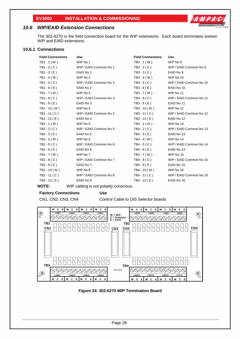
10.6 WIP/EAID Extension Connections
The 302-6270 is the field connection board for the WIP extensions. Each board terminates sixteen WIP and EAID extensions.
10.6.1 Connections
Field Connections Use Field Connections Use
TB1 - 1 ( W ) WIP No 1 TB3 - 1 ( W ) WIP No 9
TB1 - 2 ( C ) WIP / EAID Common No 1 TB3 - 2 ( C ) WIP / EAID Common No 9
TB1 - 3 ( E ) EAID No 1 TB3 - 3 ( E ) EAID No 9
TB1 - 4 ( W ) WIP No 2 TB3 - 4 ( W ) WIP No 10
TB1 - 5 ( C ) WIP / EAID Common No 2 TB3 - 5 ( C ) WIP / EAID Common No 10
TB1 - 6 ( E ) EAID No 2 TB3 - 6 ( E ) EAID No 10
TB1 - 7 ( W ) WIP No 3 TB3 - 7 ( W ) WIP No 11
TB1 - 8 ( C ) WIP / EAID Common No 3 TB3 - 8 ( C ) WIP / EAID Common No 11
TB1 - 9 ( E ) EAID No 3 TB3 - 9 ( E ) EAID No 11
TB1 - 10 ( W ) WIP No 4 TB3 - 10 ( W ) WIP No 12
TB1 - 11 ( C ) WIP / EAID Common No 4 TB3 - 11 ( C ) WIP / EAID Common No 12
TB1 - 12 ( E ) EAID No 4 TB3 - 12 ( E ) EAID No 12
TB2 - 1 ( W ) WIP No 5 TB4 - 1 ( W ) WIP No 13
TB2 - 2 ( C ) WIP / EAID Common No 5 TB4 - 2 ( C ) WIP / EAID Common No 13
TB2 - 3 ( E ) EAID No 5 TB4 - 3 ( E ) EAID No 13
TB2 - 4 ( W ) WIP No 6 TB4 - 4 ( W ) WIP No 14
TB2 - 5 ( C ) WIP / EAID Common No 6 TB4 - 5 ( C ) WIP / EAID Common No 14
TB2 - 6 ( E ) EAID No 6 TB4 - 6 ( E ) EAID No 14
TB2 - 7 ( W ) WIP No 7 TB4 - 7 ( W ) WIP No 15
TB2 - 8 ( C ) WIP / EAID Common No 7 TB4 - 8 ( C ) WIP / EAID Common No 15
TB2 - 9 ( E ) EAID No 7 TB4 - 9 ( E ) EAID No 15
TB2 - 10 ( W ) WIP No 8 TB4 - 10 ( W ) WIP No 16
TB2 - 11 ( C ) WIP / EAID Common No 8 TB4 - 11 ( C ) WIP / EAID Common No 16
TB2 - 12 ( E ) EAID No 8 TB4 - 12 ( E ) EAID No 16
NOTE: WIP cabling is not polarity conscious.
Factory Connections Use
CN1, CN2, CN3, CN4 Control Cable to OIS Selector boards
302 6270
LINE1
W C E
LINE2 LINE3 LINE4 LINE5 LINE6 LINE7 LINE8
LINE9 LINE10 LINE11 LINE12 LINE13 LINE14 LINE15 LINE16
W C E W C E W C E W C E W C E W C E W C E
W C E W C E W C E W C E W C E W C E W C E W C E
W = WIPC = CommonE = EAID
G3 G4
G2G1
TB2
TB3 TB4
TB1
CN1 CN2CN3 CN4
Figure 24: 302-6270 WIP Termination Board

Page 29
EV3000 INSTALLATION & COMMISSIONING
10.7 MECP To SECP Data Connections
The 302-4580 is the serial loop interface RS-485 connection board which provides communication via a redundant loop from the MECP to the SECP's.
10.7.1 Connections
Field Connections Use
CN3 - + COMMS Cable IN
CN3 - - COMMS Cable IN
CN3 - Shield SHIELD
CN4 - +COMMS Cable OUT
CN4 - - COMMS Cable OUT
CN4 - Shield SHIELD
NOTE: The polarity of the communication cable must be maintained.
Factory Connections Use
CN1 Internal COMMS Bus Out: CN13 ( MAF 302 – 4220 )
CN2 Internal COMMS Bus In: CN14 ( MAF 302 – 4220 )
10.8 CN5 + CN6 Power Supply to Board
10.8.1 Fusing
Fuse Use Rating
F1 8V DC Input 1 A (T) Pico
F2 Control Voltage 500 mA (T) Pico
F3 Control Voltage 500 mA (T) Pico
EARTH
900202882046 22130
302-4580
SHIELD
SH
IEL
D-
+S
HIE
LD
-+
COMMS OUT +
COMMS OUT -
COMMS IN +
COMMS IN -
SHIELD
F2
F3
D12D10
Q3U16
F1+8
CN2
CN1
U3
U5
U2
U1
U4
Q2
U10
U9
U12CN4
CN6 CN5 CN3U11
U7
U8
Q1
TX1
U14
U15
U13
+
Q4
Q5
+5
TOCN13
TOCN14
MAF
Figure 25: 302-4580 Serial Isolation Board
Note: Comms cable must be screened twisted 2 pair.

Page 30
EV3000 INSTALLATION & COMMISSIONING
10.9 Mains Connection
Mains supply shall be 240VAC (+6%, -10%) at 50HZ and installed in accordance with AS3000 and AS1670-1986.
Ensure Mains is isolated at the building distribution board prior to the connection of the Mains cable.
Terminate the 240VAC mains supply cable to the 240VAC switch block located on the back pan.
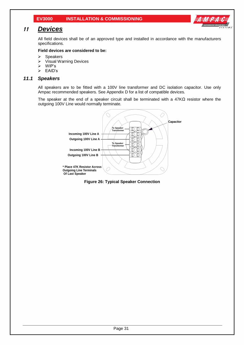
Page 31
EV3000 INSTALLATION & COMMISSIONING
11 Devices
All field devices shall be of an approved type and installed in accordance with the manufacturers specifications.
Field devices are considered to be:
Speakers Visual Warning Devices WIP’s EAID’s
11.1 Speakers
All speakers are to be fitted with a 100V line transformer and DC isolation capacitor. Use only Ampac recommended speakers. See Appendix D for a list of compatible devices.
The speaker at the end of a speaker circuit shall be terminated with a 47KΩ resistor where the outgoing 100V Line would normally terminate.
To SpeakerTransformer
To SpeakerTransformer
Incoming 100V Line A
Outgoing 100V Line A
Incoming 100V Line B
Outgoing 100V Line B
* Place 47K Resistor AcrossOutgoing Line Terminals Of Last Speaker
Capacitor
Figure 26: Typical Speaker Connection

Page 32
EV3000 INSTALLATION & COMMISSIONING
11.2 Visual Warning Devices
Visual warning devices must be capable of operating on 24V DC (nominal). See Appendix D for a list of approved types.
Each visual output from the EV3000 will operate a pair of indicators, i.e. an Alert and Evac indicator. Visual pairs are fitted in reverse polarity.
FROM 302-623B /BRDEV3VOB3-BVISUAL WARNINGDEVICE DRIVERBOARD (OWIS)
ALERT(AMBER)
EVAC(RED)
1
2
3
4OUT
Figure 27: Visual Indicator Connections (XENON STROBES) 208-0011
-VE
IN/OUT+VEIN +V
EOU
TLED-
ALERT(AMBER)
EVAC(RED)
N1236
OUT
-VE
IN/OUT+VEIN +V
EOU
TLED-
N1236GND GND
FROM 302-623C /BRDEV3VOB3-AVISUAL WARNINGDEVICE DRIVERBOARD (OWIS)
Figure 28: Visual Indicator Connections (LED STROBES) 208-0063

Page 33
EV3000 INSTALLATION & COMMISSIONING
11.3 Warden Intercommunication Point (WIP)
Each WIP is cabled individually from the main equipment.
The preferred method for cabling into the WIP is via the entry hole in the base of the WIP.
Terminate WIP cabling from the ECP into:
TB1-1 labelled “W”
TB1-2 labelled “C”.
TB1-3 labelled “E”.
If it is not possible to pass the cables through the rear of the case, the entry may be made by removing one or more of the “knockouts (Arrows)” as shown below. In no instance should cabling enter the case via the left top of the case, neither should cabling (or any other obstruction) foul the buzzer.
C2
C1
TB
1
L1
C5
+
D7
D6D5C9
C8
C6
C4
+
C3
Q4
Q3
Q2
Q1
R19
R18
R17
R16
R14
R13 R12
R11
R10R9
R8
R7R6
R5R4
R
R2
R
D4D3 D2D1
SW
R20
C7
C10
M1
PZ1
614
-B+B
AP
I
LEDLED
AK
W C E EA
ID
EA
ID
TO ECP
KEEP
OBSTRUCTIONS CLEAR OF BUZZER
CAUTION AM
PA
CW
AR
DE
N I
NT
ER
CO
M P
HO
NE
GD0070 WIP
C2
C1
TB
1
L1
C5
+
D7
D6D5C9
C8
C6
C4
+
C3
Q4
Q3
Q2
Q1
R19
R18
R17
R16
R14
R13 R12
R11
R10R9
R8
R7R6
R5R4
R
R2
R
D4D3 D2D1
SW
R20
C7
C10
M1
PZ1
614
-B+B
AP
I
LEDLED
AK
W C E EA
ID
EA
ID
TO ECP
KEEP
OBSTRUCTIONS CLEAR OF BUZZER
CAUTION AM
PA
CW
AR
DE
N I
NT
ER
CO
M P
HO
NE
GD0070 WIP
AM
PAC
ALTERNATIVECABLEENTRY POINTS
CORRECT METHODS INCORRECT METHOD
Figure 29: Wiring of WIP

Page 34
EV3000 INSTALLATION & COMMISSIONING
11.4 EAID
If EAID's are cabled to the main equipment they will be connected to the FACP input connection board.
EAID's are connected to the OWIS and not the Fire System. This means that the manual operation of an EAID will trigger the Occupant Warning System and NOT indicate on the Fire System or signal the Fire Services.
IF the EAID is in close proximity to a WIP, then wiring can be reduced by connecting the EAID to the WIP as shown below. Wiring in this manner requires that the following criterion is met.
Cabling from the WIP to the ECP must be by fire rated three-core cable. No spurs or T junctions, cables must be a single run come individual lines. An EAID interface card (302 616) must fitted to ECP.
CN
1
BRDEV3WIP2-
27/03/09
EAID
EAID
BUZ-
BUZ+
WC
E
KE
EP
CL
EA
R O
F B
UZ
ZE
R
CA
UT
ION
:
com
spk
mic
+
R2
C5
C4
C3
C2
C1
N1
23
6
ZD
3
ZD
2
ZD1
R1
02
R101
R28
R27
R2
6
R25
R2
4
R2
3
R22
R2
1
R20
R1
9
R18
R1
7
R1
6
R15
R14
R13
R12
R1
1
R10
R9
R8
R7
R6R
5
R4
R3
R1
Q6
Q5
Q4
Q3
Q2
Q1
L1
D1
2
D1
1
D10
D9
D8
D7
D6
D5
D2
D1
C14
C1
3
C12
C1
1
C1
0
C9
C8
C7
C6
+
BZ
1
PZ
1
SW
1
TB
1
C1
5
C16
C1
7
Q7
C1
8
D1
3
LK
1
R2
9
AP
I 6
27
LIN
E1
WC
EL
INE
2L
INE
3L
INE
4L
INE
5L
INE
6L
INE
7L
INE
8
LIN
E9
LIN
E1
0L
INE
11
LIN
E1
2L
INE
13
LIN
E1
4L
INE
15
LIN
E1
6
WC
EW
CE
WC
EW
CE
WC
EW
CE
WC
E
WC
EW
CE
WC
EW
CE
WC
EW
CE
WC
EW
CE
W =
WIP
C =
Co
mm
on
E =
EA
ID
G3
G4
G2
G1
TB
2
TB
3T
B4
TB
1 M1
TB12
M2
TB12
M3
TB12
M4
TB12
M5
TB12
M6
TB12
M7
TB12
M8
TB12
M9
TB12
M1
0TB12
M1
1
TB12
M1
2
TB12
M1
3
TB12
M1
4
TB12
M1
5
TB12
M1
6
TB12
M1
7
TB12
M1
8
TB12
M1
9
TB12
M2
0
TB12
M2
1
TB12
M2
2
TB12
M2
3
TB12
M2
4
TB12
M2
5 TB12
M2
6 TB12
M2
7 TB12
M2
8 TB12
M2
9 TB12
M3
0 TB12
M3
1 TB12
M3
2 TB12
M3
3 TB12
M3
4 TB12
M3
5 TB12
M3
6 TB12
M3
7 TB12
M3
8 TB12
M3
9 TB12
M4
0 TB12
M4
1 TB12
M4
2 TB12
M4
3 TB12
M4
4 TB12
M4
5 TB12
M4
6 TB12
M4
7 TB12
M4
8 TB12
CN
1C
N2
CN
3C
N4
EIS TERMINATION BOARD (API-627)
EA
ID
10
K
EAID (213-0062)
NOTE: FIT LK1
CN
1
BRDEV3WIP2-
27/03/09
EAID
EAID
BUZ-
BUZ+
WC
E
KE
EP
CL
EA
R O
F B
UZ
ZE
R
CA
UT
ION
:
com
spk
mic
+
R2
C5
C4
C3
C2
C1
N1
23
6
ZD
3
ZD
2
ZD1
R1
02
R101
R28
R27
R2
6
R25
R2
4
R2
3
R22
R2
1
R20
R1
9
R18
R1
7
R1
6
R15
R14
R13
R12
R1
1
R10
R9
R8
R7
R6R
5
R4
R3
R1
Q6
Q5
Q4
Q3
Q2
Q1
L1
D1
2
D1
1
D10
D9
D8
D7
D6
D5
D2
D1
C14
C1
3
C12
C1
1
C1
0
C9
C8
C7
C6
+
BZ
1
PZ
1
SW
1
TB
1
C1
5
C16
C1
7
Q7
C1
8
D1
3
LK
1
R2
9
WIP 3 WIRE (219-0015)
NOTE: FIT 10KACROSS EAID O/P IF NO EAIDFITTED
NOTE: FIT LK1
WIP 3 WIRE (219-0015)
Figure 30: EAID to WIP Wiring
If an EAID is to be fitted in this manner then the third line from the ECP is connected to TB1-3 which is labelled “E”. The EAID is then terminated to TB1-4 and TB1-5 and labelled “EAID” under the ideogram of a switch. For correct operation a 10K resistor must be fitted across the switch contacts of the EAID, or if multiple EAID's are to be installed on one circuit then the EOL resistor must be installed in the device at the end of the circuit.

Page 35
EV3000 INSTALLATION & COMMISSIONING
12 SECP And Remote Console Connections
2 C
OR
E 0
.75
mm
(N
OT
F.R
.)
1 P
AIR
0.7
5m
m T
WIS
TE
D S
CR
EE
NE
D A
UD
IO (
NO
T F
.R.)
1 P
AIR
0.7
5m
m T
WIS
TE
D S
CR
EE
NE
D D
AT
A/A
UD
IO *
CA
BL
E T
YP
E L
EG
EN
D
*
RA
DO
X S
ER
IES
FR
CO
MM
UN
ICA
TIO
N
M
US
T B
E S
ING
LE
PA
IR.
NO
TU
SE
D
NO
TU
SE
D
NO
TU
SE
D
LO
OP
AD
DR
ES
S 6
LO
OP
AD
DR
ES
S 5
LO
OP
AD
DR
ES
S 4
LO
OP
AD
DR
ES
S 1
LO
OP
AD
DR
ES
S 2
LO
OP
AD
DR
ES
S 3
NO
TE
S:
1.
MA
XIM
UM
NU
MB
ER
OF
LO
OP
MO
DU
LE
S I
S 5
02
. R
EM
OT
E P
AG
ING
CO
NS
OL
ES
CA
N E
ITH
ER
B
E P
OW
ER
ED
FR
OM
AN
EC
P O
R T
HE
IR O
WN
9
VD
C P
LU
GP
AC
K(O
PT
ION
AL
).3
. T
HIS
IS
A T
ER
MIN
AT
ION
DR
AW
ING
RE
FE
R
TO
DR
AW
ING
G0
01
0 S
HT
DB
E F
OR
GE
NE
RA
L
SY
ST
EM
LA
YO
UT
.4
. T
HIS
DR
AW
ING
IS
FO
R I
NF
OR
MA
TIO
N O
NL
Y
RE
FE
R T
O A
MP
AC
FO
R S
PE
CIF
IC
A
PP
LIC
AT
ION
S.
24
0V
AC
9 V
OL
TP
LU
G P
AC
K1
.7A
(OP
TIO
NA
L)
-VE
+V
E+
VE
-VE
+V
E
-VE
GN
D
GN
D
-VE
+V
E
+V
E
-VE
GN
D
GN
D
-VE
+V
E
+V
E
-VE
GN
D
RP
CA
UD
IOB
US
RP
CP
OW
ER
RS
48
5C
OM
MS
OU
T
OW
SA
UD
IOB
US
OIS
AU
DIO
BU
S
RS
48
5C
OM
MS
INMA
ST
ER
EM
ER
GE
NC
YC
ON
TR
OL P
AN
EL
SE
CO
ND
AR
Y E
ME
RG
EN
CY
CO
NT
RO
L P
AN
EL
RS
48
5C
OM
MS
IN
OIS
AU
DIO
BU
S
OW
SA
UD
IOB
US
RS
48
5C
OM
MS
OU
T
RP
CP
OW
ER
RP
CA
UD
IOB
US
GN
D
-VE
+V
E
+V
E
-VE
GN
D
GN
D
-VE
+V
E
+V
E
-VE
GN
D
GN
D
-VE
+V
E
-VE
+V
E+
VE
-VE
DA
TA
GA
TH
ER
ING
PA
NE
L
RS
48
5C
OM
MS
IN
OIS
AU
DIO
BU
S
OW
SA
UD
IOB
US
RS
48
5C
OM
MS
OU
T
RP
CP
OW
ER
RP
CA
UD
IOB
US
GN
D
-VE
+V
E
+V
E
-VE
GN
D
GN
D
-VE
+V
E
+V
E
-VE
GN
D
GN
D
-VE
+V
E
-VE
+V
E+
VE
-VE
RE
MO
TE
PA
GIN
G C
ON
SO
LE
14
13
12
11
10
9
87
65
43
2
15
1
RE
MO
TE
PA
GIN
G C
ON
SO
LE
14
13
12
11
10
9
87
65
43
2
15
1
RE
MO
TE
PA
GIN
G C
ON
SO
LE
14
13
12
11
10
9
87
65
43
2
15
1
CO
MM
S IN
+V
E
CO
MM
S IN
-VE
CO
MM
S IN
SH
IELD
CO
MM
S O
UT +
VE
CO
MM
S O
UT -V
E
CO
MM
S O
UT S
HIE
LD
AU
DIO
+V
E
AU
DIO
-VE
MIC
SH
IELD
PO
WE
R +
9VD
C
POW
ER -0
V
NO
TE
: E
AC
H +
VE
AN
D -
VE
PA
IR I
S T
WIS
TE
D T
OG
ET
HE
R
BLA
CK
2.5
mm
RE
D 2
.5m
m
GR
EE
N 1
mm
BLU
E 1
mm
OR
AN
GE
1m
m
TH
ES
E
PA
IRS
TW
IST
ED
RE
MO
TE
PA
GIN
G C
ON
SO
LE
9.
N/C
10
. C
OM
MS
OU
T G
ND
11
. C
OM
MS
OU
T -
VE
12
. C
OM
MS
OU
T +
VE
13
. C
OM
MS
IN
GN
D1
4.
CO
MM
S I
N -
VE
15
. C
OM
MS
IN
+V
E
1.
PO
WE
R -
VE
2.
MIC
GN
D3
. M
IC -
VE
4.
MIC
+V
E5
. N
/C6
. N
/C7
. N
/C8
. P
OW
ER
+V
E
14
13
12
11
10
9
87
65
43
2
15
1
Figure 31: SECP and Paging Console Setup

Page 36
EV3000 INSTALLATION & COMMISSIONING
13 Placing System Into Operation
Prior to system power up ensure that:
All field connections are completed and free of faults. Remove the foam transit packing in and around the connectors of boards 302-422 & 302-479 All modules are securely mounted. All boards are plugged in (including power amplifier modules). Auto Manual Isolate switch is in the Manual position. All EOL resistors are fitted. No alarm signals exist at FACP if connected to the EV3000. Complete checks as per EV3000 Commissioning Report.
13.1 System Power Up Sequence
The system is now ready for power up.
Turn the Mains power, switch ON.
Normal power up sequence shall:
Turn the indicators on the “Emergency control panel” ON momentarily for 2 to 4 seconds. Turn ON all the indicators on the OWS and OIS control panels, then switching them off again in
a running sequence. Turn ON the auto (LED) indicator. Activate the internal buzzer (the buzzer can be muted with Buzzer Mute during system power
up).
On completing the power up sequence the:
Comms fault/system fault/module fault indicators are OFF. OWS and OIS control indicators are OFF.
Note: The duration of the power up sequence is on average from two to five minutes.
System batteries can now be connected observing correct polarity.
The system is now ready for operation.

Page 37
EV3000 INSTALLATION & COMMISSIONING
13.2 Time Out Setting For Automatic Evacuation Sequence
The selection of the time can be achieved either before or after the power up sequence.
The time base is ten (10) seconds, i.e. the minimum time out possible is 10 seconds to a maximum of 10 minutes in 10 second increments. An eight position DIL switch located on the rear of the 302-4220 main CPU Board (refer Figure 27) is provided to select the required time out.
API-422-C
MEMORY
MODULE
EXPANSION
32
31
30
29
28
27
26
25
24
23
22
21
20
19
18
17
16
15
14
13
12
11
10
9
8
7
6
5
4
3
2
1
SW5 DONOTTOUCH
CN24
CN17CN16CN15CN14CN13
CN12
CN4
CN1
CN3
CN5
CN6
+
CN10
CN11
CN7
CN8
CN9
CN26
CN23
RESET
TIME OUTSELECTIONSWITCH
ON
1 2 3 4 5 6 7 8
ON
1 2 3 4 5 6 7 8
Figure 32: Switch settings
SETTING THE TIME OUT
The total time out is calculated by adding the count of the switches that are “ ON “ as shown below, PLUS one (1) and then multiplying this total by the base time. The base time is usually ten seconds unless stated otherwise.
ON
1 2 3 4 5 6 7 8
1 2 4 8 16 32
SWITCHES 7 & 8ARE NOT USED
ON
SWITCHNUMBERS
COUNT
Figure 33: Switch Settings
Example: Switches numbered 2 + 3 are ON, all others are OFF
The count for the Timeout is therefore = (2 + 4 + 1) x 10 = 70 seconds

Page 38
EV3000 INSTALLATION & COMMISSIONING
14 Faults
14.1 Fault Indicators
In normal operation the LED indicators illuminated are the "power on" and the "auto" LED.
There are five types of fault LEDS.
1. "Module Fault" LED.
A Module Fault indicates that a local module is either disconnected or faulty.
2. "System Fault" LED.
A System Fault indicates that a module or Main CPU has failed anywhere in the system.
3. "Communications Fault" LED.
A Communications Fault indicates that the one of the communication lines between ECP's/RPC's is faulty.
4. "Auxiliary Fault" LEDS.
The Auxiliary Fault LED's indicate that a non processor module is not functioning.
5. "Zone Fault" LEDS.
The Zone Fault LED’s allow detection of faults within OWS and OIS zones.
Note: The Fault Sounder will operate, sounding one second pulses every two seconds, if a fault condition exists on any circuit or its associated module.
Refer to Section 8.1.9 for more information.
14.2 Fault Diagnostics
To help with fault diagnosis the MECP will identify zone fault types.
To this end four zone fault diagnosis buttons are included on the Emergency Control Panel.
Refer to Section 8. for the operation of these switches.

Page 39
EV3000 INSTALLATION & COMMISSIONING
15 Trouble Shooting
Prior to conducting any trouble shooting checks it is desirable that the status of any abnormal condition is recorded.
Fault/Status Cause Solution
Mains On Indicator Is
Off
Mains At Dist Board Off. Mains Switch Off. Cn1 On M.C.P.
Cn6 On PSU Mother Brd Discon'd. Mains Fuse Blown.
Turn Power On. Turn Mains Switch On. Plug In Correctly.
Plug In Correctly. Replace Fuse.
System On Batteries.
Mains At Dist Board Off. Mains Power Failure.
Mains Switch Off. Mains Fuse Blown.
Turn Power On, Check For Main On Indicator When Power Is Returned.
Turn Mains Switch On, Replace Fuse.
Charger Fault
Mains Fail. High Volts:
Charger Output Volts Above 28.5 Volts. Voltage Normal At 28.5 Volts. Low Volts:
Charger Output Volts Below 24.5 Volts. Batteries Fault. Voltage Normal At 24.5 Volts.
Ref Mains On Ind And System On
Batteries. Fault Status. Replace Charger Module On Power
Supply. Replace Supervisory Card On P/S.
Replace Charger Module On Power Supply. Replace Batteries.
Replace Supervisory Card On P/S.
Battery Fault Indicator
On After 24 Hours.
Battery Disconnected OR Battery Isolate. Battery Voltage Below 24.5 Volts.
Low Electrolyte.
Connect Batteries. Replace Batteries.
Top Up Batteries.
Battery Isolate.
Main D.C. System Fuse.
Battery Cable Loose Or Disconnected.
Plug In Correctly Or Replace Fuse. Check Connections.
Signal Fault.
PCB Signal Gen Not Plugged In Correctly. DC Distribution Fuse Blown On Rear Of Common
Board Frame. Synthesiser Fault.
Signal Levels Too Low.
Plug PCB In.
Replace Fuse 1 Amp. Replace 302-4910 / 154-0076 Signal/Speech Generator.
Adjust Signal Levels.
Signal Fault Comes On
Intermittently
Code Set On Dip Switch On Signal Generator For
Message Length Incorrect Evac Or Alert Signal Levels Too Low
Set Dipswitch To Correct Code.
Readjust Signal Levels.
Comms Fault Section Of The RS 485 Loop Or Internal Comms Bus Faulty Or Disconnected From Module. (Cn13 And Cn14 Of Processor Brd)
Check Section And Termination Or Field
Wiring. Check Internal Comms Connections. Ensure All Modules Are Plugged In. Ensure Modules Installed In
Correct Order.
System Fault Module Or Cpu Within Entire System Faulty. Identify MECP Or SECP Displaying Module Or Cpu Fault. Ref Module Fault Or
Cpu Fault Instructions.
Module Fault. Module Containing
RS485 Comms Is Faulty. Local To That MECP Or SECP.
DC Fuse On Module Is Blown. DC Distribution Fuse Blown On Rear Or Common
Board Frame. Faulty Module. Faulty Cabling (CN15 & CN17).
Replace Fuse.
Replace Fuse. Replace Module.
Microphone Fault
302 4840 Brd Not Plugged In Correctly. Dc Distribution Fuse Blown On Rear Of Common
Board Frame. Faulty Pre-Amplifier Section.
Plug In Correctly. Replace Fuse 1amp.
302 4840 Faulty Replace Module.
OWS Zone Fault. Amplifier/Speak.
Speaker Cabling Faulty: Short Or Open Circuit Cable. No Eol Resistor.
No DC Isolation Capacitors Fitted, (Incorrect Speaker Type). Amplifier Faulty:
Blown Fuse On Amplifier. Faulty Amplifier. Amplifier Not Plugged In
Correctly.
Check As Per Clause 4.2 In EV3000 Commissioning Report.
Fit 47k Eol Resistor. Fit Capacitors Or Change Speakers
Replace Fuse 5amp. Replace Amplifier. Plug In Correctly.
OWS Zone Fault. Amp/Spkr Fault - All
Zones.
Mic Mixer 302 4840 Unplugged. Test Signal Generator On 302 4840 Faulty.
Amplifier Bus Cable Unplugged Or Faulty.
Plug 302 4840 Back In. Replace 302 4840.
Reconnect Or Replace

Page 40
EV3000 INSTALLATION & COMMISSIONING
OWS Zone Fault. EAID.
EAID Cabling Faulty.
Open Cable Between EAID and WIP. No EOL Resistor At EAID.
Check Cable And Connections.
Install 10k EOL.
OWS Zone Fault. Visual.
Visual Cabling Faulty. Open Or Short Circuit Cable To Visual Line Fuse On Visual Output Connection Board Down.
Check Cabling And Connections. Replace Fuse 1amp.
OWS Zone Fault. Alarm System.
Alarm System Cabling Faulty. Open Circuit Cable To Alarm System. No EOLResistor At Alarm System
Faulty FACP Input Connection Board.
Check Cable And Connections. Install 10k Resistor At Alarm System End
Of Cable. Replace Board.
OIS Zone Fault. WIP Cabling Faulty. Line Fuse On OIS Selector Board Blown 302-615.
Check Cable And Connections.
Replace Fuse Pico 1 Amp. Check As Per Clause 3.3 In EV3000 Commissions Report.
OWS Zone Fault. No Fault Indication In
Zone Status.
Faulty Common BGA On Panel.
Check 10k EOL Installed. Check BGA Ok. Check Wiring From Panel BGA To
302-4790 Master Keyswitch Panel.

Page 41
EV3000 INSTALLATION & COMMISSIONING
16 Appendix A: Zone Labelling
ECP ZONE LABELLING
Normally AMPAC panels are supplied with labelling installed as per the customers requirements. These are supplied in the format shown below for both the OWS and OIS.
Each zone identifier can contain up to four (4) lines of text each being nine (9) characters long.
REF
15.00 mm
RE
F
8.2
0 m
m
23.5
0 m
m
38.8
0 m
m
54.0
0 m
m
69.3
0 m
m
84.5
0 m
m
99.8
0 m
m
115.0
0 m
m
125.0
0 m
m
Material 0.5mm Card
ZONE 1 ZONE 2 ZONE 3 ZONE 4 ZONE 5 ZONE 6 ZONE 7 ZONE 8
Figure 34: EV3000 Label Requirements
(ACTUAL WINDOW USEABLE SIZE 120mm x 10mm)

Page 42
EV3000 INSTALLATION & COMMISSIONING
17 Appendix B: Compatible Devices
LIST OF COMPATIBLE DEVICES
SPEAKERS:
218-0008 100mm Speaker Recess Ceiling Mount
218-0026 100mm Speaker C/W Quick Fit Grill
218-0009 Speaker Recess Ceiling Mount
218-0003 100mm Grill
218-0021 200mm Grill
EAIDS:
213-0062 ACP-04 MCP SQUARE WHITE
VISUALWARNING DEVICES:
208-0011 24V STROBE LIGHT COMBINED RED/AMBER
208-0060 SONOS Led Strobe RED
208-0061 SONOS Led Strobe AMBER
208-0062 SONOS Led Strobe CLEAR LENS
208-0063 SONOS Led Strobe COMBINED RED/AMBER (Flush Mount)
208-0064 SONOS Led Strobe DEEP BASE
208-0065 SONOS Led Strobe COMBINED RED/AMBER IP65
208-0066 SONOS Led Strobe COMBINED RED/AMBER (Surface Mount)
WIPS:
219-0009 EV3000 EIS 3W WIP MASTER HANDSET
219-0013 EV3000 EIS 2W + 3W TS004 WIP MASTER HANDSET
219-0015 EV3000 EIS 2W + 3W TS004 SLAVE WIP HANDSET

Page 43
EV3000 INSTALLATION & COMMISSIONING
18 Appendix C: Amplifier Addressing
BINARY ADDRESS SETTING
ADDRESS DATA
DIL SWITCH: ON = 1 OFF = 0
ADDR DIL SWITCH 1234567
ADDR DIL SWITCH 1234567
ADDR DIL SWITCH 1234567
ADDR DIL SWITCH 1234567
1 1000000 33 1000010 65 1000001 97 1000011
2 0100000 34 0100010 66 0100001 98 0100011 3 1100000 35 1100010 67 1100001 99 1100011 4 0010000 36 0010010 68 0010001 100 0010011
5 1010000 37 1010010 69 1010001 101 1010011 6 0110000 38 0110010 70 0110001 102 0110011 7 1110000 39 1110010 71 1110001 103 1110011
8 0001000 40 0001010 72 0001001 104 0001011 9 1001000 41 1001010 73 1001001 105 1001011 10 0101000 42 0101010 74 0101001 106 0101011
11 1101000 43 1101010 75 1101001 107 1101011 12 0011000 44 0011010 76 0011001 108 0011011 13 1011000 45 1011010 77 1011001 109 1011011
14 0111000 46 0111010 78 0111001 110 0111011 15 1111000 47 1111010 79 1111001 111 1111011 16 0000100 48 0000110 80 0000101 112 0000111
17 1000100 49 1000110 81 1000101 113 1000111 18 0100100 50 0100110 82 0100101 114 0100111 19 1100100 51 1100110 83 1100101 115 1100111
20 0010100 52 0010110 84 0010101 116 0010111 21 1010100 53 1010110 85 1010101 117 1010111 22 0110100 54 0110110 86 0110101 118 0110111
23 1110100 55 1110110 87 1110101 119 1110111 24 0001100 56 0001110 88 0001101 120 0001111 25 1001100 57 1001110 89 1001101 121 1001111
26 0101100 58 0101110 90 0101101 122 0101111 27 1101100 59 1101110 91 1101101 123 1101111 28 0011100 60 0011110 92 0011101 124 0011111
29 1011100 61 1011110 93 1011101 125 1011111 30 0111100 62 0111110 94 0111101 126 0111111 31 1111100 63 1111110 95 1111101
32 0000010 64 0000001 96 0000011

Page 44
EV3000 INSTALLATION & COMMISSIONING
19 Appendix D: Amplifier Strapping
AM
PN
o
1 2 3 4 5 6 7 8 9 10
11
12
13
14
15
16
18
19
20
21
22
23
24
AA
AA
A
54
32
1
17
AA
AA
XA
AA
AB
AA
AX
AA
AA
XX
AA
AX
BA
AA
BA
AA
AB
XA
AA
BB
AA
XA
AA
AX
AX
AA
XA
BA
AA
AA
AA
AA
AA
AA
AB
AA
AA
AA
AA
AA
AA
A
AM
PN
o 25
26
27
28
29
30
31
32
33
34
35
36
37
38
39
40
42
43
44
45
46
47
48
AA
B
54
32
1
41
AA
BA
AB
AA
AA
AA
AA
AA
AA
AA
AA
AA
AX
A A A A A A A A AB
AB
AB
AM
PN
o 49
50
51
52
53
54
55
56
57
58
59
60
61
62
63
64
66
67
68
69
70
71
72
A54
32
1
65
A A A A A A A A A AA
AA
AA
AA
AA
AX
A A A A A A A A
AM
PN
o 73
74
75
76
77
78
79
80
81
82
83
84
85
86
87
88
90
91
92
93
94
95
96
A
A
54
32
1
89
A
A
A
A
A
A
A
A
A
A
A
A
A
A
A
A
A A A A A A A A A A A A A A A
AM
PN
o 97
98
99
10
01
01
10
21
03
10
41
05
10
61
07
10
81
09
11
01
11
11
2
11
41
15
11
61
17
11
81
19
12
0
A
54
32
1
11
3
A A A A A A A A A A A
AM
PL
IFIE
R A
DD
RE
SS
ST
RA
PP
ING
CH
AR
T
X X X X X X
A X B A X B A X B A X B
B B B B B
X X X B B B X X X
A X B A X B A X B A X B A X B A X B A X B A X B
B B B A A A A A AX X X B B BX X X
X X X X X X X X
X X X X X X X X X X X X X X X X X X X XX X X
A X B A X B A X B A X B A X B A X B A X B A X B
X X X B B B A A A A A AX X X B B B X X X
A A AB B B B B B A X X X X X X X X
X X X X X X B B B B B B B B B B B B B B B B B B
A X B A X B A X B A X B A X B A X B A X B A X B
A A A X X X B B B A A A A A AX X X B B B X X X
X X X X X X
B B B B B B B B BX X X X X X X X X X X X X X X
A X B A X B A X B A X B A X B A X B A X B A X B
B B B A A A A A AX X X B B BX X X
B B B A A A A A A A A A X X X
X X X X X X X X X X X X
X X X X X X X X X X X X
X X XX X X X X X X X X
A A AB B B
B B B
B B B B B B B B B
X X XB B B B B B
A A AB B B
A B
54
32
1
AM
PL
IFIE
R 1
AD
DR
ES
S
KE
Y
A B
54
32
1
AM
PL
IFIE
R 2
AD
DR
ES
S
KE
Y
A B
54
32
1
AM
PL
IFIE
R 3
AD
DR
ES
S
KE
Y
XX
X
SA
MP
LE
ST
RA
PP
ING
OF
AM
P.
1,
2 &
3
A
A
A
A
AA
A
A
A
X
A
A
A
A
B
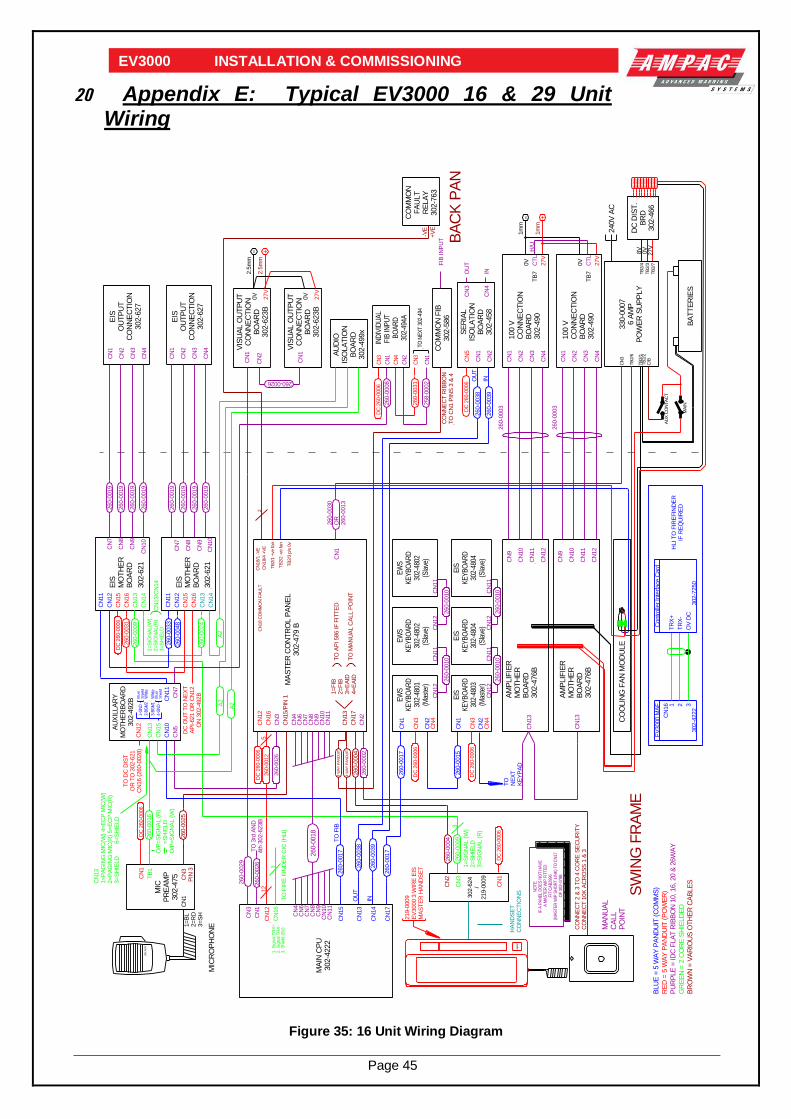
Page 45
EV3000 INSTALLATION & COMMISSIONING
20 Appendix E: Typical EV3000 16 & 29 Unit Wiring
0V
0V
BA
CK
PA
N
MIC
RO
PH
ON
E
27V
27V
302-6
21
AU
XIL
LA
RY
MO
TH
ER
BO
AR
D302-4
92B
MIC
PR
EA
MP
302-4
75
VIS
UA
L O
UT
PU
TC
ON
NE
CT
ION
BO
AR
D302-6
23B
EIS
OU
TP
UT
CO
NN
EC
TIO
N302-6
27
EIS
OU
TP
UT
CO
NN
EC
TIO
N302-6
27
A2
A2
TB
1
CN
1
CN
13
CN
5
CN
1
CN
2
CN
7
CN
8
CN
13
CN
14
CN
15
CN
3P
IN 3
CN
10
CN
11
CN
12
CN
1
CN
2
260-0
033
CN
7
EIS
MO
TH
ER
BO
AR
D
CN
15
CN
16
260-0
031
CN
12
CN
1
1=
BL
2=
RD
3=
SH
DC
260-0
006
O/P
=S
IGN
AL (
R)
=
SH
IELD
O/P
=S
IGN
AL (
W)
CN
13
1=
PA
GIN
G M
IC(W
) 4=E
CP
MIC
(W)
2=
PA
GIN
G M
IC(R
) 5=
EC
P M
IC(R
)3=
SH
IELD
6=
SH
IELD
260-0
024
1=S
IGN
AL(W
)2=S
IGN
AL(R
)3=S
HIE
LD
CN
13/C
N14
2.5
mm
2.5
mm
CN
3
CN
4
CN
9
CN
10
CN
1
CN
2
CN
3
CN
4
260-0
019
CN
11
CN
1V
ISU
AL O
UT
PU
TC
ON
NE
CT
ION
BO
AR
D302-6
23B
TO
DC
DIS
TO
R T
O 3
02-6
21
CN
16 (
260-0
028)
302-6
21
CN
7
CN
8
CN
13
CN
14
CN
12
EIS
MO
TH
ER
BO
AR
D
CN
15
CN
16
CN
9
CN
10
CN
11
DC
OU
T T
O N
EX
TA
PI-
621 O
R C
N12
ON
302-4
92B
D090
PHI
LIPS
+-
BLU
E =
5 W
AY
PA
ND
UIT
(C
OM
MS
)
RE
D =
5 W
AY
PA
ND
UIT
(P
OW
ER
)
PU
RP
LE
= ID
C F
LA
T R
IBB
ON
10, 16, 20 &
26W
AY
GR
EE
N =
2 C
OR
E S
HIE
LD
ED
BR
OW
N =
VA
RIO
US
OT
HE
R C
AB
LE
S
260-0026
260-0
019
260-0
019
260-0
019
260-0
019
260-0
019
260-0
019
260-0
019
DC
260-0
006
AU
DIO
ISO
LA
TIO
NB
OA
RD
302-4
99x
CN
1
MA
ST
ER
CO
NT
RO
L P
AN
EL
302-4
79 B
CN
2
CN
3
CN
4
CN
11
CN
10
CN
9C
N8
CN
7C
N6
CN
17
CN
15/P
IN 1
CN
13
CN
12
CN
16
1=
FIB
2=
FIB
3=
EA
ID4=
EA
ID
TO
AP
I 586 IF
FIT
TE
D
TO
MA
NU
AL C
ALL P
OIN
T
TB
2/1
+ve
fan
TB
2/2
-ve
fan
TB
2/3
p/s
0v
CO
MM
ON
FIB
302-5
86
SE
RIA
LIS
OLA
TIO
NB
OA
RD
302-4
58
CN
1
CN
2
CN
5C
N3
CN
4
OU
T
IN
FIB
IN
PU
T
EW
SK
EY
BO
AR
D30
2-48
01(M
aste
r)
EW
SK
EY
BO
AR
D30
2-48
02(S
lave
)
EIS
KE
YB
OA
RD
302-
4803
(Mas
ter)
EIS
KE
YB
OA
RD
302-
4804
(Sla
ve)
CN
12
CN
11
CN
1
CN
2
CN
1
CN
11
CN
12
CN
2
CN
3
CN
4
CN
3
CN
4
260-0
010
260-0
010
260-0
003
OU
T
IN
CO
NN
EC
T R
IBB
ON
TO
CN
1 P
INS
3 &
4
DC
260-0
006
SW
ING
FR
AM
E
TO
NE
XT
KE
YP
AD
CN
3
HA
ND
SE
TC
ON
NE
CT
ION
S
CN
2
MA
NU
AL
CA
LL
PO
INT
CN
1
1=
SIG
NA
L (
W)
2=
SH
IELD
3=
SIG
NA
L (
R)
CO
NN
EC
T 2
& 3
TO
4 C
OR
E S
EC
UR
ITY
CO
NN
EC
T 1
0K
AC
RO
SS
1 &
3
302-6
24
/219-0
009
DC
260-0
006
DC
260-0
006
DC
260-0
006
3260-0
009
260-0
004
4 W
AY
PA
ND
UIT
OU
T
IN
260-0
038
260-0
026
TO
3rd
AN
D4th
302-6
23B
260-0
002
DC
260-0
006
260-0
026
260-0
004
4 W
AY
PA
ND
UIT
260-0
039
260-0
038
260-0
039
0V
0V
27V
27V
CO
OLIN
G F
AN
MO
DU
LE
100 V
CO
NN
EC
TIO
NB
OA
RD
302-4
90
100 V
CO
NN
EC
TIO
NB
OA
RD
302-4
90
AM
PLIF
IER
MO
TH
ER
BO
AR
D302-4
76B
AM
PLIF
IER
MO
TH
ER
BO
AR
D302-4
76B
CN
13
CN
13
CN
9
CN
10
CN
11
CN
12
CN
1
CN
2
CN
3
CN
4
TB
7
CN
4
CN
3
CN
2
CN
1
CN
12
CN
11
CN
10
CN
9
CT
L
CT
L
260-0
003
H/U
1m
m
1m
m+-
TB
7
330-0
007
6 A
MP
PO
WE
R S
UP
PLY
8V
0V
27V
DC
DIS
T.
BR
D302-4
66
DC
-DIS
TD
C-D
IST
DC
-DIS
T
DC
-DIS
T
DC
-DIS
T
DC
-DIS
T
DC
-DIS
T
DC
-DIS
TD
C-D
IST
BA
TT
ER
IES
240V
AC
TB
2/4
TB
2/3
TB
2/7
CN
3
TB
2/6
TB
2/1
TB
2/2
C/B
AU
X C
ON
TA
CT
MA
IN
260-0
030
OR
260-0
013
CN
6C
N7
CN
8C
N9
CN
10
CN
11
CN
4
CN
16
CN
17
CN
13
CN
14
MA
IN C
PU
302-4
222
CN
12
CN
3
CN
1
EW
SK
EY
BO
AR
D30
2-48
02(S
lave
)
EIS
KE
YB
OA
RD
302-
4804
(Sla
ve)
CN
12
CN
11
CN
11
CN
12
260-0
010
260-0
010
4-G
ND
2-B
GM
2W
hite
1-G
ND
3-B
GM
1
Blu
e/
Shie
ld
Whi
teB
lue/
Shie
ld
260-0
009
219-0
009
EV
3000 3
WIR
E E
ISM
AS
TE
R H
AN
DS
ET
260-0
017
260-0
012
512
A2
260-0
048
260-0
025
260-0
016
260-0
017
260-0
015
260-0
018
TO
NE
XT
302
-494
IND
IVID
UA
LF
IB IN
PU
T B
OA
RD
302-
494A
CN
1
CN
2
CN
1
CN
3
CN
3
CN
4
DC
260-0
006
260-0
008
258-0
002
260-0
031
CN
15
260-0
017
CN
16 1 2 3
302-4
222
TR
X+
TR
X-
OV
DC
302-7
250
Contr
olle
r In
terf
ace
Card
HLI T
O F
IRE
FIN
DE
RIF
RE
QU
IRE
D
EV
3000 M
AF
260-0
029
AM
PA
C
TO
FIR
E F
IND
ER
CIC
(H
LI)
TO
FIB
+V
E
-VE
CO
MM
ON
FA
ULT
RE
LA
Y302-7
63
CN
18 C
OM
MO
N F
AU
LT
CN
18/1
-V
E
CN
18/4
+V
E
1. S
ignal T
RX
+2. S
ignal T
RX
-3. S
hie
ld (
0V
)
3
2
NO
TE
: IF
A P
AN
EL
DO
ES
NO
T H
AV
E
A M
AS
TE
R W
IP F
ITT
ED
FIT
CA
B29
96(M
AS
TE
R W
IP S
HO
RT
LIN
K)
TO
CN
17
OF
302
-479
B
Figure 35: 16 Unit Wiring Diagram
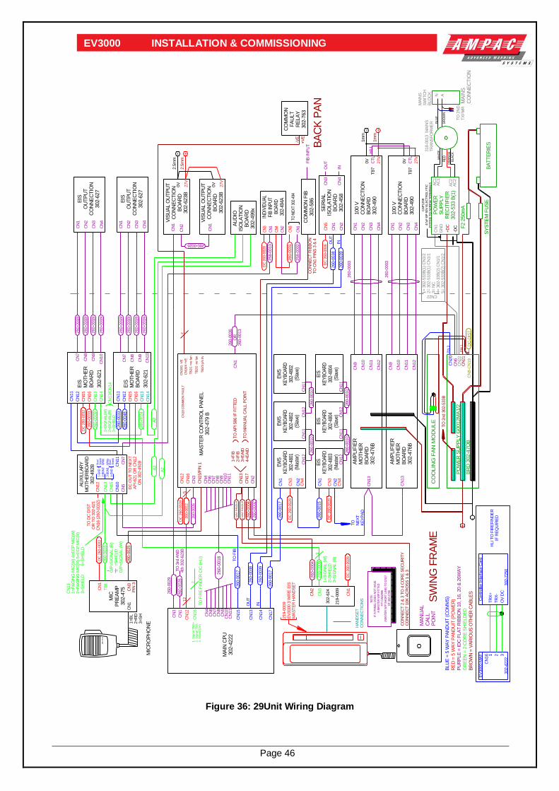
Page 46
EV3000 INSTALLATION & COMMISSIONING
0V
0V
BA
CK
PA
N
MIC
RO
PH
ON
E
27V
27V
302-6
21
AU
XIL
LA
RY
MO
TH
ER
BO
AR
D302-4
92B
MIC
PR
EA
MP
302-4
75
VIS
UA
L O
UT
PU
TC
ON
NE
CT
ION
BO
AR
D302-6
23B
EIS
OU
TP
UT
CO
NN
EC
TIO
N302-6
27
EIS
OU
TP
UT
CO
NN
EC
TIO
N302-6
27
A2
A2
TB
1
CN
1
CN
13
CN
5
CN
1
CN
2
CN
7
CN
8
CN
13
CN
14
CN
15
CN
3P
IN 3
CN
10
CN
11
CN
12
CN
1
CN
2
260-0
033
CN
7
EIS
MO
TH
ER
BO
AR
D
CN
15
CN
16
260-0
031
CN
12
CN
1
1=B
L2=R
D3=S
H
DC
260-0
032
O/P
=S
IGN
AL (
R)
=S
HIE
LD
O/P
=S
IGN
AL (
W)
CN
13
1=P
AG
ING
MIC
(W)
4=E
CP
MIC
(W)
2=P
AG
ING
MIC
(R)
5=E
CP
MIC
(R)
3=S
HIE
LD
6=S
HIE
LD
260-0
024
1=S
IGN
AL(W
)2=S
IGN
AL(R
)3=S
HIE
LD
CN
13/C
N14
2.5
mm
2.5
mm
CN
3
CN
4
CN
9
CN
10
CN
1
CN
2
CN
3
CN
4
260-0
019
CN
11
CN
1V
ISU
AL O
UT
PU
TC
ON
NE
CT
ION
BO
AR
D302-6
23B
TO
DC
DIS
TO
R T
O 3
02-6
21
CN
16 (
260-0
032)
302-6
21
CN
7
CN
8
CN
13
CN
14
CN
12
EIS
MO
TH
ER
BO
AR
D
CN
15
CN
16
CN
9
CN
10
CN
11
DC
OU
T T
O N
EX
TA
PI-
621 O
R C
N12
ON
302-4
92B
D090
PHI
LIPS
+-
BLU
E =
5 W
AY
PA
ND
UIT
(C
OM
MS
)
RE
D =
5 W
AY
PA
ND
UIT
(P
OW
ER
)
PU
RP
LE
= ID
C F
LA
T R
IBB
ON
10, 16, 20 &
26W
AY
GR
EE
N =
2 C
OR
E S
HIE
LD
ED
BR
OW
N =
VA
RIO
US
OT
HE
R C
AB
LE
S
260-0026
260-0
019
260-0
019
260-0
019
260-0
019
260-0
019
260-0
019
260-0
019
DC
260-0
032
AU
DIO
ISO
LA
TIO
NB
OA
RD
302-4
99x
CN
1
MA
ST
ER
CO
NT
RO
L P
AN
EL
302-4
79 B
CN
2
CN
3
CN
4
CN
11
CN
10
CN
9C
N8
CN
7C
N6
CN
17
CN
15/P
IN 1
CN
13
CN
12
CN
16
1=F
IB2=F
IB3=E
AID
4=E
AID
TO
AP
I 586 IF
FIT
TE
D
TO
MA
NU
AL C
ALL P
OIN
T
TB
2/1
+ve
fan
TB
2/2
-ve
fan
TB
2/3
p/s
0v
CO
MM
ON
FIB
302-5
86
SE
RIA
LIS
OLA
TIO
NB
OA
RD
302-4
58
CN
1
CN
2
CN
5C
N3
CN
4
OU
T
IN
FIB
IN
PU
T
EW
SK
EY
BO
AR
D30
2-48
01(M
aste
r)
EW
SK
EY
BO
AR
D30
2-48
02(S
lave
)
EIS
KE
YB
OA
RD
302-
4803
(Mas
ter)
EIS
KE
YB
OA
RD
302-
4804
(Sla
ve)
CN
12
CN
11
CN
1
CN
2
CN
1
CN
11
CN
12
CN
2
CN
3
CN
4
CN
3
CN
4
260-0
010
260-0
010
260-0
003
OU
T
IN
CO
NN
EC
T R
IBB
ON
TO
CN
1 P
INS
3 &
4
DC
260-0
006
SW
ING
FR
AM
E
TO
NE
XT
KE
YP
AD
CN
3
HA
ND
SE
TC
ON
NE
CT
ION
S
CN
2
MA
NU
AL
CA
LL
PO
INT
CN
1
1=S
IGN
AL (
W)
2=S
HIE
LD
3=S
IGN
AL (
R)
CO
NN
EC
T 2
& 3
TO
4 C
OR
E S
EC
UR
ITY
CO
NN
EC
T 1
0K
AC
RO
SS
1 &
3
302-6
24
/219-0
009
AM
PA
C
DC
260-0
028
DC
260-0
028
DC
260-0
028
3260-0
009
260-0
004
4 W
AY
PA
ND
UIT
OU
T
IN
260-0
038
260-0
026
TO
3rd
AN
D4th
302-6
23B
260-0
002
DC
260-0
028
260-0
026
260-0
004
4 W
AY
PA
ND
UIT
260-0
039
260-0
038
260-0
039
0V
0V
27V
27V
100 V
CO
NN
EC
TIO
NB
OA
RD
302-4
90
100 V
CO
NN
EC
TIO
NB
OA
RD
302-4
90
AM
PLIF
IER
MO
TH
ER
BO
AR
D302-4
76B
AM
PLIF
IER
MO
TH
ER
BO
AR
D302-4
76B
CN
13
CN
13
CN
9
CN
10
CN
11
CN
12
CN
1
CN
2
CN
3
CN
4
TB
7
CN
4
CN
3
CN
2
CN
1
CN
12
CN
11
CN
10
CN
9
CT
L
CT
L
260-0
003
H/U
1m
m
1m
m+-
TB
7
260-0
036
OR
260-0
013
CN
6C
N7
CN
8C
N9
CN
10
CN
11
CN
4
CN
17
CN
13
CN
14
MA
IN C
PU
302-4
222
CN
12
CN
3
CN
1
EW
SK
EY
BO
AR
D30
2-48
02(S
lave
)
EIS
KE
YB
OA
RD
302-
4804
(Sla
ve)
CN
12
CN
11
CN
11
CN
12
260-0
010
260-0
010
4-G
ND
2-B
GM
2W
hite
1-G
ND
3-B
GM
1
Blu
e/
Shie
ld
Whi
teB
lue/
Shie
ld
260-0
009
219-0
009
EV
3000 3
WIR
E E
ISM
AS
TE
R H
AN
DS
ET
260-0
017
260-0
012
512
A2
260-0
048
260-0
025
260-0
016
260-0
017
260-0
015
260-0
018
TO N
EX
T 30
2-49
4
IND
IVID
UA
LF
IB IN
PU
T
BO
AR
D30
2-49
4A
CN
1
CN
2
CN
1
CN
3
CN
3
CN
4
DC
260-0
028
258-0
013
258-0
002
260-0
031
CN
15
260-0
017
CN
16 1 2 3
302-4
222
TR
X+
TR
X-
OV
DC
302-7
250
Contr
olle
r In
terf
ace
Card
HLI T
O F
IRE
FIN
DE
RIF
RE
QU
IRE
D
EV
3000 M
AF
260-0
029
-DC
+
-
AC
1
AC
2
318-0
013 M
AIN
ST
RA
NS
FO
RM
ER
MA
INS
SW
ITC
HB
LO
CK AN
CN
22
CN
1
MA
INS
CO
NN
EC
TIO
N
+D
CC
N20
TO
2nd 3
02-5
33B
CN
21
PO
WE
RS
UP
PLY
RE
CIT
IFIE
R302-5
33 B
(1)
CO
OLIN
G F
AN
MO
DU
LE
PO
WE
R S
UP
PLY
G0012M
A1/2
BR
D 3
02-4
7O
B
BA
TT
ER
IES
SY
ST
EM
FU
SE
F2 2
50m
A
CN
6
CN
8-C
N19
DC
-DIS
T
TO
2N
DT
XF
MR
1= 3
02-5
33B
(1)
CN
1/2
2= 3
02-5
33B
(1)
CN
1/1
3= N
C4= 3
02-3
3B
(2)
CN
1/1
5= 3
02-5
33B
(2)
CN
1/2
CN22
PIN
1
PIN
3
TO
FIB
+V
E
-VE
CO
MM
ON
FA
ULT
RE
LA
Y302-7
63
CN
18 C
OM
MO
N F
AU
LT
CN
18/1
-V
E
CN
18/4
+V
E
CN
16
TO
FIR
E F
IND
ER
CIC
(H
LI)
1. S
ignal T
RX
+2. S
ignal T
RX
-3. S
hie
ld (
0V
)
3
2
AC
1
AC
2
WH
ITE
RE
DO
RA
NG
EB
LA
CK
BLU
E
BR
OW
NG
ND
CA
P1208
47uF
BP
50V
ELE
CT
RO
LY
TIC
FIT
TE
D T
O S
CR
EW
TE
RM
INA
LS
NO
TE
: IF
A P
AN
EL
DO
ES
NO
T H
AV
E
A M
AS
TE
R W
IP F
ITT
ED
FIT
CA
B29
96(M
AS
TE
R W
IP S
HO
RT
LIN
K)
TO
CN
17
OF
302
-479
B
Figure 36: 29Unit Wiring Diagram

Page 47
EV3000 INSTALLATION & COMMISSIONING
21 Glossary Of Terms
ACKD : ACKNOWLEDGED
ALM : ALARM
BGM : BACKGROUND MUSIC
C : RELAY COMMON CONTACT (WIPER)
CN : CONNECTOR
CPU : COMMON PROCESSOR UNIT
DCV : DIRECT CURRENT VOLTS
EAID : EMERGENCY ALARM INITIATING DEVICE
EARTH: BUILDING EARTH
ECP : EMERGENCY CONTROL PANEL
OIS : OCCUPANT INTERCOMMUNICATION SYSTEM
EOL : END OF LINE
OWIS : OCCUPANT WARNING AND INTERCOMMUNICATION SYSTEM
OWS : OCCUPANT WARNING SYSTEM
FACP : FIRE ALARM CONTROL PANEL
FLT : FAULT
GND : GROUND (0 VOLTS) NOT EARTH
GPO : GENERAL PURPOSE OUTLET
I/O : INPUT/OUTPUT
ISOL : ISOLATED
MAF : MASTER ALARM FACILITY
MCB : MASTER CONTROL BOARD
MCP : MANUAL CALL POINT
MECP : MASTER EMERGENCY CONTROL PANEL
MOV : METAL OXIDE VARISTOR (TRANSIENT PROTECTION)
N/C : NORMALLY CLOSED RELAY CONTACTS
N/O : NORMALLY OPENED RELAY CONTACTS
PA : PUBLIC ADDRESS
PCB : PRINTED CIRCUIT BOARDS
PRIN : PRINTER
P/S : POWER SUPPLY
PSM : POWER SUPPLY MODULE
REM : REMOTE
SECP : SECONDARY EMERGENCY CONTROL PANEL
TB : TERMINAL BLOCK
SGM : SIGNAL GENERATOR MODULE
VDU : VIDEO DISPLAY UNIT
WIP : WARDEN INTERCOM POINT

Page 48
EV3000 INSTALLATION & COMMISSIONING
22 Definitions
Activating device - a device capable of being operated automatically or manually to initiate an alarm signal, e.g. a detector, a manual call point, or a pressure switch.
Alarm system - facility provided in a building to give an alarm in the event of fire, civil commotion, bomb threat, leakage of toxic or noxious fumes, structural damage, or other emergency.
Alarm signal - a signal given by fire alarm, or other alarm system, at the fire indicator panel (FACP) or other panel to alert wardens and other nominated personnel as necessary to commence prescribed actions.
Alarm zone - the specific portion of a building or complex identified by a particular alarm zone facility.
Alert signal - an audible signal, or combination of audible and visible signals, from the Occupant warning system to alert wardens and other nominated personnel as necessary to commence prescribed actions.
Approved and approval - approved by, or the approval of, the Regulatory Authority concerned.
Control and indicating equipment (CIE) - a combination of control equipment and indicating equipment.
Control equipment - equipment which controls the receipts and transmission of signals within the fire detection and alarm system or initiates other action.
Emergency alarm initiating device - a manually operated device by which an alarm is given to indicate an emergency.
Emergency condition - is a condition which requires the evacuation of the building or zone.
Emergency control panel (ECP) - a panel by means of which the occupant warning system and the occupant intercommunication system (if any) in the building may be operated [NOTE: see also definition of master emergency control panel (MECP)].
Occupant intercommunication system (OIS) - a two-way system which provides voice communication between the controlling emergency control panel (ECP) and the warden intercommunication points (WIPS).
Occupant warning and intercommunication system (OWIS) - a combined occupant warning and intercommunication system.
Occupant warning system (OWS) - a system to provide a distinctive audible signal, verbal address, and visible signals as required, during an emergency condition.
Evacuation sequence - a pre-programmed sequence initiating alert and evacuation signals to evacuation zones as required by the Regulations Authority.
Evacuation signal - an audible signal, or combination of audible signals, from the occupant warning system to indicate to wardens and building occupants generally that an evacuation or other prescribed actions are necessary.
Evacuation zone - a specific portion of a building or complex, in which the evacuation procedures are managed by one zone warden. [NOTE: this term should not be confused with the concept of 'fire alarm zone'. Fire alarm zone may or may not cover the same area as an evacuation zone.]
Factory connections - are connections made during manufacture and should not require any field alterations.
Field connections - are connections made to FACP or ancillary equipment at the project during installation.
Firmware - the basic operating program which is not intended to be field changeable.
House warden - a person who, during an emergency, assumes control over the building and its occupants and is the prime contact with the appropriate emergency services(s).
Interface - The interconnection between equipment which permits the transfer of data.

Page 49
EV3000 INSTALLATION & COMMISSIONING
Main equipment - equipment essential to the operation of the system including, control equipment, amplification equipment and power supply modules.
Master alarm facility (MAF) - that part of the control and indicating equipment which receives alarm and fault signals from any alarm zone facility and initiates the common signal (alarm and/or fault) for transmission to the fire control station where appropriate. Bells and other ancillary functions may be initiated from this facility.
Master emergency control panel (MECP) - a specially designated emergency control panel (ECP) that on manual operation of its key switch, takes full control of the occupant warning system and the occupant intercommunication system, and overrides all other ECP’s in the building.
Power Supply - that portion of the control and indicating equipment (CIE) which supplies all voltages necessary for operation of the CIE.
Regulatory Authority - an authority administering Acts of Parliament or Regulations under such Acts.
Remote auxiliary supply - power supply DC24VDC max from a remote source.
Verbal address - the mode of operation whereby verbal instruction is given from the controlling emergency control panel (ECP) to the building occupants via the loud speaker systems.
Warden intercommunication point (WIP) - the location on a floor or evacuation zone, where equipment is provided through which instructions can be received from the controlling emergency control panel (ECP) via the occupant intercommunication system.
Zone (floor) warden - a person who, during an emergency, assumes control over a particular floor or evacuation zone under the direction of the house warden.
UNCONTROLLED DOCUMENT
NOTE: Due to Ampac’s commitment to continuous improvement specifications may change without notice.