european technical eta-11/0141 assessment of 08/08/2016 · en iso 10684 material 1.4401, 1.4404,...
TRANSCRIPT

INSTYTUT TECHNIKI BUDOWLANEJ
PL 00-611 WARSZAWA ul. Filtrowa 1 tel.: (+48 22) 825-04-71 (+48 22) 825-76-55 fax: (+48 22) 825-52-86 www.itb.pl
European Technical Assessment
ETA-11/0141 of 08/08/2016
(English language translation – the original version is in Polish language)
General Part
Technical Assessment Body issuing the European Technical Assessment
Instytut Techniki Budowlanej
Trade name of the construction product RAWL RP-30 / RAWL R-KF2
Product family to which the construction product belongs
Bonded anchor with anchor rod made of galvanized steel or stainless steel for use in non-cracked concrete
Manufacturer
RAWLPLUG S.A. ul. Kwidzyńska 6 51-416 Wrocław, Poland
Manufacturing plant Manufacturing Plant no. 3
This European Technical Assessment contains
16 pages including 3 Annexes which form an integral part of this Assessment
This European Technical Assessment is issued in accordance with Regulation (EU) No 305/2011, on the basis of
This version replaces
Guideline for European Technical Approval ETAG 001, Edition April 2013 “Metal anchors for use in concrete – Part 1: Anchors in general and Part 5: Bonded anchors”, used as European Assessment Document (EAD)
ETA-11/0141 issued on 28/06/2013
®
Page 2 of European Technical Assessment ETA-11/0141, issued on 08/08/2016
This European Technical Assessment is issued by the Technical Assessment Body in its official language. Translations of this European Technical Assessment in other languages shall fully correspond to the original issued document and should be identified as such.
Communication of this European Technical Assessment, including transmission by electronic means, shall be in full. However, partial reproduction may be made, with the written consent of the issuing Technical Assessment Body. Any partial reproduction has to be identified as such.
Page 3 of European Technical Assessment ETA-11/0141, issued on 08/08/2016
Specific Part
1 Technical description of the product
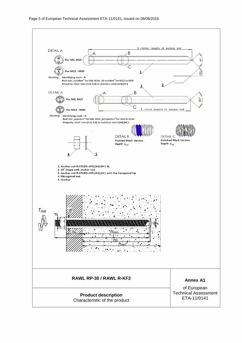
This European Technical Assessment applies to the following products’ trade names: RAWL RP30 and RAWL R-KF2. RAWL RP-30 / RAWL R-KF2 is bonded anchor (injection type) consisting of a injection mortar cartridge using an applicator gun equipped with a special mixing nozzle and threaded anchor rod of the sizes M8 to M30 made of:
– galvanized carbon steel,
– stainless steel,
– high corrosion resistant stainless steel,
with hexagon nut and washer.
The threaded rod is placed into a drilled hole previously injected (using an applicator gun) with a mortar with a slow and slight twisting motion. The threaded rod is anchored by the bond between rod, mortar and concrete.
The threaded rods are available for all diameters with three type of tip end: a one side 45° chamfer, a two sides 45° chamfer or a flat. The threaded rods are either delivered with the mortar cartridges or commercial standard threaded rods purchased separately. The mortar cartridges are available in different sizes and types.
An illustration and the description of the products are given in Annexes A.
2 Specification of the intended use in accordance with the applicable European Assessment Document (EAD)
The performances given in Section 3 are only valid if the anchors are used in compliance with the specifications and conditions given in Annexes B.
The performances given in this European Technical Assessment are based on an assumed working life of the anchor of 50 years. The indications given on the working life cannot be interpreted as a guarantee given by the producer or the Technical Assessment Body, but are to be regarded only as a means for choosing the right products in relation to the expected economically reasonable working life of the works.
3 Performance of the product and references to the methods used for its assessment
3.1 Performance of the product
3.1.1 Mechanical resistance and stability (BWR 1)
The essential characteristic is detailed in the Annexes C.
3.1.2 Safety in case of fire (BWR 2)
Essential characteristics Performances
Reaction to fire Anchorages satisfy requirements for Class A1
Resistance to fire No performance assessed
Page 4 of European Technical Assessment ETA-11/0141, issued on 08/08/2016
3.1.3 Hygiene, health and the environment (BWR 3)
Regarding the dangerous substances there may be requirements applicable to the products falling within its scope (e.g. transposed European legislation and national laws, regulations and administrative provisions). In order to meet the provisions of the Construction Products Regulation, these requirements need also to be complied with, when and where they apply.
3.1.4 Safety and accessibility in use (BWR 4)
For Basic Requirement Safety in use the same criteria are valid as for Basic Requirement Mechanical resistance and stability (BWR 1).
3.1.5 Sustainable use of natural resources (BWR 7)
No performance assessed.
3.2 Methods used for the assessment
The assessment of fitness of the anchors for declared intended use in relation to the requirements for mechanical resistance and stability and safety in use in the sense of the Basic Requirements 1 and 4 has been made in accordance with the ETAG 001 “Metal anchors for use in concrete”, Part 1: “Anchors in general” and Part 5: “Bonded anchors”, on the basis of Option 7.
4 Assessment and verification of constancy of performance (AVCP) system applied, with reference to its legal base
According to Decision 96/582/EC of the European Commission the system of assessment and verification of constancy of performance (see Annex V to Regulation (EU) No 305/2011) given in the following table applies.
Product Intended use Level or class System
Metal anchors for use in concrete
For fixing and/or supporting to concrete structural elements (which contributes to the stability of the works) or heavy units
1
5 Technical details necessary for the implementation of the AVCP system, as provided for in the applicable European Assessment Document (EAD)
Technical details necessary for the implementation of the AVCP system are laid down in the control plan which is deposited at Instytut Techniki Budowlanej.
For type testing the results of the tests performed as part of the assessment for the European Technical Assessment shall be used unless there are changes in the production line or plant. In such cases the necessary type testing has to be agreed between Instytut Techniki Budowlanej and the notified body.
Issued in Warsaw on 08/08/2016 by Instytut Techniki Budowlanej
Marcin M. Kruk,
Director of ITB
Page 5 of European Technical Assessment ETA-11/0141, issued on 08/08/2016
RAWL RP-30 / RAWL R-KF2 Annex A1
of European Technical Assessment
ETA-11/0141 Product description
Characteristic of the product
Page 6 of European Technical Assessment ETA-11/0141, issued on 08/08/2016
RAWL RP-30 / RAWL R-KF2 Annex A2
of European Technical Assessment
ETA-11/0141 Product description
Materials
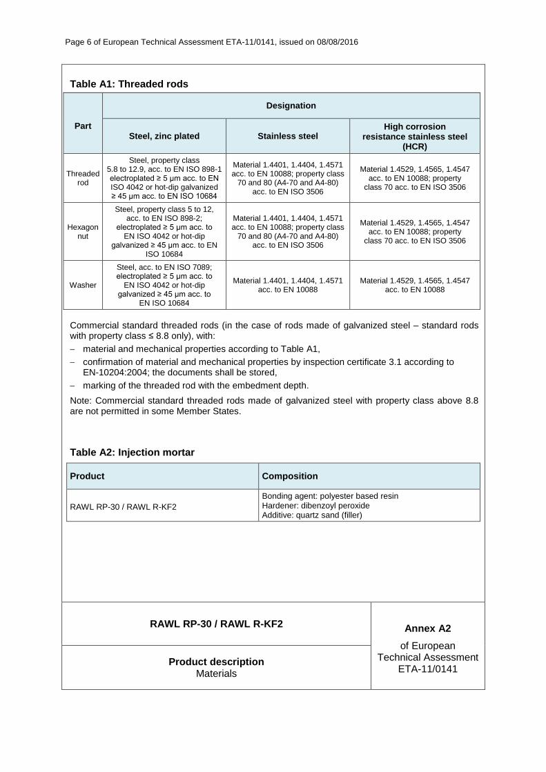
Table A1: Threaded rods
Part
Designation
Steel, zinc plated Stainless steel High corrosion
resistance stainless steel (HCR)
Threaded rod
Steel, property class 5.8 to 12.9, acc. to EN ISO 898-1 electroplated ≥ 5 µm acc. to EN ISO 4042 or hot-dip galvanized ≥ 45 µm acc. to EN ISO 10684
Material 1.4401, 1.4404, 1.4571 acc. to EN 10088; property class
70 and 80 (A4-70 and A4-80) acc. to EN ISO 3506
Material 1.4529, 1.4565, 1.4547 acc. to EN 10088; property
class 70 acc. to EN ISO 3506
Hexagon nut
Steel, property class 5 to 12, acc. to EN ISO 898-2;
electroplated ≥ 5 µm acc. to EN ISO 4042 or hot-dip
galvanized ≥ 45 µm acc. to EN ISO 10684
Material 1.4401, 1.4404, 1.4571 acc. to EN 10088; property class
70 and 80 (A4-70 and A4-80) acc. to EN ISO 3506
Material 1.4529, 1.4565, 1.4547 acc. to EN 10088; property
class 70 acc. to EN ISO 3506
Washer
Steel, acc. to EN ISO 7089; electroplated ≥ 5 µm acc. to
EN ISO 4042 or hot-dip galvanized ≥ 45 µm acc. to
EN ISO 10684
Material 1.4401, 1.4404, 1.4571 acc. to EN 10088
Material 1.4529, 1.4565, 1.4547 acc. to EN 10088
Commercial standard threaded rods (in the case of rods made of galvanized steel – standard rods with property class ≤ 8.8 only), with:
material and mechanical properties according to Table A1,
confirmation of material and mechanical properties by inspection certificate 3.1 according to EN-10204:2004; the documents shall be stored,
marking of the threaded rod with the embedment depth.
Note: Commercial standard threaded rods made of galvanized steel with property class above 8.8 are not permitted in some Member States.
Table A2: Injection mortar
Product Composition
RAWL RP-30 / RAWL R-KF2
Bonding agent: polyester based resin Hardener: dibenzoyl peroxide Additive: quartz sand (filler)

Page 7 of European Technical Assessment ETA-11/0141, issued on 08/08/2016
RAWL RP-30 / RAWL R-KF2 Annex A3
of European Technical Assessment
ETA-11/0141 Product description
Cartridge types and sizes
Page 8 of European Technical Assessment ETA-11/0141, issued on 08/08/2016
RAWL RP-30 / RAWL R-KF2 Annex B1
of European Technical Assessment
ETA-11/0141 Intended use Intended use
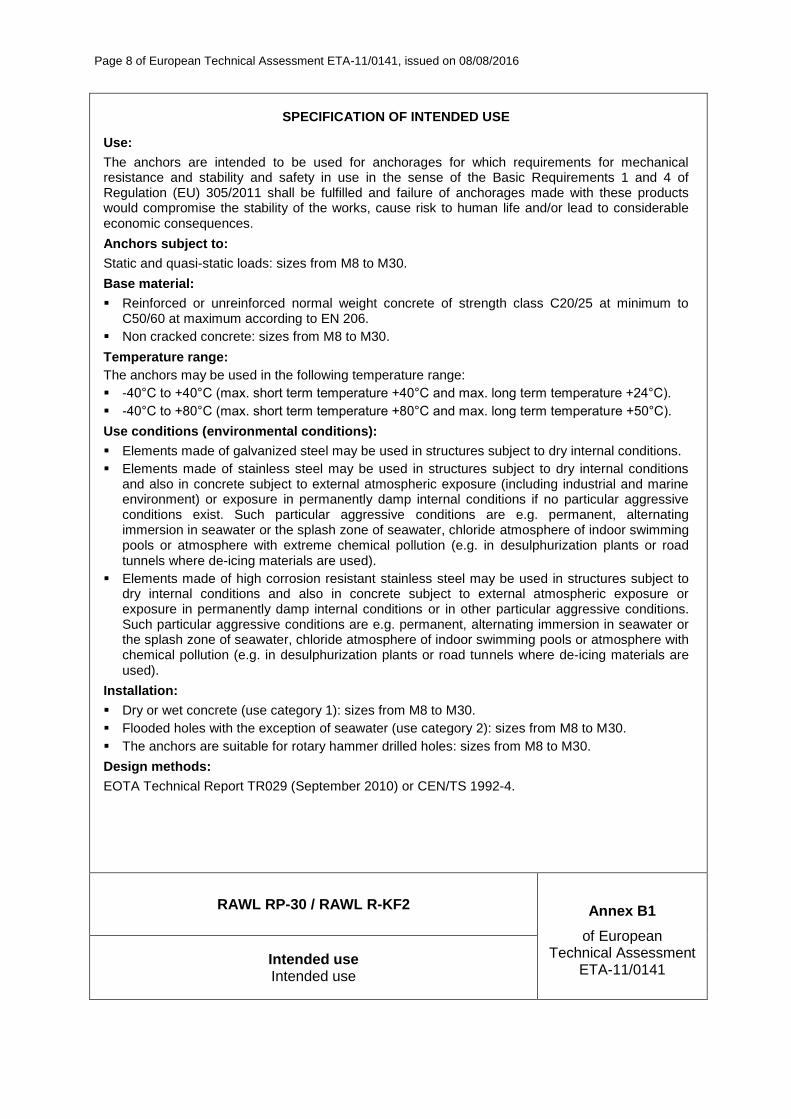
SPECIFICATION OF INTENDED USE
Use:
The anchors are intended to be used for anchorages for which requirements for mechanical resistance and stability and safety in use in the sense of the Basic Requirements 1 and 4 of Regulation (EU) 305/2011 shall be fulfilled and failure of anchorages made with these products would compromise the stability of the works, cause risk to human life and/or lead to considerable economic consequences.
Anchors subject to:
Static and quasi-static loads: sizes from M8 to M30.
Base material:
Reinforced or unreinforced normal weight concrete of strength class C20/25 at minimum to C50/60 at maximum according to EN 206.
Non cracked concrete: sizes from M8 to M30.
Temperature range:
The anchors may be used in the following temperature range:
-40°C to +40°C (max. short term temperature +40°C and max. long term temperature +24°C).
-40°C to +80°C (max. short term temperature +80°C and max. long term temperature +50°C).
Use conditions (environmental conditions):
Elements made of galvanized steel may be used in structures subject to dry internal conditions.
Elements made of stainless steel may be used in structures subject to dry internal conditions and also in concrete subject to external atmospheric exposure (including industrial and marine environment) or exposure in permanently damp internal conditions if no particular aggressive conditions exist. Such particular aggressive conditions are e.g. permanent, alternating immersion in seawater or the splash zone of seawater, chloride atmosphere of indoor swimming pools or atmosphere with extreme chemical pollution (e.g. in desulphurization plants or road tunnels where de-icing materials are used).
Elements made of high corrosion resistant stainless steel may be used in structures subject to dry internal conditions and also in concrete subject to external atmospheric exposure or exposure in permanently damp internal conditions or in other particular aggressive conditions. Such particular aggressive conditions are e.g. permanent, alternating immersion in seawater or the splash zone of seawater, chloride atmosphere of indoor swimming pools or atmosphere with chemical pollution (e.g. in desulphurization plants or road tunnels where de-icing materials are used).
Installation:
Dry or wet concrete (use category 1): sizes from M8 to M30.
Flooded holes with the exception of seawater (use category 2): sizes from M8 to M30.
The anchors are suitable for rotary hammer drilled holes: sizes from M8 to M30.
Design methods:
EOTA Technical Report TR029 (September 2010) or CEN/TS 1992-4.
Page 9 of European Technical Assessment ETA-11/0141, issued on 08/08/2016
RAWL RP-30 / RAWL R-KF2 Annex B2
of European Technical Assessment
ETA-11/0141 Intended use
Installation data
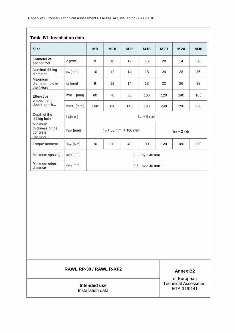
Table B1: Installation data
Size M8 M10 M12 M16 M20 M24 M30
Diameter of anchor rod
d [mm] 8 10 12 16 20 24 30
Nominal drilling diameter
d0 [mm] 10 12 14 18 24 28 35
Maximum diameter hole in the fixture
df [mm] 9 12 14 18 22 26 32
Effemctive embedment depth hef = hno
min [mm] 60 70 80 100 120 140 165
max [mm] 100 120 145 190 240 290 360
Depth of the drilling hole
h0 [mm] hef + 5 mm
Minimum thickness of the concrete memeber
hmin [mm] hef + 30 mm; ≥ 100 mm hef + 2 · d0
Torque moment Tinst [Nm] 10 20 40 80 120 180 300
Minimum spacing smin [mm] 0,5 · hef 40 mm
Minimum edge distance
cmin [mm] 0,5 · hef 40 mm
Page 10 of European Technical Assessment ETA-11/0141, issued on 08/08/2016
RAWL RP-30 / RAWL R-KF2 Annex B3
of European Technical Assessment
ETA-11/0141 Intended use
Processing time and curing time
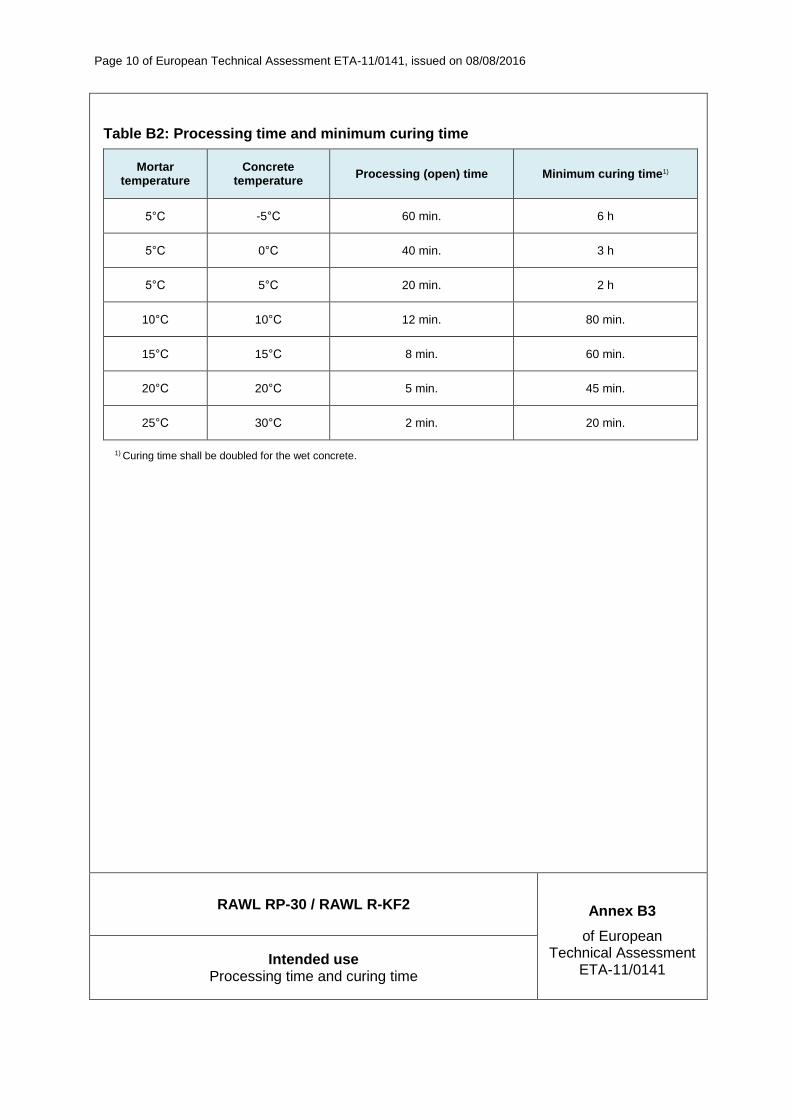
Table B2: Processing time and minimum curing time
Mortar temperature
Concrete temperature
Processing (open) time Minimum curing time1)
5°C -5°C 60 min. 6 h
5°C 0°C 40 min. 3 h
5°C 5°C 20 min. 2 h
10°C 10°C 12 min. 80 min.
15°C 15°C 8 min. 60 min.
20°C 20°C 5 min. 45 min.
25°C 30°C 2 min. 20 min.
1) Curing time shall be doubled for the wet concrete.
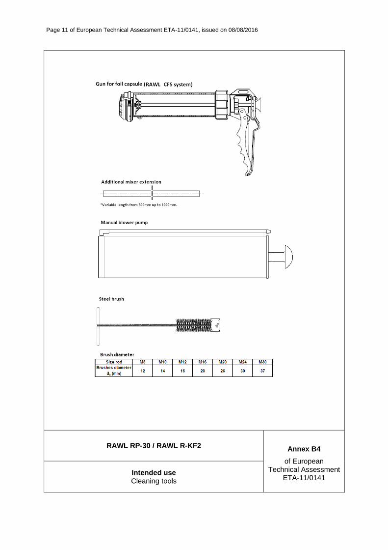
Page 11 of European Technical Assessment ETA-11/0141, issued on 08/08/2016
RAWL RP-30 / RAWL R-KF2 Annex B4
of European Technical Assessment
ETA-11/0141 Intended use Cleaning tools
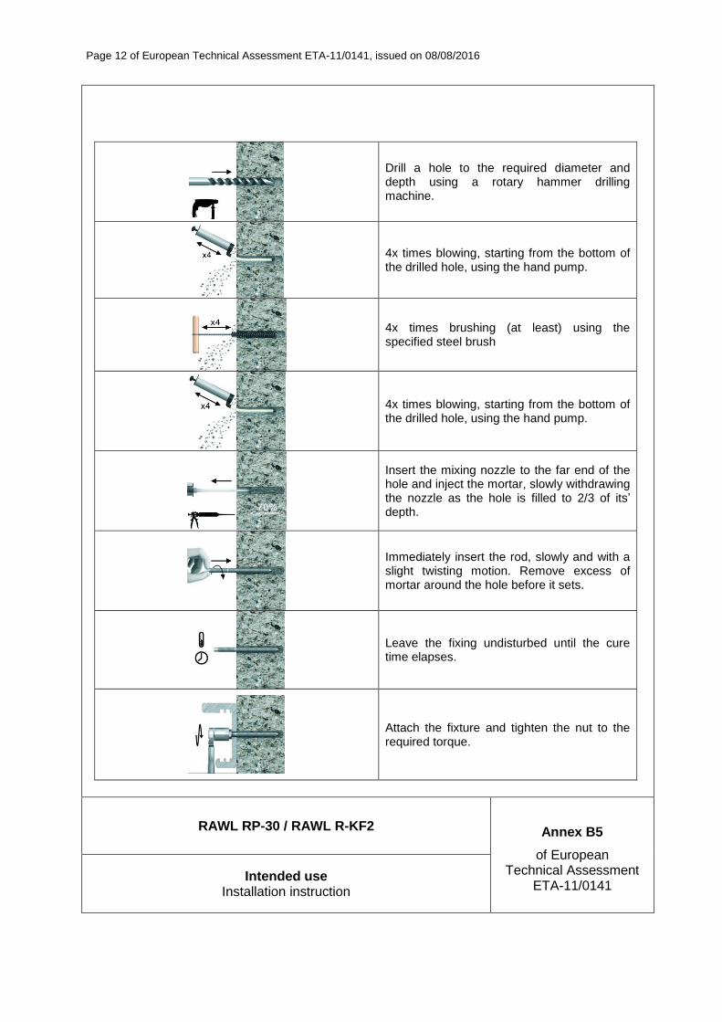
Page 12 of European Technical Assessment ETA-11/0141, issued on 08/08/2016
Drill a hole to the required diameter and depth using a rotary hammer drilling machine.
4x times blowing, starting from the bottom of the drilled hole, using the hand pump.
4x times brushing (at least) using the specified steel brush
4x times blowing, starting from the bottom of the drilled hole, using the hand pump.
Insert the mixing nozzle to the far end of the hole and inject the mortar, slowly withdrawing the nozzle as the hole is filled to 2/3 of its’ depth.
Immediately insert the rod, slowly and with a slight twisting motion. Remove excess of mortar around the hole before it sets.
Leave the fixing undisturbed until the cure time elapses.
Attach the fixture and tighten the nut to the required torque.
RAWL RP-30 / RAWL R-KF2 Annex B5
of European Technical Assessment
ETA-11/0141 Intended use
Installation instruction
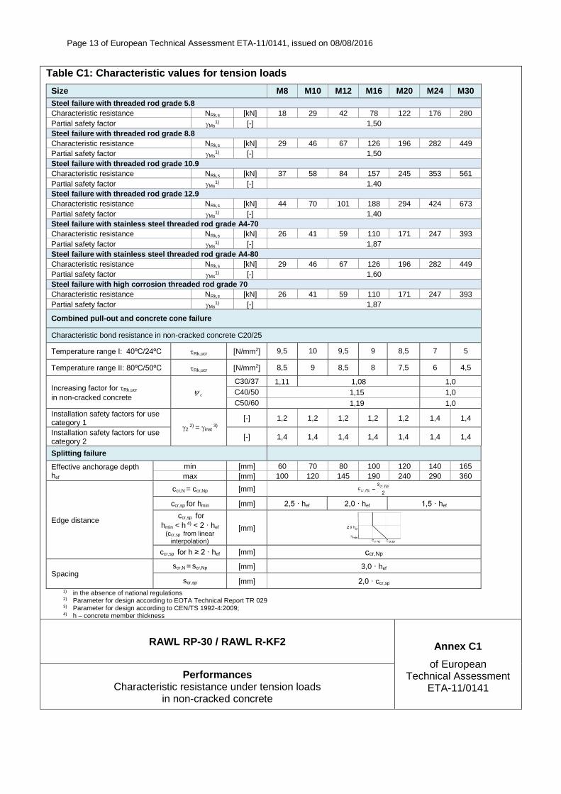
Page 13 of European Technical Assessment ETA-11/0141, issued on 08/08/2016
RAWL RP-30 / RAWL R-KF2 Annex C1
of European Technical Assessment
ETA-11/0141
Performances Characteristic resistance under tension loads
in non-cracked concrete
Table C1: Characteristic values for tension loads
Size M8 M10 M12 M16 M20 M24 M30
Steel failure with threaded rod grade 5.8
Characteristic resistance NRk,s [kN] 18 29 42 78 122 176 280
Partial safety factor Ms1) [-] 1,50
Steel failure with threaded rod grade 8.8
Characteristic resistance NRk,s [kN] 29 46 67 126 196 282 449
Partial safety factor Ms1) [-] 1,50
Steel failure with threaded rod grade 10.9
Characteristic resistance NRk,s [kN] 37 58 84 157 245 353 561
Partial safety factor Ms1) [-] 1,40
Steel failure with threaded rod grade 12.9
Characteristic resistance NRk,s [kN] 44 70 101 188 294 424 673
Partial safety factor Ms1) [-] 1,40
Steel failure with stainless steel threaded rod grade A4-70
Characteristic resistance NRk,s [kN] 26 41 59 110 171 247 393
Partial safety factor Ms1) [-] 1,87
Steel failure with stainless steel threaded rod grade A4-80
Characteristic resistance NRk,s [kN] 29 46 67 126 196 282 449
Partial safety factor Ms1) [-] 1,60
Steel failure with high corrosion threaded rod grade 70
Characteristic resistance NRk,s [kN] 26 41 59 110 171 247 393
Partial safety factor Ms1) [-] 1,87
Combined pull-out and concrete cone failure
Characteristic bond resistance in non-cracked concrete C20/25
Temperature range I: 40ºC/24ºC Rk,ucr [N/mm2] 9,5 10 9,5 9 8,5 7 5
Temperature range II: 80ºC/50ºC Rk,ucr [N/mm2] 8,5 9 8,5 8 7,5 6 4,5
Increasing factor for Rk,ucr
in non-cracked concrete c
C30/37 1,11 1,08 1,0
C40/50 1,15 1,0
C50/60 1,19 1,0
Installation safety factors for use category 1
2 2)
= inst 3)
[-] 1,2 1,2 1,2 1,2 1,2 1,4 1,4
Installation safety factors for use category 2
[-] 1,4 1,4 1,4 1,4 1,4 1,4 1,4
Splitting failure
Effective anchorage depth hef
min [mm] 60 70 80 100 120 140 165
max [mm] 100 120 145 190 240 290 360
Edge distance
ccr,N = ccr,Np [mm]
ccr,sp for hmin [mm] 2,5 · hef 2,0 · hef 1,5 · hef
ccr,sp for
hmin < h 4) < 2 · hef
(ccr,sp from linear interpolation)
[mm]
ccr,sp for h ≥ 2 · hef [mm] ccr,Np
Spacing scr,N = scr,Np [mm] 3,0 · hef
scr,sp [mm] 2,0 · ccr,sp
1) in the absence of national regulations
2) Parameter for design according to EOTA Technical Report TR 029
3) Parameter for design according to CEN/TS 1992-4:2009; 4) h – concrete member thickness
Note: Design method according to TR 029 1) See: Annex B1 2) In the absence of other national regulation

Page 14 of European Technical Assessment ETA-11/0141, issued on 08/08/2016
RAWL RP-30 / RAWL R-KF2 Annex C2
of European Technical Assessment
ETA-11/0141
Performances Characteristic resistance under tension and shear loads
in non-cracked concrete
Table C2: Shear loads for steel failure without lever arm
Size M8 M10 M12 M16 M20 M24 M30
Steel failure with threaded rod grade 5.8
Characteristic resistance VRk,s [kN] 9 14 21 39 61 88 140
Partial safety factor Ms [-] 1,25
Steel failure with threaded rod grade 8.8
Characteristic resistance VRk,s [kN] 15 23 34 63 98 141 224
Partial safety factor Ms [-] 1,25
Steel failure with threaded rod grade 10.9
Characteristic resistance VRk,s [kN] 18 29 42 78 122 176 280
Partial safety factor Ms [-] 1,50
Steel failure with threaded rod grade 12.9
Characteristic resistance VRk,s [kN] 22 35 51 94 147 212 337
Partial safety factor Ms [-] 1,50
Steel failure with stainless steel threaded rod grade A4-70
Characteristic resistance VRk,s [kN] 13 20 29 55 86 124 196
Partial safety factor Ms [-] 1,56
Steel failure with stainless steel threaded rod grade A4-80
Characteristic resistance VRk,s [kN] 15 23 34 63 98 141 224
Partial safety factor Ms [-] 1,33
Steel failure with high corrosion stainless steel threaded rod grade 70
Characteristic resistance VRk,s [kN] 13 20 29 55 86 124 196
Partial safety factor Ms [-] 1,56
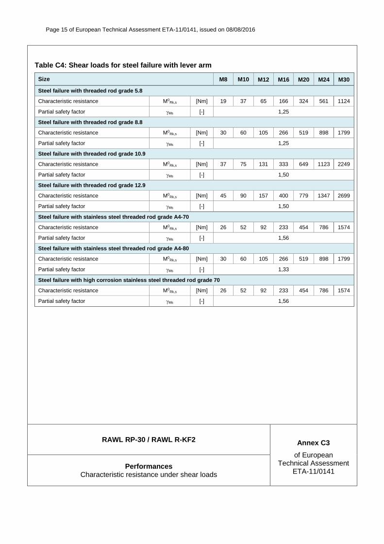
Page 15 of European Technical Assessment ETA-11/0141, issued on 08/08/2016
RAWL RP-30 / RAWL R-KF2 Annex C3
of European Technical Assessment
ETA-11/0141 Performances
Characteristic resistance under shear loads
Table C4: Shear loads for steel failure with lever arm
Size M8 M10 M12 M16 M20 M24 M30
Steel failure with threaded rod grade 5.8
Characteristic resistance M0Rk,s [Nm] 19 37 65 166 324 561 1124
Partial safety factor Ms [-] 1,25
Steel failure with threaded rod grade 8.8
Characteristic resistance M0Rk,s [Nm] 30 60 105 266 519 898 1799
Partial safety factor Ms [-] 1,25
Steel failure with threaded rod grade 10.9
Characteristic resistance M0Rk,s [Nm] 37 75 131 333 649 1123 2249
Partial safety factor Ms [-] 1,50
Steel failure with threaded rod grade 12.9
Characteristic resistance M0Rk,s [Nm] 45 90 157 400 779 1347 2699
Partial safety factor Ms [-] 1,50
Steel failure with stainless steel threaded rod grade A4-70
Characteristic resistance M0Rk,s [Nm] 26 52 92 233 454 786 1574
Partial safety factor Ms [-] 1,56
Steel failure with stainless steel threaded rod grade A4-80
Characteristic resistance M0Rk,s [Nm] 30 60 105 266 519 898 1799
Partial safety factor Ms [-] 1,33
Steel failure with high corrosion stainless steel threaded rod grade 70
Characteristic resistance M0Rk,s [Nm] 26 52 92 233 454 786 1574
Partial safety factor Ms [-] 1,56

Page 16 of European Technical Assessment ETA-11/0141, issued on 08/08/2016
RAWL RP-30 / RAWL R-KF2 Annex C4
of European Technical Assessment
ETA-11/0141
Performances Characteristic resistance under shear loads.
Displacement under service loads: tension and shear loads
Table C4: Characteristic values for shear loads – pry out and concrete edge failure
Size M8 M10 M12 M16 M20 M24 M30
Effective anchorage depth hef min [mm] 60 70 80 100 120 140 165
max [mm] 100 120 145 190 240 290 360
Pry out failure
Factor acc. to equation (5.7) of TR 029 or acc. to equation (27) of CEN/TS 1992-4:2009
k1) = k3 2) [-] 2 2 2 2 2 2 2
Partial safety factor 3) Mp [-] 1,5
Concrete edge failure: see clause 5.2.3.4 of Technical Report TR 029
Partial safety factor 3) Mc [-] 1,5 1) factor according to EOTA Technical Report TR 029
2) factor according to CEN/TS 1992-4:2009 3) in the absence of national regulation
Table C5: Displacement under tension loads – non-cracked concrete
Size M8 M10 M12 M16 M20 M24 M30
Characteristic displacement in non-cracked concrete C20/25 to C50/60 under tension loads
Admissible service load 1) F [kN] 7,2 11,1 13,9 22,7 31,6 31,2 33,9
Displacement N0 [mm] 0,20 0,20 0,25 0,25 0,35 0,40 0,40
N [mm] 0,80 0,80 0,80 0,80 0,80 0,80 0,80
F = FRk / F ∙ Mc, with F = 1,4
These values are suitable for each temperature range and categories specified in Annex B1
Table C6: Displacement under shear loads
Size M8 M10 M12 M16 M20 M24 M30
Characteristic displacement under shear loads
Admissible service load 1) F [kN] 3,7 5,8 8,4 15,7 24,5 35,3 55,6
Displacement V0 [mm] 2,5 2,5 2,5 2,5 2,5 2,5 2,5
V [mm] 3,7 3,7 3,7 3,7 3,7 3,7 3,7
1) F = FRk / F ∙ Mc, with F = 1,4
These values are suitable for each temperature range and categories specified in Annex B1