european technical approval eta-13/0416 - strong-tie · european technical approval eta-13/0416...
TRANSCRIPT

Evropska organizacija za tehnična soglasja
European Organisation for Technical Approvals
Zavod za gradbeništvo Slovenije
Slovenian National Building and Civil Engineering Institute
Dimičeva 12,
1000 Ljubljana, Slovenija
Tel.: +386 (0)1-280 44 72, 280 45 37 Fax: +386 (0)1-436 74 49 e-mail: [email protected]
http://www.zag.si/ts
Ermächtigtu n d n o t i f i z i e r t
gemäß Artikel 10 derRichtlinie des Rates vom
21. Dezember 1988 zur An-gleichung der Rechts- undVerwaltungsvorschriften
der Mitg l ieds taatenüber Bauprodukte
(89/106/EWG)
član EOTA
European Technical Approval ETA-13/0416 [English translation prepared by ZAG – Original version in Slovenian language]
Komercialno ime Trade name
AT-HP masonry
Imetnik soglasja Holder of approval
SIMPSON STRONG-TIE EUROPE Z.A.C. des Quatre Chemiins 85400 Sainte Gemme La Plaine France
Tip gradbenega proizvoda in njegova predvidena uporaba Kovinsko kemično sidro za uporabo v zidakih
Generic type and use of construction product
Metal injection anchor for use in masonry
Veljavnost od Validity from
do to
24.06.2013 14.02.2018
Proizvodni obrat
Manufacturing plant
SIMPSON STRONG-TIE Zl Les Mourges 30350 CARDET
To Evropsko tehnično soglasje vsebuje
This European Technical Approval contains:
20 strani vključno s 12 prilogami, ki so sestavni del tega soglasja.
20 pages including 12 annexes which form an integral part of the document.

Page 2 of ETA-13/0416 issued on 24.06.2013, English translation prepared by ZAG
I LEGAL BASES AND GENERAL CONDITIONS
1. This European Technical Approval is issued by the Slovenian National Building and Civil Engineering Institute (ZAG) in accordance with:
Council Directive 89/106/EEC of 21 December 1988 on the approximation of laws, regulations and administrative provisions of Member States relating to construction products1, modified by the Council Directive 93/68/EEC2 and regulation (EC) No1882/2003 of the European Parliament and of the Council3,
Zakon o gradbenih proizvodih – ZGPro (Ur. List, št. 52/00 in 110/02) “Construction Product Act – ZGPro (OG RS No 52/00 and 110/02)”,
Common Procedural Rules for Requesting, Preparing and the Granting of European Technical Approvals set out in the Annex of Commission Decision 94/23/EC4,
Guideline for European Technical Approval of “"Metal Injection anchors for use in masonry”, ETAG 029, edition June 2010.
2. The Slovenian National Building and Civil Engineering Institute (ZAG) is authorised to check whether the provisions of this European Technical Approval are met. Checking may take place in the manufacturing plant. Nevertheless, the responsibility for the conformity of the products with the European Technical Approval and for their fitness for the intended use remains with the holder of the European Technical Approval.
3. This European Technical Approval is not to be transferred to manufacturers or agents of manufacturer other than those indicated on page 1; or manufacturing plants other than those indicated on page 1 of this European Technical Approval.
4. This European Technical Approval may be withdrawn by the Slovenian National Building and Civil Engineering Institute (ZAG), in particular pursuant to information by the Commission according to Article 5 (1) of the Council Directive 89/106/EEC.
5. Reproduction of this European Technical Approval including transmission by electronic means shall be in full. However, partial reproduction can be made with the written consent of the Slovenian National Building and Civil Engineering Institute (ZAG). In this case partial reproduction has to be designated as such. Texts and drawings of advertising brochures shall not contradict or misuse the European Technical Approval.
6. The European Technical Approval is issued by the approval body in its official language. This version corresponds fully to the version circulated within EOTA. Translations into other languages have to be designated as such.
1 Official Journal of the European Communities N
o L 40, 11.2.1989, p.12
2 Official Journal of the European Communities N
o L 220, 30.8.1993, p.1
3 Official Journal of the European Union N
o L 284, 31.10.2003, p.1
4 Official Journal of the European Communities N
o L 17, 20.1.1994, p.34

Page 3 of ETA-13/0416 issued on 24.06.2013, English translation prepared by ZAG
II SPECIFIC CONDITIONS OF THE EUROPEAN TECHNICAL APPROVAL
1 Definition of product and intended use
1.1 Definition of product
The injection system AT-HP masonry is bonded anchor (injection type) consisting of a mortar cartridge with injection mortar AT-HP a perforated plastic sleeve and an anchor rod (with hexagon nut and washer) of sizes M8, M10 and M12. The steel elements are made of zinc coated steel and stainless steel.
The anchor rod is placed into a drilled hole/perforated plastic sleeve filled with the injection mortar and anchored through the bond between element, injection mortar and masonry.
An illustration of the product and intended use is shown in Annexes 1 and 2.
1.2 Intended use
The anchor is intended to be used for anchorages for which requirements for safety in use in the sense of the Essential Requirement 1 and 4 of Council Directive 89/106/EEC shall be fulfilled and failure of anchorages made with these products would cause risk to human life and/or lead to considerable economic consequences.
The anchor is to be used only for anchorages subjected to static and quasi-static loading in solid masonry (category b), hollow or perforated masonry (category c) and autoclaved aerated concrete masonry (category d) according to Annex 8. The mortar strength class of the masonry has to be M 2,5 according to EN 998-2:2003 at minimum.
The anchor may be installed and used in dry or wet conditions (w/w), except in autoclaved aerated concrete where anchor can be installed and used only in dry conditions (d/d).
The anchor may be used in the service temperature range from -40°C to +80°C (maximum long term temperature +50°C and maximum short term temperature +80°C).
The elements made of galvanized steel may be only used in structured subjected to dry internal conditions.
The elements made of stainless steel may be used in structures subject to dry internal conditions and also in structures subject to external atmospheric exposure (including industrial and marine environment), or exposure in permanently damp internal conditions, if no particular aggressive conditions exist. Such particular aggressive conditions are e.g. permanent, alternating immersion in seawater or the splash zone of seawater, chloride atmosphere of indoor swimming pools or atmosphere with extreme chemical pollution (e.g. desulphurization plants or road tunnels where de-icing material are used).
The provisions made in this European Technical Approval are based on an assumed working life of the anchor of 50 years. The indications given on the working life cannot be interpreted as a guarantee given by the producer, but are to be regarded only as a means for choosing the right products in relation to the expected economically reasonable working life of the works

Page 4 of ETA-13/0416 issued on 24.06.2013, English translation prepared by ZAG
2 Characteristics of product and methods of verification
2.1 Characteristics of product
The anchor corresponds to the drawings and information given in Annexes 1 to 8. The characteristic material values, dimensions and tolerances of the anchor not indicated in these Annexes shall correspond to the respective values laid down in the technical documentation5 of this European Technical Approval.
The characteristic anchor values for the design of anchorage are given in Annexes 9 to 11
The metal part of the injection anchor are assumed to satisfy the requirements for class A1 of the characteristic reaction to fire.
Regarding resistance to fire no performance is determined.
2.2 Methods of verification
The assessment of fitness of the anchor for the intended use in relation to the requirements for mechanical resistance, stability and safety in use in the sense of the Essential Requirement 1 and 4 has been made in accordance with the “Guideline for European Technical Approval of Metal injection anchors for use in masonry”, ETAG 029, based on the use categories b, c and d in respect of the base material and category w/w in respect of installation and use (for clay bricks-category b and c) and category d/d (for autoclaved aerated concrete-category d) in respect of the installation and use.
In addition to the specific clauses relating to dangerous substances contained in this European Technical Approval, there may be other requirements applicable to the products falling within its scope (e. g. transposed European legislation and national laws, regulations and administrative provisions). In order to meet the provisions of the Construction Products Directive, these requirements need also to be complied with, when and where they apply.
3 Evaluation and attestation of conformity and CE marking
3.1 System of attestation of conformity
According to the decision 97/177/EC of the European Commission6 the system 1 of attestation of conformity applies.
This system of attestation of conformity is defined as follows:
System 1: Certification of the conformity of the product by an approved certification body on the basis of:
a) tasks for the manufacturer:
(1) factory production control;
(2) further testing of samples taken at the factory by the manufacturer in accordance with a control plan.
b) tasks for the approved body:
(3) initial type-testing of the product;
(4) initial inspection of factory and of factory production control;
(5) continuous surveillance, assessment and approval of factory production control.
5 The technical documentation of this European Technical Approval is deposited at the Slovenian National
Building and Civil Engineering Institute (ZAG) and, as far as relevant for the tasks of the approved bodies involved in the attestation of conformity procedure, is handed over the approved bodies.
6 Official Journal of the European Communities L 198/31 of 25.7.1997
Page 5 of ETA-13/0416 issued on 24.06.2013, English translation prepared by ZAG
3.2 Responsibilities
3.2.1 Tasks of the manufacturer
3.2.1.1 Factory production control
The manufacturer shall exercise permanent internal control of production. All the elements, requirements and provisions adopted by the manufacturer are documented in a systematic manner in the form of written policies and procedures, including records of results performed. This production control system ensures that the product is in conformity with the European technical approval.
The manufacturer shall only use raw materials stated in the technical documentation of this European technical approval.
The factory production control shall be in accordance with the “Control Plan” relating to the European technical approval ETA–13/0416 issued on 24.06.2013, which is part of the technical documentation of this European technical approval. The “Control Plan” is laid down in the context of the factory production control system operated by the manufacturer and deposited at the Slovenian National Building and Civil Engineering Institute (ZAG).
The results of factory production control shall be recorded and evaluated in accordance with the provisions of the “Control Plan”.
3.2.1.2 Other tasks of the manufacturer
The manufacturer shall, on the basis of a contract, involve a body which is approved for the tasks referred to in a section 3.1 in the field of anchors in order to undertake the actions laid down in section 3.2.2. For this purpose the “Control Plan” referred to in sections 3.2.1.1 and 3.2.2 shall be handed over by the manufacturer to the approved body or bodies involved.
The manufacturer shall make a declaration of conformity, stating that the construction product is in conformity with the provisions of the European technical approval ETA–13/0416 issued on 24.06.2013.
3.2.2 Tasks of approved bodies
The notified body shall perform the:
- initial type testing of the product,
- initial inspection of factory and of factory production control,
- continuous surveillance, assessment and approval of factory production control.
in accordance with the provisions laid down in the “Control plan” which is the part of technical documentation of this European technical approval.
The notified body shall retain the essential points of its actions referred to above and state the results obtained and conclusions drawn in a written report.
The notified certification body involved by the manufacturer shall issue an EC certificate of conformity control stating the conformity with the provisions of this European technical approval.
In cases where the provisions of the European technical approval and its “Control Plan” are no longer fulfilled the certification body shall withdraw the certificate of conformity and inform the Slovenian National Building and Civil Engineering Institute (ZAG) without delay.

Page 6 of ETA-13/0416 issued on 24.06.2013, English translation prepared by ZAG
3.3 CE-Marking
The CE marking shall be affixed on each packaging of anchors. The symbol “CE” shall be followed by the identification number of the approved certification body and be accompanied by the following additional information:
the name and address of the manufacturer
the last two digits of the year in which the CE-marking was affixed,
the number of the EC certificate for the factory production control,
the number of the European technical approval,
the number of the guideline for European technical approval (ETAG 029),
use category (b, c and w/w or d and d/d),
size.
4 Assumptions under which the fitness of the product for the intended use was favourably assessed
4.1 Manufacturing
The European technical approval is issued for the product on the basis of agreed data/information, deposited with the Slovenian National Building and Civil Engineering Institute (ZAG), which identifies the product that has been assessed and judged. Changes to the product or production process, which could result in this deposited data/information being incorrect, should be notified to the Slovenian National Building and Civil Engineering Institute (ZAG) before the changes are introduced. The Slovenian National Building and Civil Engineering Institute (ZAG) will decide whether or not such changes affect the ETA and consequently the validity of the CE marking on the basis of the ETA and if so whether further assessment or alternations to the ETA, shall be necessary.
4.2 Installation
4.2.1 Design of anchorages
The fitness of the anchors for the intended use is given under the following conditions:
The anchorages are designed in accordance with the ETAG 029 “Guideline for European Technical Approval of Metal injection anchors for use in masonry”, Design Method A under the responsibility of an engineer experienced in anchorages and masonry work.
Verifiable calculation notes and drawings are prepared taking account the relevant masonry in the region of the anchorage (nature and strength of the base materials), the loads to be transmitted and their transmission to the supports of the structure. The position of the anchor is indicated on the design drawings (e.g. position of the anchor relative to the supports etc.).
The characteristic resistance for use in solid masonry are only valid for the base material and the bricks according to Annex 8 or larger brick sizes and larger compressive strength of the masonry unit.
The characteristic resistances for use in hollow or perforated masonry are only valid for the use of the bricks and blocks according to Annex 8 regarding base material, size of the units, compressive strength and configuration of the voids.
The characteristic resistance for use in autoclaved aerated concrete are only valid for the base material and the blocks according to Annex 8 or larger blocks sizes and larger compressive strength of the material.
For smaller brick or blocks sizes and smaller compressive strength in solid masonry and autoclaved aerated concrete or different bricks and blocks in hollow or perforated masonry on the construction site, the characteristic resistance of the anchor may be determined by job site tests according to ETAG 029 “Metal injections anchors for use in masonry, Annex B. Recommendations
Page 7 of ETA-13/0416 issued on 24.06.2013, English translation prepared by ZAG
for tests to be carried out on construction works” under the consideration of the -factor according to Annex 10, Table 13.
4.2.2 Installation of anchor
The fitness for use of the anchor can only be assumed if the following conditions of installation are met:
Anchor installation carried out by appropriately qualified personnel under the supervision of the person responsible for technical matters on site.
Use of the anchor only as supplied by the manufacturer without exchanging any component of the anchor.
Anchor installation in accordance with the manufacturer's specifications and drawings using tools indicated in this European Technical Approval.
Commercial standard threaded rods, washers and hexagon nuts may also be used if the following requirements are fulfilled:
Material, dimensions and mechanical properties of the metal parts according to the specification given in Annex 7, Tables 1 to 7,
Confirmation of material and mechanical properties of the metal parts by inspection certificate 3.1 according to EN 12024:2004, the documents should be stored,
Marking of the threaded rod with the envisage embedment depth. This may be done by the manufacturer of the rod or the person on jobsite.
Checks before placing the anchor, to ensure that the characteristic values of the base material in which the anchor is to be placed, is identical with the values, which the characteristic loads apply for.
Holes to be drilled perpendicular to the surface of the base material.
In case of aborted hole the drill hole should be filled with mortar.
Hole cleaning and anchor installation in accordance with the manufacturer’s installation instructions (Annexes 4 and 5).
Keeping the installation parameters (Annexes 6 and 7).
Marking and keeping the effective anchorage depth.
Keeping edge distance and spacing according to Annex 11 without minus tolerances.
Observation of the curing time according to Annex 7, Table 7 until the anchor may be loaded.
5 Indications to the manufacturer
5.1 Responsibility for the manufacturer
It is in the responsibility of the manufacturer to ensure that the information on the specific conditions according to 1 and 2 including Annexes referred to 4.2.1, 4.2.2 and 5.2 is given to those who are concerned. This information may be made by reproduction of the respective parts of the European Technical Approval. In addition, all installation data shall be shown clearly on the packaging and/or on an enclosed instruction sheet, preferably using illustration.
The minimum data required are:
Installation parameters according to Annexes 6 and 7, Tables 1 to 7
Material and property class of metal parts according to Annex 8, Table 8,
Information on the installation procedure, including cleaning of the hole with the cleaning equipment, preferably by means of an illustration,
Exact volume of injection mortar depend on the relevant installation,
Storage temperature of the anchor components, minimum and maximum temperature of the base material, processing time (open time) of the mortar and curing time until the anchor may be loaded according to Annex 7, Table 7,
Identification of the manufacturing batch.
Page 8 of ETA-13/0416 issued on 24.06.2013, English translation prepared by ZAG
All data shall be presented in a clear and explicit form.
5.1 Packing, transport and storage
The injection cartridges shall be protected against sun radiation and shall be stored according to manufacturer’s installation instructions in dry conditions at temperature of at least +5°C to not more than +30°C.
Mortar cartridges with expired shelf life must no longer be used.
Leading expert:
Dušica Drobnič, M.Sc., (Civ.eng.)
Head of the Service for Technical Approvals:
Franc Capuder, M.Sc., (Civ.eng.)

Page 9 of ETA-13/0416 issued on 24.06.2013, English translation prepared by ZAG
Anchor rods
Perforated plastic sleeve
Diameter of the sleeve: ds = 16 mm
Length of the sleeve: ls = 85 mm, 130 mm
AT-HP masonry Annex 1
of the European Technical Approval
ETA–13/0416 Components of the anchor
Page 10 of ETA-13/0416 issued on 24.06.2013, English translation prepared by ZAG
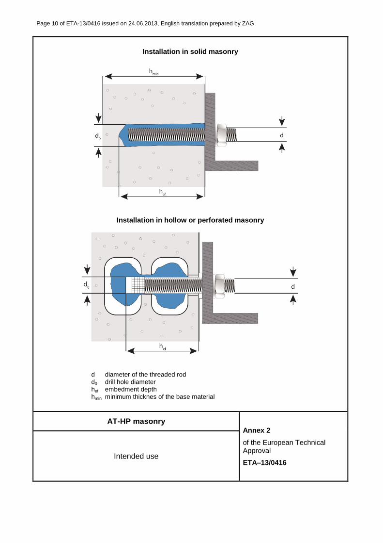
Installation in solid masonry
Installation in hollow or perforated masonry
d diameter of the threaded rod d0 drill hole diameter hef embedment depth hmin minimum thicknes of the base material
AT-HP masonry Annex 2
of the European Technical Approval
ETA–13/0416 Intended use

Page 11 of ETA-13/0416 issued on 24.06.2013, English translation prepared by ZAG
Mortar cartridges, applicator guns and mixing nozzles
cartridge Applicator gun Mixing nozzle
Coaxial cartridge:
160 ml
Coaxial cartridge:
280 ml
Sausage cartridge:
300 ml
Side by side cartridge:
345 ml
Coaxial cartridge:
380 ml
Side by side cartridge:
825 ml
AT-HP masonry
Annex 3
of the European Technical Approval
ETA–13/0416 Mortar cartridges, applicator guns and mixing nozzles

Page 12 of ETA-13/0416 issued on 24.06.2013, English translation prepared by ZAG
Installation procedure for solid masonry
1 Drill a hole to the correct diameter and depth using percussive machine.
2 The hole shall be cleaned by at least 2 blowing operations, 2 brushing operations followed again by 2 blowing operations.
3 Remove the cap an install mixing nozzle.
4 Load the cartridge into applicator gun.
5 Disperse and discard first part of resin until it is properly mixed.
6 Place the mixer at the bottom in the hole and inject the resin so long until the hole is filled up to approximately 70%.
7 Insert the oil-free threaded rod by slight turning right and left until the bottom of the hole. Clean excess resin.
8 Leave the fixing until minimum curing time has elapsed. Then attach the fixture and tighten the nut.
AT-HP masonry Annex 4
of the European Technical Approval
ETA–13/0416
Installation procedure for solid masonry and autoclaved aerated concrete

Page 13 of ETA-13/0416 issued on 24.06.2013, English translation prepared by ZAG
Installation procedure for hollow/perforated masonry
1 Drill a hole to the correct diameter and depth using a rotary machine.
2 The hole shall be cleaned by at least 2 brushing operations.
3 Insert the sleeve into the hole.
3 Remove the cap an install mixing nozzle.
4 Load the cartridge into applicator gun.
5 Disperse and discard first part of resin until it is properly mixed.
6 Place the mixer at the bottom in the hole and inject the resin so long until the hole is filled up to approximately 100%.
7 Insert the oil-free threaded rod by slight turning right and left until the bottom of the hole. Clean excess resin.
8 Leave the fixing until minimum curing time has elapsed. Then attach the fixture and tighten the nut.
AT-HP masonry Annex 5
of the European Technical Approval
ETA–13/0416 Installation procedure for hollow/perforated masonry
Page 14 of ETA-13/0416 issued on 24.06.2013, English translation prepared by ZAG
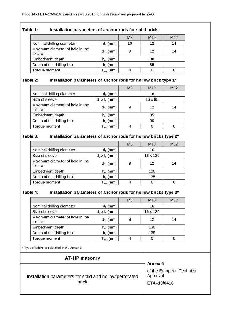
Table 1: Installation parameters of anchor rods for solid brick
M8 M10 M12
Nominal drilling diameter d0 (mm) 10 12 14
Maximum diameter of hole in the fixture
dfix (mm) 9 12 14
Embedment depth hef (mm) 80
Depth of the drilling hole h1 (mm) 85
Torque moment Tinst (nm) 4 6 8
Table 2: Installation parameters of anchor rods for hollow brick type 1*
M8 M10 M12
Nominal drilling diameter d0 (mm) 16
Size of sleeve ds x ls (mm) 16 x 85
Maximum diameter of hole in the fixture
dfix (mm) 9 12 14
Embedment depth hef (mm) 85
Depth of the drilling hole h1 (mm) 90
Torque moment Tinst (nm) 4 6 6
Table 3: Installation parameters of anchor rods for hollow bricks type 2*
M8 M10 M12
Nominal drilling diameter d0 (mm) 16
Size of sleeve ds x ls (mm) 16 x 130
Maximum diameter of hole in the fixture
dfix (mm) 9 12 14
Embedment depth hef (mm) 130
Depth of the drilling hole h1 (mm) 135
Torque moment Tinst (nm) 4 6 6
Table 4: Installation parameters of anchor rods for hollow bricks type 3*
M8 M10 M12
Nominal drilling diameter d0 (mm) 16
Size of sleeve ds x ls (mm) 16 x 130
Maximum diameter of hole in the fixture
dfix (mm) 9 12 14
Embedment depth hef (mm) 130
Depth of the drilling hole h1 (mm) 135
Torque moment Tinst (nm) 4 6 8
* Type of bricks are detailed in the Annex 8
AT-HP masonry Annex 6
of the European Technical Approval
ETA–13/0416
Installation parameters for solid and hollow/perforated brick
Page 15 of ETA-13/0416 issued on 24.06.2013, English translation prepared by ZAG
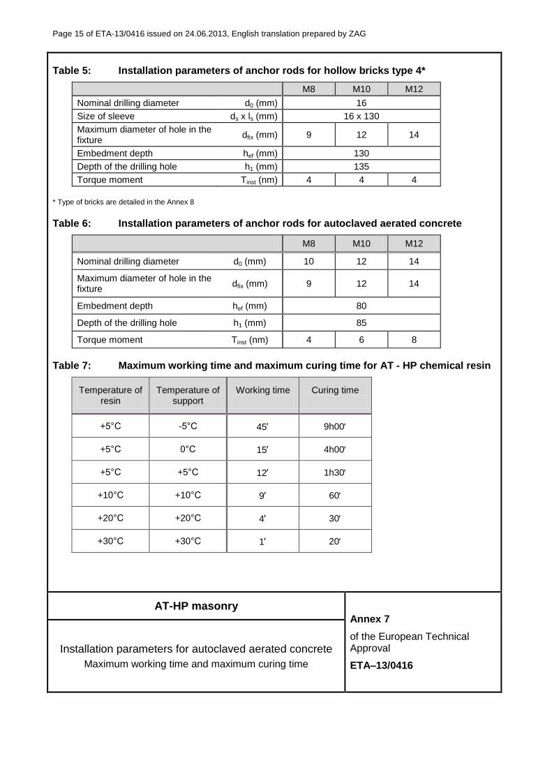
Table 5: Installation parameters of anchor rods for hollow bricks type 4*
M8 M10 M12
Nominal drilling diameter d0 (mm) 16
Size of sleeve ds x ls (mm) 16 x 130
Maximum diameter of hole in the fixture
dfix (mm) 9 12 14
Embedment depth hef (mm) 130
Depth of the drilling hole h1 (mm) 135
Torque moment Tinst (nm) 4 4 4
* Type of bricks are detailed in the Annex 8
Table 6: Installation parameters of anchor rods for autoclaved aerated concrete
M8 M10 M12
Nominal drilling diameter d0 (mm) 10 12 14
Maximum diameter of hole in the fixture
dfix (mm) 9 12 14
Embedment depth hef (mm) 80
Depth of the drilling hole h1 (mm) 85
Torque moment Tinst (nm) 4 6 8
Table 7: Maximum working time and maximum curing time for AT - HP chemical resin
Temperature of resin
Temperature of support
Working time
Curing time
+5°C -5°C 45 9h00
+5°C 0°C 15 4h00
+5°C +5°C 12 1h30
+10°C +10°C 9 60
+20°C +20°C 4 30
+30°C +30°C 1 20
AT-HP masonry Annex 7
of the European Technical Approval
ETA–13/0416
Installation parameters for autoclaved aerated concrete
Maximum working time and maximum curing time

Page 16 of ETA-13/0416 issued on 24.06.2013, English translation prepared by ZAG
Table 7: Materials
Part Material
1 Chemical mortar AT-HP
Methacrylate, grey and beige
2 Perforated sleeve
Polypropylene
3 Threaded rod
Zinc plated steel ≥ 5 m according to EN ISO 4042 (A2)
Hot-dip galvanized steel ≥ 40 m according to EN ISO 10684 Carbon steel property class 5.8 or 8.8 acc. to EN ISO 898-1
Stainless steel Stainless steel: 1.4362, 1.4401, 1.4404, 1.4439, 1.4571, 1.4578 according to EN 10088, property class 70 according to EN ISO 3506-1
Stainless steel – High corrosion resistance steel Stainless steel: 1.4529, 1.4565 according to EN 10088, property class 70 according to EN ISO 3506-1
Commercial threaded rods with Inspection certificate 3.1 according to EN 10204:2004 and marking of embedment depth (this may be done by the manufacturer of the rod or by the worker in jobsite)
4 Hexagon nut
Zinc plated steel ≥ 5 m according to EN ISO 4042 (A2)
Hot-dip galvanized steel ≥ 40 m according to EN ISO 10684 According to DIN 934 (EN ISO 4032), property class 8 according to EN ISO 898-2
Stainless steel According to DIN 934 (EN ISO 4032), property class 70 according to EN ISO 3506-2, Stainless steel: 1.4362, 1.4401, 1.4404, 1.4439, 1.4571, 1.4578 according to EN 10088
Stainless steel – High corrosion resistance steel According to DIN 934 (EN ISO 4032), property class 70 according to EN ISO 3506-2, Stainless steel: 1.4529, 1.4565 according to EN 10088
5 Washer
Zinc plated steel ≥ 5 m according to EN ISO 4042 (A2)
Hot-dip galvanized steel ≥ 40 m according to EN ISO 10684 According to DIN 125 (EN ISO 7089), DIN 440 (EN ISO 7094), DIN 9021 (EN ISO 7093)
Stainless steel According to DIN 125 (EN ISO 7089), DIN 440 (EN ISO 7094), DIN 9021 (EN ISO 7093 Stainless steel: 1.4362, 1.4401, 1.4404, 1.4439, 1.4571, 1.4578 according to EN 10088
Stainless steel – High corrosion resistance steel According to DIN 125 (EN ISO 7089), DIN 440 (EN ISO 7094), DIN 9021 (EN ISO 7093), Stainless steel: 1.4529, 1.4565 according to EN 10088
AT-HP masonry Annex 8
of the European Technical Approval
ETA–13/0416 Materials
Page 17 of ETA-13/0416 issued on 24.06.2013, English translation prepared by ZAG
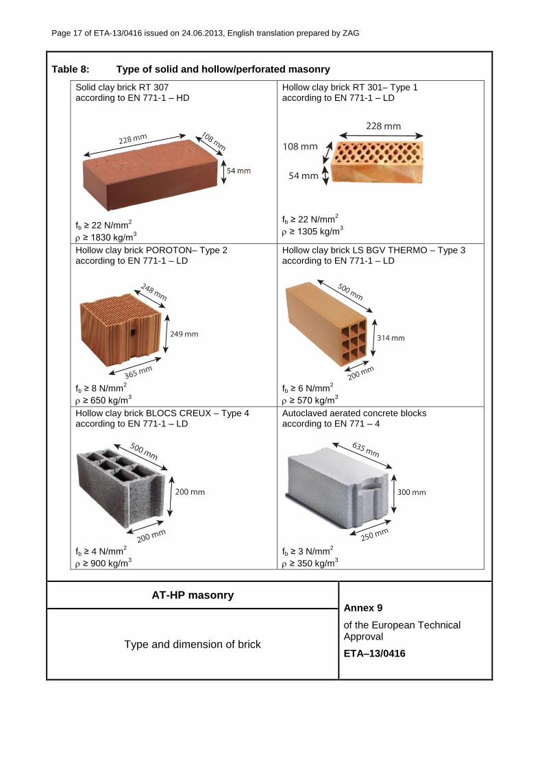
Table 8: Type of solid and hollow/perforated masonry
Solid clay brick RT 307 according to EN 771-1 – HD
fb ≥ 22 N/mm
2
≥ 1830 kg/m3
Hollow clay brick RT 301– Type 1 according to EN 771-1 – LD
fb ≥ 22 N/mm2
≥ 1305 kg/m3
Hollow clay brick POROTON– Type 2 according to EN 771-1 – LD
fb ≥ 8 N/mm
2
≥ 650 kg/m3
Hollow clay brick LS BGV THERMO – Type 3 according to EN 771-1 – LD
fb ≥ 6 N/mm
2
≥ 570 kg/m3
Hollow clay brick BLOCS CREUX – Type 4 according to EN 771-1 – LD
fb ≥ 4 N/mm
2
≥ 900 kg/m3
Autoclaved aerated concrete blocks according to EN 771 – 4
fb ≥ 3 N/mm
2
≥ 350 kg/m3
AT-HP masonry Annex 9
of the European Technical Approval
ETA–13/0416 Type and dimension of brick
Page 18 of ETA-13/0416 issued on 24.06.2013, English translation prepared by ZAG
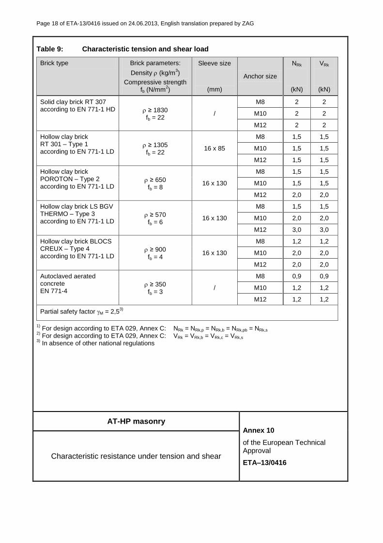
Table 9: Characteristic tension and shear load
Brick type Brick parameters:
Density (kg/m3)
Compressive strength fb (N/mm
2)
Sleeve size
(mm)
Anchor size
NRk
(kN)
VRk
(kN)
Solid clay brick RT 307 according to EN 771-1 HD ≥ 1830
fb = 22 /
M8 2 2
M10 2 2
M12 2 2
Hollow clay brick RT 301 – Type 1 according to EN 771-1 LD
≥ 1305 fb = 22
16 x 85
M8 1,5 1,5
M10 1,5 1,5
M12 1,5 1,5
Hollow clay brick POROTON – Type 2 according to EN 771-1 LD
≥ 650 fb = 8
16 x 130
M8 1,5 1,5
M10 1,5 1,5
M12 2,0 2,0
Hollow clay brick LS BGV THERMO – Type 3 according to EN 771-1 LD
≥ 570 fb = 6
16 x 130
M8 1,5 1,5
M10 2,0 2,0
M12 3,0 3,0
Hollow clay brick BLOCS CREUX – Type 4 according to EN 771-1 LD
≥ 900 fb = 4
16 x 130
M8 1,2 1,2
M10 2,0 2,0
M12 2,0 2,0
Autoclaved aerated concrete EN 771-4
≥ 350 fb = 3
/
M8 0,9 0,9
M10 1,2 1,2
M12 1,2 1,2
Partial safety factor M = 2,53)
1) For design according to ETA 029, Annex C: NRk = NRk,p = NRk,b = NRk,pb = NRk,s
2) For design according to ETA 029, Annex C: VRk = VRk,b = VRk,c = VRk,s
3) In absence of other national regulations
AT-HP masonry Annex 10
of the European Technical Approval
ETA–13/0416 Characteristic resistance under tension and shear

Page 19 of ETA-13/0416 issued on 24.06.2013, English translation prepared by ZAG
Table 10: Characteristic bending moments
Size M8 M10 M12
Characteristic bending moment for threaded steel rod grade 5.8
MRk,s (Nm) 20 39 68
Partial safety factor Ms / 1,25
Characteristic bending moment for threaded steel rod grade 8.8
MRk,s (Nm) 30 60 105
Partial safety factor Ms / 1,25
Characteristic bending moment for threaded stainless rod A4-70
MRk,s (Nm) 26 52 92
Partial safety factor Ms / 1,56
Table 11: Displacement under tension and shear load
F (kN)
N0
(mm) N∞
(mm) V0
(mm) V∞
(mm)
Solid brick
NRk / (1.4 M)
0,56 1,12 0,87 1,25
Hollow/perforated brick 0,81 1,62 1,20 1,80
Autoclaved aerated concrete 0,57 0,60 0,97 1,45
Table 12: -factors for job site tests according to ETAG 029 – Annex B
Brick type -factor
Solid and hollow/perforated brick
EN 771-1 0,86
Autoclaved aerated concrete EN 771-4
0,76
AT-HP masonry Annex 11
of the European Technical Approval
ETA–13/0416
Characteristic bending moments
Displacements
-factors for job site tests

Page 20 of ETA-13/0416 issued on 24.06.2013, English translation prepared by ZAG
Table 13: Edge distances and spacings
scr ccr smin cmin
(mm) (mm) (mm) (mm)
Solid brick 20 x d 10 x d 50 50
Hollow/perforated brick lunit 0.5 x lunit 100 100
Autoclaved aerated concrete 20 x d 10 x d 50 50
d nominal diameter of threaded rod lunit maximum dimension of masonry unit h thickness of masonry
AT-HP masonry Annex 12
of the European Technical Approval
ETA–13/0416 Edge distances and spacing