european technical approval eta-10/0413 pitzl pb.pdf · page 3 of 55 of european technical approval...
TRANSCRIPT
ETA-Danmark A/S Kollegievej 6 DK-2920 Charlottenlund Tel. +45 72 24 59 00 Fax +45 72 24 59 04 Internet www.etadanmark.dk
MEMBER OF EOTA
Authorised and notified according to Article 10 of the Council Directive 89/106/EEC of 21 December 1988 on the approximation of laws, regulations and administrative provisions of Member States relating to construction products
European Technical Approval ETA-10/0413
Trade name: Pitzl GmbH & Co. KG post bases type 1001.00,
1003.00, 1005.00, 1007.00, 1008.00 8 to, 1014.00, 1015.00, 1016.00, 1016.30, 10920.00+A-D, 10920.30, 10921.00+A-D, 10921.10, 10921.30, 10921.30 6to, 10952.00 V2A, 10950.00, 10950.10, 10950.20, 10950.50, 10950.60, 10950.70, 10935.50, 10945.50, 10931.00 +A-C, 10931.10, 10931.30, 10931.30 6to, 10933.00, 10933.10, 10933.20, 10933.50, 10933.60, 10933.70, 10935.00, 10945.00, 10934.00 and 10934.30
Holder of approval: Pitzl GmbH & Co. KG Siemensstraße 26 DE-84051 Altheim Tel.: +49 08703 9346-0 Telefax: +49 08703 9346-55 Internet: www.pitzl.de
Generic type and use of con-struction product:
Three-dimensional nailing plate (Post bases for the support of timber columns and posts as load-bearing elements)
Valid from: to:
2010-11-26 2015-11-26
Manufacturing plant: Pitzl GmbH & Co. KG Siemensstraße 26 DE-84051 Altheim
This European Technical Approval contains:
55 pages including 2 annexes which form an integral part of the document
Page 2 of 55 of European Technical Approval no. ETA-10/0413
I LEGAL BASIS AND GENERAL CONDITIONS
1 This European Technical Approval is issued by
ETA-Danmark A/S in accordance with: - Council Directive 89/106/EEC of 21 December
1988 on the approximation of laws, regulations and administrative provisions of Member States relating to construction products1), as amended by Council Directive 93/68/EEC of 22 July 19932).
- Bekendtgørelse 559 af 27-06-1994 (afløser
bekendtgørelse 480 af 25-06-1991) om ikrafttræ-den af EF direktiv af 21. december 1988 om indbyrdes tilnærmelse af medlemsstaternes love og administrative bestemmelser om byggevarer.
- Common Procedural Rules for Requesting,
Preparing and the Granting of European Techni-cal Approvals set out in the Annex to Commis-sion Decision 94/23/EC3).
- EOTA Guideline ETAG 015 Three-dimensional
nailing plates, September 2002 edition. 2 ETA-Danmark A/S is authorized to check whet-
her the provisions of this European Technical Approval are met. Checking may take place in the manufacturing plant. Nevertheless, the responsi-bility for the conformity of the products to the European Technical Approval and for their fitness for the intended use remains with the holder of the European Technical Approval.
3 This European Technical Approval is not to be
transferred to manufacturers or agents of manu-facturers other than those indicated on page 1, or manufacturing plants other than those indicated on page 1 of this European Technical Approval.
4 This European Technical Approval may be
withdrawn by ETA-Danmark A/S pursuant to Article 5(1) of Council Directive89/106/EEC.
5 Reproduction of this European Technical Approval including transmission by electronic means shall be in full. However, partial reproduction can be made with the written consent of ETA-Danmark A/S. In this case partial reproduction has to be designated as such. Texts and drawings of advertising brochures shall not contradict or misuse the European Technical Approval.
6 This European Technical Approval is issued by ETA-
Danmark A/S in English. This version corresponds fully to the version circula-
ted within EOTA. Translations into other languages have to be designated as such.
1) Official Journal of the European Communities No L40, 11 Feb 1989, p 12. 2) Official Journal of the European Communities No L220, 30 Aug 1993, p 1. 3) Official Journal of the European Communities No L 17, 20 Jan 1994, p 34.
Page 3 of 55 of European Technical Approval no. ETA-10/0413
I SPECIAL CONDITIONS OF THE EUROPEAN TECHNICAL APPROVAL
1 Definition of product and intended use Definition of the product The Pitzl post bases are made of 5.0 mm to 15.0 mm thick steel plates. The post bases are produced of steel grade S235JR according to EN 10025-2:2005-04 with a minimum characteristic yield strength of ReH = 235 N/mm² and a minimum characteristic tensile strength of Rm = 360 N/mm² or of steel grade 1.4301 according to EN 10088-3:2005-09 with a minimum characteristic yield strength of Rp0,2 = 190 N/mm² and a minimum characteristic tensile strength of Rm = 500 N/mm². For the connections with metal fasteners dowels ø12 mm (S235) with minimum characteristic tensile strength of Rm = 360 N/mm² and screws 10x120 mm according to EN 14592 (DIN 571 and thread according to DIN 7998) with minimum characteristic tensile strength of Rm = 360 N/mm² are used. The screws shall be driven into pre-drilled holes according to EN 1995-1-1, 10.4.5. For anchorage in the foundation threaded rods or steel profiles are used. Dimensions are shown in Annex A and B. Intended use The intended use of the post bases is the support of timber columns and posts as load-bearing elements, where requirements for mechanical resistance and stability and safety in use in the sense of the Essential Requirements 1 and 4 of Council Directive 89/106/EEC shall be fulfilled.
The static and kinematical behaviour of the timber members or the supports shall be as described in Annex B.
The timber posts may be of solid timber of strength class C24 or better according to EN 338:2003-09. Minimum dimensions for the post have to be considered (Annex A). The end grain of the timber post in general must be plane on the base plate of the post base.
The maximum distance between the foundation and the base plate of the post base shall in general be 200 mm. For post bases type 1015, 1016, 10920, 10921 and 10931 larger distances are allowed.
Annex B states the load-carrying capacities of the post bases for solid timber of strength class C24 according to EN 338:2003-09. The design of the connections shall be in accordance with Eurocode 3 and Eurocode 5 or a similar national code. The anchorage of the post base in the foundation and imperfections exceeding the assumptions in Eurocode 5, 5.4.4 are not part of this
ETA. The post bases are for use in timber structures subject to the service classes 1, 2 and 3 of Eurocode 5 and for connections subject to static or quasi-static loading. In service class 3 the corrosion protection is given by stainless steel or zinc coating ZiNip or hot-dip zinc coating Z350 according to EN 10147. The metal fasteners must also be of stainless steel or have a zinc coating for the intended use in service class 3 of EN 1995-1-1 (zinc coating Fe/Zn 25c according to EN ISO 2081). The galvanic zinc coating of the post bases is only suitable for service classes 1 and 2. Assumed working life The assumed intended working life of the post bases for the intended use is 50 years, provided that they are subject to appropriate use and maintenance. The information on the working life should not be regarded as a guarantee provided by the manufacturer or ETA Danmark. An “assumed intended working life” means that it is expected that, when this working life has elapsed, the real working life may be, in normal use conditions, considerably longer without major degradation affecting the essential requirements.

Page 4 of 55 of European Technical Approval no. ETA-10/0413
2 Characteristics of product and assessment
ETAG paragraph
Characteristic
Assessment of characteristic
2.1 Mechanical resistance and stability*)
6.1.1
Characteristic load-carrying capacity
See Annex B
6.1.2
Stiffness
No performance determined
6.1.3
Ductility in cyclic testing
No performance determined
2.2 Safety in case of fire
6.2.1
Reaction to fire
The post bases are made from steel classified as Euroclass A1 in accordance with EN 1350-1 and EC decision 96/603/EC, amended by EC Decision 2000/605/EC
2.3 Hygiene, health and the environment
6.3.1
Influence on air quality
No dangerous materials **)
2.4 Safety in use
Not relevant
2.5 Protection against noise
Not relevant
2.6 Energy economy and heat retention
Not relevant
2.7 Related aspects of serviceability
6.7.1
Durability
The post bases have been assessed as having satisfactory durability and serviceability when used in timber structures using the timber species described in Eurocode 5 and subject to the conditions defined by service class 1 and 2
6.7.2
Serviceability
6.7.3
Identification
See Annex A
*) See page 5 of this ETA **) In accordance with http://europa.eu.int-/comm/enterprise/construction/internal/dangsub/dangmain.htm In addition to the specific clauses relating to dangerous substances contained in this European Technical Approval, there may be other requirements applicable to the products falling within its scope (e.g. transposed European legislation and national laws, regulations and administrative provisions). In order to meet the provisions of the EU Construction Products Directive, these requirements need also to be complied with, when and where they apply.

Page 5 of 55 of European Technical Approval no. ETA-10/0413
Safety principles and partial factors The characteristic load-carrying capacities are based on the characteristic values of the connections with metal fasteners, the steel plates and the timber post .
In the case of timber failure or failure of the metal fasteners, the design values shall be calculated according to EN 1995-1-1 by dividing the characteristic values of the load-carrying capacities by different partial factors for the strength properties, and in addition multiplied with the coefficient kmod.
In the case of steel failure, the design value shall be calculated according to EN 1993-1-1 by reducing the characteristic values of the load-carrying capacity with different partial factors.
The design value of the load-carrying capacity is the smaller value of all load-carrying capacities:
mod Rk,H Rk,SRd
M,H Mi,S
k F FF min ;
⋅=
γ γ
Therefore, for timber failure or failure of the metal fasteners the load duration class and the service class are included. The different partial factors γM for steel, timber or foundation failure, respectively, are also correctly taken into account. 2.1 Mechanical resistance and stability See Annex B for the characteristic load-carrying capacity in the different directions F1 to F5 for solid timber of strength class C24 according to EN 338:2003-09. Using the load-carrying capacities of the post bases, the specifications in Annex A must be fulfilled. The end grain of the timber post must in general be plane on the base plate of the post base.
The characteristic capacities of the post bases are determined by a combination of calculation according to Eurocode 3 and Eurocode 5 and testing. They should be used for designs in accordance with Eurocode 3 and Eurocode 5 or a similar national code. The characteristic capacities of the connecting unit consisting of screws and threaded rods or tubes were determined by using test results of Karlsruhe Institute of Technology.
No performance has been determined in relation to ductility of a joint under cyclic testing. The contribution to the performance of structures in seismic zones, therefore, has not been assessed.
No performance has been determined in relation to the joint’s stiffness properties - to be used for the analysis of the serviceability limit state.
No performance has been determined in relation to the anchorage of the post bases in the foundation. It must be checked by the designer of the structure to ensure it is not
less than the post base capacity and, if necessary, the post base capacity reduced accordingly. Therefore the specifi-cations for the lever arms eF2/F3 (for load case F2 / F3) and eF4/F5 (for load case F4 / F5) in annex A have to be considered. The lever arm is the distance between the top edge of the foundation and the load. 2.7 Related aspects of serviceability 2.7.1 Corrosion protection in service class 1 and 2. In accordance with ETAG 015 the post bases are made from steel grade S235JR according to EN 10025-2:2005-04 with minimum characteristic yield strength of ReH = 235 N/mm² and a minimum characteristic tensile strength of Rm = 360 N/mm² 2.7.2 Corrosion protection in service class 3 In accordance with Eurocode 5 the post bases are made from steel grade 1.4301 according to EN 10088-3:2005-09 with a minimum characteristic yield strength of Rp0,2 = 190 N/mm² and a minimum characteristic tensile strength of Rm = 500 N/mm².

Page 6 of 55 of European Technical Approval no. ETA-10/0413
3 Attestation of Conformity and CE marking
3.1 Attestation of Conformity system The system of attestation of conformity is 2+
described in Council Directive 89/106/EEC (Construction Products Directive) Annex III.
a) Tasks for the manufacturer:
(1) Factory production control, (2) Initial type testing of the product,
b) Tasks for the notified body: (1) Initial inspection of the factory and the
factory production control, (2) Continuous surveillance 3.2 Responsibilities 3.2.1 Tasks of the manufacturer 3.2.1.1 Factory production control
The manufacturer has a factory production control system in the plant and exercises permanent internal control of production. All the elements, requirements and provisions adopted by the manufacturer are documented in a systematic manner in the form of written policies and procedures. This production control system ensures that the product is in conformity with the European Technical Approval. The manufacturer shall only use raw materials supplied with the relevant inspection documents as laid down in the control plan4. The incoming raw materials shall be subject to controls and tests by the manufacturer before acceptance. Check of materials, such as sheet metal, shall include control of the inspection documents presented by suppliers (comparison with nominal values) by verifying dimension and determining material properties, e.g. chemical composition, mechanical properties and zinc coating thickness. The manufactured components are checked visually and for dimensions. The control plan, which is part of the technical documentation of this European Technical Approval,
4 The control plan has been deposited at ETA-Danmark and is only made available to the approved bodies involved in the conformity attestation procedure.
includes details of the extent, nature and frequency of testing and controls to be performed within the factory production control and has been agreed between the approval holder and ETA Danmark. The results of factory production control are recorded and evaluated. The records include at least the following information: - Designation of the product, basic material and
components; - Type of control or testing; - Date of manufacture of the product and date of
testing of the product or basic material and components;
- Result of control and testing and, if appropriate, comparison with requirements;
- Signature of person responsible for factory production control.
The records shall be presented to ETA Danmark on request.
3.2.1.1 Initial type testing of the product
For initial type-testing the results of the tests performed as part of the assessment for the European Technical Approval shall be used unless there are changes in the production line or plant. In such cases the necessary initial type testing has to be agreed between ETA Danmark and the notified body.
3.2.2. Tasks of notified bodies 3.2.2.1 Initial inspection of the factory and the factory production control
The approved body should ascertain that, in accordance with the control plan, the factory, in particular the staff and equipment, and the factory production control, are suitable to ensure a continuous and orderly manufacturing of the brackets with the specifications given in part 2.
3.2.2.2 Continuous surveillance
The approved body shall visit the factory at least twice a year for routine inspections. It shall be verified that the system of factory production control and the specified manufacturing processes are maintained, taking account of the control plan.
The results of product certification and continuous surveillance shall be made available on demand by the certification body to ETA Danmark. Where the provisions of the European Technical Approval and the control plan are no longer fulfilled, the certificate
Page 7 of 55 of European Technical Approval no. ETA-10/0413
of conformity shall be withdrawn by the approved body.
3.3 CE marking The CE marking shall be affixed on each packaging of brackets. The initials "CE" shall be followed by the identification number of the notified body and shall be accompanied by the following information:
- Name or identifying mark of the manufacturer
- The last two digits of the year in which the marking was affixed
- Number of the European Technical Approval
- Name and size of product - Number of the ETA Guideline
(ETAG no. 015) - Number of the EC Certificate of
Conformity
Page 8 of 55 of European Technical Approval no. ETA-10/0413
4 Assumptions under which the fitness of the product for the intended use was favourably assessed 4.1 Manufacturing Pitzl post bases are manufactured in accordance with the provisions of this European Technical Approval using the manufacturing processes as identified in the inspection of the plant by the notified inspection body and laid down in the technical documentation. 4.2 Installation
The stated type of fasteners for each post base has to be applied in applicable holes in the post base. The installation instructions to be followed are: • The primary structural member – the post member
shown in typical installation page 14 or a beam member - to which the post bases are fixed shall be:
– Restrained against rotation – Capable to transfer the force to the post bases as
assumed. – Free from wane in areas in contact with the post
base. • The secondary structural member – the concrete
support - to which the post bases are fixed shall be: – Made from concrete of at least strength class
C15, unless otherwise is indicated in annex B of this ETA.
• To ensure sufficient capacity the designer has to take
into account splitting of the timber. • The timber member shall be free from wane. • There shall be no gap between the timber and the
horizontal contact area. • Otherwise the gap between the timber member and
the post base may not exceed 3 mm. • There are no specific requirements relating to
preparation of the timber members.
The calculations are based on not pre-drilled holes for nails and screws. However the holes for lag screws, dowels and bolts have to be pre-drilled. • The execution of the connection shall be in
accordance with the approval holder’s technical literature.
4.3 Maintenance and repair Maintenance is not required during the assumed intended working life. Should repair prove necessary, it is normal to replace the connector.
Thomas Bruun Manager, ETA-Danmark
Page 9 of 55 of European Technical Approval no. ETA-10/0413
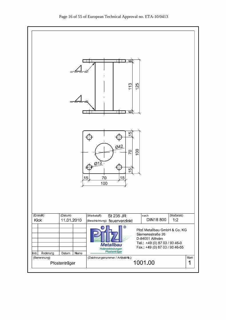
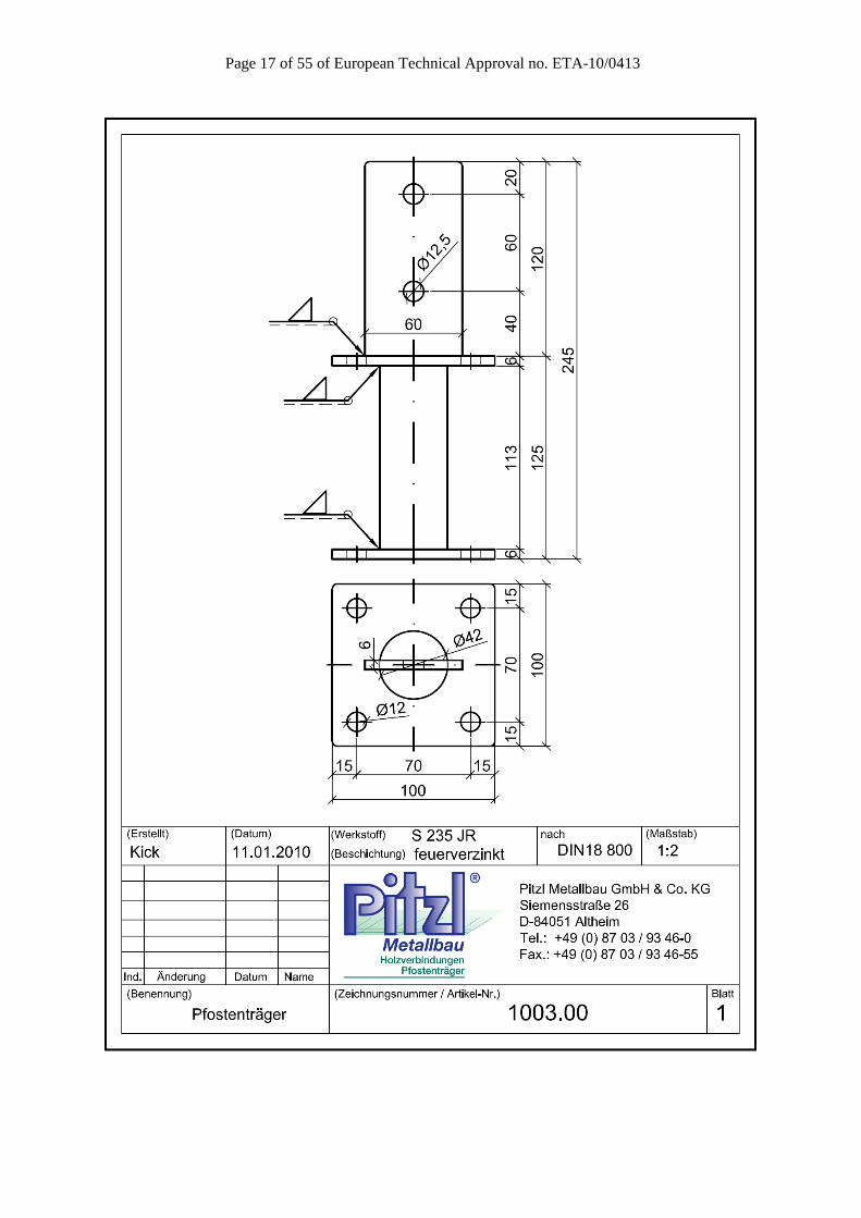
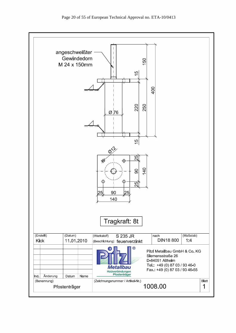
Annex A Product details and definitions
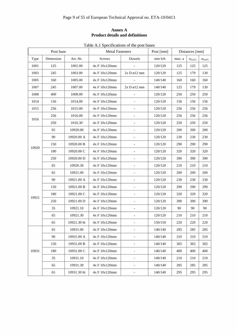
Table A.1 Specifications of the post bases
Post base Metal Fasteners Post [mm] Distances [mm]
Type Dimension Art.-Nr. Screws Dowels min b/h max. a eF2/F3 eF4/F5
1001 125 1001.00 4x F 10x120mm - 120/120 125 125 125
1003 245 1003.00 4x F 10x120mm 2x D ø12 mm 120/120 125 179 130
1005 160 1005.00 4x F 10x120mm - 140/140 160 160 160
1007 245 1007.00 4x F 10x120mm 2x D ø12 mm 140/140 125 179 130
1008 400 1008.00 4x F 10x120mm - 120/120 250 250 250
1014 156 1014.00 4x F 10x120mm - 120/120 156 156 156
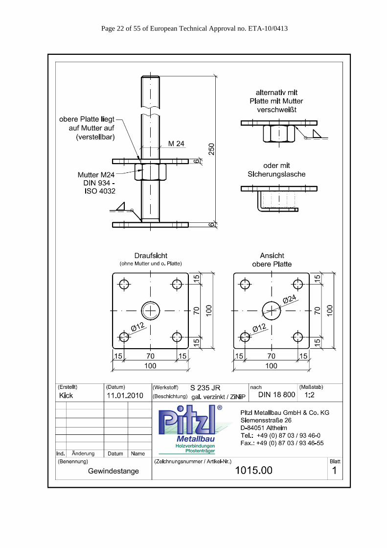
1015 256 1015.00 4x F 10x120mm - 120/120 256 256 256
1016 256 1016.00 4x F 10x120mm - 120/120 256 256 256
250 1016.30 4x F 10x120mm - 120/120 250 250 250
10920
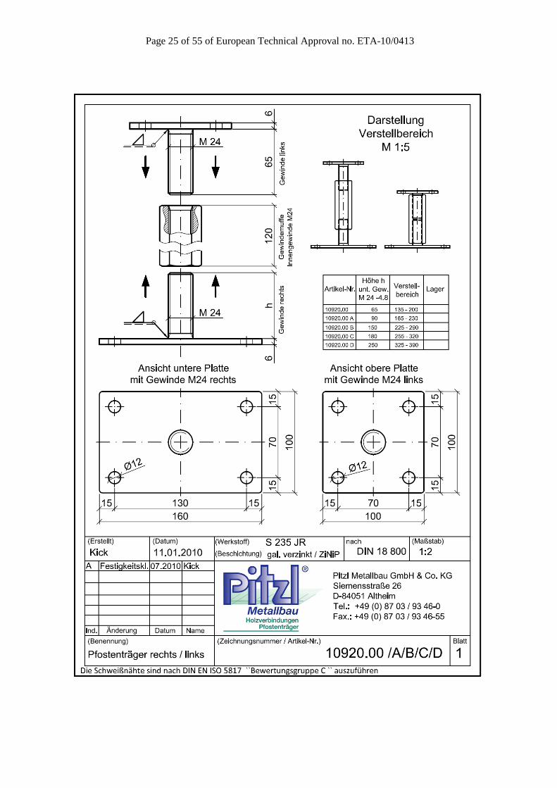
65 10920.00 4x F 10x120mm - 120/120 200 200 200
90 10920.00 A 4x F 10x120mm - 120/120 230 230 230
150 10920.00 B 4x F 10x120mm - 120/120 290 290 290
180 10920.00 C 4x F 10x120mm - 120/120 320 320 320
250 10920.00 D 4x F 10x120mm - 120/120 390 390 390
65 10920.30 4x F 10x120mm - 120/120 210 210 210
10921
65 10921.00 4x F 10x120mm - 120/120 200 200 200
90 10921.00 A 4x F 10x120mm - 120/120 230 230 230
150 10921.00 B 4x F 10x120mm - 120/120 290 290 290
180 10921.00 C 4x F 10x120mm - 120/120 320 320 320
250 10921.00 D 4x F 10x120mm - 120/120 390 390 390
35 10921.10 4x F 10x120mm - 120/120 90 90 90
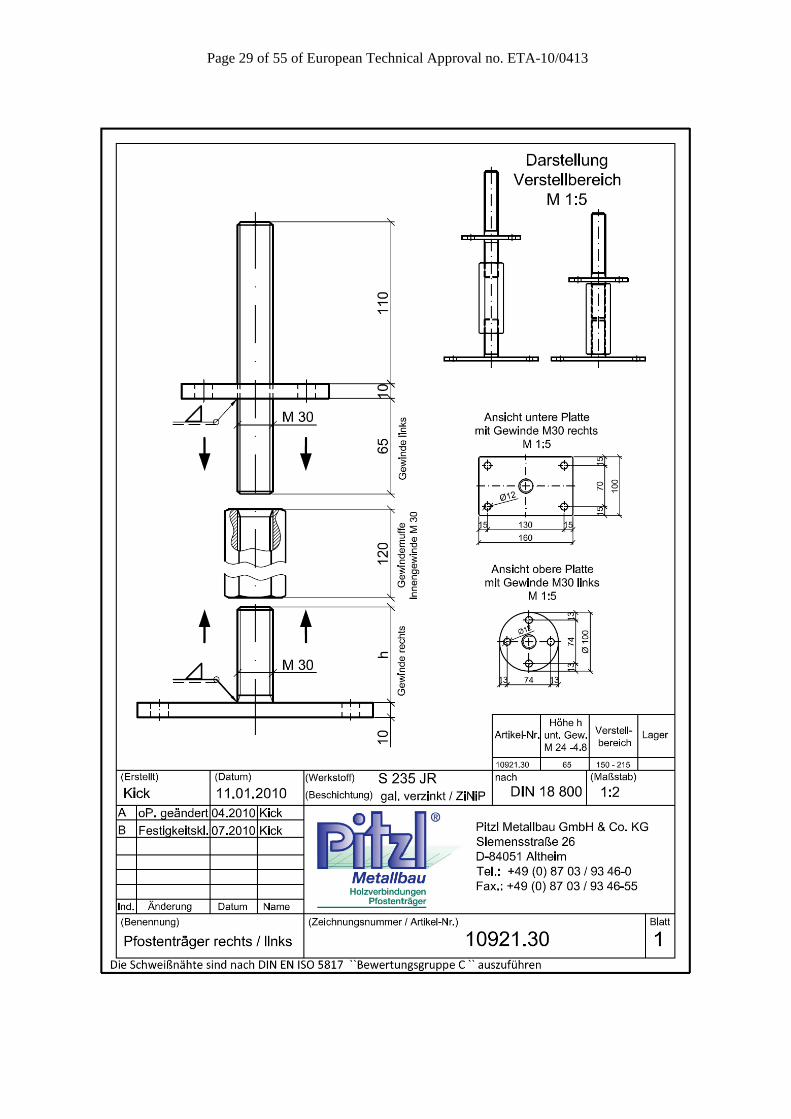
65 10921.30 4x F 10x120mm - 120/120 210 210 210
65 10921.30 6t 4x F 10x120mm - 150/150 220 220 220
10931
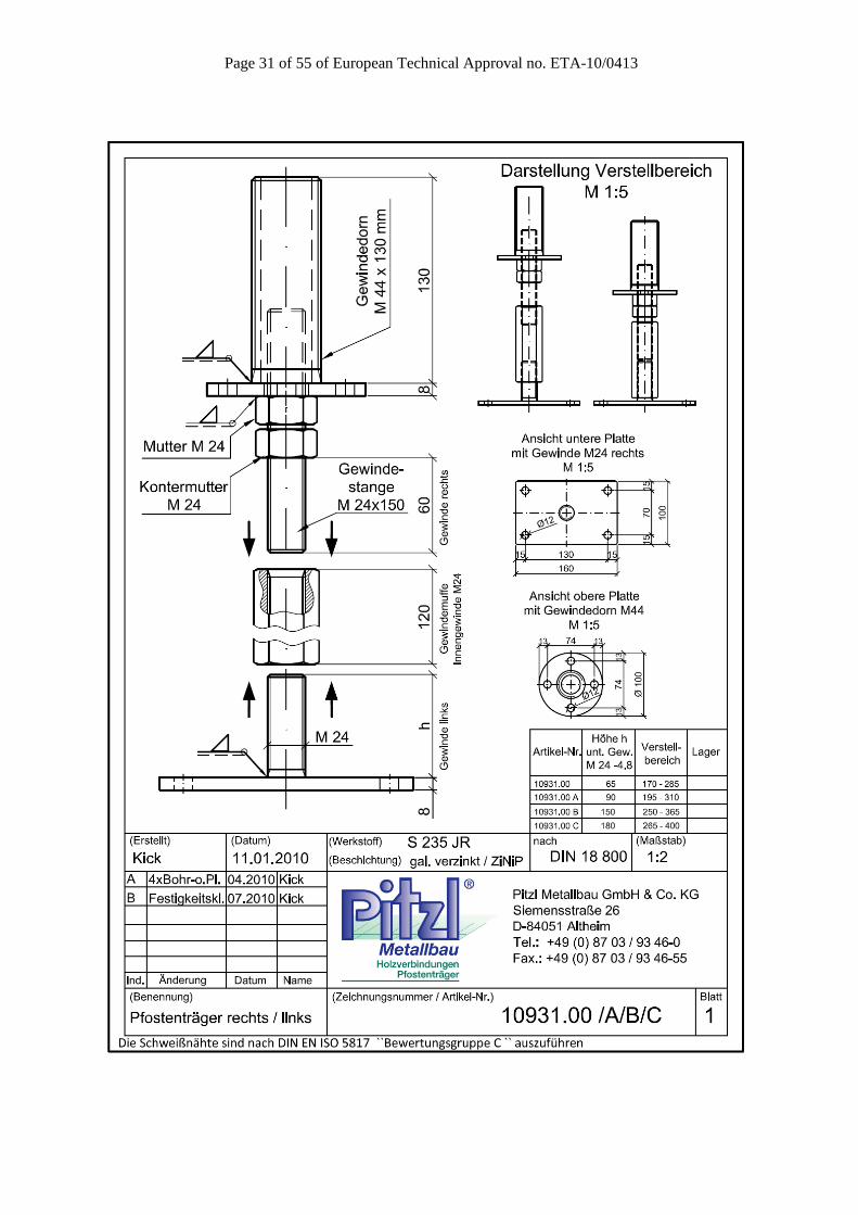
65 10931.00 4x F 10x120mm - 140/140 285 285 285
90 10931.00 A 4x F 10x120mm - 140/140 310 310 310
150 10931.00 B 4x F 10x120mm - 140/140 365 365 365
180 10931.00 C 4x F 10x120mm - 140/140 400 400 400
35 10931.10 4x F 10x120mm - 140/140 210 210 210
65 10931.30 4x F 10x120mm - 140/140 285 285 285
65 10931.30 6t 4x F 10x120mm - 140/140 295 295 295
Page 10 of 55 of European Technical Approval no. ETA-10/0413
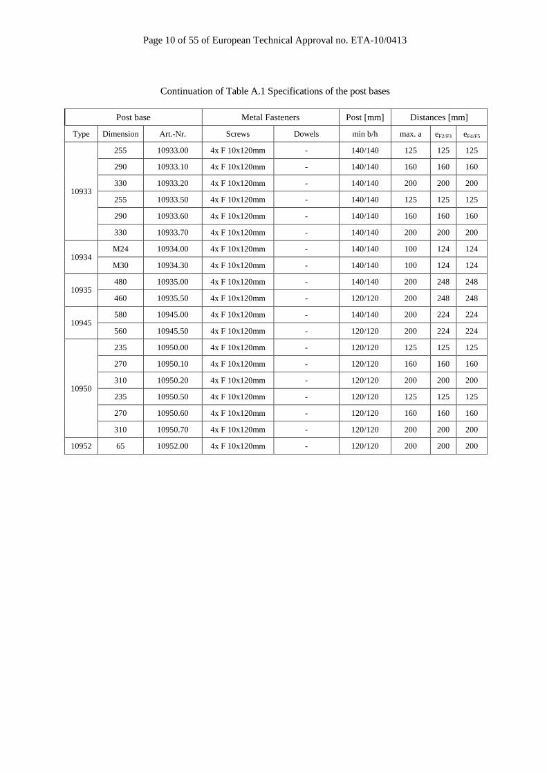
Continuation of Table A.1 Specifications of the post bases
Post base Metal Fasteners Post [mm] Distances [mm]
Type Dimension Art.-Nr. Screws Dowels min b/h max. a eF2/F3 eF4/F5
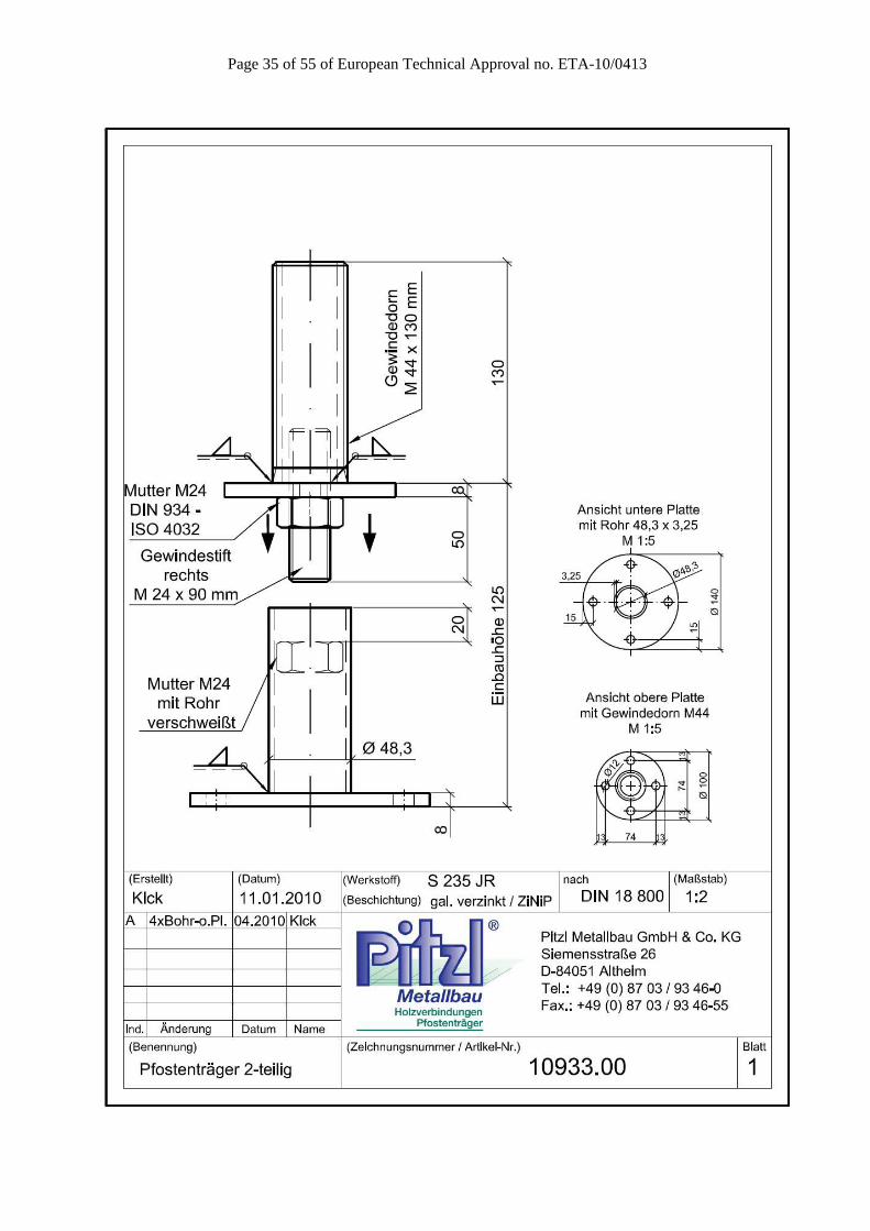
10933
255 10933.00 4x F 10x120mm - 140/140 125 125 125
290 10933.10 4x F 10x120mm - 140/140 160 160 160
330 10933.20 4x F 10x120mm - 140/140 200 200 200
255 10933.50 4x F 10x120mm - 140/140 125 125 125
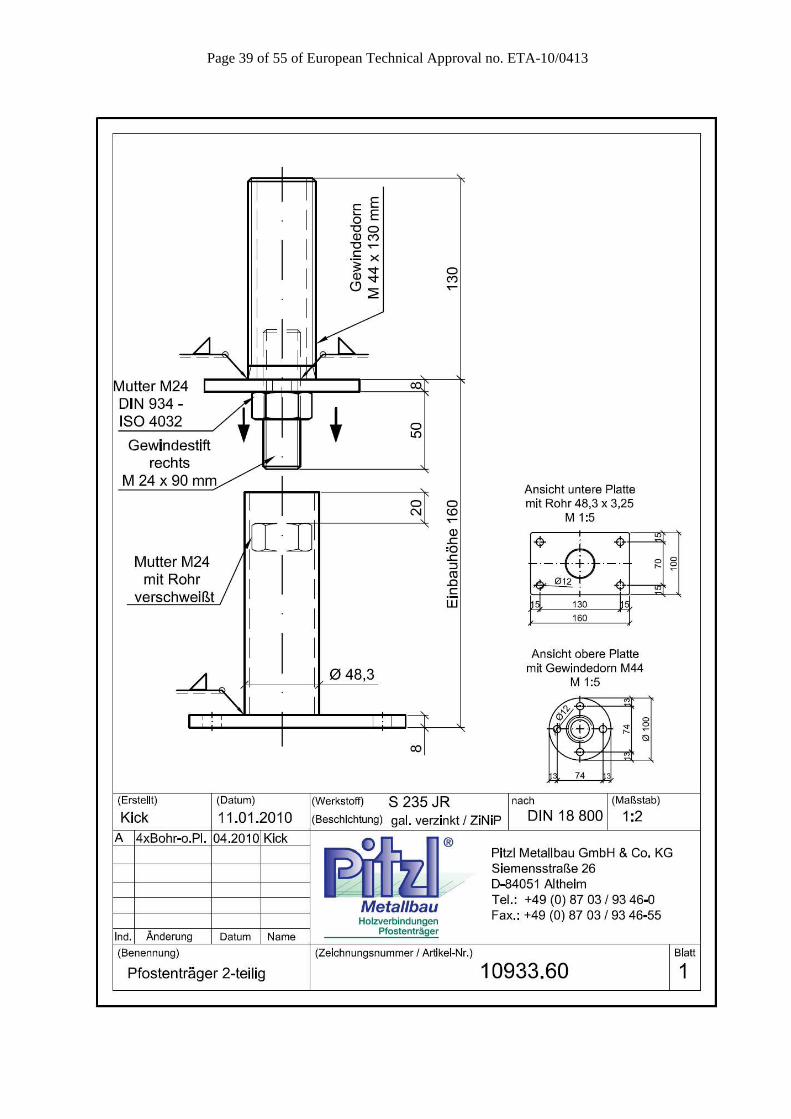
290 10933.60 4x F 10x120mm - 140/140 160 160 160
330 10933.70 4x F 10x120mm - 140/140 200 200 200
10934 M24 10934.00 4x F 10x120mm - 140/140 100 124 124
M30 10934.30 4x F 10x120mm - 140/140 100 124 124
10935 480 10935.00 4x F 10x120mm - 140/140 200 248 248
460 10935.50 4x F 10x120mm - 120/120 200 248 248
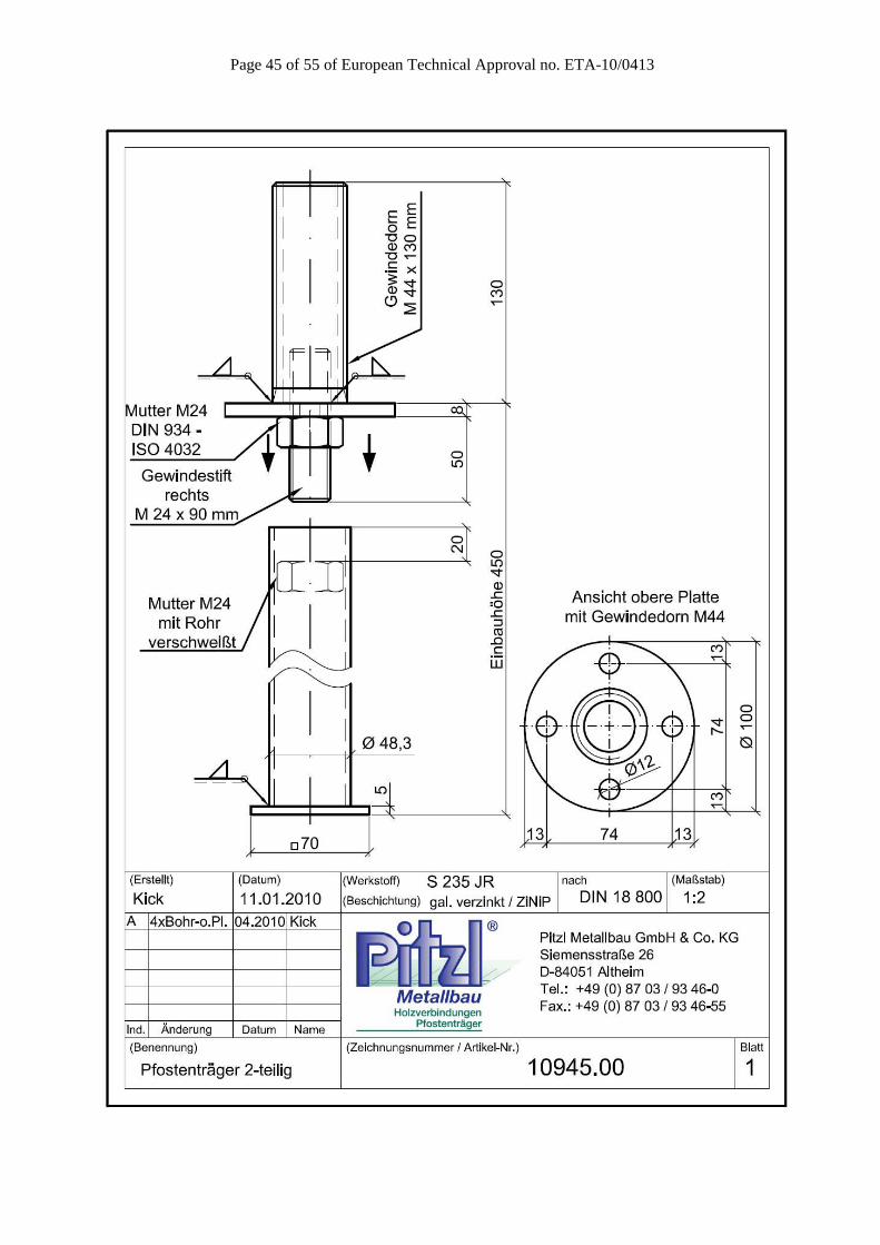
10945 580 10945.00 4x F 10x120mm - 140/140 200 224 224
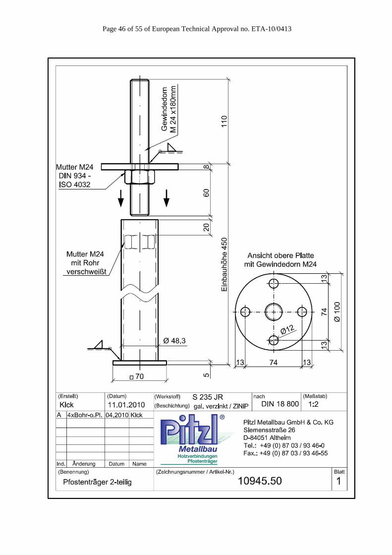
560 10945.50 4x F 10x120mm - 120/120 200 224 224
10950
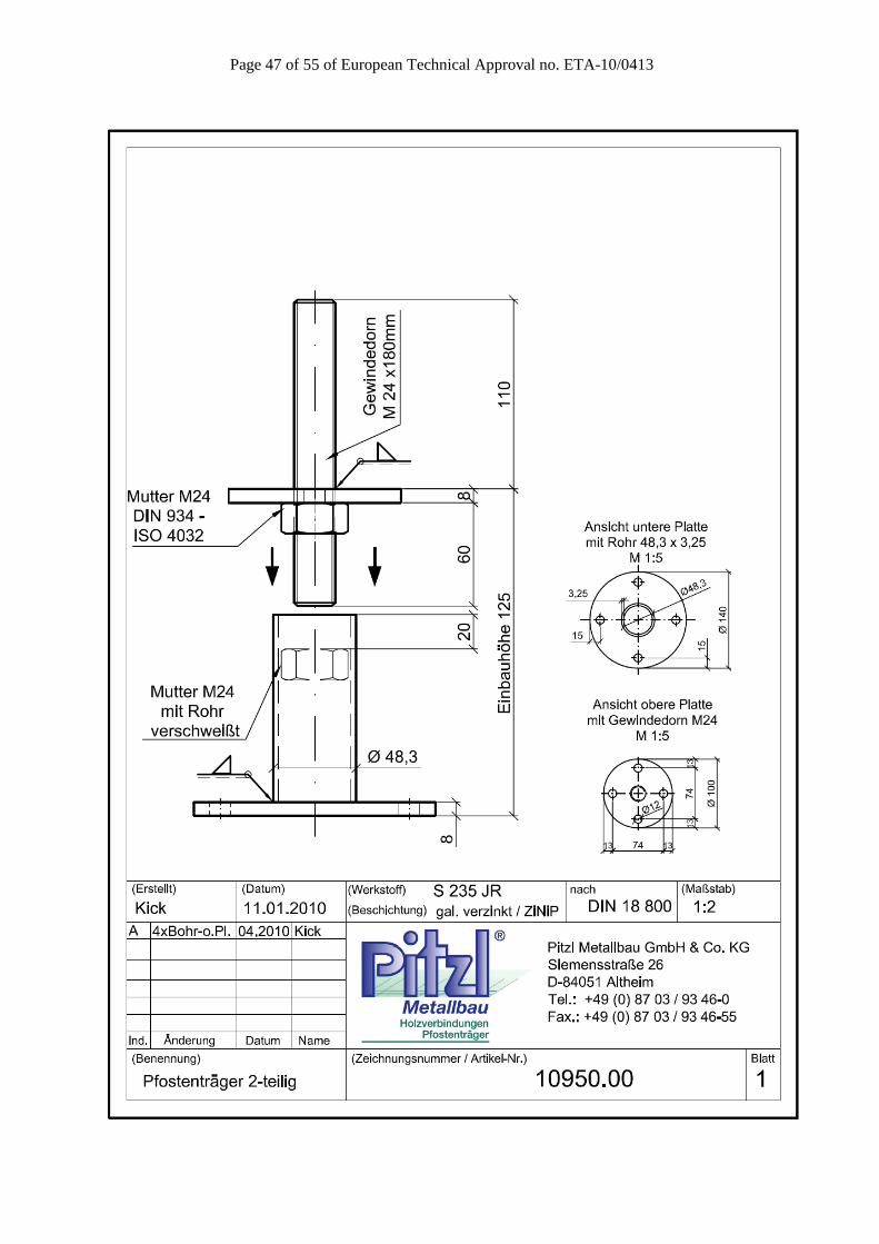
235 10950.00 4x F 10x120mm - 120/120 125 125 125
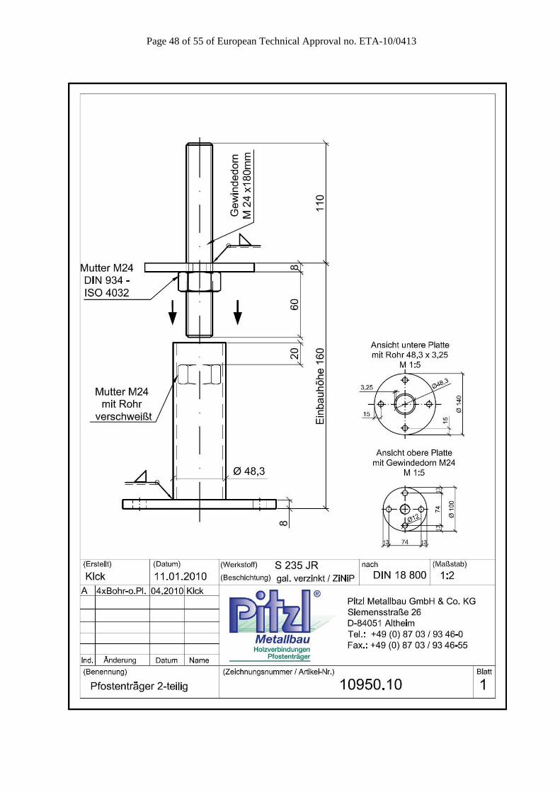
270 10950.10 4x F 10x120mm - 120/120 160 160 160
310 10950.20 4x F 10x120mm - 120/120 200 200 200
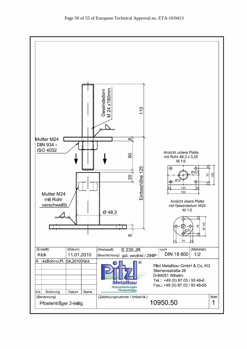
235 10950.50 4x F 10x120mm - 120/120 125 125 125
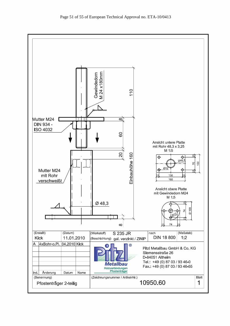
270 10950.60 4x F 10x120mm - 120/120 160 160 160
310 10950.70 4x F 10x120mm - 120/120 200 200 200
10952 65 10952.00 4x F 10x120mm - 120/120 200 200 200

Page 11 of 55 of European Technical Approval no. ETA-10/0413
Table A.2 Specifications of the metal fasteners according to EN 14592
Fastener type
(S235)
Size (mm) Finish
Diameter Length Threaded length
Dowels 12 mm Galvanic zinc coating
Screws 10 mm min 120 mm min 100 mm Galvanic zinc coating
The load-carrying-capacities of the metal fasteners were calculated according to Eurocode 5 for lateral loads. The contribution to the load-carrying capacity due to the rope effect was considered according to Eurocode 5.

Page 12 of 55 of European Technical Approval no. ETA-10/0413
Annex B Characteristic load-carrying capacities
Table B.1 Characteristic load-carrying capacities for post bases in kN
Post Base F1 (Compression) F1 (Tension) F23 F45
Type Threaded length [mm]
Timber Steel Timber Steel Timber Steel Timber Steel
1003.00
100 90,0 76,1 - 21,0 41,6 - 17,1 2,5 5,9 7,7 3,8 7,1
200 90,0 76,1 - 37,1 39,3 - 17,1 2,5 5,9 7,7 3,8 7,1
300 90,0 76,1 - 52,0 38,3 - 17,1 2,5 5,9 7,7 3,8 7,1
400 90,0 76,1 - 66,2 37,6 - 17,1 2,5 5,9 7,7 3,8 7,1
γm γm,1 - γm γm,0 - γm γm,0 γm,2 γm γm,0 γm,2
1007.00
100 90,0 76,1 - 20,8 26,0 - 17,1 2,8 5,9 12,4 3,7 15,2
200 90,0 76,1 - 37,2 25,3 - 17,1 2,8 5,9 12,4 3,7 15,2
300 90,0 76,1 - 52,1 24,6 - 17,1 2,8 5,9 12,4 3,7 15,2
γm γm,1 - γm γm,0 - γm γm,0 γm,2 γm γm,0 γm,2 Post Base F1 (Compression) F1 (Tension) F23 F45
Type Art.Nr. Timber Steel Timber Steel Timber Steel Timber Steel
1001 1001.00 90,0 76,1 - 16,3 47,3 - 7,9 7,2 - 7,9 7,2 -
γm γm,1 - γm γm,0 - γm γm,0 - γm γm,0 -
1005 1005.00 90,0 76,1 - 16,3 26,0 - 7,9 3,2 - 7,9 3,2 -
γm γm,1 - γm γm,0 - γm γm,0 - γm γm,0 -
1008 1008.00 189,9 159,7 - 16,3 81,8 - 11,0 15,3 19,6 11,0 15,3 19,6
γm γm,1 - γm γm,0 - γm γm,0 γm,2 γm γm,0 γm,2
1014.00
90,0 111,9 - - - - 7,9 2,4 - 7,9 2,4 -
Welded nut 90,0 111,9 - 16,3 16,8 - 7,9 2,4 - 7,9 2,4 -
Tension lug 90,0 111,9 - 8,7 3,6 4,5 7,9 2,4 - 7,9 2,4 -
γm γm,1 - γm γm,0 γm,2 γm γm,0 - γm γm,0 -
1015.00
90,0 75,2 - - - - 7,9 2,9 - 7,9 2,9 -
Welded nut 90,0 75,2 - 16,3 16,8 - 7,9 2,9 - 7,9 2,9 -
Tension lug 90,0 75,2 - 8,7 3,6 4,5 7,9 2,9 - 7,9 2,9 -
γm γm,1 - γm γm,0 γm,2 γm γm,0 γm,2 γm γm,0 γm,2
1016.00
90,0 75,2 - - - - 7,9 1,4 - 7,9 1,4 -
Welded nut 90,0 75,2 - 16,3 16,8 - 7,9 1,4 - 7,9 1,4 -
Tension lug 90,0 75,2 - 8,7 3,6 4,5 7,9 1,4 - 7,9 1,4 -
γm γm,1 - γm γm,0 γm,2 γm γm,0 γm,2 γm γm,0 γm,2
1016.30
90,0 145,7 - - - - 11,5 4,9 - 11,5 4,9 -
Welded nut 90,0 145,7 - 16,3 75,4 - 11,5 4,9 - 11,5 4,9 -
Tension lug 90,0 145,7 - 8,7 7,9 9,4 11,5 4,9 - 11,5 4,9 -
γm γm,1 - γm γm,0 γm,2 γm γm,0 γm,2 γm γm,0 γm,2
10920
10920.00 90,0 90,0 - 16,3 17,0 - 7,9 1,7 - 7,9 1,7 -
10920.00 A 90,0 81,1 - 16,3 17,0 - 7,9 1,5 - 7,9 1,5 -
10920.00 B 90,0 61,9 - 16,3 17,0 - 7,9 1,2 - 7,9 1,2 -
10920.00 C 90,0 54,0 - 16,3 17,0 - 7,9 1,1 - 7,9 1,1 -
10920.00 D 90,0 40,0 - 16,3 17,0 - 7,9 0,9 - 7,9 0,9 -
10920.30 90,0 169,1 - 16,3 45,8 - 11,5 6,2 - 11,5 6,2 -
γm γm,1 - γm(VM) γm,0 γm,2 γm γm,0 − γm γm,0 −

Page 13 of 55 of European Technical Approval no. ETA-10/0413
Continuation of Table B.1 Characteristic load-carrying capacities for post bases in kN
Post Base F1 (Compression) F1 (Tension) F23 F45
Type Art.Nr. Timber Steel Timber Steel Timber Steel Timber Steel
10921
10921.00 90,0 90,3 - 16,3 17,0 - 10,0 1,7 - 10,0 1,7 -
10921.00 A 90,0 81,1 - 16,3 17,0 - 10,0 1,5 - 10,0 1,5 -
10921.00 B 90,0 61,9 - 16,3 17,0 - 10,0 1,2 - 10,0 1,2 -
10921.00 C 90,0 54,0 - 16,3 17,0 - 10,0 1,1 - 10,0 1,1 -
10921.00 D 90,0 40,0 - 16,3 17,0 - 10,0 0,9 - 10,0 0,9 -
10921.10 90,0 118,9 - 16,3 17,0 - 10,0 4,1 - 10,0 4,1 -
10921.30 90,0 169,1 - 16,3 50,2 - 10,0 6,2 - 10,0 6,2 -
10921.30 6t 90,0 169,1 110,2 16,3 112,9 110,2 10,0 13,5 14,2 10,0 13,5 -
γm γm,1 - γm(VM) γm,0 γm,2 γm γm,0 γm,2 γm γm,0 -
10931
10931.00 90,0 64,2 - 16,3 30,2 - 10,0 3,2 4,8 10,0 3,2 4,8
10931.00 A 90,0 57,3 - 16,3 30,2 - 10,0 2,9 4,4 10,0 2,9 4,4
10931.00 B 90,0 45,0 - 16,3 30,2 - 10,0 2,5 3,7 10,0 2,5 3,7
10931.00 C 90,0 38,9 - 16,3 30,2 - 10,0 2,3 3,4 10,0 2,3 3,4
10931.10 90,0 89,5 - 16,3 30,2 - 10,0 4,3 6,5 10,0 4,3 6,5
10931.30 90,0 129,6 - 16,3 50,2 110,2 10,0 6,0 7,4 10,0 6,0 7,4
10931.30 6t 90,0 129,6 - 16,3 112,9 110,2 10,0 7,2 7,1 10,0 7,2 7,1
γm γm,1 - γm(VM) γm,0 γm,2 γm γm,0 γm,2 γm γm,0 γm,2
10933
10933.00 90,0 88,4 - 16,3 41,8 - 10,0 7,3 - 10,0 7,3 -
10933.10 90,0 88,4 - 16,3 41,8 - 10,0 5,6 - 10,0 5,6 -
10933.20 90,0 88,4 - 16,3 41,8 - 10,0 4,5 9,6 10,0 4,5 9,6
10933.50 90,0 88,4 - 16,3 27,7 - 10,0 5,5 - 10,0 5,5 -
10933.60 90,0 88,4 - 16,3 27,7 - 10,0 4,3 - 10,0 4,3 -
10933.70 90,0 88,4 - 16,3 27,7 - 10,0 3,4 9,6 10,0 3,4 9,6
γm γm,1 - γm(VM) γm,0 - γm γm,0 γm,2 γm γm,0 γm,2
10934
10934.00 90,0 91,0 - 16,3 144,8 - 10,0 11,2 10,0 11,2 -
10934.30 90,0 166,3 - 16,3 226,2 - 10,0 20,9 10,0 20,9 -
γm γm,1 - γm(VM) γm,0 - γm γm,0 − γm γm,0 −
10935
10935.00 90,0 88,4 - 16,3 88,4 77,1 10,0 13,2 9,6 10,0 13,2 9,6
10935.50 90,0 88,4 - 16,3 88,4 77,1 10,0 13,2 9,6 10,0 13,2 9,6
γm γm,1 - γm(VM) γm,0 γm,2 γm γm,0 γm,2 γm γm,0 γm,2
10945
10945.00 90,0 88,4 - 16,3 88,4 77,1 10,0 13,2 - 10,0 13,2 -
10945.50 90,0 88,4 - 16,3 88,4 77,1 10,0 13,2 - 10,0 13,2 -
γm γm,1 - γm(VM) γm,0 - γm γm,0 - γm γm,0 −
10950
10950.00 90,0 88,4 - 16,3 88,4 - 10,0 13,2 - 10,0 13,2 -
10950.10 90,0 88,4 - 16,3 0,0 - 10,0 87,4 - 10,0 87,4 -
10950.20 90,0 88,4 - 16,3 41,8 - 10,0 87,4 - 10,0 87,4 -
10950.50 90,0 88,4 - 16,3 27,7 - 10,0 87,4 - 10,0 87,4 -
10950.60 90,0 88,4 - 16,3 27,7 - 10,0 87,4 - 10,0 87,4 -
10950.70 90,0 88,4 - 16,3 27,7 - 10,0 87,4 - 10,0 87,4 -
γm γm,1 - γm(VM) γm,0 - γm γm,0 − γm γm,0 −
10952 10952.00 90,0 60,1 - 16,3 13,7 - 10,0 1,4 - 10,0 1,4 -
γm γm,1 - γm(VM) γm,0 γm,2 γm γm,0 − γm γm,0 −
Page 14 of 55 of European Technical Approval no. ETA-10/0413
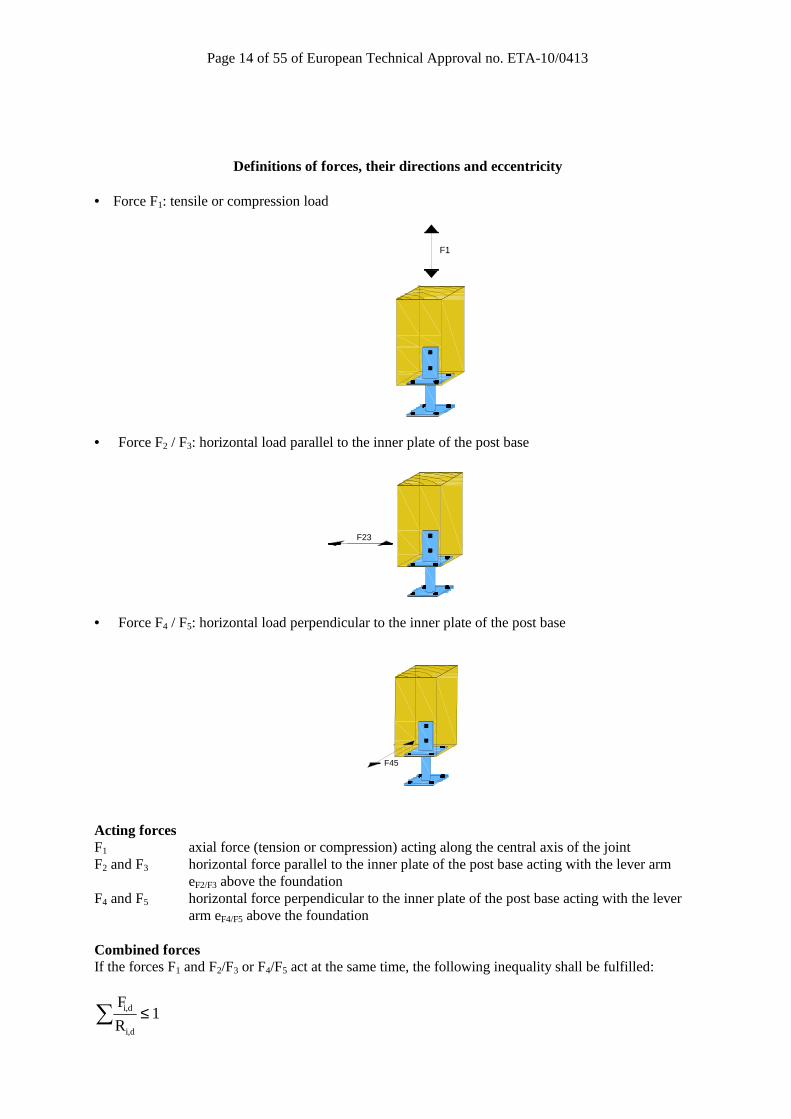
Definitions of forces, their directions and eccentricity • Force F1: tensile or compression load
F1
• Force F2 / F3: horizontal load parallel to the inner plate of the post base
F23
• Force F4 / F5: horizontal load perpendicular to the inner plate of the post base
F45
Acting forces F1 axial force (tension or compression) acting along the central axis of the joint F2 and F3 horizontal force parallel to the inner plate of the post base acting with the lever arm
eF2/F3 above the foundation F4 and F5 horizontal force perpendicular to the inner plate of the post base acting with the lever
arm eF4/F5 above the foundation Combined forces If the forces F1 and F2/F3 or F4/F5 act at the same time, the following inequality shall be fulfilled:
i,d
i,d
F1
R≤∑
Page 15 of 55 of European Technical Approval no. ETA-10/0413
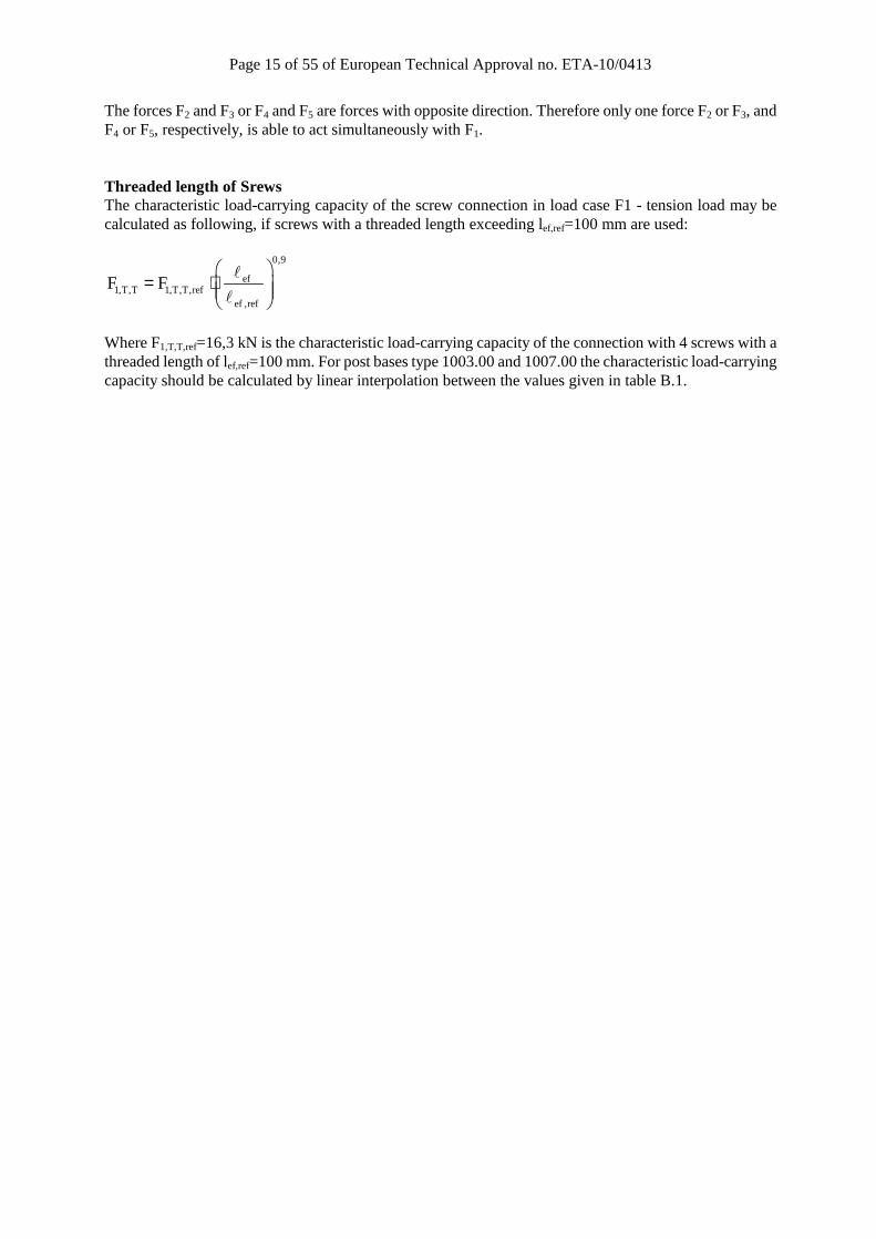
The forces F2 and F3 or F4 and F5 are forces with opposite direction. Therefore only one force F2 or F3, and F4 or F5, respectively, is able to act simultaneously with F1. Threaded length of Srews The characteristic load-carrying capacity of the screw connection in load case F1 - tension load may be calculated as following, if screws with a threaded length exceeding lef,ref=100 mm are used:
0,9
ef1,T,T 1,T,T,ref
ef ,ref
F F
= ⋅
l
l
Where F1,T,T,ref=16,3 kN is the characteristic load-carrying capacity of the connection with 4 screws with a threaded length of lef,ref=100 mm. For post bases type 1003.00 and 1007.00 the characteristic load-carrying capacity should be calculated by linear interpolation between the values given in table B.1.
Page 16 of 55 of European Technical Approval no. ETA-10/0413
Page 17 of 55 of European Technical Approval no. ETA-10/0413

Page 18 of 55 of European Technical Approval no. ETA-10/0413

Page 19 of 55 of European Technical Approval no. ETA-10/0413
Page 20 of 55 of European Technical Approval no. ETA-10/0413

Page 21 of 55 of European Technical Approval no. ETA-10/0413
Page 22 of 55 of European Technical Approval no. ETA-10/0413

Page 23 of 55 of European Technical Approval no. ETA-10/0413

Page 24 of 55 of European Technical Approval no. ETA-10/0413
Page 25 of 55 of European Technical Approval no. ETA-10/0413

Page 26 of 55 of European Technical Approval no. ETA-10/0413

Page 27 of 55 of European Technical Approval no. ETA-10/0413

Page 28 of 55 of European Technical Approval no. ETA-10/0413
Page 29 of 55 of European Technical Approval no. ETA-10/0413

Page 30 of 55 of European Technical Approval no. ETA-10/0413
Page 31 of 55 of European Technical Approval no. ETA-10/0413

Page 32 of 55 of European Technical Approval no. ETA-10/0413

Page 33 of 55 of European Technical Approval no. ETA-10/0413

Page 34 of 55 of European Technical Approval no. ETA-10/0413
Page 35 of 55 of European Technical Approval no. ETA-10/0413

Page 36 of 55 of European Technical Approval no. ETA-10/0413

Page 37 of 55 of European Technical Approval no. ETA-10/0413

Page 38 of 55 of European Technical Approval no. ETA-10/0413
Page 39 of 55 of European Technical Approval no. ETA-10/0413

Page 40 of 55 of European Technical Approval no. ETA-10/0413

Page 41 of 55 of European Technical Approval no. ETA-10/0413

Page 42 of 55 of European Technical Approval no. ETA-10/0413

Page 43 of 55 of European Technical Approval no. ETA-10/0413

Page 44 of 55 of European Technical Approval no. ETA-10/0413
Page 45 of 55 of European Technical Approval no. ETA-10/0413
Page 46 of 55 of European Technical Approval no. ETA-10/0413
Page 47 of 55 of European Technical Approval no. ETA-10/0413
Page 48 of 55 of European Technical Approval no. ETA-10/0413

Page 49 of 55 of European Technical Approval no. ETA-10/0413
Page 50 of 55 of European Technical Approval no. ETA-10/0413
Page 51 of 55 of European Technical Approval no. ETA-10/0413
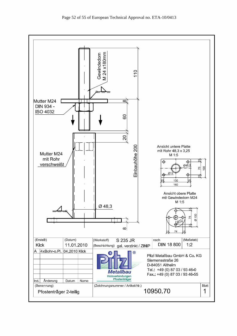
Page 52 of 55 of European Technical Approval no. ETA-10/0413

Page 53 of 55 of European Technical Approval no. ETA-10/0413

Page 54 of 55 of European Technical Approval no. ETA-10/0413

Page 55 of 55 of European Technical Approval no. ETA-10/0413