european railway agency - nist · 2011-06-13 · european railway agency interoperability unit...
TRANSCRIPT
European Railway Agency
INTEROPERABILITY UNIT
REVISION OF THE WAGON TSI
TRANS-EUROPEAN CONVENTIONAL RAIL SYSTEM
SUBSYSTEM ROLLING STOCK
TSI “WAGON”
Reference: IU-WAG TSI- Preliminary draft 1.0.doc Document
type:
Technical specifications for Interoperability
Version : Preliminary draft 1.0 Status : DRAFT
Date : 31 January 2011
Edited by Reviewed by Approved by
Name Andreas SCHIRMER Gianvittorio TAVOLA
Mikael AHO Denis BIASIN
Position Project Officers Adviser Head of Unit
Date
&
Signature
Legenda: Text in yellow: references, links, etc. To be verified
ERA INTEROPERABILITY UNIT
IU-WAG TSI- Preliminary draft 1.0.doc
Version Preliminary draft 1.0 PAGE 2 OF 63
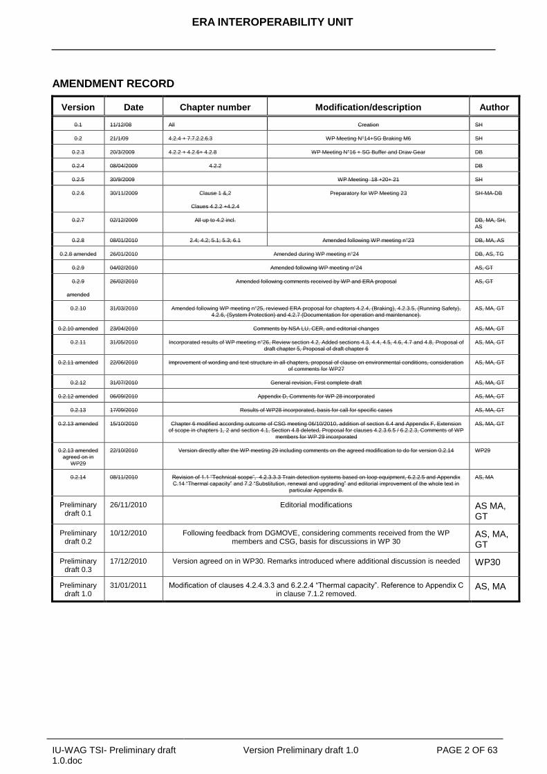
AMENDMENT RECORD
Version Date Chapter number Modification/description Author
0.1 11/12/08 All Creation SH
0.2 21/1/09 4.2.4 + 7.7.2.2.6.3 WP Meeting N°14+SG Braking M6 SH
0.2.3 20/3/2009 4.2.2 + 4.2.6+ 4.2.8 WP Meeting N°16 + SG Buffer and Draw Gear DB
0.2.4 08/04/2009 4.2.2 DB
0.2.5 30/9/2009 WP Meeting 18 +20+ 21 SH
0.2.6 30/11/2009 Clause 1 &,2
Claues 4.2.2 +4.2.4
Preparatory for WP Meeting 23 SH-MA-DB
0.2.7 02/12/2009 All up to 4.2 incl. DB, MA, SH,
AS
0.2.8 08/01/2010 2.4; 4.2; 5.1; 5.3; 6.1 Amended following WP meeting n°23 DB, MA, AS
0.2.8 amended 26/01/2010 Amended during WP meeting n°24 DB, AS, TG
0.2.9 04/02/2010 Amended following WP meeting n°24 AS, GT
0.2.9
amended
26/02/2010 Amended following comments received by WP and ERA proposal AS, GT
0.2.10 31/03/2010 Amended following WP meeting n°25, reviewed ERA proposal for chapters 4.2.4, (Braking), 4.2.3.5, (Running Safety),
4.2.6, (System Protection) and 4.2.7 (Documentation for operation and maintenance).
AS, MA, GT
0.2.10 amended 23/04/2010 Comments by NSA LU, CER, and editorial changes AS, MA, GT
0.2.11 31/05/2010 Incorporated results of WP meeting n°26, Review section 4.2, Added sections 4.3, 4.4, 4.5, 4.6, 4.7 and 4.8, Proposal of
draft chapter 5, Proposal of draft chapter 6
AS, MA, GT
0.2.11 amended 22/06/2010 Improvement of wording and text structure in all chapters, proposal of clause on environmental conditions, consideration
of comments for WP27
AS, MA, GT
0.2.12 31/07/2010 General revision, First complete draft AS, MA, GT
0.2.12 amended 06/09/2010 Appendix D, Comments for WP 28 incorporated AS, MA, GT
0.2.13 17/09/2010 Results of WP28 incorporated, basis for call for specific cases AS, MA, GT
0.2.13 amended 15/10/2010 Chapter 6 modified according outcome of CSG meeting 06/10/2010, addition of section 6.4 and Appendix F, Extension
of scope in chapters 1, 2 and section 4.1, Section 4.8 deleted, Proposal for clauses 4.2.3.6.5 / 6.2.2.3, Comments of WP
members for WP 29 incorporated
AS, MA, GT
0.2.13 amended
agreed on in
WP29
22/10/2010 Version directly after the WP meeting 29 including comments on the agreed modification to do for version 0.2.14 WP29
0.2.14 08/11/2010 Revision of 1.1 “Technical scope”, 4.2.3.3.3 Train detection systems based on loop equipment, 6.2.2.5 and Appendix
C.14 “Thermal capacity” and 7.2 “Substitution, renewal and upgrading” and editorial improvement of the whole text in
particular Appendix B.
AS, MA
Preliminary draft 0.1
26/11/2010 Editorial modifications AS MA, GT
Preliminary draft 0.2
10/12/2010 Following feedback from DGMOVE, considering comments received from the WP members and CSG, basis for discussions in WP 30
AS, MA, GT
Preliminary draft 0.3
17/12/2010 Version agreed on in WP30. Remarks introduced where additional discussion is needed WP30
Preliminary draft 1.0
31/01/2011 Modification of clauses 4.2.4.3.3 and 6.2.2.4 “Thermal capacity”. Reference to Appendix C in clause 7.1.2 removed.
AS, MA

ERA INTEROPERABILITY UNIT
IU-WAG TSI- Preliminary draft 1.0.doc
Version Preliminary draft 1.0 PAGE 3 OF 63
TABLE OF CONTENTS
1. INTRODUCTION ....................................................................................................................... 7
1.1 Technical Scope ............................................................................................................................ 7
1.2 Geographical Scope ..................................................................................................................... 7
1.3 Content OF THIS TSI ..................................................................................................................... 7
1.4 REFERENCE DOCUMENTS .......................................................................................................... 8
2. SCOPE AND DEFINITION OF SUBSYSTEM ......................................................................... 10
3. ESSENTIAL REQUIREMENTS ............................................................................................... 11
4. CHARACTERISATION OF THE SUBSYSTEM ....................................................................... 13
4.1 INTRODUCTION ........................................................................................................................... 13
4.2 FUNCTIONAL AND TECHNICAL SPECIFICATIONS OF THE SUBSYSTEM .............................. 13
4.2.1 General .................................................................................................................................................................... 13
4.2.2 Structures and mechanical part ............................................................................................................................... 14
4.2.2.1. Mechanical Interface ......................................................................................................................................... 14
4.2.2.1.1 End coupling ................................................................................................................................................ 14
4.2.2.1.2 Inner coupling ............................................................................................................................................... 14
4.2.2.2. Strength of unit .................................................................................................................................................. 14
4.2.3 Track interaction and gauging ................................................................................................................................. 14
4.2.3.1. Gauging............................................................................................................................................................. 14
4.2.3.2. Compatibility with load carrying capacity of lines .............................................................................................. 15
4.2.3.3 Compatibility with train detection systems ......................................................................................................... 15
4.2.3.3.1 Train detection systems based on track circuits .......................................................................................... 15
4.2.3.3.2 Train detection systems based on axle counters ......................................................................................... 15
4.2.3.3.3 Train detection systems based on loop equipment ...................................................................................... 15
4.2.3.4 Axle bearing condition monitoring ...................................................................................................................... 16
4.2.3.5 Running safety ................................................................................................................................................... 16
4.2.3.5.1 Safety against derailment running on twisted track ...................................................................................... 16
4.2.3.5.2 Running dynamic behaviour ......................................................................................................................... 16
4.2.3.6 Running gear...................................................................................................................................................... 16
4.2.3.6.1 Structural design of bogie frame .................................................................................................................. 17
4.2.3.6.2 Characteristics of wheelsets......................................................................................................................... 17
4.2.3.6.3 Characteristics of wheels ............................................................................................................................. 18
4.2.3.6.4 Characteristics of axles ................................................................................................................................ 19
4.2.3.6.5 Axle boxes / bearings ................................................................................................................................... 19
4.2.3.6.6 Variable gauge wheelsets ............................................................................................................................ 19
ERA INTEROPERABILITY UNIT
IU-WAG TSI- Preliminary draft 1.0.doc
Version Preliminary draft 1.0 PAGE 4 OF 63
4.2.4 Brake ...................................................................................................................................................................... 20
4.2.4.1 General .............................................................................................................................................................. 20
4.2.4.2 Safety requirements ........................................................................................................................................... 20
4.2.4.3.1 General functional requirements ............................................................................................................... 21
4.2.4.3.2. Brake performance ................................................................................................................................... 21
4.2.4.3.2.1 In-service brake ................................................................................................................................... 21
4.2.4.3.2.2 Parking brake ...................................................................................................................................... 21
4.2.4.3.3 Thermal capacity ....................................................................................................................................... 22
4.2.4.3.4 Wheel slide protection (WSP) ................................................................................................................... 22
4.2.5 Environmental conditions......................................................................................................................................... 22
4.2.6 System protection .................................................................................................................................................... 23
4.2.6.1 Fire safety .......................................................................................................................................................... 23
4.2.6.1.1 General......................................................................................................................................................... 23
4.2.6.1.2. Functional and technical specification ......................................................................................................... 23
4.2.6.1.2.1 Barriers ................................................................................................................................................... 23
4.2.6.1.2.2 Materials ................................................................................................................................................. 23
4.2.6.1.2.3 Cables .................................................................................................................................................... 23
4.2.6.1.2.4 Flammable liquids .................................................................................................................................. 23
4.2.6.1.2.5 Running capability .................................................................................................................................. 24
4.2.6.2. Protection against electrical hazards ................................................................................................................ 24
4.2.6.2.1 Protective measures against indirect contact (protective bonding) .............................................................. 24
4.2.6.2.2 Protective measures against direct contact ................................................................................................. 24
4.2.6.3 Attachment devices for rear-end signal.............................................................................................................. 24
4.3 Functional and technical specification of the interfaces ......................................................... 25
4.3.1 Interface with infrastructure subsystem ................................................................................................................... 25
4.3.2 Interface with operation subsystem ......................................................................................................................... 25
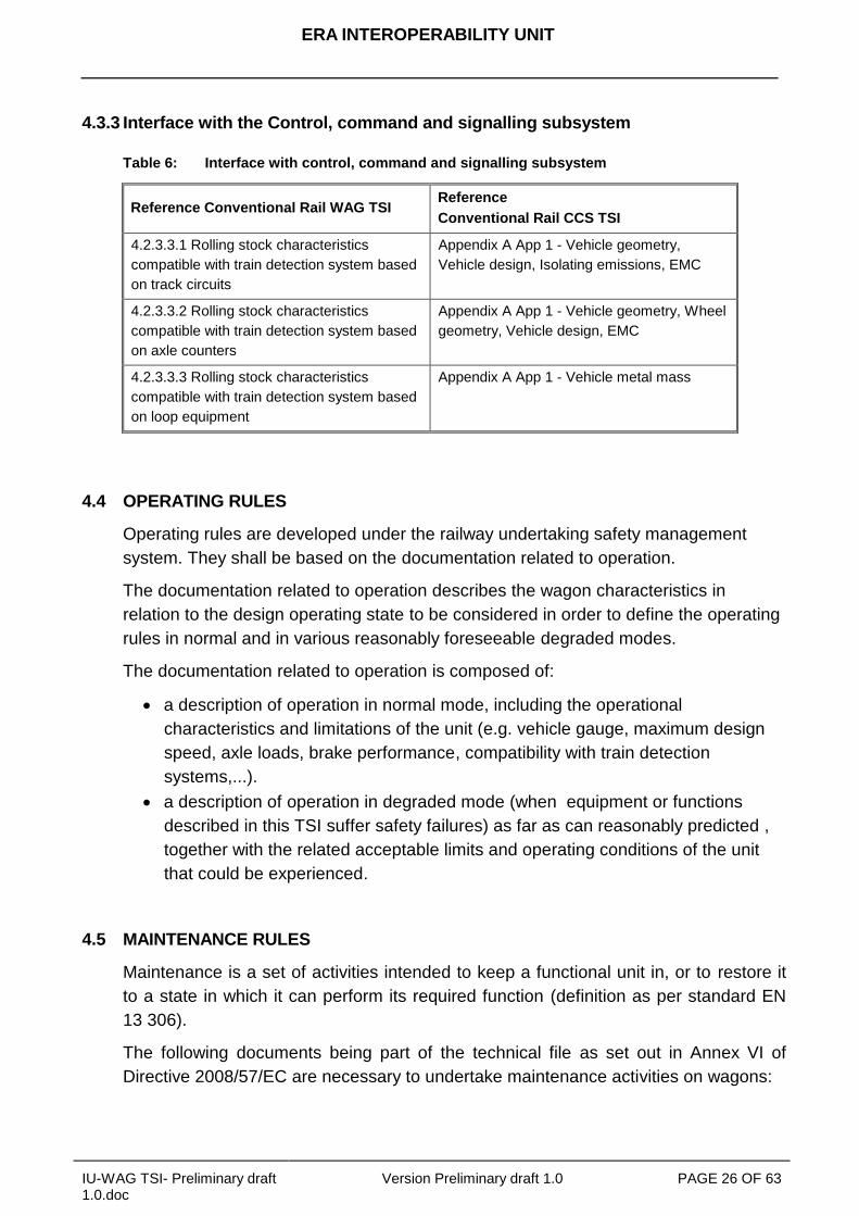
4.3.3 Interface with the Control, command and signalling subsystem .............................................................................. 26
4.4 Operating rules ........................................................................................................................... 26
4.5 Maintenance rules ....................................................................................................................... 26
4.5.1 General documentation ........................................................................................................................................... 27
4.5.2 Maintenance design justification file ........................................................................................................................ 27
4.5.3 Maintenance description file .................................................................................................................................... 27
4.6 Professional competencies ........................................................................................................ 28
4.7 Health and safety conditions ..................................................................................................... 29
5 INTEROPERABILITY CONSTITUENTS ................................................................................. 30
5.1 General ........................................................................................................................................ 30
5.2 INNOVATIVE SOLUTIONS ........................................................................................................... 30
ERA INTEROPERABILITY UNIT
IU-WAG TSI- Preliminary draft 1.0.doc
Version Preliminary draft 1.0 PAGE 5 OF 63
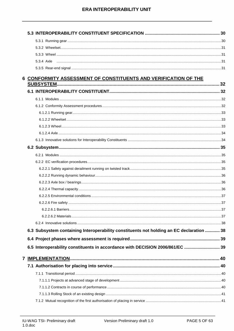
5.3 INTEROPERABILITY CONSTITUENT SPECIFICATION ............................................................. 30
5.3.1 Running gear ........................................................................................................................................................... 30
5.3.2 Wheelset.................................................................................................................................................................. 31
5.3.3 Wheel ...................................................................................................................................................................... 31
5.3.4 Axle ...................................................................................................................................................................... 31
5.3.5 Rear-end signal ....................................................................................................................................................... 31
6 CONFORMITY ASSESSMENT OF CONSTITUENTS AND VERIFICATION OF THE
SUBSYSTEM........................................................................................................................... 32
6.1 INTEROPERABILITY CONSTITUENT.......................................................................................... 32
6.1.1 Modules ................................................................................................................................................................... 32
6.1.2 Conformity Assessment procedures ........................................................................................................................ 32
6.1.2.1 Running gear...................................................................................................................................................... 33
6.1.2.2 Wheelset ............................................................................................................................................................ 33
6.1.2.3 Wheel ................................................................................................................................................................. 33
6.1.2.4 Axle .................................................................................................................................................................... 34
6.1.3 Innovative solutions for Interoperability Constituents .............................................................................................. 34
6.2 Subsystem ................................................................................................................................... 35
6.2.1 Modules ................................................................................................................................................................... 35
6.2.2 EC verification procedures ....................................................................................................................................... 35
6.2.2.1 Safety against derailment running on twisted track ............................................................................................ 35
6.2.2.2 Running dynamic behaviour ............................................................................................................................... 36
6.2.2.3 Axle box / bearings ............................................................................................................................................. 36
6.2.2.4 Thermal capacity ................................................................................................................................................ 36
6.2.2.5 Environmental conditions ................................................................................................................................... 37
6.2.2.6 Fire safety .......................................................................................................................................................... 37
6.2.2.6.1 Barriers ......................................................................................................................................................... 37
6.2.2.6.2 Materials ....................................................................................................................................................... 37
6.2.4 Innovative solutions ................................................................................................................................................. 38
6.3 Subsystem containing Interoperability constituents not holding an EC declaration ............ 38
6.4 Project phases where assessment is required ......................................................................... 39
6.5 Interoperability constituents in accordance with DECISION 2006/861/EC ............................. 39
7 IMPLEMENTATION ................................................................................................................. 40
7.1 Authorisation for placing into service ....................................................................................... 40
7.1.1 Transitional period ................................................................................................................................................... 40
7.1.1.1 Projects at advanced stage of development ...................................................................................................... 40
7.1.1.2 Contracts in course of performance ................................................................................................................... 40
7.1.1.3 Rolling Stock of an existing design .................................................................................................................... 41
7.1.2 Mutual recognition of the first authorisation of placing in service ............................................................................ 41
ERA INTEROPERABILITY UNIT
IU-WAG TSI- Preliminary draft 1.0.doc
Version Preliminary draft 1.0 PAGE 6 OF 63
7.2 substitution, renewal and upgrading......................................................................................... 41
7.3 Specific cases ............................................................................................................................. 42
7.3.1 Introduction .............................................................................................................................................................. 42
7.3.2 List of specific cases ................................................................................................................................................ 43
APPENDIX A OPEN POINTS ................................................................................................... 44
APPENDIX B SPECIFIC PROCEDURES FOR RUNNING DYNAMICS................................... 45
APPENDIX C ADDITIONAL OPTIONAL CONDITIONS FOR UNITS USED UNDER
CERTAIN OPERATIVE REGIMES ..................................................................... 51
APPENDIX D STANDARDS OR NORMATIVE DOCUMENTS REFERRED TO IN THIS
TSI ...................................................................................................................... 59
APPENDIX E REAR-END SIGNAL .......................................................................................... 62
APPENDIX F ASSESSMENT ASSIGNED TO THE PRODUCTION PHASES ........................ 63
ERA INTEROPERABILITY UNIT
IU-WAG TSI- Preliminary draft 1.0.doc
Version Preliminary draft 1.0 PAGE 7 OF 63
1. INTRODUCTION
1.1 TECHNICAL SCOPE
In general a Technical Specification for Interoperability (TSI) is a specification by
which a particular subsystem is addressed in order
to meet the essential requirements and
to ensure the interoperability
as described in the Directive 2008/57/EC. This TSI concerns the rolling stock
subsystem shown in point 1 of Appendix II to the Directive 2008/57/EC and within the
rolling stock subsystem this TSI covers freight wagons including vehicles designed to
carry lorries. In the following this part of the subsystem is called “wagon”.
The application of this TSI is limited to wagons with a maximum operating speed
lower than 190 km/h and which are intended to be operated on networks with a
nominal track gauge of 1435 mm, 1520 mm, 1524 mm, 1600 mm and 1668 mm.
1.2 GEOGRAPHICAL SCOPE
The geographical scope of this TSI is the whole rail system, in accordance with
Article 1 of Directive 2008/57/EC.
1.3 CONTENT OF THIS TSI
In accordance with Article 5(3) of the Directive, this TSI:
a) indicates its intended scope (chapter 2);
b) lays down essential requirements for the concerned domain and for its interfaces
vis-à-vis other subsystems (chapter 3);
c) establishes the functional and technical specifications to be met by the
subsystem and its interfaces vis-à-vis other subsystems (chapter 4);
d) determines the interoperability constituents and interfaces which must be
covered by European specifications, including European standards, which are
necessary to achieve interoperability within the rail system (chapter 5);
e) states, in each case under consideration, which procedures are to be used in
order to assess the conformity or the suitability for use of the interoperability
constituents on the one hand, or the „EC‟ verification of the subsystems on the
other hand (chapter 6);
f) indicates the strategy for implementing the TSIs (chapter 7);
ERA INTEROPERABILITY UNIT
IU-WAG TSI- Preliminary draft 1.0.doc
Version Preliminary draft 1.0 PAGE 8 OF 63
g) indicates, for the staff concerned, the professional qualifications and health and
safety conditions at work required for the operation and maintenance of the
above subsystem, as well as for the implementation of this TSI ( chapter 4).
In accordance with Article 5(5) of the Directive, provision may be made for specific
cases for each TSI. Such provisions are indicated in chapter 7.
As far as possible the assessment procedure for the requirements in section 4.2 are
defined in chapter 6. In these cases the text of section 4.2 is referring to the
corresponding clauses and sub clauses of chapter 6. If for a particular basic
parameter the separation of requirements and assessment procedures is not feasible,
no reference is given.
1.4 REFERENCE DOCUMENTS
CR WAG TSI: published in the Official Journal L344, - Commission Decision
2006/861/EC of 28 July 2006, amended by Commission Decision 2009/107/EC
of 23 January 2009.
Legislative measures in force:
Directive 2008/57/EC,
Directive 2004/49/EC,
Conventional Rail Control, command and signalling TSI: Commission Decision
2006/679/EC1,
High Speed RST TSI: Commission Decision 2008/232/EC2,
High speed Infrastructure TSI: Commission Decision 2008/217/EC3,
Accessibility for people with reduced mobility (PRM) TSI: Commission Decision
2008/164/EC4,
Safety in Railway Tunnels (SRT) TSI: Commission Decision 2008/163/EC5,
Conventional Rail Noise TSI: Commission Decision 2006/66/EC6,
Conventional Rail Freight Wagons TSI (CR WAG TSI): Commission Decision
2006/861/EC7, amended by Commission Decision 2009/107/EC
8,
Conventional Rail Operation and Traffic Management (OPE) TSI: Commission
Decision 2006/920/EC9, amended by Commission Decision 2009/107/EC
10 and
2010/640/EU,
1 OJ L 284, 28.03.2006, p.1
2 OJ L 84, 26.03.2008, p.132
3 OJ L 6440, 19.03.2008, p.105
4 OJ L 64, 07.03.2008, p.72
5 OJ L 64, 07.03.2008, p.1
6 OJ L 37, 08.02.2006, p.1
7 OJ L 344, 8.12.2006, p.1
8 OJ L 45, 14.02.2009, p.1
9 OJ L 359, 18.12.2006, p.1
ERA INTEROPERABILITY UNIT
IU-WAG TSI- Preliminary draft 1.0.doc
Version Preliminary draft 1.0 PAGE 9 OF 63
Common Safety Methods (CSM): Commission Regulation (EC) No 352/200911
.
Description of modules for conformity assessment: Commission descision
2010/713/EU12
.
Legislative measures under adoption process:
Conventional Rail Infrastructure TSI (CR INF TSI)
Conventional Rail Energy TSI (CR ENE TSI)
Recast of TSI OPE CR
Commission Decision on ERATV.
Legislative measures under development:
Telematic application for passengers TSI (TAP-TSI)
10
OJ L 45, 14.02.2009, p. 1 11
OJ L 108, 29.04.2009, p.4 12
OJ L 319, 04.12.2010, p.1
ERA INTEROPERABILITY UNIT
IU-WAG TSI- Preliminary draft 1.0.doc
Version Preliminary draft 1.0 PAGE 10 OF 63
2. SCOPE AND DEFINITION OF SUBSYSTEM
This TSI is applicable to “freight wagons including vehicles designed to carry lorries”
of the rail system as referred to in Appendix I section 1.2 and 2.2 and extended
according to Appendix I chapter 4 of the Directive 2008/57/EC. In the following this
part of the subsystem is called “wagon”.
The other vehicles listed in point 1.2 of Appendix I to the Directive 2008/57/EC,
especially mobile railway infrastructure construction and maintenance equipment, are
in the scope of TSI “Locomotives and passenger rolling stock” (CR LOC&PAS TSI).
Units designed to carry
motor vehicles with their passengers on board or
motor vehicles without passengers on board but intended to be integrated in
passenger trains (car carriers)
are excluded from the scope of this TSI.
This TSI applies to new, upgraded or renewed wagons intended to be placed in
service after the entry into force of this TSI.
The documents necessary for the procedures of maintenance and operation are
specified in section 4.4 and 4.5 of this TSI.
The additional optional requirements for units used under certain operative regimes
are set out in Appendix C of this TSI.
In the present TSI the following definitions are used:
A unit is the generic term used to name the rolling stock. It is subject to the
application of this TSI, and therefore subject to the EC verification procedure.
A unit can consist of:
a freight wagon that can be operated separately, featuring an individual frame
mounted on its own set of wheels or
a rake of permanently connected elements, those elements cannot be operated
separately or
separate rail bogies connected to a compatible road vehicle the combination of
which form a rake of a rail compatible system.
ERA INTEROPERABILITY UNIT
IU-WAG TSI- Preliminary draft 1.0.doc
Version Preliminary draft 1.0 PAGE 11 OF 63
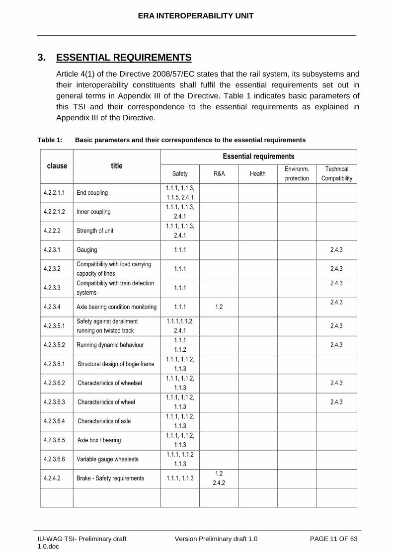
3. ESSENTIAL REQUIREMENTS
Article 4(1) of the Directive 2008/57/EC states that the rail system, its subsystems and
their interoperability constituents shall fulfil the essential requirements set out in
general terms in Appendix III of the Directive. Table 1 indicates basic parameters of
this TSI and their correspondence to the essential requirements as explained in
Appendix III of the Directive.
Table 1: Basic parameters and their correspondence to the essential requirements
clause title
Essential requirements
Safety R&A Health Environm.
protection
Technical
Compatibility
4.2.2.1.1 End coupling 1.1.1, 1.1.3,
1.1.5, 2.4.1
4.2.2.1.2 Inner coupling 1.1.1, 1.1.3,
2.4.1
4.2.2.2 Strength of unit 1.1.1, 1.1.3,
2.4.1
4.2.3.1 Gauging 1.1.1 2.4.3
4.2.3.2 Compatibility with load carrying
capacity of lines 1.1.1 2.4.3
4.2.3.3 Compatibility with train detection
systems 1.1.1
2.4.3
4.2.3.4 Axle bearing condition monitoring 1.1.1 1.2 2.4.3
4.2.3.5.1 Safety against derailment
running on twisted track
1.1.1,1.1.2,
2.4.1 2.4.3
4.2.3.5.2 Running dynamic behaviour 1.1.1
1.1.2 2.4.3
4.2.3.6.1 Structural design of bogie frame 1.1.1, 1.1.2,
1.1.3
4.2.3.6.2 Characteristics of wheelset 1.1.1, 1.1.2,
1.1.3 2.4.3
4.2.3.6.3 Characteristics of wheel 1.1.1, 1.1.2,
1.1.3 2.4.3
4.2.3.6.4 Characteristics of axle 1.1.1, 1.1.2,
1.1.3
4.2.3.6.5 Axle box / bearing 1.1.1, 1.1.2,
1.1.3
4.2.3.6.6 Variable gauge wheelsets 1.1.1, 1.1.2
1.1.3
4.2.4.2 Brake - Safety requirements 1.1.1, 1.1.3 1.2
2.4.2

ERA INTEROPERABILITY UNIT
IU-WAG TSI- Preliminary draft 1.0.doc
Version Preliminary draft 1.0 PAGE 12 OF 63
clause title
Essential requirements
Safety R&A Health Environment
al protection
Technical
Compatibility
4.2.4.3.1 Brake - General functional
requirements
1.1.1
2.4.1 2.4.2
4.2.4.3.2.1 Brake performance – In-service
brake
1.1.1, 1.1.2
2.4.1 2.4.2 1.5
4.2.4.3.2.2 Brake performance – Parking
brake 2.4.1 2.4.3
4.2.4.3.3 Brake - Thermal capacity 1.1.1, 1.1.3
2.4.1 2.4.3
4.2.4.3.4 Brake - Wheel slide protection
(WSP) 2.4.1 2.4.2
4.2.5 Environmental conditions 1.1.1
1.1.2 2.4.3
4.2.6.1 Fire safety - General 1.1.1
1.1.4
4.2.6.1.2.1 Fire safety - Barriers 1.1.4
4.2.6.1.2.2 Fire safety - Materials 1.1.4 1.3.2 1.4.2
4.2.6.1.2.3 Fire safety - Cables 1.1.4
1.1.5 1.3.2 1.4.2
4.2.6.1.2.4 Fire safety – Flammable liquids 1.1.4
4.2.6.1.2.5 Fire safety – Running cabability 1.1.4 2.4.2
4.2.6.2 Protection against electric hazard 1.1.5
2.4.1
4.2.6.3 Attachment device for rear-end
signal 1.1.1
ERA INTEROPERABILITY UNIT
IU-WAG TSI- Preliminary draft 1.0.doc
Version Preliminary draft 1.0 PAGE 13 OF 63
4 CHARACTERISATION OF THE SUBSYSTEM
4.1 INTRODUCTION
The rail system, to which the Directive applies and of which the wagons form a part, is
an integrated system whose consistency shall be verified. This consistency shall be
checked in particular with regard to the specifications of the rolling stock subsystem,
its interfaces in relation to the other subsystems of the rail system in which it is
integrated, as well as the operating and maintenance rules.
The common characteristics of the wagon are defined in the present chapter 4 of this
TSI and include, as far as possible, those related to the compatibility with
infrastructure. The relevant parameters are available in the technical file set out in
Annex VI of Directive 2008/57/EC. This transparency enables the railway
undertakings to deal with their responsibilities.
Except where this is strictly necessary for the interoperability of the rail system, the
functional and technical specifications of the wagons and its interfaces described in
section 4.2 and 4.3 of this TSI, do not impose the use of technical solutions.
Innovative solutions, which do not fulfil the requirements specified in this TSI and/or
which are not assessable as stated in this TSI, require new specifications and / or new
assessment methods. In order to allow technological innovation, these specifications
and assessment methods shall be developed by the process “innovative solution”
described in chapter 6 of this TSI.
4.2 FUNCTIONAL AND TECHNICAL SPECIFICATIONS OF THE SUBSYSTEM
4.2.1 General
In light of the essential requirements in chapter 3 of this TSI, the functional and
technical specifications of the wagon part of the rolling stock subsystem are grouped
and sorted out in the following clauses of this chapter:
Structures and mechanical parts
Vehicle track interaction and gauging
Brake
Environmental conditions
System protection
When the functional and technical specifications, that are necessary in order to meet
the essential requirements, have not been developed concerning a particular technical
aspect, this aspect is identified as an open point in the relevant clause. As required in
article 5(6) of the Directive all open points are listed in Appendix A of this TSI. As
required in article 17(3) of the Directive open points shall be addressed by the
application of national technical rules.
ERA INTEROPERABILITY UNIT
IU-WAG TSI- Preliminary draft 1.0.doc
Version Preliminary draft 1.0 PAGE 14 OF 63
4.2.2 Structures and mechanical part
4.2.2.1. Mechanical Interface
4.2.2.1.1 End coupling
The end coupling is the mechanical interface between units forming a train.
The coupling system shall be designed in a way that no human presence between the
units to be coupled / uncoupled shall be required whilst either one unit is moving.
End couplings shall be resilient and capable of withstanding the forces in accordance
with the defined design operating state of the unit.
4.2.2.1.2 Inner coupling
The inner coupling is the mechanical interface between elements forming a unit.
The inner coupling shall be resilient and capable of withstanding the forces in
accordance with the defined design operating state of the unit.
The longitudinal strength of the inner coupling(s) shall be equal to or higher than the
one of the end coupling(s) of the unit, unless each element is equipped with
independent power brakes.
The mechanical interface between two elements of an articulated unit shall be at least
equally resistant in the longitudinal direction as the end coupling of the unit.
4.2.2.2. Strength of unit
The structure of a unit body, any equipment attachments and lifting and jacking points
shall be designed such that no cracks, no significant permanent deformation or
ruptures occur under the load cases defined in chapter 5 of
EN12663-2:2010.
The jacking positions shall be marked on the unit. The marking shall comply with
clause 4.5.13 of EN 15877-1:2010.
4.2.3 Track interaction and gauging
4.2.3.1. Gauging
The reference contour and its associated calculation rules limit the outer dimensions
of the unit.
In order to establish the compatibility with infrastructure, the compliance with the
reference contour associated to the unit (G1, GA, GB and GC), shall be determined
by the kinematic method as described in EN 15273-2:2009.
ERA INTEROPERABILITY UNIT
IU-WAG TSI- Preliminary draft 1.0.doc
Version Preliminary draft 1.0 PAGE 15 OF 63
4.2.3.2. Compatibility with load carrying capacity of lines
The vertical loading characteristics of the unit shall be determined in order to check
compatibility with the load carrying capacity of lines.
The permissible payload a unit may carry, for axle loads up to and including 25t, shall
be determined by application of clauses 6.1 and 6.2 of EN 15528:2008.
4.2.3.3 Compatibility with train detection systems
If the unit is intended to be compatible with one or more of the following train detection
systems this shall be established by compliance with the corresponding clauses
4.2.3.3.1, 4.2.3.3.2 and 4.2.3.3.3 of this TSI.
4.2.3.3.1 Train detection systems based on track circuits
The compatibility with the train detection systems based on track circuits is provided if
the unit is complying with the requirements specified in the CR CCS TSI Annex A,
Appendix 1 on
axle distances (clauses 2.1.1, 2.1.2 and 2.1.4),
axle loads (clauses 3.1.1 and 3.1.2) and
electrical resistance (clauses 3.5.1 and 3.5.2).
4.2.3.3.2 Train detection systems based on axle counters
The compatibility with the train detection systems based on axle counters is provided
if the unit is complying with the requirements specified in the CR CCS TSI Annex A,
Appendix 1 on
axle distances (clauses 2.1.1 - 2.1.3),
wheel geometry (clauses 2.2.1 - 2.2.4),
metal free space around wheels (clause 3.2.1) and
wheel material (clause 3.4.1).
4.2.3.3.3 Train detection systems based on loop equipment
The compatibility with the train detection systems based on loop equipment is
provided if the unit is complying with the requirements specified in the CR CCS TSI
Annex A, Appendix 1 on
metal mass of the vehicle (clause 3.3).

ERA INTEROPERABILITY UNIT
IU-WAG TSI- Preliminary draft 1.0.doc
Version Preliminary draft 1.0 PAGE 16 OF 63
4.2.3.4 Axle bearing condition monitoring
The axle bearing condition shall be monitored either by
Line side detection equipment or
Onboard equipment.
If the unit is intended to be monitored by line side equipment the unit shall be
compliant with clauses 5.1 and 5.2 of EN 15437-1:2009 in order to ensure sufficient
visibility. The use of onboard equipment is an open point in this TSI.
4.2.3.5 Running safety
The dynamic behaviour of a vehicle has a strong influence on safety against
derailment, running safety and track loading.
4.2.3.5.1 Safety against derailment running on twisted track
The unit shall be designed to ensure safe running on twisted track, taking into account
specifically the transition phase between canted and level track and cross level
deviations.
The demonstration of compliance is described in clause 6.2.2.1 of this TSI.
4.2.3.5.2 Running dynamic behaviour
The unit shall be designed to provide safe movement up to the maximum design
speed.
The running dynamic behaviour of a unit shall be proven either by
following the procedures set out in chapter 5 of EN 14363:2005, or
performing simulations using a validated model.
The demonstration of compliance is described in clause 6.2.2.2 of this TSI.
For units equipped with running gear assessed on interoperability constituent level in
accordance with clause 6.1.2.1 of this TSI, a specific test or simulation on subsystem
level is not required.
4.2.3.6 Running gear
The running gear shall guarantee to carry and guide the unit safely as well as to
transmit braking forces where so required.
ERA INTEROPERABILITY UNIT
IU-WAG TSI- Preliminary draft 1.0.doc
Version Preliminary draft 1.0 PAGE 17 OF 63
4.2.3.6.1 Structural design of bogie frame
The integrity of the structure of a bogie frame, all attached equipment and body to
bogie connection shall be demonstrated based on methods as set out in clause 9.2 of
EN 13749:2005.
The demonstration of compliance is described in clause 6.1.2.1 of this TSI.
4.2.3.6.2 Characteristics of wheelsets
The wheelset assembly shall be able to transmit forces and torque between the fitted
elements.
The geometric dimensions of the wheelsets, as defined in Figure 1, shall be compliant
with limit values specified in table 2. These limit values shall be taken as design
values (new wheelset) and shall be stated as in-service limit values in the
maintenance file described in section 4.5 of this TSI.
Table 2: In service limits of the geometric dimensions of wheelsets
Designation Wheel diameter
D (mm)
Minimum
value (mm)
Maximum
value (mm)
Requirements linked to subsystem
Front-to-front dimension (SR)
(Distance between active faces)
SR = AR+Sd(left wheel)+Sd(right
wheel)
D > 840 1410 1426
330 ≤ D ≤ 840 1415
Back to back distance (AR)
D > 840 1357 1363
330 ≤ D ≤ 840 1359

ERA INTEROPERABILITY UNIT
IU-WAG TSI- Preliminary draft 1.0.doc
Version Preliminary draft 1.0 PAGE 18 OF 63
Flange angle
Chamfer Reverse
slope (Taper
Figure 1: Symbols for wheelsets
The demonstration of compliance is described in clause 6.1.2.2 of this TSI.
4.2.3.6.3 Characteristics of wheels
The characteristics of the wheels shall ensure the transmission of forces and torque
as well as the resistance against thermal load where so required.
Table 3: In service limits of the geometric dimensions of wheels
Designation Wheel diameter
D (mm)
Minimum
value (mm)
Maximum
value (mm)
Width of the rim BR (With a maximum Burr of 5mm)
D ≥ 330 133 140
Thickness of the flange (Sd)
D > 840 22 33
330 ≤ D ≤ 840 27,5
Height of the flange (Sh) D > 760 27,5 36
330 ≤ D ≤ 760 31,5
Face of flange (qR) ≥ 330 6.5
The geometrical dimensions of the wheels as defined in Figure 2 shall be compliant
with limit values specified in table 3. These limit values shall be taken as design
values and shall be stated as in-service limit values in the maintenance file described
in section 4.5 of this TSI.

ERA INTEROPERABILITY UNIT
IU-WAG TSI- Preliminary draft 1.0.doc
Version Preliminary draft 1.0 PAGE 19 OF 63
Flange angle
Chamfer Reverse
slope (Taper
Wear groove
Figure 2: Symbols for wheels
The demonstration of compliance is described in clause 6.1.2.3 of this TSI.
Other types of wheels are permitted for vehicles restricted to national use. In that case
the decision criteria and the fatigue stress criteria shall be specified in national rules.
Those national rules shall be notified by Member States in accordance with Article 3.
4.2.3.6.4 Characteristics of axles
The characteristics of the axle shall ensure the transmission of forces and torque.
The demonstration of compliance is described in clause 6.1.2.4 of this TSI.
4.2.3.6.5 Axle boxes / bearings
The axle box and the rolling bearing shall be designed with consideration of
mechanical resistance and fatigue characteristics. Temperature limits reached in
service relevant for the hot box detection shall be defined.
The demonstration of compliance is described in clause 6.2.2.3 of this TSI.
4.2.3.6.6 Variable gauge wheelsets
This requirement is applicable to units equipped with variable gauge wheelsets with
changeover between two track gauges.
The changeover mechanism of the wheelset shall ensure the safe locking in the
correct intended axial position of the wheel and any brake equipment attached.
The conformity assessment of the requirements specified in this clause is an open
point.
ERA INTEROPERABILITY UNIT
IU-WAG TSI- Preliminary draft 1.0.doc
Version Preliminary draft 1.0 PAGE 20 OF 63
4.2.4 Brake
4.2.4.1 General
The purpose of the train brake system is to ensure that
the train's speed can be reduced,
the train's speed can be maintained on a slope
the train can be stopped within the maximum allowable braking distance and that
the train can be immobilised.
The primary factors that influence the braking performance and the braking process
are
the braking power,
the train mass,
the speed,
the allowable braking distance,
the available adhesion and
the track gradient.
The brake performance of a train is derived from the individual brake performance of
each unit in the train.
4.2.4.2 Safety requirements
The braking system contributes to the safety level of the railway system. Therefore the
design of the braking system of a unit has to undergo a risk assessment considering
the hazard of complete loss of the brake capability of the unit.
One or a combination of the following risk acceptance principles as set out in the CSM
article 3(19), 3(20) and 3(21) shall be deployed for the risk assessment:
the application of codes of practice,
a comparison with a reference (or similar) system and/or
an explicit risk estimation.
ERA INTEROPERABILITY UNIT
IU-WAG TSI- Preliminary draft 1.0.doc
Version Preliminary draft 1.0 PAGE 21 OF 63
4.2.4.3 Functional and technical requirements
4.2.4.3.1 General functional requirements
The brake equipment of the unit shall provide the functions of braking such as the
application and the release of the brake, upon a transmitted signal. The brake shall be:
continuous, the brake application or release signal is transmitted from a central
command to the whole train by a control line
automatic, an inadvertent disruption of the control line shall lead to brake
activation on all units of the train. Each parts of the train shall be brought to
stand still
disengageable, which enables its release and isolation.
4.2.4.3.2. Brake performance
4.2.4.3.2.1 In-service brake
The brake performance of a train or a unit is its ability to decelerate. It is the result of
the braking power available to decelerate the train or unit within defined limits and all
factors involved in the conversion and dissipation of energy including train resistance.
The brake performance of a unit shall be calculated in accordance with EN 14531-
6:2009 or UIC 544-1:2010 . The calculation shall be validated by tests as set out in UIC
544-1:2010, except for cases as set out in UIC 544-1:2010.
4.2.4.3.2.2 Parking brake
A Parking Brake is a brake used to prevent parked rolling stock moving under the
specified conditions taking into account the place, wind, gradient and rolling stock
loading state, until intentionally released.
If the unit is equipped with a parking brake, the following requirements shall be met:
the immobilisation shall remain until intentionally released.
where it is not possible to identify the state of the parking brake directly, an
indicator showing the state shall be provided on both sides on the outside of the
vehicle.
the minimum parking brake performance, considering no wind, shall be
determined by calculations as defined in the standard clause 6 of EN 14531-
6:2009.
the minimum performance of the parking brake shall be marked on the unit. The
marking shall comply with clause 4.5.25 of prEN 15877-1:2009. The parking
brake of a unit shall be designed with a wheel/rail (steel/steel) adhesion factor
not higher than 0,15.
ERA INTEROPERABILITY UNIT
IU-WAG TSI- Preliminary draft 1.0.doc
Version Preliminary draft 1.0 PAGE 22 OF 63
4.2.4.3.3 Thermal capacity
The brake equipment shall be able to withstand one emergency brake application
without any adverse thermal or mechanical damage.
The braking power, the unit is capable to withstand without any adverse thermal or
mechanical damage, shall be defined and expressed in terms of speed and brake
application time.
The demonstration of compliance is described in clause 6.2.2.4 of this TSI.
4.2.4.3.4 Wheel slide protection (WSP)
Wheel slide protection (WSP) is a system designed to use the maximum available
adhesion by decreasing, holding or increasing the brake force to prevent wheel sets
from locking and uncontrolled sliding. Thereby the stopping distance shall be
optimized.
If an electronic WSP-control is used negative effects caused by malfunctions of WSP
shall be reduced by suitable system design processes and technical configuration.
The WSP shall not alter the functional characteristics of the brakes. The vehicle's air
equipment shall be dimensioned such that the air consumption of the WSP does not
impair the performance of the pneumatic brake. The design process of the WSP shall
take into account that the WSP has no detrimental effect on the constituent parts of
the vehicle (brake gear, wheel tread, axle boxes, etc).
The following types of units shall be fitted with WSP:
Equipped with all types of brake block, for which the maximum mean utilisation
of adhesion is greater than 0,12.
Equipped with disc brakes only and/or with composite brake blocks, for which
the maximum mean utilisation of adhesion is greater than 0,11.
4.2.5 Environmental conditions
The unit shall be designed for operation under the range of climatic conditions
occurring in Europe as expressed by the external temperature range of
-40°C to +40°C. The provisions taken to meet the requirements, whether design or
test related, shall be recorded in the technical file. In particular provisions concerning
the verification of the following functions:
Coupling function, only the resiliency of couplings.
Brake function, including brake equipment such as the brake cylinder; air
reservoirs; any interface connection with another unit (hoses etc).
The demonstration of compliance is described in clause 6.2.2.5 of this TSI.
ERA INTEROPERABILITY UNIT
IU-WAG TSI- Preliminary draft 1.0.doc
Version Preliminary draft 1.0 PAGE 23 OF 63
4.2.6 System protection
4.2.6.1 Fire safety
4.2.6.1.1 General
The fire safety aspects of the unit design shall be aimed at
preventing a fire from occurring,
limiting the effects if a fire occurs.
The goods carried on the unit are not part of the unit and do not have to be taken into
account in the conformity assessment.
4.2.6.1.2. Functional and technical specification
4.2.6.1.2.1Barriers
All significant potential fire sources and high risk components on the unit shall be
identified by risk assessment and suitable and sufficient measures shall be taken to
reduce the risk of a fire spreading. In order to limit the effects of fire, fire barriers with
integrity of at least 15 minutes shall be installed between potential fire sources (high
risk components) and the carried load.
The demonstration of compliance is described in clause 6.2.2.6.1 of this TSI.
4.2.6.1.2.2 Materials
All permanent materials used on the unit shall have limited ignitability and flame
spread properties, tested in accordance with an appropriate standard, unless
the material is separated from all potential fire risks on the unit by a fire barrier
and the safe application is supported by a risk assessment or
the component has a mass <400g, and is located within a horizontal distance of
≥40 mm and a vertical distance of ≥400mm to other non tested components.
The demonstration of compliance is described in clause 6.2.2.6.2 of this TSI.
4.2.6.1.2.3 Cables
All electrical cables shall have a fire performance which is suitable and sufficient in
accordance with the appropriate standards.
4.2.6.1.2.4 Flammable liquids
Flammable liquid tanks for fuelling auxiliary equipment to the unit, shall be suitable.
ERA INTEROPERABILITY UNIT
IU-WAG TSI- Preliminary draft 1.0.doc
Version Preliminary draft 1.0 PAGE 24 OF 63
4.2.6.1.2.5 Running capability
The risk of an uncontrolled application of the brakes as a result of a fire shall be
mitigated. For this both the lay-out of components and the materials used in the brake
system shall be suitable and sufficient.
4.2.6.2. Protection against electrical hazards
4.2.6.2.1 Protective measures against indirect contact (protective bonding)
The impedance between vehicle body and the running rail shall be low enough to
prevent hazardous voltages between them.
Units shall be bonded in accordance with the provisions as described in clause 6.4 of
EN 50153:2002.
4.2.6.2.2 Protective measures against direct contact
The electrical installations and equipment of a unit shall be designed so as to protect
persons from electric shock.
The unit shall be designed so that direct contact is prevented following the provisions
set out in clause 5 of EN 50153:2002,.
4.2.6.3 Attachment devices for rear-end signal
At the end of all units, which may constitute the end of a freight train, a device shall be
provided to install a rear-end signal composed of either:
2 lamps or
2 reflective plates.
The dimensions and position of these devices shall be as described in clause 6.3.1 of
prEN16116-2. The unit shall provide for a clearance allowing the installation of lamps
and plates as set out in Appendix E of this TSI.
ERA INTEROPERABILITY UNIT
IU-WAG TSI- Preliminary draft 1.0.doc
Version Preliminary draft 1.0 PAGE 25 OF 63
4.3 FUNCTIONAL AND TECHNICAL SPECIFICATION OF THE INTERFACES
4.3.1 Interface with infrastructure subsystem
Table 4: Interface with infrastructure subsystem
Reference Conventional Rail WAG TSI Reference
Conventional Rail Infrastructure TSI
4.2.3.1 Gauging 4.2.4.1 Minimum structure gauge
4.2.4.2 Distance between track centres
4.2.4.5 Minimum radius of vertical curve
4.2.3.2 Axle load parameter 4.2.7.1 Track resistance to vertical loads
4.2.7.3 Lateral track resistance
4.2.8.1 Resistance of bridges to traffic loads
4.2.8.2 Equivalent vertical loading for
earthworks and earth pressure effects
4.2.8.4 Resistance of existing bridges and
earthworks to traffic loads
4.2.3.5.2 Running dynamic behaviour 4.2.9 Track geometrical quality
4.2.3.6.2 Characteristics of wheelset
4.2.3.6.3 Characteristics of wheels
4.2.5.1 Nominal track gauge
4.2.5.6 Rail head profile for plain line
4.2.6.2 In service geometry of switches and
crossings
4.3.2 Interface with operation subsystem
Table 5: Interface with operation subsystem
Reference Conventional Rail WAG TSI Reference
Conventional Rail Operation TSI
4.2.2.2 Lifting and jacking 4.2.3.6.3 Contingency arrangements
4.2.3.1 Gauging 4.2.2.5 Train composition
4.2.3.2 Axle load parameter 4.2.2.5 Train composition
4.2.4 Brake 4.2.2.6 Train braking
4.2.6.3 Attachment devices for rear-end
signal.
Appendix E Rear-end signal
4.2.2.1.3.2 Rear-end
ERA INTEROPERABILITY UNIT
IU-WAG TSI- Preliminary draft 1.0.doc
Version Preliminary draft 1.0 PAGE 26 OF 63
4.3.3 Interface with the Control, command and signalling subsystem
Table 6: Interface with control, command and signalling subsystem
Reference Conventional Rail WAG TSI Reference
Conventional Rail CCS TSI
4.2.3.3.1 Rolling stock characteristics
compatible with train detection system based
on track circuits
Appendix A App 1 - Vehicle geometry,
Vehicle design, Isolating emissions, EMC
4.2.3.3.2 Rolling stock characteristics
compatible with train detection system based
on axle counters
Appendix A App 1 - Vehicle geometry, Wheel
geometry, Vehicle design, EMC
4.2.3.3.3 Rolling stock characteristics
compatible with train detection system based
on loop equipment
Appendix A App 1 - Vehicle metal mass
4.4 OPERATING RULES
Operating rules are developed under the railway undertaking safety management
system. They shall be based on the documentation related to operation.
The documentation related to operation describes the wagon characteristics in
relation to the design operating state to be considered in order to define the operating
rules in normal and in various reasonably foreseeable degraded modes.
The documentation related to operation is composed of:
a description of operation in normal mode, including the operational
characteristics and limitations of the unit (e.g. vehicle gauge, maximum design
speed, axle loads, brake performance, compatibility with train detection
systems,...).
a description of operation in degraded mode (when equipment or functions
described in this TSI suffer safety failures) as far as can reasonably predicted ,
together with the related acceptable limits and operating conditions of the unit
that could be experienced.
4.5 MAINTENANCE RULES
Maintenance is a set of activities intended to keep a functional unit in, or to restore it
to a state in which it can perform its required function (definition as per standard EN
13 306).
The following documents being part of the technical file as set out in Annex VI of
Directive 2008/57/EC are necessary to undertake maintenance activities on wagons:
ERA INTEROPERABILITY UNIT
IU-WAG TSI- Preliminary draft 1.0.doc
Version Preliminary draft 1.0 PAGE 27 OF 63
General documentation (clause 4.5.1)
The maintenance design justification file (clause 4.5.2) and
The maintenance description file (clause 4.5.3).
The applicant has to provide the initial version of the general documentation. This
documentation might be modified later by the Entity in charge of maintenance under
its responsibility as set out in Article 14a of the safety directive taking into account the
existing operating and maintenance conditions of the unit.
4.5.1 General documentation
The general documentation comprises of:
Drawings and description of components.
Any legal requirement concerning the maintenance of a wagon.
Drawing of systems (electrical, pneumatic, hydraulic and control-circuit
diagrams).
Additional onboard systems (description of the systems including description of
functionality, specification of interfaces and data processing and protocols).
Configuration files for each vehicle (parts list and bill of material).
4.5.2 Maintenance design justification file
The maintenance design justification file explains how maintenance activities are
defined and designed in order to ensure that the rolling stock characteristics will be
kept within permissible limits of use during its lifetime. The file shall give input data in
order to determine the criteria for inspection and the periodicity of maintenance
activities. The maintenance design justification file consists of
precedents, principles and methods used to design the maintenance of the unit.
limits of the normal use of the unit (e.g. km/month, climatic limits, foreseen types
of loads etc.).
relevant data used to design the maintenance and origin of these data (return of
experience).
tests, investigations and calculations carried out to design the maintenance.
4.5.3 Maintenance description file
The maintenance description file describes how maintenance activities can be
conducted. Maintenance activities include, among others, inspections, monitoring,
tests, measurements, replacements, adjustments and repairs.
Maintenance activities are split into
ERA INTEROPERABILITY UNIT
IU-WAG TSI- Preliminary draft 1.0.doc
Version Preliminary draft 1.0 PAGE 28 OF 63
preventive maintenance; scheduled and controlled
corrective maintenance
The maintenance description file includes the following:
Component hierarchy and functional description. The hierarchy sets up the
boundaries of the rolling stock by listing all the items belonging to the product
structure of that rolling stock and using an appropriate number of discrete levels.
The lowest item of the hierarchy shall be a replaceable component;
Parts list: the parts list shall contain the technical and functional descriptions of
the spare parts (replaceable units) and the references from the spare part
provider and manufacturer, in order to allow identification and procurement of
the correct spare parts. The list shall include all parts specified for changing on
condition, or which may require replacement following electrical or mechanical
malfunction, or which will foreseeable require replacement after accidental
damage.
Interoperability constituent shall be indicated and referenced to their
corresponding declaration of conformity.
The limit values for components which are not to be exceeded in service are to
be stated; the possibility of specifying operational restrictions in degraded mode
(limit value reached) is permitted.
European legal obligations: where components or systems are subject to
specific European legal obligations these obligations shall be listed.
A maintenance plan i.e. the structured set of tasks to perform the maintenance
including the activities, procedures and means. The description of the
maintenance activities include:
- Disassembly/assembly instructions drawings necessary for correct
assembly/disassembly of replaceable parts.
- Maintenance criteria.
- Checks and tests.
- Tools and materials required to undertake the task.
- Consumables required to undertake the task.
- Personal protective safety provision and equipment.
Necessary tests and procedures to be undertaken after each maintenance
operation before re-entry into service of rolling stock;
4.6 PROFESSIONAL COMPETENCIES
The professional competencies of staff required for the operation and maintenance of
wagons are not covered by this TSI.
ERA INTEROPERABILITY UNIT
IU-WAG TSI- Preliminary draft 1.0.doc
Version Preliminary draft 1.0 PAGE 29 OF 63
4.7 HEALTH AND SAFETY CONDITIONS
The provisions for health and safety of staff required for the operation and
maintenance of wagons are covered by the essential requirements No. 1.1.5, 1.3.2,
2.5.1, 2.6.1 (as numbered in the Directive); the table in chapter 3 mentions the
technical clauses of this TSI in relation to these essential requirements.
In particular, the following clauses of section 4.2 of this TSI specify provisions for
health and safety of staff:
Clause 4.2.2.1.1: End coupling
Clause 4.2.6.1: Fire safety
Clause 4.2.6.2: Protection against electrical hazards.
ERA INTEROPERABILITY UNIT
IU-WAG TSI- Preliminary draft 1.0.doc
Version Preliminary draft 1.0 PAGE 30 OF 63
5 INTEROPERABILITY CONSTITUENTS
5.1 GENERAL
Interoperability constituents (IC), as defined in article 2(f) of the Directive, are listed in
section 5.3 of this TSI together with
their area of use covering parameters of the subsystem and
the reference to corresponding requirements defined in section 4.2 of this TSI.
When a requirement is identified in section 5.3 of this TSI as being assessed at IC
level, an assessment for the same requirement at subsystem level is not required.
5.2 INNOVATIVE SOLUTIONS
As stated in section 4.1 of this TSI, innovative solutions may require new
specifications and / or new assessment methods. Such specifications and
assessment methods shall be developed by the process described in clause 6.1.3 of
this TSI whenever an innovative solution is envisaged for an interoperability
constituent.
5.3 INTEROPERABILITY CONSTITUENT SPECIFICATION
5.3.1 Running gear
The running gear shall be designed for an application range, the area of use, as
defined by the following parameters:
Maximum speed
Maximum cant deficiency
Minimum tare of the unit
Maximum axle load
Range of distances between bogie pivots or range of wheelbase of “two-axle
wagons”
Maximum height of centre of gravity of empty unit
Coefficient of height of centre of gravity of loaded unit
Minimum torsional stiffness coefficient of car body
Maximum mass distribution coefficient for empty units with :
m
I
a
zz*2
1
Izz moment of inertia of the car body relative to the vertical axis through the centre of gravity of the car body
m mass of the car body
2a* wheelbase
Minimum nominal wheel diameter
ERA INTEROPERABILITY UNIT
IU-WAG TSI- Preliminary draft 1.0.doc
Version Preliminary draft 1.0 PAGE 31 OF 63
Rail inclination
The parameters speed and axle load may be considered in combination in order to
define the appropriate area of use (e.g. maximum speed and tare weight).
The running gear shall comply with the requirements expressed in clause 4.2.3.5.2
and 4.2.3.6.1 of this TSI. These requirements shall be assessed at IC level.
5.3.2 Wheelset
The wheelset shall be assessed and designed for the area of use as defined by:
nominal wheel tread diameter.
maximum vertical static force.
A wheelset shall comply with the requirements on geometrical and mechanical
parameters defined in clause 4.2.3.6.2 of this TSI. These requirements shall be
assessed at IC level.
5.3.3 Wheel
A wheel shall be designed and assessed for an area of use defined by
nominal tread diameter.
maximum vertical static force, maximum speed and service life.
maximum braking energy.
A wheel shall comply with the requirements on geometrical, mechanical and thermo
mechanical parameters defined in clause 4.2.3.6.3 of this TSI. These requirements
shall be assessed at IC level.
5.3.4 Axle
An axle shall be designed and assessed for an area of use defined by
maximum vertical static force.
An axle shall comply with the requirements on mechanical parameters defined in clause
4.2.3.6.4 of this TSI. These requirements shall be assessed at IC level.
5.3.5 Rear-end signal
The rear-end signal, as described in Appendix E of this TSI, is an independent IC.
There are no requirements in section 4.2 of this TSI dealing with the rear-end signal. Its
assessment by the notified body is not part of the assessment of the subsystem.
ERA INTEROPERABILITY UNIT
IU-WAG TSI- Preliminary draft 1.0.doc
Version Preliminary draft 1.0 PAGE 32 OF 63
6 CONFORMITY ASSESSMENT OF CONSTITUENTS AND
VERIFICATION OF THE SUBSYSTEM
6.1 INTEROPERABILITY CONSTITUENT
6.1.1 Modules
The conformity assessment of an interoperability constituent shall be performed in
accordance with the module(s) described in the following table.
Table 9: Modules for conformity assessment of interoperability constituents
Module CA1 Internal production control plus product verification by individual examination
Module CA2 Internal production control plus product verification at random intervals
Module CB EC-Type examination
Module CD Conformity to type based on quality management system of the production process
Module CF Conformity to type based on product verification
Module CH Conformity based on full quality management system
Module CH1 Conformity based on full quality management system plus design examination
These modules are specified in detail in the Commission Decision 2010/713/EU.
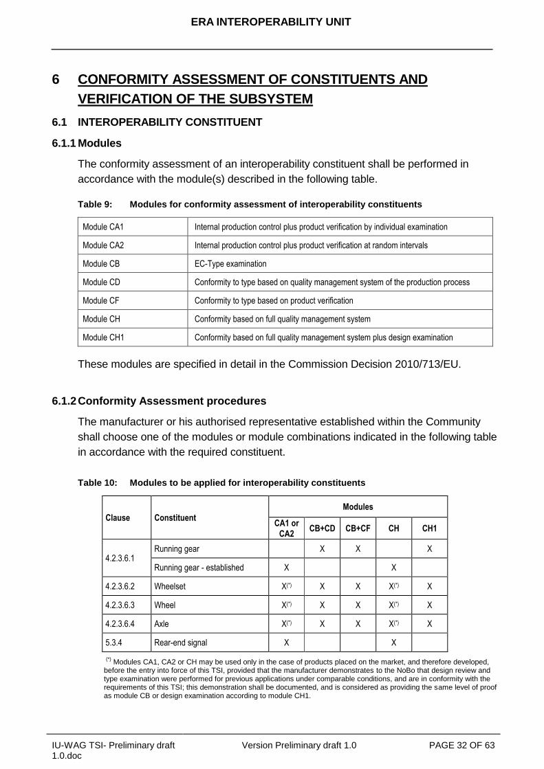
6.1.2 Conformity Assessment procedures
The manufacturer or his authorised representative established within the Community
shall choose one of the modules or module combinations indicated in the following table
in accordance with the required constituent.
Table 10: Modules to be applied for interoperability constituents
Clause Constituent
Modules
CA1 or CA2
CB+CD CB+CF CH CH1
4.2.3.6.1 Running gear X X X
Running gear - established X X
4.2.3.6.2 Wheelset X(*) X X X(*) X
4.2.3.6.3 Wheel X(*) X X X(*) X
4.2.3.6.4 Axle X(*) X X X(*) X
5.3.4 Rear-end signal X X
(*)
Modules CA1, CA2 or CH may be used only in the case of products placed on the market, and therefore developed, before the entry into force of this TSI, provided that the manufacturer demonstrates to the NoBo that design review and type examination were performed for previous applications under comparable conditions, and are in conformity with the requirements of this TSI; this demonstration shall be documented, and is considered as providing the same level of proof as module CB or design examination according to module CH1.
ERA INTEROPERABILITY UNIT
IU-WAG TSI- Preliminary draft 1.0.doc
Version Preliminary draft 1.0 PAGE 33 OF 63
Within the application of the chosen module or module combination the interoperability
constituent shall be assessed against the requirements mentioned in section 4.2 of this
TSI. If necessary, additional requirements concerning the assessment of particular
interoperability constituents are given in the following clauses.
6.1.2.1 Running gear
The demonstration of compliance for the running gear is set out in Appendix B.2 of this
TSI.
Units equipped with an established running gear as listed below are exempt from
running dynamic testing as long as they are operated within the established area of use:
Single axle running gear
- Double link suspension
- Niesky 2
- Suspension S 2000
Two-axle bogie running gear
- Y25 family
- Two-axle steering axle bogie
Three-axle bogies
- Three-axle bogie family with link suspension
The assessment of the bogie frame strength shall be based on clause 9.2 of EN
13749:2005.
6.1.2.2 Wheelset
The demonstration of compliance for the mechanical behaviour of the wheelset
assembly shall be based on clause 3.2.1 of EN13260:2009, which defines limit values
for the axial assembly force and the associated verification test.
A verification procedure shall exist to ensure at the assembly phase that no defects may
detrimentally affect safety due to any change in the mechanical characteristics of the
fitted parts of the axle.
6.1.2.3 Wheel
The mechanical characteristics of forged and rolled wheels shall be proven following the
procedure as specified in clause 7 of EN 13979-1:2003+A1:2009.
If the wheel is intended to be used with brake blocks acting on the wheel running
surface, the wheel shall be thermo mechanically proven by taking into account the
ERA INTEROPERABILITY UNIT
IU-WAG TSI- Preliminary draft 1.0.doc
Version Preliminary draft 1.0 PAGE 34 OF 63
maximum braking energy foreseen. A type test, as described in clause 6.2 of EN 13979-
1:2003+A1:2009 shall be performed in order to check that the lateral displacement of
the rim during braking and the residual stress are within the specified tolerance limits.
The decision criteria of residual stresses for forged and rolled wheels are set out in EN
13979-1:2003+A1:2009.
A verification procedure shall exist to ensure at the production phase that no defects
may detrimentally affect safety due to any change in the mechanical characteristics of
the wheels. The tensile strength of the material in the wheel, the hardness of the
running surface, the fracture toughness (only for tread braked wheels), resistance to
impact, the material characteristics and the material cleanliness shall be verified. The
verification procedure shall specify the batch sampling used for each characteristic to be
verified.
6.1.2.4 Axle
In addition to the requirement on the assembly above, the demonstration of compliance
for mechanical resistance and fatigue characteristics of the axle shall be based on
clauses 4, 5 and 6 of EN13103:2009.
The decision criteria for the permissible stress are specified in clause 7 of EN
13103:2009.
A verification procedure shall exist to ensure at the production phase that no defects
may detrimentally affect safety due to any change in the mechanical characteristics of
the axles. The tensile strength of the material in the axle, the resistance to impact, the
surface integrity, the material characteristics and the material cleanliness shall be
verified. The verification procedure shall specify the batch sampling used for each
characteristic to be verified.
6.1.3 Innovative solutions for Interoperability Constituents
If an innovative solution (as defined in clause 4.1 of this TSI) is proposed for an
interoperability constituent as defined in section 5.2 of this TSI, the manufacturer or his
authorised representative established within the Community shall state the deviations
from the relevant clause of this TSI and submit them to the European Commission for
analysis. In case the analysis results in a favourable opinion, the appropriate functional
and interface specifications as well as the assessment method which are necessary to
be included in the TSI in order to allow the use of this constituent will be developed.
The appropriate functional and interface specifications and the assessment methods so
produced shall be incorporated in the TSI by the revision process.

ERA INTEROPERABILITY UNIT
IU-WAG TSI- Preliminary draft 1.0.doc
Version Preliminary draft 1.0 PAGE 35 OF 63
By the notification of a decision of the Commission, taken in accordance with Article 29
of the Directive, the innovative solution may be permitted to be used before being
incorporated into the TSI by the revision process.
6.2 SUBSYSTEM
6.2.1 Modules
The EC verification of the subsystem “wagon” shall be performed in accordance with the
module(s) described in the following table.
Table 11: Modules for EC verification of subsystems
SB EC-Type Examination
SD EC verification based on quality management system of the production process
SF EC verification based on product verification
SH1 EC verification based on full quality management system plus design examination
These modules are specified in detail in the decision _____.
6.2.2 EC verification procedures
The applicant shall choose one of the following combinations of modules or module for
the EC verification of the subsystem.
(SB+SD) or
(SB+SF) or
(SH1).
Within the application of the chosen module or module combination the subsystem shall
be assessed against the requirements mentioned in section 4.2. If necessary, additional
requirements concerning the assessment of particular constituents are given in the
following clauses.
6.2.2.1 Strength of unit
The demonstration of conformity shall be based on chapters 6, 7 and 8 of EN 12663-
2:2010.
6.2.2.1 Safety against derailment running on twisted track
The demonstration of conformity shall be carried out either in accordance with
ERA INTEROPERABILITY UNIT
IU-WAG TSI- Preliminary draft 1.0.doc
Version Preliminary draft 1.0 PAGE 36 OF 63
the procedure defined in section 4.1 of EN 14363:2005 or
the method given in section 4.2 of prEN15839 by using the pre-calculation for
standardised solutions.
6.2.2.2 Running dynamic behaviour
The demonstration of compliance shall be carried out in accordance with chapter 5 of
EN 14363:2005.
As an alternative to performing on-track tests on two different rail inclinations, as set out
in paragraph 5.4.4.4 in EN 14363:2005 it is permitted to perform tests on only one rail
inclination if demonstrated that the tests cover the range of contact conditions defined in
Appendix B1.1.
When an on-track test with normal measuring method is required to be performed the
unit shall be assessed by the parameters set out in Appendix B.1.2 and B.1.3 of this
TSI.
Alternatively, under the conditions stated in section 9.3 of prEN 15827:2009, a
simulation may replace the above mentioned on-track tests.
The combination of the highest equivalent conicity and speed for which the unit meets
the stability criterion in clause 5 of EN 14363:2005 shall be recorded in the report.
The required test conditions for on-track tests, as set out in EN 14363:2005, are not
always fully achievable concerning
track geometric quality and
combinations of speed, curvature, cant deficiency.
In cases this is not fully achievable the demonstration of compliance is an open
point.
6.2.2.3 Axle box / bearings
The demonstration of compliance for mechanical resistance and fatigue characteristics
of the axle box and the rolling bearing shall be based on clause 6 of EN12082:2007 as
well as the measurement of the required temperature limits.
6.2.2.4 Thermal capacity
Calculations, simulations or tests shall approve, that the temperature of the brake block,
brake pad or brake disc does not exceed their thermal capacity. The following shall be
taken into account:
Concerning the emergency brake application: The critical combination of
ERA INTEROPERABILITY UNIT
IU-WAG TSI- Preliminary draft 1.0.doc
Version Preliminary draft 1.0 PAGE 37 OF 63
- speed and
- payload
considering straight and level track, minimum wind and dry rails.
Concerning the continuous brake application:
- The range up to the maximum braking power,
- the range up to the maximum speed and
- the corresponding brake application time.
Brake blocks, listed in the Technical Document 02 (ERA/TD/2009-02/INT) are
exempted from these calculations, simulations and tests under the defined conditions of
nominal wheel diameter, maximum axle load and brake configuration.
6.2.2.5 Environmental conditions
Steel materials are deemed to comply with the range indicated in clause 4.2.5 of this
TSI if specified for -20°C.
6.2.2.6 Fire safety
6.2.2.6.1 Barriers
Barriers shall be tested in accordance with EN1363-1 or with an equivalent method.
Steel sheets of at least 2mm thickness and aluminium sheets of at least 5mm thickness
are deemed to comply with the integrity requirements without testing.
6.2.2.6.2 Materials
For the following materials and components the fire safety requirements are fulfilled
without additional tests:
Metals and alloys with inorganic coatings (such as, but not limited to: galvanized
coating, anodic coating, chromate film, phosphate conversion coating).
Metals and alloys with an organic coating with a nominal thickness less than 0.3
mm (such as, but not limited to paints, plastic coating, asphaltic coating).
Metals and alloys with a combined inorganic and organic coating of which the
nominal thickness of the organic layer is less than 0.3 mm.
Glass, stoneware, ceramic and natural stone products,
Materials that meet the requirements of category C-s3,d2 or higher in accordance
with EN 13501-1:2007+A1:2009.
ERA INTEROPERABILITY UNIT
IU-WAG TSI- Preliminary draft 1.0.doc
Version Preliminary draft 1.0 PAGE 38 OF 63
6.2.4 Innovative solutions
If the subsystem “wagon” includes an innovative solution (as defined in clause 4.1 of
this TSI), the applicant shall state the deviations from the relevant clauses of the TSI,
and submit them to the Commission for analysis. In case the analysis results in a
favourable opinion, the appropriate functional and interface specifications as well as the
assessment methods which are necessary to be included in the TSI in order to allow
this solution will be developed.
The appropriate functional and interface specifications and the assessment methods so
produced shall then be incorporated in the TSI by the revision process.
By the notification of a decision of the Commission, taken in accordance with Article 29
of the Directive, the innovative solution may be permitted to be used before being
incorporated into the TSI by the revision process.
6.3 SUBSYSTEM CONTAINING INTEROPERABILITY CONSTITUENTS NOT HOLDING
AN EC DECLARATION
A Notified Body is permitted to issue an EC certificate of verification of a subsystem,
even if one or more of the interoperability constituents incorporated within the
subsystem are not covered by a relevant EC declaration of conformity in accordance
with this TSI (non-certified ICs), either in the case:
1. The constituent falls under the transition period as set out in Commission decision
related to this TSI or
2. the constituent was manufactured before the entry into force of this TSI and the
type of constituent has been
- used in a subsystem already approved and
- put in service in at least one Member State before the entry in force of this
TSI.
The EC verification of the subsystem shall be carried out by the Notified Body against
the requirements of chapter 4 using the corresponding requirements concerning
assessment in chapter 6 of this TSI together with chapter 7 of this TSI except specific
cases. For this verification the modules of the subsystem, set out in clause 6.2.2 of this
TSI, apply.
Neither an EC declaration of conformity nor an EC certificate of conformity shall be
drawn up for the interoperability constituents assessed in this manner.
The EC certificate of verification of the subsystem shall indicate clearly which
interoperability constituents have been assessed by the Notified Body as part of the
subsystem verification.
ERA INTEROPERABILITY UNIT
IU-WAG TSI- Preliminary draft 1.0.doc
Version Preliminary draft 1.0 PAGE 39 OF 63
6.4 PROJECT PHASES WHERE ASSESSMENT IS REQUIRED
The assessment shall cover the following two phases as identified by “X” in the table F.1
of Appendix F in this TSI. In particular, where a type test is identified the conditions and
requirements of section 4.2 of this TSI shall be considered.
Design and development phase:
- Design review and/or design examination
- Type test: test to verify the design, if and as defined in the section 4.2 of this
TSI.
Production phase:
- Routine test to verify the conformity of production. The entity in charge of the
assessment of the routine tests is determined according to the assessment
module chosen.
The Appendix F of this TSI is structured according to section 4.2 of this TSI. Where
relevant, a reference to the sub clauses of section 6.1 and 6.2 of this TSI is given.
6.5 INTEROPERABILITY CONSTITUENTS IN ACCORDANCE WITH DECISION
2006/861/EC
Where a constituent has been identified as an IC in the Decision 2006/861/EC,
assessed in accordance with the modules specified on Appendix Q to Decision
2006/861/EC and holding an EC declaration of conformity, its treatment under this TSI
is set out as follows:
In the case this constituent is not recognised as an IC in this TSI, neither the
certificate nor the declaration are valid for the EC verification procedure related to
this TSI.
The following ICs shall not require a new conformity assessment under this TSI
until the expiry of the corresponding certificate or declaration:
- Wheelset.
- Wheel.
- Axle.
ERA INTEROPERABILITY UNIT
IU-WAG TSI- Preliminary draft 1.0.doc
Version Preliminary draft 1.0 PAGE 40 OF 63
7 IMPLEMENTATION
7.1 AUTHORISATION FOR PLACING INTO SERVICE
Chapters 2 to 6 of this TSI and any specific provisions in section 7.3 apply in full to the
rolling stock coming within the scope set out in section 1.2 which will be placed into
service after this TSI enters into force.
7.1.1 Transitional period
During a transitional period, as defined in accordance with the Directive 2008/57/EC,
Article 5(3-f), the application of this TSI is not mandatory, under the following
conditions:
Projects at advanced stage of development, as described in the clause 7.1.1.1.
Contracts in course of performance, as described in the clause 7.1.1.2.
Rolling stock of an existing design, as described in clause 7.1.1.3.
Any rolling stock placed in service after the end date of the transitional period
described in this clause shall fully comply with this TSI without prejudice to Article 9 of
the Directive 2008/57/EC which allows Member States to request derogations under
the conditions set out in this Article.
7.1.1.1 Projects at advanced stage of development
This clause concerns rolling stock which is developed and produced under a project at
an advanced stage of development.
It shall be shown that the conditions set out in article 2(t) of the Directive 2008/57/EC
are met.
7.1.1.2 Contracts in course of performance
This clause concerns rolling stock which is developed and produced under a contract
which is signed before the entry into force of this TSI.
The applicant has to bring evidence of the date of signature of the original contract
applicable. The date of any addenda in the form of changes to an original contract
shall not be taken into account when defining the date of signature of the contract in
question.
ERA INTEROPERABILITY UNIT
IU-WAG TSI- Preliminary draft 1.0.doc
Version Preliminary draft 1.0 PAGE 41 OF 63
7.1.1.3 Rolling Stock of an existing design
This clause concerns rolling stock which is produced in accordance with a design
developed before the entry into force of this TSI.
The applicant has to prove that the newly built rolling stock will be produced in accordance
with a documented design that has already been used to produce a rolling stock which has
been authorised to be placed into service in a Member State before the date of entry into
force of this TSI.
Any modification to an existing design, which has an impact on the overall safety level
of the subsystem concerned, shall be assessed in accordance with the relevant parts
of this TSI by applying the procedure as set out in Article 20 of the Directive
2008/57/EC. The Member State shall thus examine the extent of the design change
and decide to what extent this TSI needs to be applied.
7.1.2 Mutual recognition of the first authorisation of placing in service
In accordance with article 23(1) of the Directive 2008/57/EC this TSI lays out the
conditions under which a unit shall not be subject to any additional authorisation for
placing in service. In the following these conditions are given:
...
...
...
...
...
7.2 SUBSTITUTION, RENEWAL AND UPGRADING
This TSI applies to
substitutions of constituents,
substitution of elements within a unit
and to renewal or upgrading of wagons
in accordance with the conditions laid down in Article 20 of the Directive.
Concerning the substitution of constituents the following categories have to be
considered.
Certified ICs: Constituents which are defined as IC in chapter 5 of this TSI and
which are holding a certificate of conformity or suitability for use.
Non ICs: Any constituent, which is not defined as IC in chapter 5 of this TSI.
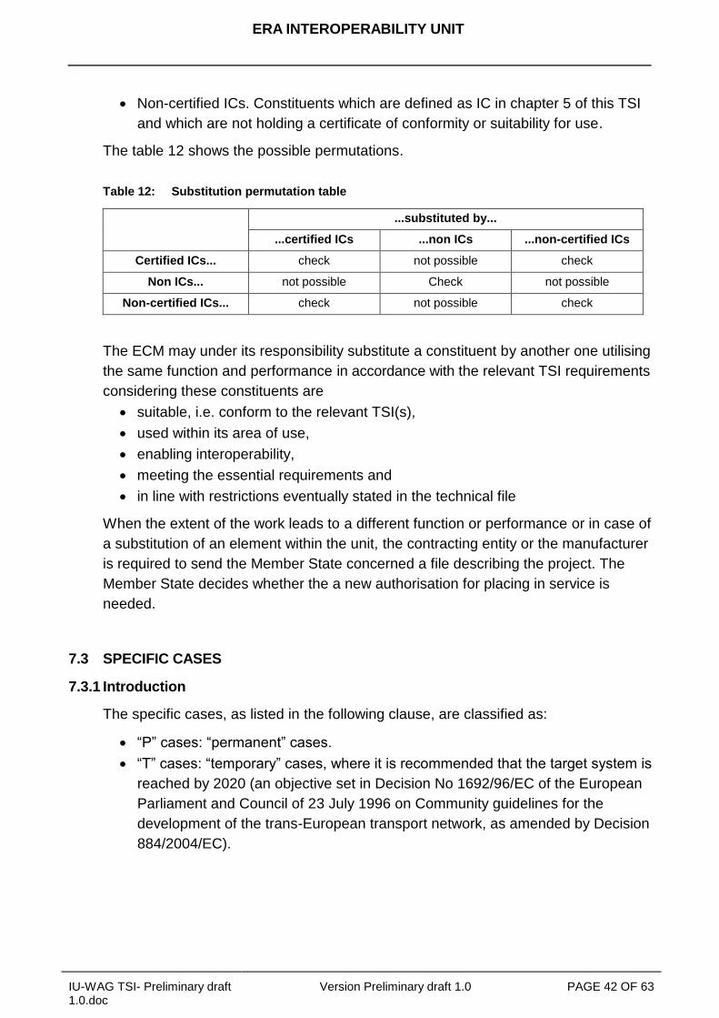
ERA INTEROPERABILITY UNIT
IU-WAG TSI- Preliminary draft 1.0.doc
Version Preliminary draft 1.0 PAGE 42 OF 63
Non-certified ICs. Constituents which are defined as IC in chapter 5 of this TSI
and which are not holding a certificate of conformity or suitability for use.
The table 12 shows the possible permutations.
Table 12: Substitution permutation table
...substituted by...
...certified ICs ...non ICs ...non-certified ICs
Certified ICs... check not possible check
Non ICs... not possible Check not possible
Non-certified ICs... check not possible check
The ECM may under its responsibility substitute a constituent by another one utilising
the same function and performance in accordance with the relevant TSI requirements
considering these constituents are
suitable, i.e. conform to the relevant TSI(s),
used within its area of use,
enabling interoperability,
meeting the essential requirements and
in line with restrictions eventually stated in the technical file
When the extent of the work leads to a different function or performance or in case of
a substitution of an element within the unit, the contracting entity or the manufacturer
is required to send the Member State concerned a file describing the project. The
Member State decides whether the a new authorisation for placing in service is
needed.
7.3 SPECIFIC CASES
7.3.1 Introduction
The specific cases, as listed in the following clause, are classified as:
“P” cases: “permanent” cases.
“T” cases: “temporary” cases, where it is recommended that the target system is
reached by 2020 (an objective set in Decision No 1692/96/EC of the European
Parliament and Council of 23 July 1996 on Community guidelines for the
development of the trans-European transport network, as amended by Decision
884/2004/EC).
ERA INTEROPERABILITY UNIT
IU-WAG TSI- Preliminary draft 1.0.doc
Version Preliminary draft 1.0 PAGE 43 OF 63
7.3.2 List of specific cases
List to be completed.
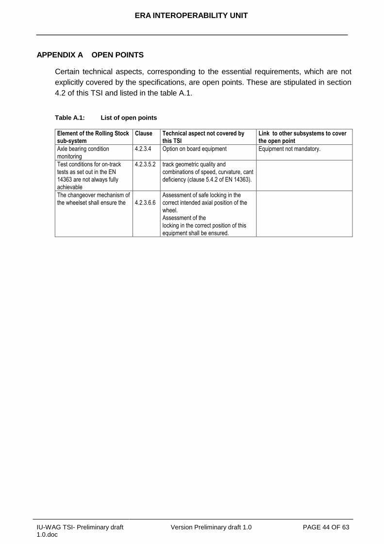
ERA INTEROPERABILITY UNIT
IU-WAG TSI- Preliminary draft 1.0.doc
Version Preliminary draft 1.0 PAGE 44 OF 63
APPENDIX A OPEN POINTS
Certain technical aspects, corresponding to the essential requirements, which are not
explicitly covered by the specifications, are open points. These are stipulated in section
4.2 of this TSI and listed in the table A.1.
Table A.1: List of open points
Element of the Rolling Stock sub-system
Clause Technical aspect not covered by this TSI
Link to other subsystems to cover the open point
Axle bearing condition
monitoring
4.2.3.4 Option on board equipment Equipment not mandatory.
Test conditions for on-track
tests as set out in the EN
14363 are not always fully
achievable
4.2.3.5.2 track geometric quality and
combinations of speed, curvature, cant
deficiency (clause 5.4.2 of EN 14363).
The changeover mechanism of
the wheelset shall ensure the
4.2.3.6.6
Assessment of safe locking in the
correct intended axial position of the
wheel.
Assessment of the
locking in the correct position of this
equipment shall be ensured.

ERA INTEROPERABILITY UNIT
IU-WAG TSI- Preliminary draft 1.0.doc
Version Preliminary draft 1.0 PAGE 45 OF 63
APPENDIX B SPECIFIC PROCEDURES FOR RUNNING DYNAMICS
B.1 Specific assessment concerning running dynamic testing following EN 14363
B.1.1Conditions for testing on one rail inclination
The parameter equivalent conicity tan γe for tangent track and large radius curves
shall be distributed so that tan γe = 0,2 ± 0,05 occurs in a range of the amplitude
(y) of the wheelsets lateral displacement between +/-2 and +/-4 mm for a minimum
of 50% of track sections.
The instability criterion in EN14363:2005 shall be assessed for low-frequency body
motions on at least two track sections with equivalent conicities less than 0.05
(mean value over the track sections).
The instability criterion in EN14363:2005 shall be assessed on at least two track
sections with equivalent conicities in accordance with the table B.1.
Table B.1: Conditions for contact conditions in relation to on-track testing
Maximum vehicle speed Equivalent conicity
60 km/h < V ≤ 140 km/h ≥0,50
140 km/h < V ≤ 200 km/h ≥0,40
200 km/h < V ≤ 230 km/h ≥0,35
230 km/h < V ≤ 250 km/h ≥0,30
B.1.2Limit values for running safety
The limit values for running safety specified in clause 5.3.2.2 of EN 14363:2005 and for
axle loads above 22.5 t in clause 5.3.2.2 of EN 15687:2010 shall be met and verified.
When the quotient of guiding force and wheel force (Y/Q) limit is exceeded, it is allowed
to recalculate the Y/Q estimated maximum value in accordance with the following
process:
create an alternative test zone made up of all track sections with
300 m ≤ R ≤ 500 m,
for the statistical processing per section, use xi (97,5%) instead of xi (99,85%),
for statistical processing per zone, replace k = 3 (when using one-dimensional
method) or Student coefficient t (N - 2; 99%) (when using two-dimensional
method) by Student coefficient t (N-2; 95%).
Both results (before and after recalculation) shall be reported.
ERA INTEROPERABILITY UNIT
IU-WAG TSI- Preliminary draft 1.0.doc
Version Preliminary draft 1.0 PAGE 46 OF 63
B.1.3Track loading limit values
The limit values for track loading specified in EN 14363:2005 clause 5.3.2.3 and for
loads above 22.5 t in EN 15687:2010 clause 5.3.2.2 shall be met and verified when so
required by the methodology of EN 14363:2005.
The quasi-static guiding force Yqst limit value shall be evaluated for curve radii
250≤R<400m.
The limit value shall be : (Yqst)lim = (30 + 10500/Rm) kN, where
Rm = mean radius of the track sections retained for the evaluation.
When this limit value is exceeded due to high friction conditions, it is permitted to
recalculate the estimated value of Yqst on the zone after replacing the individual (Yqst)i
values on the track sections "i" where (Y/Q)ir (mean value of Y/Q ratio on the inner rail
over the section) exceeds 0,40 by: (Yqst)i - 50[(Y/Q)ir - 0,4]. Both results (before and
after recalculation) shall be reported.
The values of the Yqst, Qqst and mean curve radius (before and after recalculation)
shall be recorded in the test report.
In case the Yqst value exceeds the limit value expressed above, the operational
performance of the unit (e.g. maximum speed) may be limited by the infrastructure,
considering track characteristics (e.g. curve radius, cant, rail height).
B.2 Qualification of running gear
Following successful testing the acceptable parameter variation range is given by the
range between the nominal tested parameters extended as illustrated in figure B.1.
It is permitted to perform only one test and by doing so only validating the running gear
for a limited range.
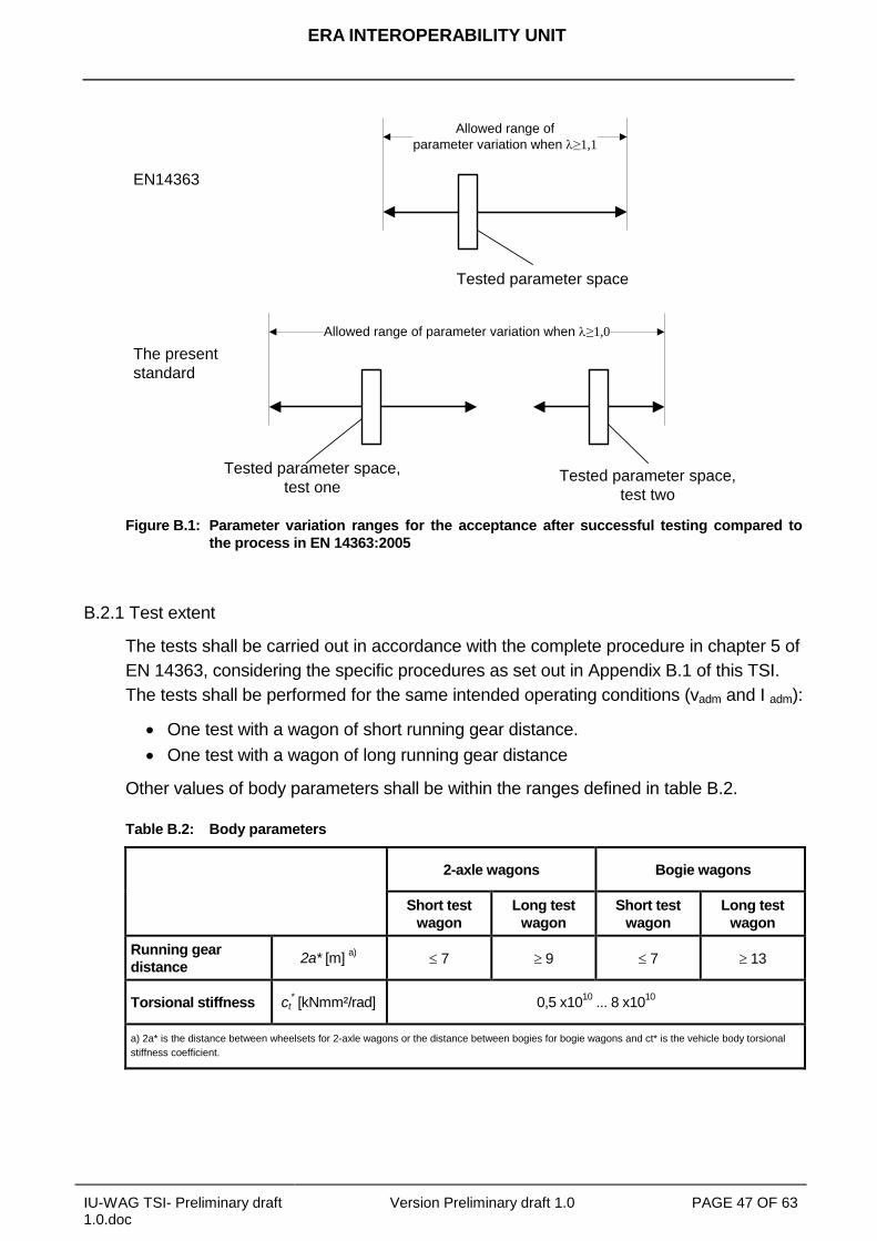
ERA INTEROPERABILITY UNIT
IU-WAG TSI- Preliminary draft 1.0.doc
Version Preliminary draft 1.0 PAGE 47 OF 63
Allowed range of
parameter variation when l≥1,1
EN14363
Tested parameter space
Tested parameter space,
test oneTested parameter space,
test two
Allowed range of parameter variation when l≥1,0
The present
standard
Figure B.1: Parameter variation ranges for the acceptance after successful testing compared to
the process in EN 14363:2005
B.2.1 Test extent
The tests shall be carried out in accordance with the complete procedure in chapter 5 of
EN 14363, considering the specific procedures as set out in Appendix B.1 of this TSI.
The tests shall be performed for the same intended operating conditions (vadm and I adm):
One test with a wagon of short running gear distance.
One test with a wagon of long running gear distance
Other values of body parameters shall be within the ranges defined in table B.2.
Table B.2: Body parameters
2-axle wagons Bogie wagons
Short test
wagon
Long test
wagon
Short test
wagon
Long test
wagon
Running gear
distance 2a* [m]
a) 7 9 7 13
Torsional stiffness ct* [kNmm²/rad] 0,5 x10
10 ... 8 x10
10
a) 2a* is the distance between wheelsets for 2-axle wagons or the distance between bogies for bogie wagons and ct* is the vehicle body torsional
stiffness coefficient.
ERA INTEROPERABILITY UNIT
IU-WAG TSI- Preliminary draft 1.0.doc
Version Preliminary draft 1.0 PAGE 48 OF 63
Note 1: For the purposes of assessment of running behaviour a typical loading condition
must be tested. It is not necessary to test the worst possible density of the load using
the maximum axle load and filling the whole loading gauge.
In addition, 2 axle wagons for speeds 100 km/h shall be tested in loaded condition also
in sections of test zone 2 with clearances given by a gauge of 1450 mm in combination
with wheelsets having distances between active faces at the minimum operation limit.
Note 2: It is desirable to perform such tests based on measurements of lateral
acceleration, if it can be shown that a relationship exists between accelerations and the
sum of the guiding forces and a related limit value was established.
Note 3: This requirement is intended to be shifted to the test conditions in EN 14363.
B.2.2 Range of running gear parameters for dispensation from on-track tests
Following successful testing in accordance with Appendix B.2.1 the acceptable
parameter variation range for dispensation from on-track tests is given by the range
between the nominal tested parameters extended as illustrated in figure B.1 and
specified in tables B.3 and B.4.
All parameters given in these tables are nominal values. The upper limit of the
acceptable range depends on the maximum tested value of the respective parameter,
the lower limit on the minimum tested value.
In case of extension of the already applicable parameter range of a running gear, new
tests shall be performed with parameters outside the previously tested range.
Table B.3: Accepted parameters for a single axle running gear which was tested successful in accordance with Appendix B.2.1 of this TSI
Nominal parameter Minimum Maximum
Maximum axle load P - Ptested
Vertical eigenfrequency vz 0.9 vz in load range 1.12 vz in load range
Vertical damping Tested characteristics Tested characteristics
Lateral suspension characteristics
Tested characteristics Tested characteristics
Wheel diameter D Diameter of tested application Dnom –90 mm
Diameter of tested application Dnom +90 mm
ERA INTEROPERABILITY UNIT
IU-WAG TSI- Preliminary draft 1.0.doc
Version Preliminary draft 1.0 PAGE 49 OF 63
Table B.4: Accepted parameters for a bogie which was tested successful in accordance with Appendix B.2.1 of this TSI
Nominal parameter Minimum Maximum
Maximum axle load Pmax - 1,05 . Pmax,tested
Bogie axle distance (between outer axles of the bogie) 2a
+ 2a
+tested 2a
+tested + 0,2 m
Vertical eigenfrequency (see Appendix C) z 0,90
. z,tested in load range 1,12
. z,tested in load range
Vertical Damping Tested characteristics Tested characteristics
Axle guiding longitudinal Tested characteristics Tested characteristics
Axle guiding lateral Tested characteristics Tested characteristics
Lateral secondary susp. characteristics
Tested characteristics Tested characteristics
Yaw resistance of bogiea) M*z 0,80
. M
*z,tested 1,20
. M
*z,tested
Moment of inertia of whole bogie (around z-axis)
I*zz 0 1,10 I
*zz,tested
Wheel diameter D Dtested –90 mm Dtested +90 mm
Nominal height of centre pivot
hcp hcP,tested – 150 mm hcP,tested + 50 mm
a) for a friction based yaw resistance torque measured at two specified loads typical for empty and loaded condition. For other
systems, appropriate parameters must be used to control stability and safety against derailment in empty condition and
maximum guiding force in loaded conditions.
B.2.3 Range of vehicle body parameters for dispensation from on-track tests
Following successful testing according to Appendix B.2.1of this TSI the acceptable
parameter variation range for a dispensation from on-track tests is given by the range
between the nominal tested parameters and extended where applicable as specified in
table B.5. All parameters given in this table are nominal values. The upper limit of the
acceptable range depends on the maximum tested value of the respective parameter,
the lower limit on the minimum tested value.
To extend the applicable vehicle parameter range of a standardised running gear, test
results of a third tested vehicle outside the previously tested range shall be used.

ERA INTEROPERABILITY UNIT
IU-WAG TSI- Preliminary draft 1.0.doc
Version Preliminary draft 1.0 PAGE 50 OF 63
Table B.5: Accepted parameters for vehicles (included articulated wagons and permanently coupled units) equipped with a running gear which was tested successfully according to Appendix B.2.1 of this TSI
Nominal parameter Minimum Maximum
Distance between wheelsets (non bogie vehicles)
2a* Lowest value of 6 m and 2a
*tested
Highest value of 10 m and 2a
*tested
Distance between bogies (bogie vehicles)
2a*
Lowest value of 6,5 m and 2a
*tested
2a*tested + 3m
Centre of gravity height of empty wagon
hcg 0 1,2 . hcg,empty,tested, max
Coefficient of height of centre of gravity - loaded vehicle
a)
0 loaded,tested,max x 0,8(l'-1)
with l' – factor for track loading parameters (see 3.10)
Torsional stiffness per car body
ct* > 0,5 10
10 kNmm²/rad '-
Mean axle load of the tare unit (non-bogie wagon)
Pmean,tare Smallest value of 5,75 t and Pmean,tare,tested
-
Mean axle load of the tare unit (bogie wagon)
Pmean,tare Smallest value of 4 t and Pmean,tare,tested
-
Maximum axle load P - 1,05 . Ptested
Mass distrib. coefficient (empty and loaded vehicle)
0 1,2 . tested
a) for evaluation of admissible cant deficiency Iadm of 130 mm for axle loads ≤ 225 kN and 100 mm for axle loads> 225 kN
and up to 250 kN.
ERA INTEROPERABILITY UNIT
IU-WAG TSI- Preliminary draft 1.0.doc
Version Preliminary draft 1.0 PAGE 51 OF 63
APPENDIX C ADDITIONAL OPTIONAL CONDITIONS FOR UNITS USED UNDER
CERTAIN OPERATIVE REGIMES
In addition to the assessment against the core TSI requirements an applicant may ask the
Notified Body for the assessment of conformity with the requirements set out in this
Appendix. A unit which fulfils all the following conditions may be marked ???. A unit in
accordance with all conditions of this Appendix except for those set out in C.3, C.6 and C.7
may be marked ???.
C.1 End coupling
The manual coupling system shall comply with the following requirements:
the screw coupling system excluding the draw hook shall comply with the
requirements of EN15566:2009 except clause 4.4 related to freight wagons,
the draw hook shall comply to EN15566:2009 except clause 4.4 related to freight
wagons and except the dimension “a” in Annex A Figure A.1.,
the buffer shall comply with the requirements of the part EN15551:2009
related to freight wagons.
There shall be no fixed parts within 40 mm of a vertical plane placed at the end
of the fully compressed buffers.
The space for shunting staff operation shall be in accordance to prEN 16116-2,
clause 6.2.
Where a combined automatic and screw coupler is fitted, it is permissible for the
auto coupler head to infringe the Berne rectangle on the left hand side when it is
stowed and the screw coupler is in use. In this case marking EN 15 877-1 Figure
78 is mandatory.
the buffing centre line shall be located at a height between 940 and 1065 mm
above rail level in all loading and wear conditions.
the hook shall be located at a height between 920 and 1045 mm above rail level
in all loading and wear conditions.
The clearance for draw hook shall be in accordance with prEN16116-2:20__, clause 6.3.2.
Interaction of buffers and draw gear
The characteristics of the buffers and draw gear shall be designed in order to
enable the safe transit of curves in the track with a radius of 150 m. Two units
with bogies coupled on straight track with touching buffers shall generate
compressive forces not higher than 250 kN on a 150 m radius curve. There is no
requirement specified for two axle wagons.
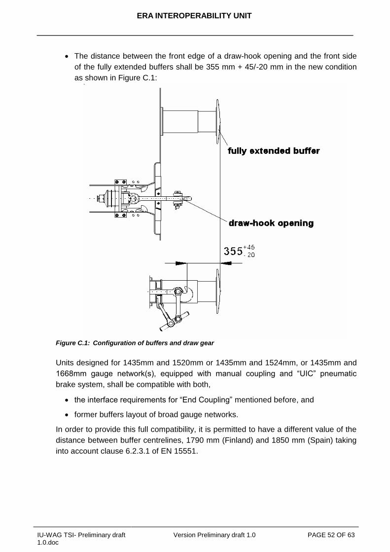
ERA INTEROPERABILITY UNIT
IU-WAG TSI- Preliminary draft 1.0.doc
Version Preliminary draft 1.0 PAGE 52 OF 63
The distance between the front edge of a draw-hook opening and the front side
of the fully extended buffers shall be 355 mm + 45/-20 mm in the new condition
as shown in Figure C.1:
Figure C.1: Configuration of buffers and draw gear
Units designed for 1435mm and 1520mm or 1435mm and 1524mm, or 1435mm and
1668mm gauge network(s), equipped with manual coupling and “UIC” pneumatic
brake system, shall be compatible with both,
the interface requirements for “End Coupling” mentioned before, and
former buffers layout of broad gauge networks.
In order to provide this full compatibility, it is permitted to have a different value of the
distance between buffer centrelines, 1790 mm (Finland) and 1850 mm (Spain) taking
into account clause 6.2.3.1 of EN 15551.
ERA INTEROPERABILITY UNIT
IU-WAG TSI- Preliminary draft 1.0.doc
Version Preliminary draft 1.0 PAGE 53 OF 63
C.2 Footsteps and handrails
Concerning Footsteps and handrails sections 4.2, 4.3, 5 and 6.2.2 of prEN 16116-
2:20__, shall apply.
C.3 Strength of main vehicle structure and equipment
In addition to the requirements of 4.2.2.2 of this TSI the unit shall be classified in
Category F I in accordance with clause 5.1 of EN 12663-2:2010 with the following
exception: units designed to carry motor vehicles or combined transport units without
long stroke shock absorbers the Category F-II may be used.The requirements
concerning the buffing tests in clause 8.2.5.1 of EN 12663-2:2010 applies.
C.4 Lifting and jacking
The unit shall comply with the following diagram on the free space under the re-railing
places for re-railing:
Figure C.2: Free spaces under rerailing places
C.5 Marking of units
Markings of prEN 15877-1:2010 are required if applicable. The following are always
applicable:
4.5.2 Gauge marking
4.5.3 Vehicle Tare Weight
4.5.4 Vehicle load table
ERA INTEROPERABILITY UNIT
IU-WAG TSI- Preliminary draft 1.0.doc
Version Preliminary draft 1.0 PAGE 54 OF 63
4.5.5 Sign for length over buffers
4.5.12 Table of Maintenance dates
4.5.14 Lifting and re-railing signs
4.5.23 Distances between end axles and bogie centres
4.5.__ Brake weight
C.6 Gauging
The reference contour with which the unit complies with shall be G1 and GI1
determined as defined in 4.2.3.1 of this TSI.
C.7 Unit characteristics for the compatibility with train detection systems
The unit shall be compatible with the train detection systems based on track circuits
and based on axle counters as specified in clauses 4.2.3.3.1and 4.2.3.3.2.
C.8 Longitudinal compressive forces
The verification of safe running under longitudinal compressive forces shall be based
on EN 15839:2011.
C.9 Brake
The brake system shall be compatible with vehicles equipped with UIC approved
brake systems. The brake system of a unit is compatible with the UIC brake system if
it fulfils the following requirements:
The unit shall be equipped with a pneumatic brake pipe with an inner diameter of
32 mm.
Brake modes have different brake application and release times and specific
brake weight percentage.
Every unit shall be fitted with a brake system having at least brake modes G and
P.
The brake modes G and P shall be assessed according to
EN15355:2008+A1:2010 and EN 15611:2008+A1:2010 or UIC 540:2006.
The minimum braking performance for brake-modes G and P shall be in
accordance with table C.1:
ERA INTEROPERABILITY UNIT
IU-WAG TSI- Preliminary draft 1.0.doc
Version Preliminary draft 1.0 PAGE 55 OF 63
Table C.1: Minimum braking performance for brake modes G and P B
rakin
g m
od
e
un
it t
yp
e
Co
mm
an
d E
qu
ipm
en
t
Lo
ad
sta
tus
Requirement for running speed at 100km/h Requirement for running speed at 120km/h
Maximum braking
distance
Minimum braking
distance
Maximum braking
distance
Minimum braking
distance
Bra
kin
g m
ode “
P”
All
All
Em
pty
Smax = 480m λmin = 100%
(1)
amin=0,91m/s2 (1)
Smin = 390m, λmax=125%, (130%)*, amax= 1,15m/s
2
Smax = 700m λmin = 100% amin = 0,88m/s
2
Smin =580m, λmax= 125%, (130%)*, amax=1,08m/s
2
„‟S1‟‟(2
)
Changeover
(9)
Inte
r-m
edia
te
Smax = 810m λmin = 55% amin = 0,51m/s
2
Smin= 390m, λmax= 125%, amax =1,15m/s
2
Loaded
Smax = 700m λmin = 65 % amin = 0,60m/s
2
Smin = Max [(S = 480m, λmax=100%, amax= 0,91m/s
2), (S obtained
with a mean retardation force of 16,5 kN per axle)]
(5).
“S2”(3
)
Varia
ble
lo
ad
Rela
y (1
0)
Loaded
Smax = 700m λmin = 65 % amin = 0,60m/s
2
Smin = Max [(S = 480m, λmax=100 %, amax = 0,91m/s
2), (S obtained
with a mean retardation force of 16,5 kN per axle)]
(6).
“SS
”(4)
Varia
ble
lo
ad
Rela
y (1
0)
Loaded
(18t
per
axle
for
bra
ke b
locks)
Smax
(8) = Max [S = 700m, λmax=100%,
amax = 0,88m/s2), (S obtained with a mean
retardation force of 16kN per axle)] (7)
.
Bra
kin
g m
ode “
G”
There shall be no separate assessment of the braking performance of units in position G. A unit‟s braked weight in position G is the result of the braked weight in position P (see UIC 544-1)
*only for two stage load brake (changeover command) and P10 (cast iron blocks with 10 ‰ phosphor)- or LL-brake blocks
(1) “a” = ((Speed (Km/h))/3,6)^2)/(2x(S-((Te)x(Speed (Km/h)/3,6)))), with Te=2sec. Distance calculation EN 14531-1:2005 section
5.11
(2) a unit “S1” is a unit with empty/load device. Maximum load per axle is 22,5 t.
(3) a unit “S2” is a unit with a variable load relay. Maximum load per axle is 22,5 t.
ERA INTEROPERABILITY UNIT
IU-WAG TSI- Preliminary draft 1.0.doc
Version Preliminary draft 1.0 PAGE 56 OF 63
(4) a unit “SS” shall be equipped with a variable load relay. Maximum load per axle is 22,5 t.
(5) The maximum mean retardation force admitted (for running speed at 100km/h) is 18x0,91 = 16,5 kN/axle. This value comes
from the maximum braking energy input permitted on a clasp braked wheel with a nominal new diameter in the range of [920
mm; 1 000 mm] during braking (the brake weight shall be limited to 18 tonnes/axle).
(6) The maximum mean retardation force admitted (for running speed at 100km/h) is 18x0,91 = 16,5 kN/axle. This value comes
from the maximum braking energy input permitted on a clasp braked wheel with a nominal new diameter in the range of [920
mm; 1 000 mm] during braking (the brake weight shall be limited to 18 tonnes/axle). Usually a unit, with V max = 100 km/h and
fitted with a variable relay is designed to obtain λ = 100% up to 14.5 t/axle.
(7) The maximum mean retardation force admitted (for running speed at 120km/h) is 18x0,88 = 16 kN/axle. This value comes
from the maximum braking energy input permitted on a clasp braked wheel with a nominal new diameter in the range of [920
mm; 1 000 mm] during braking (the brake weight shall be limited to 18 tonnes). The mass/axle is limited to 20 t/axle and the
corresponding λ is 90%. If it is required λ > 100% with mass/axle > 18 t then it is necessary to consider another kind of brake.
(8) λ must not exceed 125%, considering for brake only on wheels (brake blocks), the maximum mean retardation force admitted
of 16 kN/axle (for running speed at 120km/h).
(9) Changeover according to EN 15624:2008+A1:2010.
(10) Variable load relay according to EN 15611:2008+A1:2010 in combination with variable load sensing device according to EN
15625:2008+A1:2010.
If a unit is equipped with a brake system having in addition further brake modes
the assessment procedure as described in clause 4.2.4.3.2.1 shall be carried out
for these additional brake modes. The brake application time of the P brake
mode according to EN15355:2008+A1:2010 and EN 15611:2008+A1:2010 or
UIC 540:2006 are also valid for further brake modes.
The energy storage has to be designed in such way that after a brake
application with the maximum brake cylinder pressure and the maximum unit
specific brake cylinder stroke at any load state the pressure in the auxiliary
reservoir must be at least 0,3 bar more than the brake cylinder pressure without
the addition of any further energy.
The pneumatic energy of the brake system shall not be used for other
applications different than those related to braking purposes.
The pneumatic half coupling:
- The interface shall be according to UIC 541-1:2003 Appendix D and E or
FprEN 15807:2008
- The opening of the automatic air brake coupling head shall face the left
when looking at the end of the vehicle.
- The opening of the main reservoir coupling head shall face the right when
looking at the end of the unit.
- The end cocks shall be in accordance with EN 14601:2005+A1:2010.
C.10 Parking brake
If a unit is equipped with a parking brake the location shall be:
On both sides of the unit if it is operated from the ground or
On a platform, that can be accessed from both sides of the unit
ERA INTEROPERABILITY UNIT
IU-WAG TSI- Preliminary draft 1.0.doc
Version Preliminary draft 1.0 PAGE 57 OF 63
C.11 Environmental conditions
The following requirements are deemed to comply with the range indicated in
clause 4.2.5.
Air reservoir shall be designed for the temperature range of -40°C to +100°C.
Brake cylinders and brake couplings shall be designed for the temperature range
of -40°C to +70°C.
Hoses for air brakes and air supply shall be specified for the temperatures range
-40°C to +70°C.
The grease for the lubrication of roller bearing shall be specified for ambient
temperatures down to -20°C.
C.12 Welding
For welding EN 15085-1-5:2007 apply.
C.13 Track Gauge
The unit shall be compatible with the 1435 mm track gauge.
C.14 Brake thermal capacity
The brake system shall resist a thermal load equivalent to a braking power of 45 kW
per wheel for 34 minutes at 70km/h in addition to the requirements set out in clause
4.2.4.3.3.
Brake blocks, listed in the Technical Document 02 (ERA/TD/2009-02/INT) are
exempted from these simulations and tests for the nominal wheel diameter D=920mm,
the mass per wheel 11,25 t and for the appropriate block configuration used in the unit.
If the design of the unit complies with the following “standard” conditions
nominal wheel diameter D between 680 mm and 920 mm
maximum design speed 120 km/h
brake block force between 5 and 38 kN for K brake block and between 12 and
100 kN for LL brake blocks for single sided brake block configuration.
brake block force between 2.5 and 19 kN for K brake block and between 6 and
50 kN for LL brake blocks for double side brake block configuration.
braked mass per wheel between 2.5 and 11.25 t
the specific ratio between the max. brake energy and the rim volume of the
wheel of the unit does not exceed the specific ratio or the brake block listed in
ERA INTEROPERABILITY UNIT
IU-WAG TSI- Preliminary draft 1.0.doc
Version Preliminary draft 1.0 PAGE 58 OF 63
the technical Document 02 (ERA/TD/2009-02/INT) for the nominal wheel
diameter D 920mm and the mass per wheel 11,25 t.
and
the brake block is listed in the Technical Document 02 (ERA/TD/2009-02/INT) for
the nominal wheel diameter D 920mm, the mass per wheel 11,25 t and the
appropriate block configuration used in the unit
and
the wheel is according to 6.1.2.3 with the requirements of C.15
the requirements concerning thermal capacity are fulfilled.
If the design of the unit does not meet the “standard” conditions above the wheel shall
be tested according to 6.1.2.3 with the requirements of C.15 and the brake block shall
be tested by a test bench program defined in accordance with the test bench
programs of UIC 541-4:2010 taking into account the maximum brake energy.
C.15 Wheel
The wheels shall be in accordance with EN 13262: 2004+A1:2008 and EN 13979-
1:2003 +A1:2009. The thermal mechanical type test required in 6.1.2.3 shall be carried
out in accordance with table C.2 when the brake system is acting directly on the wheel
tread.
Table C.2:
Wheel diameter range [mm] 1000 - 920 920 - 840 840 - 760 760 - 680
Standard power value 50 kW 50 kW 42,5 kW 38 kW
Application time 45 min 45 min 45 min 45 min
Running speed 60 km/h 60 km/h 60 km/h 60 km/h
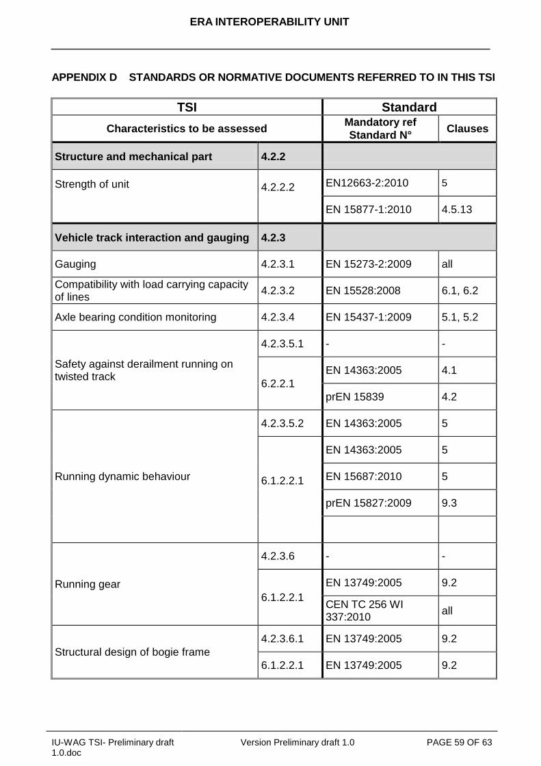
ERA INTEROPERABILITY UNIT
IU-WAG TSI- Preliminary draft 1.0.doc
Version Preliminary draft 1.0 PAGE 59 OF 63
APPENDIX D STANDARDS OR NORMATIVE DOCUMENTS REFERRED TO IN THIS TSI
TSI Standard
Characteristics to be assessed Mandatory ref
Standard N° Clauses
Structure and mechanical part 4.2.2
Strength of unit
4.2.2.2
4.2.2.2
EN12663-2:2010 5
EN 15877-1:2010 4.5.13
Vehicle track interaction and gauging 4.2.3
Gauging 4.2.3.1 EN 15273-2:2009 all
Compatibility with load carrying capacity of lines
4.2.3.2 EN 15528:2008 6.1, 6.2
Axle bearing condition monitoring 4.2.3.4 EN 15437-1:2009 5.1, 5.2
Safety against derailment running on twisted track
4.2.3.5.1 - -
6.2.2.1
EN 14363:2005 4.1
prEN 15839 4.2
Running dynamic behaviour
4.2.3.5.2 EN 14363:2005 5
6.1.2.2.1
6.1.2.2.1
EN 14363:2005 5
EN 15687:2010 5
prEN 15827:2009 9.3
Running gear
4.2.3.6 - -
6.1.2.2.1
EN 13749:2005 9.2
CEN TC 256 WI 337:2010
all
Structural design of bogie frame
4.2.3.6.1 EN 13749:2005 9.2
6.1.2.2.1 EN 13749:2005 9.2
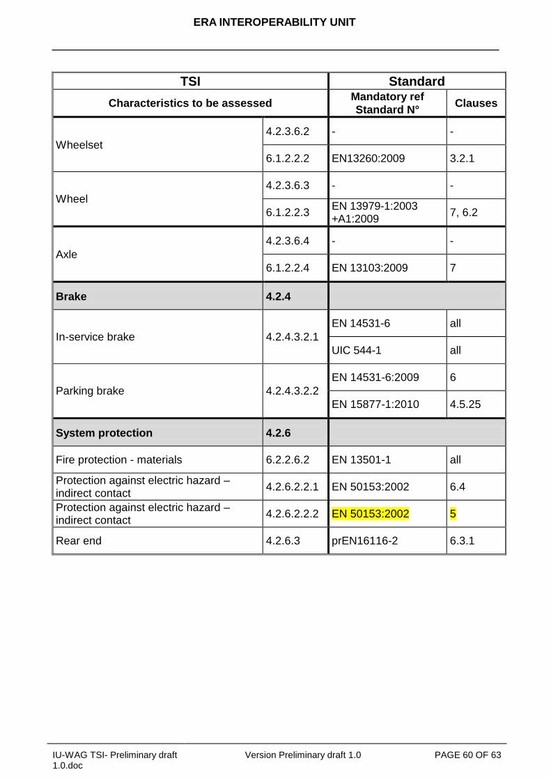
ERA INTEROPERABILITY UNIT
IU-WAG TSI- Preliminary draft 1.0.doc
Version Preliminary draft 1.0 PAGE 60 OF 63
TSI Standard
Characteristics to be assessed Mandatory ref
Standard N° Clauses
Wheelset
4.2.3.6.2 - -
6.1.2.2.2 EN13260:2009 3.2.1
Wheel
4.2.3.6.3 - -
6.1.2.2.3 EN 13979-1:2003 +A1:2009
7, 6.2
Axle
4.2.3.6.4 - -
6.1.2.2.4 EN 13103:2009 7
Brake 4.2.4
In-service brake 4.2.4.3.2.1
EN 14531-6 all
UIC 544-1 all
Parking brake 4.2.4.3.2.2
EN 14531-6:2009 6
EN 15877-1:2010 4.5.25
System protection 4.2.6
Fire protection - materials 6.2.2.6.2 EN 13501-1 all
Protection against electric hazard – indirect contact
4.2.6.2.2.1 EN 50153:2002 6.4
Protection against electric hazard – indirect contact
4.2.6.2.2.2 EN 50153:2002 5
Rear end 4.2.6.3 prEN16116-2 6.3.1
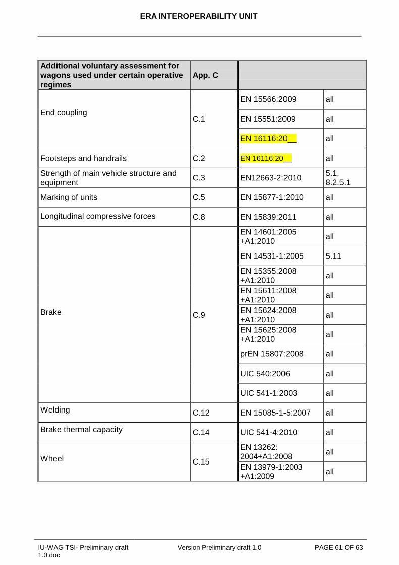
ERA INTEROPERABILITY UNIT
IU-WAG TSI- Preliminary draft 1.0.doc
Version Preliminary draft 1.0 PAGE 61 OF 63
Additional voluntary assessment for
wagons used under certain operative
regimes
App. C
End coupling
C.1
EN 15566:2009 all
EN 15551:2009 all
EN 16116:20__ all
Footsteps and handrails C.2 EN 16116:20__ all
Strength of main vehicle structure and equipment
C.3 EN12663-2:2010 5.1, 8.2.5.1
Marking of units C.5 EN 15877-1:2010 all
Longitudinal compressive forces C.8 EN 15839:2011 all
Brake C.9
EN 14601:2005 +A1:2010
all
EN 14531-1:2005 5.11
EN 15355:2008 +A1:2010
all
EN 15611:2008 +A1:2010
all
EN 15624:2008 +A1:2010
all
EN 15625:2008 +A1:2010
all
prEN 15807:2008 all
UIC 540:2006 all
UIC 541-1:2003 all
Welding C.12 EN 15085-1-5:2007 all
Brake thermal capacity C.14 UIC 541-4:2010 all
Wheel C.15
EN 13262: 2004+A1:2008
all
EN 13979-1:2003 +A1:2009
all
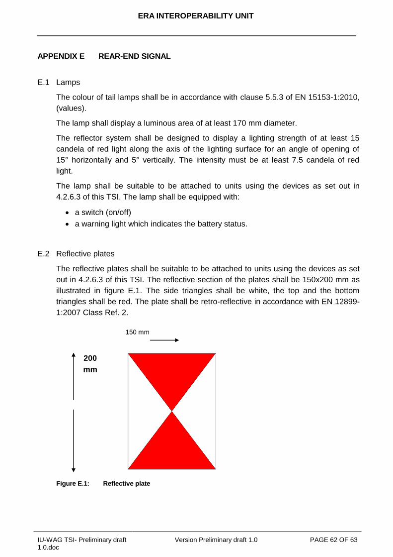
ERA INTEROPERABILITY UNIT
IU-WAG TSI- Preliminary draft 1.0.doc
Version Preliminary draft 1.0 PAGE 62 OF 63
APPENDIX E REAR-END SIGNAL
E.1 Lamps
The colour of tail lamps shall be in accordance with clause 5.5.3 of EN 15153-1:2010,
(values).
The lamp shall display a luminous area of at least 170 mm diameter.
The reflector system shall be designed to display a lighting strength of at least 15
candela of red light along the axis of the lighting surface for an angle of opening of
15° horizontally and 5° vertically. The intensity must be at least 7.5 candela of red
light.
The lamp shall be suitable to be attached to units using the devices as set out in
4.2.6.3 of this TSI. The lamp shall be equipped with:
a switch (on/off)
a warning light which indicates the battery status.
E.2 Reflective plates
The reflective plates shall be suitable to be attached to units using the devices as set
out in 4.2.6.3 of this TSI. The reflective section of the plates shall be 150x200 mm as
illustrated in figure E.1. The side triangles shall be white, the top and the bottom
triangles shall be red. The plate shall be retro-reflective in accordance with EN 12899-
1:2007 Class Ref. 2.
200
mm
Figure E.1: Reflective plate
150 mm
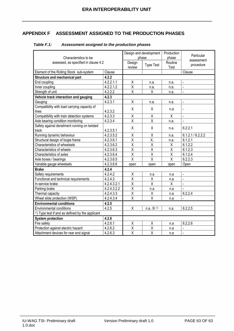
ERA INTEROPERABILITY UNIT
IU-WAG TSI- Preliminary draft 1.0.doc
Version Preliminary draft 1.0 PAGE 63 OF 63
APPENDIX F ASSESSMENT ASSIGNED TO THE PRODUCTION PHASES
Table F.1: Assessment assigned to the production phases
Characteristics to be
assessed, as specified in clause 4.2
Design and development
phase
Production
phase Particular
assessment
procedure Design
review Type Test
Routine
Test
Element of the Rolling Stock sub-system Clause Clause
Structure and mechanical part 4.2.2
End coupling 4.2.2.1.1 X n.a. n.a. -
Inner coupling 4.2.2.1.2 X n.a. n.a. -
Strength of unit 4.2.2.2 X X n.a. -
Vehicle track interaction and gauging 4.2.3
Gauging 4.2.3.1 X n.a. n.a. -
Compatibility with load carrying capacity of
lines 4.2.3.2 X X n.a -
Compatibility with train detection systems 4.2.3.3 X X X -
Axle bearing condition monitoring 4.2.3.4 X X n.a. -
Safety against derailment running on twisted
track 4.2.3.5.1 X X n.a. 6.2.2.1
Running dynamic behaviour 4.2.3.5.2 X X n.a. 6.1.2.1 / 6.2.2.2
Structural design of bogie frame 4.2.3.6.1 X X. n.a. 6.1.2.1
Characteristics of wheelsets 4.2.3.6.2 X X X 6.1.2.2
Characteristics of wheels 4.2.3.6.3 X X X 6.1.2.3
Characteristics of axles 4.2.3.6.4 X X X 6.1.2.4
Axle boxes / bearings 4.2.3.6.5 X X X 6.2.2.3
Variable gauge wheelsets 4.2.3.6.6 open open open Open
Brake 4.2.4
Safety requirements 4.2.4.2 X n.a n.a -
Functional and technical requirements 4.2.4.3 X X n.a -
In-service brake 4.2.4.3.2.1 X X X -
Parking brake 4.2.4.3.2.2 X n.a n.a -
Thermal capacity 4.2.4.3.3 X X n.a 6.2.2.4
Wheel slide protection (WSP) 4.2.4.3.4 X X n.a -
Environmental conditions 4.2.5
Environmental conditions 4.2.5 X n.a. /X (1) n.a. 6.2.2.5 (1) Type test if and as defined by the applicant
System protection 4.2.6
Fire safety 4.2.6.1 X X n.a 6.2.2.6
Protection against electric hazard 4.2.6.2 X X n.a -
Attachment devices for rear end signal 4.2.6.3 X X n.a -