european ets 300 192 telecommunication standard€¦ · 8.6 suspend and resume procedures 19 8.7 te...
TRANSCRIPT

New
pre
sent
atio
n -
see
His
tory
box
EUROPEAN ETS 300 192
TELECOMMUNICATION December 1992
STANDARD
Source: ETSI TC-ECMA Reference: DE/ECMA-106
ICS: 33.080
Key words: PTN, SSIG-BC
Private Telecommunications Network (PTN)Signalling protocol at the S-reference point
Circuit mode basic services
ETSIEuropean Telecommunications Standards Institute
ETSI Secretariat
Postal address: F-06921 Sophia Antipolis CEDEX - FRANCEOffice address: 650 Route des Lucioles - Sophia Antipolis - Valbonne - FRANCEX.400: c=fr, a=atlas, p=etsi, s=secretariat - Internet: [email protected]
Tel.: +33 92 94 42 00 - Fax: +33 93 65 47 16
Copyright Notification: No part may be reproduced except as authorized by written permission. The copyright and theforegoing restriction extend to reproduction in all media.
© European Telecommunications Standards Institute 1992. All rights reserved.

Page 2ETS 300 192: 1992
Whilst every care has been taken in the preparation and publication of this document, errors in content,typographical or otherwise, may occur. If you have comments concerning its accuracy, please write to "ETSIEditing and Committee Support Dept." at the address shown on the title page.

Page 3ETS 300 192: 1992
Table of Contents
Foreword 7
1 Scope 9
2 Conformance 9
3 References 9
4 Definitions 94.1 Basic Call 94.2 Incoming Call 94.3 Outgoing Call 104.4 User and Network 10
5 Acronyms 10
6 General principles 106.1 Protocol model 106.2 Services provided to Call Control 116.3 Services required of the Data Link Layer 11
6.3.1 Acknowledged information transfer services 116.3.2 Unacknowledged information transfer services 12
6.4 Protocol Control states 126.4.1 States for circuit mode Call Control 126.4.2 States for Layer management 12
6.5 Message segmentation and reassembly functions 126.5.1 Null (0) 136.5.2 Receiving segmented message (1) 13
7 General procedures 137.1 Use of the services of Layer 2 13
7.1.1 Establishment of a Data Link connection 137.1.2 Transfer of data 14
7.2 Message segmentation procedures 147.3 Handling of protocol error conditions 14
7.3.1 Addition to requirements of subclause 5.8.6.1 of ETS 300 102-1 147.3.2 Addition to requirements of subclause 5.8.6.2 of ETS 300 102-1 157.3.3 Modification to subclause 5.8.7.1, second paragraph, of ETS 300 102-1 157.3.4 Replacement for items a, b and c of subclause 5.8.7.1 of ETS 300 102-1 157.3.5 Addition to requirements of subclause 5.8.7.2 of ETS 300 102-1 157.3.6 Modification to subclause 5.8.7.2, first paragraph, of ETS 300 102-1 157.3.7 Modification to subclause 5.8.7.2, second paragraph, of ETS 300 102-1 15
7.4 Handling of configuration errors 157.5 Status and status enquiry procedures 16
7.5.1 Modifications to subclause 5.8.10 of ETS 300 102-1 167.5.2 Modifications to subclause 5.8.11 of ETS 300 102-1 16
8 Procedures for circuit mode call control 168.1 Call establishment at the originating interface 16
8.1.1 Addition to subclause 5.1.1 of ETS 300 102-1 16

Page 4ETS 300 192: 1992
8.1.2 Modification to the "ETSI Requirement" concerning en-bloc sending in subclause5.1.1 of ETS 300 102-1 16
8.1.3 Modification to the "ETSI Requirement" concerning the tone option in subclause5.1.3 of ETS 300 102-1 17
8.1.4 Clarification of subclause 5.1.5 of ETS 300 102-1 178.1.5 Modification to subclause 5.1.6 of ETS 300 102-1 178.1.6 Modification to the "ETSI Requirement" concerning the sending of the alerting
message in subclause 5.1.7 of ETS 300 102-1 178.1.7 Modification to the "ETSI Requirement" concerning the receipt of the alerting
message in subclause 5.1.7 of ETS 300 102-1 178.1.8 Addition to subclause 5.1.8 of ETS 300 102-1 178.1.9 Non-applicability of transit network selection 17
8.2 Call Establishment at the destination interface 188.2.1 Addition to subclause 5.2.1 of ETS 300 102-1 188.2.2 Change to case 4 of subclause 5.2.3.1 of ETS 300 102-1 188.2.3 Change to case b of subclause 5.2.3.2 of ETS 300 102-1 188.2.4 Non-applicability of overlap receiving procedure 188.2.5 Replacement of the first paragraph of 5.2.5.2 of ETS 300 102-1 188.2.6 Modification to the "ETSI Requirement" concerning progress description value No.
1 188.2.7 Addition to subclause 5.2.8 of ETS 300 102-1 18
8.3 Call clearing 188.3.1 Replacement of item b of subclause 5.3.2 of ETS 300 102-1 188.3.2 Non applicability of item c of subclause 5.3.2 of ETS 300 102-1 198.3.3 Modification to subclause 5.3.3 of ETS 300 102-1 198.3.4 Modification to subclause 5.3.4.1 of ETS 300 102-1 198.3.5 Modification to subclause 5.3.4.2 of ETS 300 102-1 19
8.4 In-band tones and announcements 198.5 Call collisions 198.6 Suspend and Resume procedures 198.7 TE side and PTN side SDL diagrams (informative) 19
9 Procedures for layer management 199.1 Restart procedures 19
10 List of system parameters 19
11 Functional definition and content of messages 2011.1 Messages for general procedures 21
11.1.1 STATUS 2111.1.2 STATUS EQUIRY 21
11.2 Messages for circuit mode Call Control 2111.2.1 ALERTING 2111.2.2 CALL PROCEEDING 2111.2.3 CONNECT 2111.2.4 CONNECT ACKNOWLEDGE 2211.2.5 DISCONNECT 2211.2.6 INFORMATION 2211.2.7 PROGRESS 2211.2.8 RELEASE 2211.2.9 RELEASE COMPLETE 2211.2.10 RESUME 22

Page 5ETS 300 192: 1992
11.2.11 RESUME ACKNOWLEDGE 2211.2.12 RESUME REJECT 2211.2.13 SETUP 2311.2.14 SETUP ACKNOWLEDGE 2311.2.15 SUSPEND 2311.2.16 SUSPEND ACKNOWLEDGE 2311.2.17 SUSPEND REJECT 23
11.3 Messages for Layer Management 2311.3.1 RESTART 2311.3.2 RESTART ACKNOWLEDGE 23
12 General message format and coding of information elements 2312.1 Overview 2412.2 Protocol discriminator 2412.3 Call reference 2412.4 Message type 2412.5 Other information elements (Codeset 0) 24
12.5.1 Coding rules 2412.5.2 Extensions of codesets 2512.5.3 Locking shift procedure 2512.5.4 Non-locking shift procedure 2612.5.5 Bearer capability 2612.5.6 Call identity 2612.5.7 Call state 2612.5.8 Called party number 2612.5.9 Called party subaddress 2612.5.10 Calling party number 2612.5.11 Calling party subaddress 2712.5.12 Cause 2712.5.13 Channel identification 2712.5.14 Connected number 2712.5.15 Connected subaddress 2712.5.16 Date / time 2812.5.17 Display 2812.5.18 High layer compatibility (Layers 4 - 7) 2812.5.19 Low layer compatibility (Layers 1 - 3) 2812.5.20 Progress indicator 2812.5.21 Restart indicator 2812.5.22 Segmented message 2812.5.23 Sending complete 29
12.6 Information elements of codeset 5 2912.6.1 Party category 29
Annex A (informative): Use of progress indicators 30
Annex B (informative): Use of cause values 31
B.1 Definition of cause values 31
B.2 Use of causes for busy conditions 31
Annex C (informative): Examples of message sequences 32
Page 6ETS 300 192: 1992
C.1 En-bloc sending 32C.1.1 Successful call setup 32C.1.2 Unsuccessful call setup 32
C.2 Overlap sending 33C.2.1 Successful call setup 33C.2.2 Unsuccessful call setup 33
C.3 Call clearing 34
Annex D (informative): Manufacturer specific information 35
Annex E (informative): Bibliography 36
Annex F (informative): Terminal interchangeability 37
History 38

Page 7ETS 300 192: 1992
Foreword
This European Telecommunication Standard (ETS) has been produced by the European Computer ManufacturersAssociation (ECMA) on behalf of its members and those of the European Telecommunications Standards Institute(ETSI).
This ETS defines the signalling protocol for use at the S-reference point in support of basic circuit mode services. It isintended to be supported by a suitable layer 2 protocol, e.g. ETS 300 169, in the D-channel of a basic access interfaceor a primary rate access interface.
The protocol defined in this ETS is based upon that specified in ETS 300 102-1. ETS 300 102-1 is applicable tointerfaces to public ISDNs at the T reference point, or at coincident S and T reference points if there is no NT2function. This ETS references many of the Clauses of ETS 300 102-1 to avoid reproducing large quantities of text.Some of the options in ETS 300 102-1 are not applicable to interfaces at the S reference point, and therefore areexcluded by this standard. On the other hand, certain additions have been identified as being required at the Sreference point. However, the major part of the protocol is identical with that specified in ETS 300 102-1, enablingTEs to be designed which are compatible with both PTNs and public ISDNs and can therefore be connected to either.
This ETS refers to ETS 300 102-2 for the description of the protocol in SDL form.
This ETS was produced by ECMA using the ECMA guidelines for the production of standards and using the ECMAstylesheet. In order to avoid undue delays in the publication of this ETS it has been agreed that this ETS will not beconverted to the ETSI stylesheet.

Page 8ETS 300 192: 1992
Blank page

Page 9ETS 300 192: 1992
1 Scope
This standard defines the Layer 3 protocol for signalling for the support of circuit-mode bearer services (usedeither on their own or in support of teleservices) at an interface at the S reference point between a TerminalEquipment (TE) and a Private Telecommunication Network (PTN). The S reference point is defined in ENV41004.
This standard is based upon ETS 300 102-1, which defines the equivalent protocol for the T and coincident Tand S reference points between a user and a public ISDN. Many of the Clauses of ETS 300 102-1 areincorporated by reference. Any reference in the text of ETS 300 102-1 to Annex D of that document are notapplicable to this standard. Annex F contains information on terminal interchangeability between PTNs andpublic ISDNs.
This standard is applicable to basic and primary rate accesses of PTNXs and to TEs that are intended forconnection to such accesses.
The conveyance of non-standardized (e.g. manufacturer-specific) information in messages is outside the scopeof this standard. Annex D discusses ways in which this can be achieved.
2 Conformance
In order to conform to this standard, a PTNX shall satisfy the PTN requirements and a TE shall satisfy the TErequirements contained in Clauses 7, 8, 9, 10, 11 and 12 of this standard.
3 References
ETS-300 102-1 Integrated Services Digital Network (ISDN); User-network interface layer 3,Specifications for basic call control (1990).
I-ETS 300 169 Private Telecommunication Network (PTN); Signalling at the S-referencepoint, Data link layer protocol (1992).
ETS 300 171 Private Telecommunication Network (PTN); Specification, functionalmodels and information flows, Control aspects of circuit mode basic services(1992).
ETS 300 189 Private Telecommunication Network (PTN); Addressing (1992).
CCITT Recommendation I.112 "Blue Book", 1988 - Vocabulary of Terms for ISDNs.
ENV 41004 Reference Configurations for Calls through Exchanges of PrivateTelecommunication Networks.
ENV 41005 Method for the Specification of Basic and Supplementary Services of PrivateTelecommunication Networks.
ENV 41007 Definition of Terms in Private Telecommunication Networks.
4 Definitions
For the purpose of this standard the terminology defined in ENV 41007 and CCITT Recommendation I.112applies. If there is conflict, the definitions in ENV 41007 shall take precedence. In addition the followingdefinitions apply.
4.1 Basic Call
A single invocation of a basic service according to ETS 300 171.
4.2 Incoming Call
A call presented to the TE by the PTN.

Page 10ETS 300 192: 1992
4.3 Outgoing Call
A call presented to the PTN by the TE.
4.4 User and Network
Throughout this standard, reference is made to Clauses in ETS 300 102-1. When applying a Clause inETS-300 102-1 to the TE-PTN interface, the term user shall be interpreted as TE, and the term networkshall be interpreted as PTN.
5 Acronyms
CLIP Calling Line Identification Presentation
COLP Connected Line Identification Presentation
ISDN Integrated Services Digital Network
MSI Manufacturer Specific Information
PTN Private Telecommunication Network
PTNX Private Telecommunication Network eXchange
SAP Service Access Point
TE Terminal Equipment
6 General principles
This standard specifies the signalling procedures for establishing, maintaining and clearing a basic circuit-switched call at a PTN user access. These signalling procedures are defined in terms of messages exchangedover a data link connection on the D-channel of a basic or primary rate interface structure. The result ofsuccessful basic call establishment is a connection for the purpose of user information transfer. Thisconnection uses a B-channel of a basic or primary rate interface structure.
Throughout this standard, the term B-channel is used to indicate any channel other than the D-channel.
The basic call signalling procedures specified in this standard apply to circuit mode bearer services, usedeither on their own or in support of teleservices.
In addition, this standard includes signalling procedures for layer management, including restart.
6.1 Protocol model
Figure 1 shows the relationship, within the Control Plane, between the layer 3 protocol at the S referencepoint, the protocol entities in the TE and PTN, and the adjacent layers.

Page 11ETS 300 192: 1992
CALLCONTROL
CALLCONTROL
PROTOCOL CONTROL
PROTOCOL CONTROL
LAYER 2
LAYER 1
LAYER 2
LAYER 1
TE-PTNINTERFACE
LAYER 3
PROTOCOL
TE PTN
LAYER 2 SERVICEACCESS POINT
Figure 1 - Protocol model
The Protocol Control entity provides services to Call Control. Call Control corresponds to the functionalentities identified for the basic call at Stage 2 (see ETS 300 171), i.e., the Call Control functional entitywithin the PTN (PTNX) and the Call Control Agent functional entity within the TE. Primitives exchangedacross the boundary between Call Control and Protocol Control correspond to the information flowsexchanged between the Call Control and Call Control Agent functional entities, as identified at Stage 2.Protocol Control provides the mapping between these primitives and the messages transferred across theTE-PTN interface.
In order to transfer messages, Protocol Control uses the services of the Data Link Layer, as available at theData Link Layer Service Access Point (SAP). The Data Link Layer in turn uses the services of the PhysicalLayer.
6.2 Services provided to Call Control
Protocol Control provides services to Call Control whereby Call Control can send information flows to andreceive information flows from the peer Call Control. A primitive from Call Control to Protocol Control oftype "request" or "response" normally results in the associated information flow being presented to the peerCall Control as a primitive of type "indication" or "confirmation" respectively.
PTN side primitives are as listed in subclause 5.3 of ETS 300 102-2. TE side primitives are as listed insubclause 6.3 of ETS 300 102-2.
Note 1:These primitive names differ from the information flow names specified at Stage 2 in ETS 300 171.
6.3 Services required of the Data Link Layer
Services provided by the Data Link Layer and the associated primitives are defined in I-ETS 300 169.Protocol Control uses the following services:
6.3.1 Acknowledged information transfer services
- Data Transfer, using the DL-DATA-REQUEST/INDICATION primitives;
- Establishment of Multiple Frame Operation, using the DL-ESTABLISH-REQUEST/INDICATION/-CONFIRM primitives;

Page 12ETS 300 192: 1992
- Termination of Multiple Frame Operation, using the DL-RELEASE-REQUEST/INDICATION/-CONFIRM primitives.
6.3.2 Unacknowledged information transfer services
- Data Transfer, using the DL-UNIT-DATA-REQUEST/INDICATION primitives.
6.4 Protocol Control states
Protocol Control procedures for calls and layer management are specified in terms of:
- messages which are transferred across the TE-PTN interface;
- the primitives to and from Call Control at the TE side and the PTN side of the TE-PTN interface;
- the information processing and actions that take place within Protocol Control at the TE side and thePTN side of the TE-PTN interface; and
- the states that can exist within Protocol Control at the TE side and the PTN side of the TE-PTNinterface.
State machines are deemed to exist for each circuit mode call. A further state machine is deemed to existfor layer management, covering restart procedures.
6.4.1 States for circuit mode Call Control
The call states defined in subclause 2.1.1 of ETS 300 102-1 for the user side of the user-networkinterface apply also to the TE side of the TE-PTN interface.
Note 2:If the TE does not support the optional suspend and resume procedures of subclause 8.6, states U15 andU17 will never be entered.
The call states defined in subclause 2.1.2 of ETS 300 102-1 for the network side of the user-networkinterface apply also to the PTN side of the TE-PTN interface.
Note 3:If the PTN does not support the optional suspend and resume procedures of subclause 8.6, states N15and N17 will never be entered.
6.4.2 States for Layer management
The states defined in subclause 2.4.1 of ETS 300 102-1 for use in association with the global callreference at the user side of the user-network interface apply also to the TE side of the TE-PTNinterface.
The states defined in subclause 2.4.2 of ETS 300 102-1 for use in association with the global callreference at the network side of the user-network interface apply also to the PTN side of the TE-PTNinterface.
6.5 Message segmentation and reassembly functions
Message segmentation and reassembly functions are employed where the size of a message exceeds themaximum size of the Data Link Layer information field size. The architectural relationship ofsegmentation and reassembly functions to other Protocol Control functions is shown in figure 2.

Page 13ETS 300 192: 1992
OTHER FUNCTIONS
SEGMENTATIONAND REASSEMBLY FUNCTIONS
PROTOCOLDISCRIMINATOR FILTER
CALL CONTROL
PROTOCOLCONTROL
DATA LINK LAYER
Figure 2 - Logical architecture of Protocol Control showing segmentation and reassembly functions
Segmentation and reassembly, where provided, effectively constitutes a lower sub-layer of ProtocolControl. The only function of Protocol Control which lies below the segmentation and reassembly functionsis the filtering out of messages containing a protocol discriminator which is not in accordance with thatspecified.
The primitives across the boundary between segmentation and reassembly functions and other functions arethe same as those between the Data Link Layer and Protocol Control. The segmentation functions act uponDL-DATA-REQUEST primitives by converting, where necessary, a single primitive into two or moreprimitives before passing to the Data Link Layer. The reassembly functions act upon DL-DATA-INDICATION primitives from the Data Link Layer by converting, where necessary, two or moreprimitives into a single primitive for passing up to the other functions of Protocol Control. Other primitivesto and from the Data Link Layer are not affected by the segmentation and reassembly functions.
Message segmentation and reassembly procedures are each specified in terms of a state machine. Messagesegmentation uses a single state, Null (0). Message reassembly uses two states, as listed below.
6.5.1 Null (0)
No message is being reassembled.
6.5.2 Receiving segmented message (1)
One or more segments of a segmented message have been received and one or more further segments areawaited.
7 General procedures
7.1 Use of the services of Layer 2
7.1.1 Establishment of a Data Link connection
Before the procedures for call control, layer management or any of the general procedures in subclauses7.2 to 7.4 can be performed, a Data Link connection must be established between the PTN and the TE.

Page 14ETS 300 192: 1992
The exception is the sending of a SETUP message by the PTN using the unacknowledged informationtransfer service of the Data Link Layer.
If a Data Link connection has not already been established, Protocol Control can request establishmentby sending a DL-ESTABLISH-REQUEST primitive to the Data Link Layer. Receipt of a DL-ESTABLISH-CONFIRMATION primitive or a DL-ESTABLISH-INDICATION primitive from the DataLink Layer indicates that a Data Link connection has been established.
7.1.2 Transfer of data
If a multi-point configuration exists at an interface, or if the PTN does not know whether theconfiguration is multi-point or point-to-point, a SETUP message sent by the PTN shall use theunacknowledged data transfer service (broadcast Data Link) of the Data Link Layer. A message (ormessage segment) shall be transmitted by including it within a DL-UNIT-DATA-REQUEST primitive tothe Data Link Layer. A received message (or message segment) will appear included with a DL-UNIT-DATA-INDICATION primitive from the Data Link Layer.
All other messages shall use the acknowledged data transfer service of the Data Link Layer (point-to-point Data Link). A message (or message segment) shall be transmitted by including it with a DL-DATA-REQUEST primitive to the Data Link Layer. A received message (or message segment) willappear included within a DL-DATA-INDICATION primitive from the Data Link Layer.
Note 4:Before a TE can respond to a SETUP message delivered using the unacknowledged data transfer service,it must establish a Data Link connection according to the procedures of subclause 7.1.1, unless a DataLink connection already exists between the PTN and that TE.
7.2 Message segmentation procedures
This subclause specifies message segmentation and reassembly procedures for messages whose lengthexceeds the maximum size of the Data Link Layer information field. The maximum Data Link Layerinformation field size is defined in ETS 300 169 (parameter N201).
A PTN or a TE shall conform to the message segmentation procedures if it is capable of transmitting amessage which exceeds the maximum size of the Data Link Layer information field. Segmentationprocedures shall not be applied to messages which do not exceed the maximum size of the Data Link Layerinformation field.
A PTN or a TE which claims conformance to this standard shall declare the maximum size of messagewhich it is able to receive. The declared maximum size shall not be less than 260 octets. If the maximumsize of the Data Link Layer information field is less than the declared maximum size of message which canbe received, the PTN or TE shall conform to the message reassembly procedures.
The message segmentation and reassembly procedures of Annex K of ETS 300 102-1 shall apply except therequirement in Clause K.1.
If a segmented message is received by a PTN or TE which does not support reassembly procedures, theprocedures specified in subclause 5.8.4 of ETS 300 102-1 for message type errors shall apply to eachreceived segment.
7.3 Handling of protocol error conditions
The requirements of subclauses 5.8.1 to 5.8.9 of ETS 300 102-1 shall apply with the followingclarifications and additions.
7.3.1 Addition to requirements of subclause 5.8.6.1 of ETS 300 102-1
When a RELEASE message which contains no Cause information element is received as a first clearingmessage, the actions to be taken shall be the same as if a RELEASE message with Cause No. 31 "normal,

Page 15ETS 300 192: 1992
unspecified" had been received, except that if a RELEASE COMPLETE message is sent, it shall containCause No. 96 "mandatory information element is missing".
7.3.2 Addition to requirements of subclause 5.8.6.2 of ETS 300 102-1
When a RELEASE message with invalid content of the Cause information element is received as a firstclearing message, the actions to be taken shall be the same as if a RELEASE message with Cause No. 31"normal, unspecified" had been received, except that if a RELEASE COMPLETE message is sent, itshall contain Cause No. 100 "invalid information element contents".
7.3.3 Modification to subclause 5.8.7.1, second paragraph, of ETS 300 102-1
When the unrecognised information element occurs in a message other than DISCONNECT, RELEASE,or RELEASE COMPLETE the STATUS message, if sent, shall indicate the call state that the receivingentity enters after processing the message in which the unrecognised information element was received.
7.3.4 Replacement for items a, b and c of subclause 5.8.7.1 of ETS 300 102-1
a) When a DISCONNECT message is received which has one or more unrecognized informationelements, the actions taken shall be the same as if a DISCONNECT message had beenreceived without these unrecognized information elements with the exception that theRELEASE message returned shall contain Cause No. 99 "information element non-existent".It is recommended to provide Cause No. 99 with diagnostics, although the inclusion ofdiagnostics is optional.
b) When a RELEASE message is received which has one or more unrecognized informationelements, the actions taken shall be the same as if a RELEASE message had been receivedwithout these unrecognized information elements with the exception that the RELEASECOMPLETE message returned shall contain Cause No. 99 "information element non-existent". It is recommended to provide Cause No. 99 with diagnostics, although the inclusionof diagnostics is optional.
c) When a RELEASE COMPLETE message is received which has one or more unrecognizedinformation elements, the actions taken shall be the same as if a RELEASE COMPLETEmessage without these unrecognized information elements had been received.
7.3.5 Addition to requirements of subclause 5.8.7.2 of ETS 300 102-1
If a DISCONNECT, RELEASE or RELEASE COMPLETE message is received which has one or morenon-mandatory information elements with invalid contents, normal call clearing shall apply. TheRELEASE and RELEASE COMPLETE messages returned shall contain Cause No. 100 "invalidinformation element contents". It is recommended to provide Cause No. 100 with diagnostics, althoughthe inclusion of diagnostics is optional.
7.3.6 Modification to subclause 5.8.7.2, first paragraph, of ETS 300 102-1
When the information element with content error occurs in a message other than DISCONNECT,RELEASE, or RELEASE COMPLETE the STATUS message, if sent, shall indicate the call state that thereceiving entity enters after processing the message in which the information element with content errorwas received.
7.3.7 Modification to subclause 5.8.7.2, second paragraph, of ETS 300 102-1
Access information elements with a length exceeding the maximum length shall be treated as havingcontent error, i.e. they shall not be truncated and processed.
7.4 Handling of configuration errors
In point-to-multipoint configurations at the TE-PTN interface, the PTN capability may be limited bymanufacturer declaration. This means that the PTN may accept only a limited number of positive responses
Page 16ETS 300 192: 1992
to a SETUP message which was delivered using the broadcast data link. If the number of positivelyresponding TEs, as defined by the data link on which an initial responding message (i.e., CALLPROCEEDING, ALERTING or CONNECT) is received, reaches the limit, any additional positive responseshall be rejected. Depending on implementation, the PTN shall either send a RELEASE COMPLETEmessage containing Cause No. 47 "Resource unavailable, unspecified" or initiate normal call clearing usingthe same Cause number.
Note 5:It is the user's responsibility to configure a basic access in accordance with the particular PTN's limitation.
7.5 Status and status enquiry procedures
The requirements of subclauses 5.8.10 to 5.8.11 of ETS 300 102-1 shall apply with the followingamendments.
7.5.1 Modifications to subclause 5.8.10 of ETS 300 102-1
The requirements of the paragraph beginning with "The sending or receipt of the STATUS ENQUIRYmessage..." shall be modified as follows.
A STATUS message containing Cause No. 97 shall not be treated as a response to the STATUSENQUIRY message.
7.5.2 Modifications to subclause 5.8.11 of ETS 300 102-1
The requirements of the paragraph beginning with "A STATUS message may be received..." and theparagraph beginning with "In this case the actions..." shall be replaced by the following.
On receipt of a STATUS message indicating a compatible protocol control state but containing one ofthe Causes No. 96, No. 97, No. 99, or No. 100, the receiving entity should attempt to analyse the contentsof the received STATUS message considering the current stage of the call in order to determine whetheror not the call can continue. The actions to be taken are an implementation option.
8 Procedures for circuit mode call control
The call states referred to in this section cover the states perceived by the PTN, states perceived by the TE andstates which are common to both TE and PTN. Unless specifically qualified, all states described in thefollowing text shall be understood as common.
As a general principle, any message sent by the PTN to the TE may contain a Display information elementwhose contents may be displayed by the TE.
In addition to the messages exchanged as described in the following subclauses, INFORMATION messagesfor call control may be sent by the TE or by the PTN only after the first response to a SETUP message hasbeen sent or received, and before clearing of the call reference is initiated. An INFORMATION messagereceived in the Release Request state may be ignored.
8.1 Call establishment at the originating interface
The requirements of subclause 5.1 of ETS 300 102-1 shall apply with the following additions andmodifications.
8.1.1 Addition to subclause 5.1.1 of ETS 300 102-1
Address information elements shall be handled as specified in ETS 300 189.
8.1.2 Modification to the "ETSI Requirement" concerning en-bloc sending in subclause 5.1.1 ofETS 300 102-1
The #-character shall not be used as sending complete indication.
Page 17ETS 300 192: 1992
8.1.3 Modification to the "ETSI Requirement" concerning the tone option in subclause 5.1.3 ofETS 300 102-1
If the PTN provides dial tone to the TE, the progress description value No. 8 shall be included in theSETUP ACKNOWLEDGE message. The "tone option" should be interpreted as the need to return dialtone in the case where the Bearer capability information element indicates an appropriate Bearercapability, e.g. "3,1 kHz audio" or "speech". The TE may attach to the B-channel on receipt of theSETUP ACKNOWLEDGE message with the Progress description value No. 8.
Note 6:The attachment to the B-channel by the TE at this point is recommended, when the network providedtones or announcements are of use.
8.1.4 Clarification of subclause 5.1.5 of ETS 300 102-1
The indicated Causes in subclause 5.1.5 of ETS 300 102-1 for rejecting a call because the requestedservice is not authorized or is not available, are only examples. Other Causes are possible in this case.
8.1.5 Modification to subclause 5.1.6 of ETS 300 102-1
The requirements in subclause 5.1.6 of ETS 300 102-1 for receipt of a Progress indicator informationelement shall be replaced by the following requirement.
If the Progress indication information element is included in a call control message, the proceduresspecified in the rest of subclause 5.1 shall apply. If the Progress indicator information element isincluded in the PROGRESS message, no state change shall occur but supervisory timer T310 shall bestopped if progress description value No. 1, 2 or 8 is included in the PROGRESS message. In both casesthe user shall connect to the B-channel (if not already connected) if progress description value No. 1 or 8is included.
8.1.6 Modification to the "ETSI Requirement" concerning the sending of the alerting message insubclause 5.1.7 of ETS 300 102-1
The first "ETSI Requirement" in subclause 5.1.7 of ETS 300 102-1 concerning the sending of theALERTING message shall be replaced by the following requirement.
For services which require an in-band tone or announcement to be supplied to the calling TE during theperiod of alerting, the PTN shall connect the appropriate tone or announcement to the B-channel.
8.1.7 Modification to the "ETSI Requirement" concerning the receipt of the alerting message insubclause 5.1.7 of ETS 300 102-1
The second "ETSI Requirement" in subclause 5.1.7 of ETS 300 102-1 concerning the receipt of theALERTING message shall be replaced by the following requirement.
When the TE receives the ALERTING message with Progress description value No. 1 or No. 8 of theProgress indicator information element included in the message, the TE may attach to the B-channel (ifnot attached already). The TE shall attach to the B-channel on receipt of the CONNECT message if notalready attached.
8.1.8 Addition to subclause 5.1.8 of ETS 300 102-1
The PTN shall support the transfer of the Low layer compatibility information element transparently inboth directions in the SETUP and the CONNECT message if it is provided by the calling TE (using theSETUP message) or by the called TE (using the CONNECT message). The requirements of Annex M andof Annex L, Clauses L.1 and L.2, of ETS 300 102-1 shall apply.
8.1.9 Non-applicability of transit network selection
The transit network selection, described in subclause 5.1.10 of ETS 300 102-1, is outside the scope ofthis standard.

Page 18ETS 300 192: 1992
8.2 Call Establishment at the destination interface
The requirements of subclause 5.2 of ETS 300 102-1 shall apply with the following modifications.
8.2.1 Addition to subclause 5.2.1 of ETS 300 102-1
Address information elements shall be handled as specified in ETS 300 189.
8.2.2 Change to case 4 of subclause 5.2.3.1 of ETS 300 102-1
In case 4 "no B-channel available" of the channel selection procedure the TE shall be allowed to rejectthe call by sending a RELEASE COMPLETE message with the Cause No. 34 (free TE) or No. 17 (busyTE). Alternative actions whereby the user employs supplementary services in order to proceed with thecall are outside the scope of this standard.
8.2.3 Change to case b of subclause 5.2.3.2 of ETS 300 102-1
In case b "no B-channel available" of the channel selection procedure the TE shall be allowed to rejectthe call by sending a RELEASE COMPLETE message with the Cause No. 34 (free TE) or No. 17 (busyTE). Alternative actions whereby the user employs supplementary services in order to proceed with thecall are outside the scope of this standard.
8.2.4 Non-applicability of overlap receiving procedure
The overlap receiving procedure described in subclauses 5.2.1 and 5.2.4 of ETS 300 102-1 shall not beused, but only the en-bloc receiving procedure. Complete called party number information shall alwaysbe sent in the SETUP message.
8.2.5 Replacement of the first paragraph of 5.2.5.2 of ETS 300 102-1
When the SETUP message is delivered on a broadcast data link, the PTN shall maintain a state machinethat tracks the overall progression of the incoming call. The PTN shall also maintain an associated callstate, up to an implementation dependent number, for each responding TE as determined by the data linkon which a message is received.
8.2.6 Modification to the "ETSI Requirement" concerning progress description value No. 1
On receipt of a PROGRESS message with the Progress description value No. 1, the PTN shall stop onlysupervisory timer T310.
8.2.7 Addition to subclause 5.2.8 of ETS 300 102-1
The PTN shall support the transfer of the Low layer compatibility information element transparently inboth directions in the SETUP and the CONNECT message if it is provided by the calling TE (using theSETUP message) or by the called TE (using the CONNECT message). The requirements of Annex M andof Annex L, Clauses L.1 and L.2, of ETS 300 102-1 shall apply.
The PTN shall connect the B-channel in both directions on receipt of the CONNECT message from thecalled TE. Optionally, and if the SETUP message was delivered on a point-to-point Data Link, throughconnection may occur in one or both directions at an earlier stage, but not before completion of channelnegotiation at the destination interface.
8.3 Call clearing
The requirements of subclause 5.3 of ETS 300 102-1 shall apply with the following amendments.
8.3.1 Replacement of item b of subclause 5.3.2 of ETS 300 102-1
If a SETUP message has been delivered on the broadcast data link, the PTN shall initiate the clearing ofa responding TE which is not awarded the call by sending a RELEASE message or, if the PTN is unableto establish a state machine for the TE, by sending a RELEASE COMPLETE message. The RELEASE orRELEASE COMPLETE message shall contain cause No. 26 "non-selected user clearing".

Page 19ETS 300 192: 1992
8.3.2 Non applicability of item c of subclause 5.3.2 of ETS 300 102-1
Subclause 5.3.2 of ETS 300 102-1 item c) shall not apply.
8.3.3 Modification to subclause 5.3.3 of ETS 300 102-1
A second Cause information element shall not be used in a clearing message.
8.3.4 Modification to subclause 5.3.4.1 of ETS 300 102-1
A second Cause information element shall not be used in a clearing message.
8.3.5 Modification to subclause 5.3.4.2 of ETS 300 102-1
A second Cause information element shall not be used in a clearing message.
8.4 In-band tones and announcements
The requirements of subclause 5.4 of ETS 300 102-1 shall apply with the exception of Note 3.
8.5 Call collisions
The requirements of subclause 5.7 of ETS 300 102-1 shall apply.
8.6 Suspend and Resume procedures
These procedures are optional for TEs and for PTNs.
The requirements of subclause 5.6 of ETS 300 102-1 shall apply with the following exceptions.
1) The "ETSI Requirement" permitting some networks only to support a maximum length of theCall identity value of two octets shall not apply.
2) Subclause 5.6.7 shall not apply.
3) The sending of the NOTIFY message is outside the scope of this standard.
Note 7:The use of these procedures in support of the Terminal Portability supplementary service is outside thescope of this standard.
8.7 TE side and PTN side SDL diagrams (informative)
The user side and network side Specification and Description Language (SDL) diagrams contained inETS 300 102-2 may also be used to provide additional clarification of the procedures described in thisstandard, except for those aspects which conflict with differences between this standard andETS 300 102-1. The differences specified in subclauses 7.4, 7.5, 8.1.5, 8.2.2, 8.2.3, 8.2.4 and 8.3.2 of thisstandard are not reflected in the SDL diagrams of ETS 300 102-2.
9 Procedures for layer management
9.1 Restart procedures
The requirements of subclause 5.5 of ETS 300 102-1 shall apply.
ETS 300 102-2 contains (informative) SDL diagrams of the Restart procedures, which may be used toprovide additional clarification of these procedures.
10 List of system parameters
The requirements of Clause 9 of ETS 300 102-1 shall apply with the following amendments.
1) All TE side timer values shall have a tolerance of 5%; all PTN side timer values shall have atolerance of 10%.
2) TE side timer T310 shall have a value in the range 30 s to 120 s.

Page 20ETS 300 192: 1992
Note 8:It is recommended that, if TE side timer T310 is implemented, a value near to the upper end of therange be chosen to avoid problems when routeing is delayed, e.g. while waiting for resources.
3) Timer T320 and timer T321 are not used.
11 Functional definition and content of messages
The procedures of this standard make use of the following messages listed in table 1.
Table 1 - Messages
ÚÄÄÄÄÄÄÄÄÄÄÄÄÄÄÄÄÄÄÄÄÄÄÄÄÄÄÄÄÄÄÄÄÄÄ¿³ Call establishment messages: ³³ ³³ ALERTING ³³ CALL PROCEEDING ³³ CONNECT ³³ CONNECT ACKNOWLEDGE ³³ PROGRESS ³³ SETUP ³³ SETUP ACKNOWLEDGE ³³ ³³ ³³ Call information phase messages: ³³ ³³ RESUME ³³ RESUME ACKNOWLEDGE ³³ RESUME REJECT ³³ SUSPEND ³³ SUSPEND ACKNOWLEDGE ³³ SUSPEND REJECT ³³ ³³ ³³ Call clearing messages: ³³ ³³ DISCONNECT ³³ RELEASE ³³ RELEASE COMPLETE ³³ ³³ ³³ Layer management messages: ³³ ³³ RESTART ³³ RESTART ACKNOWLEDGE ³³ ³³ ³³ Miscellaneous messages: ³³ ³³ INFORMATION ³³ STATUS ³³ STATUS ENQUIRY ³³ ³ÀÄÄÄÄÄÄÄÄÄÄÄÄÄÄÄÄÄÄÄÄÄÄÄÄÄÄÄÄÄÄÄÄÄÄÙ
This Clause defines each of these messages by means of a reference to the corresponding Clause of ETS300 102-1 which describes the particular message, supplemented by a description of the differences in thosecases where this standard differs from ETS 300 102-1.
Each definition in ETS 300 102-1 includes:
a) A brief description of the direction, significance and use of that message.
Statements in ETS 300 102-1 concerning the significance of a message shall be ignored.
b) A table listing the information elements of codeset 0 in the order of their appearance in the message(same relative order for all message types). For each information element the table indicates:
- the Clause of ETS 300 102-1 describing the information element (Clause 12 below defines allthe information elements used for this standard);
- the direction in which it may be sent ['n u', meaning network to user (PTN to TE), 'u n',meaning user to network (TE to PTN) or both];

Page 21ETS 300 192: 1992
- whether inclusion is mandatory (M) or optional (O), with a reference to notes explaining thecircumstances under which the information element shall be included;
- the length (or length range) of the information element, in octets, where * denotes an undefinedmaximum length which may be network or service dependent.
c) Further explanatory notes, as necessary.
Additional elements in codeset 5 are specified in this standard. Note, however, that the shift from codeset 0 tocodeset 5 is not explicitly shown.
Since this standard only deals with basic call control, all messages and information elements ofETS 300 102-1 that do not pertain to basic services as defined in ETS 300 171 are excluded from its scope.This means that support of these messages and information elements is not required in order to conform tothis standard.
Note 9:Other messages and information elements than those defined here will be required for the support ofsupplementary services and Additional Network Features (ANFs); these will be defined in other standards.
11.1 Messages for general procedures
11.1.1 STATUS
The requirements of subclause 3.1.18 and of subclause 3.4.3 of ETS 300 102-1 shall apply.
11.1.2 STATUS EQUIRY
The requirements of subclause 3.1.19 of ETS 300 102-1 shall apply.
11.2 Messages for circuit mode Call Control
11.2.1 ALERTING
The requirements of subclause 3.1.1 of ETS 300 102-1 shall apply, with the following modifications:
- the information elements 'Facility' and 'User-user' are outside the scope of this standard;
- the last statement of Note 2, explaining the use of 'Progress indicator' in the direction 'user tonetwork', shall not apply since Annex N is not applicable;
- the following codeset 5 information element may also be included:
Table 2 - Information element of codeset 5
ÚÄÄÄÄÄÄÄÄÄÄÄÄÄÄÄÄÄÄÄÄÄÂÄÄÄÄÄÄÄÄÄÄÄÂÄÄÄÄÄÄÄÄÄÄÄÂÄÄÄÄÄÄÂÄÄÄÄÄÄÄÄ¿³ Information Element ³ Reference ³ Direction ³ Type ³ Length ³ÃÄÄÄÄÄÄÄÄÄÄÄÄÄÄÄÄÄÄÄÄÄÅÄÄÄÄÄÄÄÄÄÄÄÅÄÄÄÄÄÄÄÄÄÄÄÅÄÄÄÄÄÄÅÄÄÄÄÄÄÄÄ´³ Party category ³ 12.6 ³ n u ³ 0 ³ 4 ³ÀÄÄÄÄÄÄÄÄÄÄÄÄÄÄÄÄÄÄÄÄÄÁÄÄÄÄÄÄÄÄÄÄÄÁÄÄÄÄÄÄÄÄÄÄÄÁÄÄÄÄÄÄÁÄÄÄÄÄÄÄÄÙ
11.2.2 CALL PROCEEDING
The requirements of subclause 3.1.2 of ETS 300 102-1 shall apply, with the following exception:
- the last statement of Note 3, explaining the use of 'Progress indicator' in the direction 'user tonetwork', shall not apply since Annex N is not applicable.
11.2.3 CONNECT
The requirements of subclause 3.1.4 of ETS 300 102-1 shall apply, with the following modifications:
- the information elements 'Facility' and 'User-user' are outside the scope of this standard;
- the following information elements may also be included:

Page 22ETS 300 192: 1992
Table 3 - Additional information elements
ÚÄÄÄÄÄÄÄÄÄÄÄÄÄÄÄÄÄÄÄÄÄÂÄÄÄÄÄÄÄÄÄÄÄÂÄÄÄÄÄÄÄÄÄÄÄÄÄÄÄÄÄÄÄÄÄÄÄÄÄÂÄÄÄÄÄÄÂÄÄÄÄÄÄÄÄ¿³ Information Element ³ Reference ³ Direction ³ Type ³ Length ³ÃÄÄÄÄÄÄÄÄÄÄÄÄÄÄÄÄÄÄÄÄÄÅÄÄÄÄÄÄÄÄÄÄÄÅÄÄÄÄÄÄÄÄÄÄÄÄÄÄÄÄÄÄÄÄÄÄÄÄÄÅÄÄÄÄÄÄÅÄÄÄÄÄÄÄÄ´³ Connected number ³ 12.5 ³ u n (Notes 10 and 11)³ 0 ³ 4-24 ³ÃÄÄÄÄÄÄÄÄÄÄÄÄÄÄÄÄÄÄÄÄÄÅÄÄÄÄÄÄÄÄÄÄÄÅÄÄÄÄÄÄÄÄÄÄÄÄÄÄÄÄÄÄÄÄÄÄÄÄÄÅÄÄÄÄÄÄÅÄÄÄÄÄÄÄÄ´³ Connected subaddress³ 12.5 ³ u n (Note 10) ³ 0 ³ 4-23 ³ÃÄÄÄÄÄÄÄÄÄÄÄÄÄÄÄÄÄÄÄÄÄÅÄÄÄÄÄÄÄÄÄÄÄÅÄÄÄÄÄÄÄÄÄÄÄÄÄÄÄÄÄÄÄÄÄÄÄÄÄÅÄÄÄÄÄÄÅÄÄÄÄÄÄÄÄ´³ Party category ³ 12.6 ³ n u ³ 0 ³ 4 ³ÀÄÄÄÄÄÄÄÄÄÄÄÄÄÄÄÄÄÄÄÄÄÁÄÄÄÄÄÄÄÄÄÄÄÁÄÄÄÄÄÄÄÄÄÄÄÄÄÄÄÄÄÄÄÄÄÄÄÄÄÁÄÄÄÄÄÄÁÄÄÄÄÄÄÄÄÙ
Note 10:Inclusion in the direction user-to-network shall be in accordance with the provisions of ETS 300 189.Inclusion in the direction network-to-user is part of the supplementary service COLP.
Note 11:Information element Connected number is relevant only in the context of a multiple subscriber numberarrangement at the access.
11.2.4 CONNECT ACKNOWLEDGE
The requirements of subclause 3.1.5 of ETS 300 102-1 shall apply.
11.2.5 DISCONNECT
The requirements of subclause 3.1.6 of ETS 300 102-1 shall apply, with the following exception:
- the information elements 'Facility' and 'User-user' are outside the scope of this standard.
11.2.6 INFORMATION
The requirements of subclause 3.1.8 of ETS 300 102-1 shall apply, with the following exceptions:
- the information element 'Keypad facility' is outside the scope of this standard;
- the network option 'Inclusion of the 'Cause' information element' shall not apply.
11.2.7 PROGRESS
The requirements of subclause 3.1.10 of ETS 300 102-1 shall apply, with the following exception:
- the information element 'User-user' is outside the scope of this standard.
11.2.8 RELEASE
The requirements of subclause 3.1.11 of ETS 300 102-1 shall apply, with the following exception:
- the information elements 'Facility' and 'User-user' are outside the scope of this standard.
11.2.9 RELEASE COMPLETE
The requirements of subclause 3.1.12 of ETS 300 102-1 shall apply, with the following exception:
- the information elements 'Facility' and 'User-user' are outside the scope of this standard.
11.2.10 RESUME
The requirements of subclause 3.1.13 of ETS 300 102-1 shall apply.
11.2.11 RESUME ACKNOWLEDGE
The requirements of subclause 3.1.14 of ETS 300 102-1 shall apply.
11.2.12 RESUME REJECT
The requirements of subclause 3.1.15 of ETS 300 102-1 shall apply.

Page 23ETS 300 192: 1992
11.2.13 SETUP
The requirements of subclause 3.1.16 of ETS 300 102-1 shall apply, with the following modifications:
- The information elements 'Facility', 'Keypad facility', 'Network specific facilities', 'Transit networkselection' and 'User-user' are outside the scope of this standard.
- The information element 'Progress indicator' shall be used only to indicate interworking.
- The information elements 'Calling party number' and 'Calling party subaddress' may optionally beincluded in the direction user-to-network, in accordance with the provisions of ETS 300 189.Information element Calling party number is relevant only in the context of a multiple subscribernumber arrangement at the access.
Note 12:Inclusion in the direction network-to-user is part of the supplementary service CLIP.
- The following codeset 5 information element may also be included:
Table 4 - Additional information element of codeset 5
ÚÄÄÄÄÄÄÄÄÄÄÄÄÄÄÄÄÄÄÄÄÄÂÄÄÄÄÄÄÄÄÄÄÄÂÄÄÄÄÄÄÄÄÄÄÄÂÄÄÄÄÄÄÂÄÄÄÄÄÄÄÄ¿³ Information Element ³ Reference ³ Direction ³ Type ³ Length ³ÃÄÄÄÄÄÄÄÄÄÄÄÄÄÄÄÄÄÄÄÄÄÅÄÄÄÄÄÄÄÄÄÄÄÅÄÄÄÄÄÄÄÄÄÄÄÅÄÄÄÄÄÄÅÄÄÄÄÄÄÄÄ´³ Party category ³ 12.6 ³ n u ³ 0 ³ 4 ³ÀÄÄÄÄÄÄÄÄÄÄÄÄÄÄÄÄÄÄÄÄÄÁÄÄÄÄÄÄÄÄÄÄÄÁÄÄÄÄÄÄÄÄÄÄÄÁÄÄÄÄÄÄÁÄÄÄÄÄÄÄÄÙ
11.2.14 SETUP ACKNOWLEDGE
The requirements of subclause 3.1.17 of ETS 300 102-1 shall apply.
11.2.15 SUSPEND
The requirements of subclause 3.1.20 of ETS 300 102-1 shall apply.
11.2.16 SUSPEND ACKNOWLEDGE
The requirements of subclause 3.1.21 of ETS 300 102-1 shall apply.
11.2.17 SUSPEND REJECT
The requirements of subclause 3.1.22 of ETS 300 102-1 shall apply.
11.3 Messages for Layer Management
11.3.1 RESTART
The requirements of subclause 3.4.1 of ETS 300 102-1 shall apply.
11.3.2 RESTART ACKNOWLEDGE
The requirements of subclause 3.4.2 of ETS 300 102-1 shall apply.
12 General message format and coding of information elements
This Clause defines the format of messages and the coding of information elements, respectively, by means ofreferences to the corresponding Clauses of ETS 300 102-1, supplemented by a description of the differences inthose cases where this standard differs from ETS 300 102-1.
Order of transmission:
ETS 300 102-1 describes the structure of information elements in the form of figures and tables. Within eachoctet, the bit designated "bit 1" shall be transmitted first, followed by bit 2, 3, 4 etc. Similarly, the octet shownat the top of each figure shall be sent first.

Page 24ETS 300 192: 1992
12.1 Overview
The requirements of subclause 4.1 of ETS 300 102-1 shall apply.
12.2 Protocol discriminator
The requirements of subclause 4.2 of ETS 300 102-1 shall apply.
12.3 Call reference
The requirements of subclause 4.3 of ETS 300 102-1 shall apply, with the following qualification:
- the dummy call reference is outside the scope of this standard, but may be required for other standards.
12.4 Message type
The requirements of subclause 4.4 of ETS 300 102-1 shall apply, with the following modification:
- table 4.2 of ETS 300 102-1 shall be replaced by the following table 2.
Table 5 - Messages Types
ÚÄÄÄÄÄÄÄÄÄÄÄÄÄÄÄÄÄÄÄÄÄÄÄÄÄÄÄÄÄÄÄÄÄÄÄÄÄÄÄÄÄÄÄÄÄÄÄÄÄÄÄÄÄÄÄÄÄÄÄÄÄÄÄÄÄÄÄÄÄÄÄÄÄÄÄÄÄÄ¿³ 88 77 66 55 44 33 22 11 ³³ ³³ ³³ 0 0 0 Call establishment messages: ³³ ³³ 0 0 0 0 1 ALERTING ³³ 0 0 0 1 0 CALL PROCEEDING ³³ 0 0 1 1 1 CONNECT ³³ 0 1 1 1 1 CONNECT ACKNOWLEDGE ³³ 0 0 0 1 1 PROGRESS ³³ 0 0 1 0 1 SETUP ³³ 0 1 1 0 1 SETUP ACKNOWLEDGE ³³ ³³ ³³ 0 0 1 Call information phase messages: ³³ ³³ 0 0 1 1 0 RESUME ³³ 0 1 1 1 0 RESUME ACKNOWLEDGE ³³ 0 0 0 1 0 RESUME REJECT ³³ 0 0 1 0 1 SUSPEND ³³ 0 1 1 0 1 SUSPEND ACKNOWLEDGE ³³ 0 0 0 0 1 SUSPEND REJECT ³³ ³³ ³³ 0 1 0 Call clearing and Layer management ³³ messages: ³³ ³³ 0 0 1 0 1 DISCONNECT ³³ 0 1 1 0 1 RELEASE ³³ 1 1 0 1 0 RELEASE COMPLETE ³³ 0 0 1 1 0 RESTART ³³ 0 1 1 1 0 RESTART ACKNOWLEDGE ³³ ³³ ³³ 0 1 1 Miscellaneous messages: ³³ ³³ 0 0 0 0 0 SEGMENT ³³ 1 1 0 1 1 INFORMATION ³³ 1 1 1 0 1 STATUS ³³ 1 0 1 0 1 STATUS ENQUIRY ³³ ³ÀÄÄÄÄÄÄÄÄÄÄÄÄÄÄÄÄÄÄÄÄÄÄÄÄÄÄÄÄÄÄÄÄÄÄÄÄÄÄÄÄÄÄÄÄÄÄÄÄÄÄÄÄÄÄÄÄÄÄÄÄÄÄÄÄÄÄÄÄÄÄÄÄÄÄÄÄÄÄÙ
All other settings are reserved.
12.5 Other information elements (Codeset 0)
12.5.1 Coding rules
The requirements of subclause 4.5.1 of ETS 300 102-1 shall apply, with the following modifications:
- the requirements of subclause 4.5.1.1 shall not apply: Table 4.3 of ETS 300 102-1 shall be replacedby the following table 6, which specifies the information elements of codeset 0 used in this standard;

Page 25ETS 300 192: 1992
- the requirements of subclause 4.5.1.2 of ETS 300 102-1 (specifying the use of codeset 5) shall notapply; see 12.6 of this standard for a definition of codeset 5 elements.
Table 6 - Coding of the information element identifier coding (Codeset 0)
ÚÄÄÄÄÄÄÄÄÄÄÄÄÄÄÄÄÄÄÄÄÄÄÄÄÄÄÄÄÄÄÄÄÄÄÄÄÄÄÄÄÄÄÄÄÄÄÄÄÄÄÄÄÄÂÄÄÄÄÄÄÄÄÄÄÄÂÄÄÄÄÄÄÄÄÄÄÄÄÄ¿³ Coding ³ Reference ³ Max. length ³³ ³ ³ (octets) ³³ ³ ³ (Note 13) ³³ ³ ³ ³³ 88 77 66 55 44 33 22 11 ³ ³ ³³ ³ ³ ³³ 1 : : : - - - - Single-octet information ³ ³ ³³ elements: ³ ³ ³³ ³ ³ ³³ 0 0 0 - - - - Reserved ³ ³ ³³ 0 0 1 - - - - Shift ³ 12.5.3 ³ 1 ³³ 0 1 0 0 0 0 1 Sending complete ³ 12.5.23 ³ 1 ³³ ³ ³ ³³ 0 : : : : : : : Variable-length information³ ³ ³³ elements: ³ ³ ³³ ³ ³ ³³ 0 0 0 0 0 0 0 Segmented message ³ 12.5.22 ³ 4 ³³ 0 0 0 0 1 0 0 Bearer capability ³ 12.5.5 ³ 13 ³³ 0 0 0 1 0 0 0 Cause ³ 12.5.12 ³ 32 ³³ 0 0 1 0 0 0 0 Call identity ³ 12.5.6 ³ 10 ³³ 0 0 1 0 1 0 0 Call state ³ 12.5.7 ³ 3 ³³ 0 0 1 1 0 0 0 Channel identification ³ 12.5.13 ³ Note 14 ³³ 0 0 1 1 1 1 0 Progress indicator ³ 12.5.20 ³ 4 ³³ 0 1 0 1 0 0 0 Display ³ 12.5.17 ³ 34 ³³ 0 1 0 1 0 0 1 Date/Time ³ 12.5.16 ³ 8 ³³ 1 0 0 1 1 0 0 Connected number ³ 12.5.14 ³ 24 ³³ 1 0 0 1 1 0 1 Connected subaddress ³ 12.5.15 ³ 23 ³³ 1 1 0 1 1 0 0 Calling party number ³ 12.5.10 ³ 24 ³³ 1 1 0 1 1 0 1 Calling party subaddress ³ 12.5.11 ³ 23 ³³ 1 1 1 0 0 0 0 Called party number ³ 12.5.8 ³ 23 ³³ 1 1 1 0 0 0 1 Called party subaddress ³ 12.5.9 ³ 23 ³³ 1 1 1 1 0 0 1 Restart indicator ³ 12.5.21 ³ 3 ³³ 1 1 1 1 1 0 0 Low layer compatibility ³ 12.5.19 ³ 16 ³³ 1 1 1 1 1 0 1 High layer compatibility ³ 12.5.18 ³ 5 ³³ ³ ³ ³ÀÄÄÄÄÄÄÄÄÄÄÄÄÄÄÄÄÄÄÄÄÄÄÄÄÄÄÄÄÄÄÄÄÄÄÄÄÄÄÄÄÄÄÄÄÄÄÄÄÄÄÄÄÄÁÄÄÄÄÄÄÄÄÄÄÄÁÄÄÄÄÄÄÄÄÄÄÄÄÄÙ
All other settings are reserved.
Note 13:The length limits for the variable-length information elements take into account only the present CCITTstandardized coding values. Future enhancements and expansions to this standard will not be restrictedto these limits.
Note 14:The maximum length is network-dependent.
Note 15:The reserved values with bits 5 to 8 set to 0000 are for future information elements for whichcomprehension by the receiver is required.
12.5.2 Extensions of codesets
The requirements of subclause 4.5.2 of ETS 300 102-1 shall apply, with the following modifications:
- codeset 5 is used for information elements defined by ETSI for PTN use;
- codeset 6: The terms 'national network' and 'national or international boundary' shall be replaced by'local network' and 'local network boundary' respectively in the text concerning codeset 6.
12.5.3 Locking shift procedure
The requirements of subclause 4.5.3 of ETS 300 102-1 shall apply, with the following modifications toTable 4.4:
- codeset 5: information elements defined by ETSI for PTN use;
Page 26ETS 300 192: 1992
- replace 'national' by 'local' in the text concerning codeset 6.
12.5.4 Non-locking shift procedure
The requirements of subclause 4.5.4 of ETS 300 102-1 shall apply, with the following modifications toTable 4.5:
- codeset 5: information elements defined by ETSI for PTN use;
- replace 'national' by 'local' in the text concerning codeset 6.
12.5.5 Bearer capability
The requirements of subclause 4.5.5 of ETS 300 102-1 shall apply, with the following exceptions:
- the information transfer capability 'restricted digital information' shall only apply in interworkingcases;
- the requirements prohibiting the use of rate adaption according to CCITT Recommendation V.120("ETSI Note" in user information layer 1 protocol) shall not apply;
- only the codings applicable to services defined in ETS 300 171 shall be used.
Note 16:ETR 018 gives guidance on the combinations of code values applicable to the different basic services.
12.5.6 Call identity
The requirements of subclause 4.5.6 of ETS 300 102-1 shall apply.
12.5.7 Call state
The requirements of subclause 4.5.7 of ETS 300 102-1 shall apply.
12.5.8 Called party number
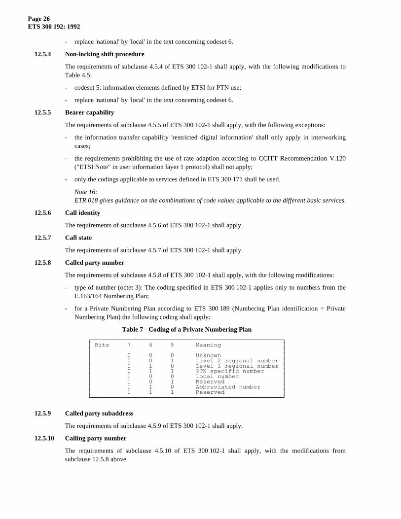
The requirements of subclause 4.5.8 of ETS 300 102-1 shall apply, with the following modifications:
- type of number (octet 3): The coding specified in ETS 300 102-1 applies only to numbers from theE.163/164 Numbering Plan;
- for a Private Numbering Plan according to ETS 300 189 (Numbering Plan identification = PrivateNumbering Plan) the following coding shall apply:
Table 7 - Coding of a Private Numbering Plan
ÚÄÄÄÄÄÄÄÄÄÄÄÄÄÄÄÄÄÄÄÄÄÄÄÄÄÄÄÄÄÄÄÄÄÄÄÄÄÄÄÄÄÄÄÄÄÄÄÄÄÄÄÄÄ¿³ Bits 7 6 5 Meaning ³³ ³³ 0 0 0 Unknown ³³ 0 0 1 Level 2 regional number ³³ 0 1 0 Level 1 regional number ³³ 0 1 1 PTN specific number ³³ 1 0 0 Local number ³³ 1 0 1 Reserved ³³ 1 1 0 Abbreviated number ³³ 1 1 1 Reserved ³ÀÄÄÄÄÄÄÄÄÄÄÄÄÄÄÄÄÄÄÄÄÄÄÄÄÄÄÄÄÄÄÄÄÄÄÄÄÄÄÄÄÄÄÄÄÄÄÄÄÄÄÄÄÄÙ
12.5.9 Called party subaddress
The requirements of subclause 4.5.9 of ETS 300 102-1 shall apply.
12.5.10 Calling party number
The requirements of subclause 4.5.10 of ETS 300 102-1 shall apply, with the modifications fromsubclause 12.5.8 above.

Page 27ETS 300 192: 1992
12.5.11 Calling party subaddress
The requirements of subclause 4.5.11 of ETS 300 102-1 shall apply.
12.5.12 Cause
The requirements of subclause 4.5.12 of ETS 300 102-1 shall apply, with the following qualifications:
- the Cause information element shall not appear more than once in a message;
- all values in the range 1 to 127 shall be accepted as valid cause values;
- any suitable cause value may be chosen from ETS 300 102-1, Table 4.13 except where the proceduresof this standard explicitly specify certain cause values, in which case those values shall be used;
- ETSI-specific cause values, encoded using coding standard '10', shall not apply.
Note 17:Refer to Annex B for information on the use of cause values.
12.5.13 Channel identification
The requirements of subclause 4.5.13 of ETS 300 102-1 shall apply, with the following restrictions:
- channel type (octet 3.2): Only the value 'B-channel units' shall be used (Bits 4 to 1 set to 0011);
- Note 4 of ETS 300 102-1 Figure 4.20 (optional repetition of octet 3.3) shall not apply.
Note 18:Refer to Annex H of ETS 300 102-1 for examples of the encoding of the Channel identificationinformation element.
12.5.14 Connected number
The purpose of the Connected number information element is to indicate which number is connected to acall. The connected number may be different from the called party number because of changes (e.g. callredirection, transfer) during the lifetime of the call.
The Connected number information element is coded as shown in figure 3. The coding of octets 3, 3a and4 shall follow the rules of subclause 4.5.10 of ETS 300 102-1, with the modifications from subclause12.5.8 above.
8 7 6 5 4 3 2 1ÚÄÄÄÄÄÄÄÂÄÄÄÄÄÄÄÄÄÄÄÄÄÄÄÄÄÄÄÄÄÄÄÄÄÄÄÄÄÄÄÄÄÄÄÄÄÄÄÄÄÄÄÄÄÄÄÄÄÄÄÄÄÄÄ¿³ ³ Connected number information element identifier ³³ 0 ³ 1 0 0 1 1 0 0 ³ Octet 1ÃÄÄÄÄÄÄÄÁÄÄÄÄÄÄÄÄÄÄÄÄÄÄÄÄÄÄÄÄÄÄÄÄÄÄÄÄÄÄÄÄÄÄÄÄÄÄÄÄÄÄÄÄÄÄÄÄÄÄÄÄÄÄÄ´³ Length of connected number information ³ Octet 2ÃÄÄÄÄÄÄÄÂÄÄÄÄÄÄÄÄÄÄÄÄÄÄÄÄÄÄÄÄÄÄÄÂÄÄÄÄÄÄÄÄÄÄÄÄÄÄÄÄÄÄÄÄÄÄÄÄÄÄÄÄÄÄÄ´³ 0/1 ³ Type of number ³ Numbering plan identification ³ Octet 3³ ext ³ ³ ³ÃÄÄÄÄÄÄÄÅÄÄÄÄÄÄÄÄÄÄÄÄÄÄÄÂÄÄÄÄÄÄÄÁÄÄÄÄÄÄÄÄÄÄÄÄÄÄÄÂÄÄÄÄÄÄÄÄÄÄÄÄÄÄÄ´³ 1 ³ Presentation ³ 0 0 0 ³ Screening ³ Octet 3a*)³ ext ³ Indicator ³ spare ³ Indicator ³ÃÄÄÄÄÄÄÄÅÄÄÄÄÄÄÄÄÄÄÄÄÄÄÄÁÄÄÄÄÄÄÄÄÄÄÄÄÄÄÄÄÄÄÄÄÄÄÄÁÄÄÄÄÄÄÄÄÄÄÄÄÄÄÄ´³ 0 ³ ³ Octet 4³ spare ³ Number digits ³ (repeated)ÀÄÄÄÄÄÄÄÁÄÄÄÄÄÄÄÄÄÄÄÄÄÄÄÄÄÄÄÄÄÄÄÄÄÄÄÄÄÄÄÄÄÄÄÄÄÄÄÄÄÄÄÄÄÄÄÄÄÄÄÄÄÄÄÙ
* This octet is optional
Figure 3 - Connected number information element
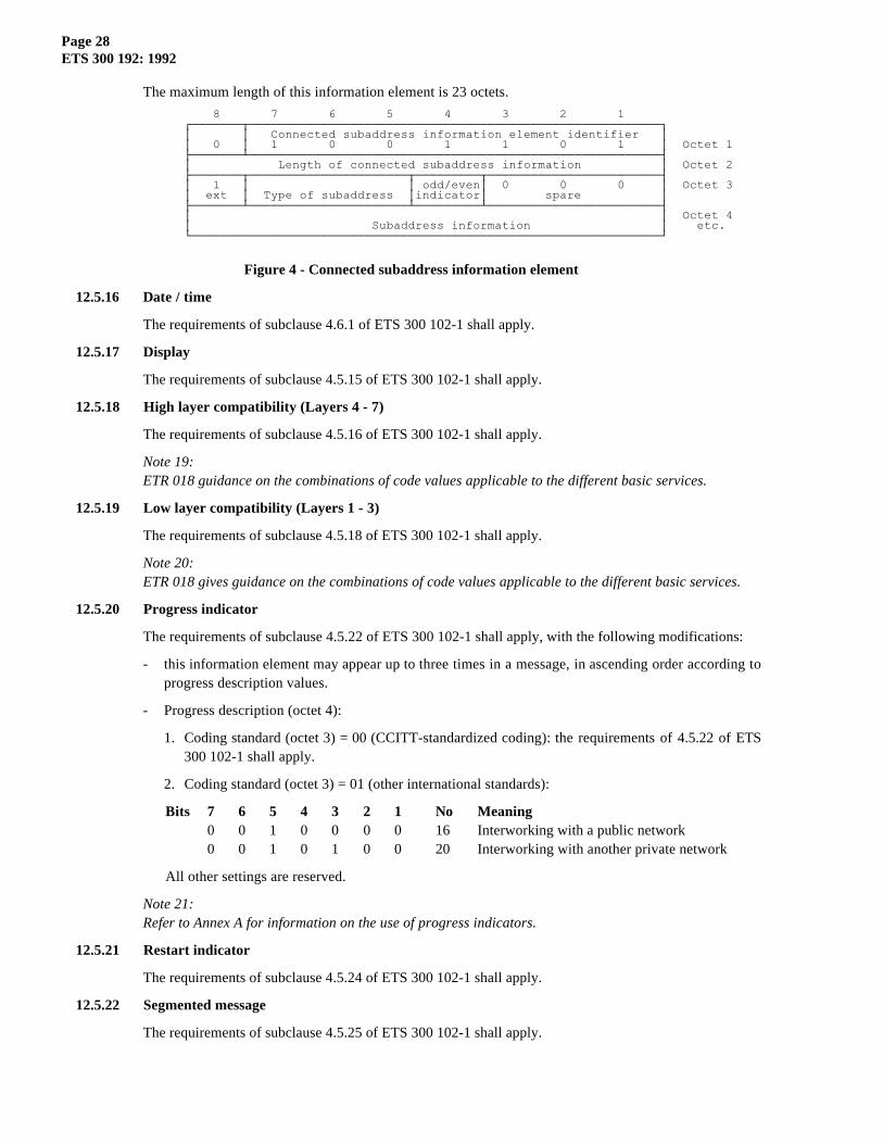
12.5.15 Connected subaddress
The purpose of the Connected subaddress information element is to identify the subaddress of theconnected party of a call. The Connected subaddress may be different from the called party subaddressbecause of changes (e.g. call redirections, transfer) during the lifetime of the call.
The Connected subaddress information element is coded as shown in figure 4. The coding of octets 3, 4,etc. shall follow the rules of subclause 4.5.11 of ETS 300 102-1.
Page 28ETS 300 192: 1992
The maximum length of this information element is 23 octets.
8 7 6 5 4 3 2 1ÚÄÄÄÄÄÄÄÂÄÄÄÄÄÄÄÄÄÄÄÄÄÄÄÄÄÄÄÄÄÄÄÄÄÄÄÄÄÄÄÄÄÄÄÄÄÄÄÄÄÄÄÄÄÄÄÄÄÄÄÄÄÄÄÄÄ¿³ ³ Connected subaddress information element identifier ³³ 0 ³ 1 0 0 1 1 0 1 ³ Octet 1ÃÄÄÄÄÄÄÄÁÄÄÄÄÄÄÄÄÄÄÄÄÄÄÄÄÄÄÄÄÄÄÄÄÄÄÄÄÄÄÄÄÄÄÄÄÄÄÄÄÄÄÄÄÄÄÄÄÄÄÄÄÄÄÄÄÄ´³ Length of connected subaddress information ³ Octet 2ÃÄÄÄÄÄÄÄÂÄÄÄÄÄÄÄÄÄÄÄÄÄÄÄÄÄÄÄÄÄÄÂÄÄÄÄÄÄÄÄÄÂÄÄÄÄÄÄÄÄÄÄÄÄÄÄÄÄÄÄÄÄÄÄÄÄ´³ 1 ³ ³ odd/even³ 0 0 0 ³ Octet 3³ ext ³ Type of subaddress ³indicator³ spare ³ÃÄÄÄÄÄÄÄÁÄÄÄÄÄÄÄÄÄÄÄÄÄÄÄÄÄÄÄÄÄÄÁÄÄÄÄÄÄÄÄÄÁÄÄÄÄÄÄÄÄÄÄÄÄÄÄÄÄÄÄÄÄÄÄÄÄ´³ ³ Octet 4³ Subaddress information ³ etc.ÀÄÄÄÄÄÄÄÄÄÄÄÄÄÄÄÄÄÄÄÄÄÄÄÄÄÄÄÄÄÄÄÄÄÄÄÄÄÄÄÄÄÄÄÄÄÄÄÄÄÄÄÄÄÄÄÄÄÄÄÄÄÄÄÄÄÙ
Figure 4 - Connected subaddress information element
12.5.16 Date / time
The requirements of subclause 4.6.1 of ETS 300 102-1 shall apply.
12.5.17 Display
The requirements of subclause 4.5.15 of ETS 300 102-1 shall apply.
12.5.18 High layer compatibility (Layers 4 - 7)
The requirements of subclause 4.5.16 of ETS 300 102-1 shall apply.
Note 19:ETR 018 guidance on the combinations of code values applicable to the different basic services.
12.5.19 Low layer compatibility (Layers 1 - 3)
The requirements of subclause 4.5.18 of ETS 300 102-1 shall apply.
Note 20:ETR 018 gives guidance on the combinations of code values applicable to the different basic services.
12.5.20 Progress indicator
The requirements of subclause 4.5.22 of ETS 300 102-1 shall apply, with the following modifications:
- this information element may appear up to three times in a message, in ascending order according toprogress description values.
- Progress description (octet 4):
1. Coding standard (octet 3) = 00 (CCITT-standardized coding): the requirements of 4.5.22 of ETS300 102-1 shall apply.
2. Coding standard (octet 3) = 01 (other international standards):
Bits 7 6 5 4 3 2 1 No Meaning0 0 1 0 0 0 0 16 Interworking with a public network0 0 1 0 1 0 0 20 Interworking with another private network
All other settings are reserved.
Note 21:Refer to Annex A for information on the use of progress indicators.
12.5.21 Restart indicator
The requirements of subclause 4.5.24 of ETS 300 102-1 shall apply.
12.5.22 Segmented message
The requirements of subclause 4.5.25 of ETS 300 102-1 shall apply.
Page 29ETS 300 192: 1992
12.5.23 Sending complete
The requirements of subclause 4.5.26 of ETS 300 102-1 shall apply.
12.6 Information elements of codeset 5
Codeset 5 contains information elements defined by ETSI, in addition to those specified inCCITT Recommendation Q.931.
In general the coding rules defined for codeset 0 apply also to codeset 5.
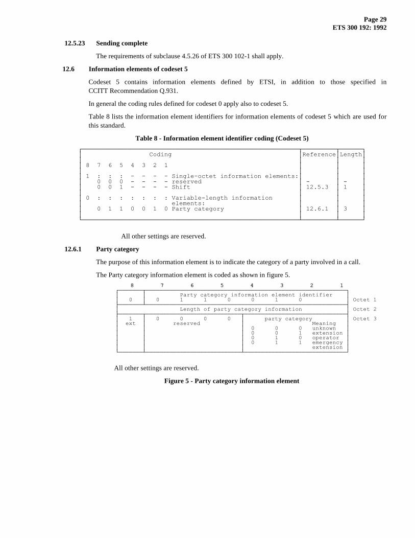
Table 8 lists the information element identifiers for information elements of codeset 5 which are used forthis standard.
Table 8 - Information element identifier coding (Codeset 5)
ÚÄÄÄÄÄÄÄÄÄÄÄÄÄÄÄÄÄÄÄÄÄÄÄÄÄÄÄÄÄÄÄÄÄÄÄÄÄÄÄÄÄÄÄÄÄÄÄÄÄÄÄÄÄÄÄÄÄÄÂÄÄÄÄÄÄÄÄÄÂÄÄÄÄÄÄ¿³ Coding ³Reference³Length³³ ³ ³ ³³ 8 7 6 5 4 3 2 1 ³ ³ ³³ ³ ³ ³³ 1 : : : - - - - Single-octet information elements:³ ³ ³³ 0 0 0 - - - - reserved ³ - ³ - ³³ 0 0 1 - - - - Shift ³ 12.5.3 ³ 1 ³³ ³ ³ ³³ 0 : : : : : : : Variable-length information ³ ³ ³³ elements: ³ ³ ³³ 0 1 1 0 0 1 0 Party category ³ 12.6.1 ³ 3 ³³ ³ ³ ³ÀÄÄÄÄÄÄÄÄÄÄÄÄÄÄÄÄÄÄÄÄÄÄÄÄÄÄÄÄÄÄÄÄÄÄÄÄÄÄÄÄÄÄÄÄÄÄÄÄÄÄÄÄÄÄÄÄÄÄÁÄÄÄÄÄÄÄÄÄÁÄÄÄÄÄÄÙ
All other settings are reserved.
12.6.1 Party category
The purpose of this information element is to indicate the category of a party involved in a call.
The Party category information element is coded as shown in figure 5.
8 7 6 5 4 3 2 1 8 7 6 5 4 3 2 1
ÚÄÄÄÄÄÄÄÂÄÄÄÄÄÄÄÄÄÄÄÄÄÄÄÄÄÄÄÄÄÄÄÄÄÄÄÄÄÄÄÄÄÄÄÄÄÄÄÄÄÄÄÄÄÄÄÄÄÄÄÄÄÄÄÄÄÄÄ¿³ ³ Party category information element identifier ³³ 0 ³ 0 1 1 0 0 1 0 ³ Octet 1ÃÄÄÄÄÄÄÄÁÄÄÄÄÄÄÄÄÄÄÄÄÄÄÄÄÄÄÄÄÄÄÄÄÄÄÄÄÄÄÄÄÄÄÄÄÄÄÄÄÄÄÄÄÄÄÄÄÄÄÄÄÄÄÄÄÄÄÄ´³ Length of party category information ³ Octet 2ÃÄÄÄÄÄÄÄÂÄÄÄÄÄÄÄÄÄÄÄÄÄÄÄÄÄÄÄÄÄÄÄÄÄÄÄÄÂÄÄÄÄÄÄÄÄÄÄÄÄÄÄÄÄÄÄÄÄÄÄÄÄÄÄÄÄÄÄ´³ 1 ³ 0 0 0 0 ³ party category ³ Octet 3³ ext ³ reserved ³ Meaning ³³ ³ ³ 0 0 0 unknown ³³ ³ ³ 0 0 1 extension ³³ ³ ³ 0 1 0 operator ³³ ³ ³ 0 1 1 emergency ³³ ³ ³ extension ³ÀÄÄÄÄÄÄÄÁÄÄÄÄÄÄÄÄÄÄÄÄÄÄÄÄÄÄÄÄÄÄÄÄÄÄÄÄÁÄÄÄÄÄÄÄÄÄÄÄÄÄÄÄÄÄÄÄÄÄÄÄÄÄÄÄÄÄÄÙ
All other settings are reserved.
Figure 5 - Party category information element

Page 30ETS 300 192: 1992
Annex A (informative): Use of progress indicators
- Progress description 1 indicates that interworking with a non-ISDN has occured within the network or networkswhich the call has traversed.
- Progress description 2 indicates that the destination TE is non-ISDN equipment.
- Progress description 3 indicates that the origination TE is non-ISDN equipment.
- Progress description 4 indicates that a call which had left the ISDN has returned at the same point it had left due toredirection within the non-ISDN. This progress indicator would be employed if a progress indicator No. 1 "call isnot end-to-end ISDN" had been delivered to the calling user before.
- The use of progress description 8 is described in Clause 8.
- Progress description 16 indicates that the call comes from or goes to the public ISDN.
- Progress description 20 indicates that the call comes from or goes to a private network other than the local PTN.

Page 31ETS 300 192: 1992
Annex B (informative): Use of cause values
B.1 Definition of cause values
For a definition of cause values refer to ETS 300 102-1 Annex G.
B.2 Use of causes for busy conditions
Based on the scenario of figure B.1 with an assumed call establishment attempt from 'A' towards 'D', table B.1below summarizes how causes No. 17 "user busy", 34 "no channel available" and 44 "requested channel notavailable" are to be used. Busy conditions encountered elsewhere along the call path are outside the scope ofthis standard (they are for instance dealt with by QSIG procedures).
For the case of interworking with a public ISDN, refer to ETS 300 102-1 Annex J.
A B C D
TE PTNX PTNX TE
S Q Q S
Figure B.1 - Scenario for busy cases
Table B.1 - Cause and location values for busy conditions
ÚÄÄÄÄÄÄÄÄÄÄÄÄÄÄÄÄÄÄÂÄÄÄÄÄÄÄÄÄÄÄÄÄÂÄÄÄÄÄÄÄÄÄÄÄÄÄÄÄÄÄÄÄÂÄÄÄÄÄÄÄÄÄÄÄÄÄÄÄÄÄÄÄÄÄÄÄÄÄÄÄÄÄ¿³ Location of Busy ³ Cause value ³ Original location ³ Location reported to user A ³ÃÄÄÄÄÄÄÄÄÄÄÄÄÄÄÄÄÄÄÅÄÄÄÄÄÄÄÄÄÄÄÄÄÅÄÄÄÄÄÄÄÄÄÄÄÄÄÄÄÄÄÄÄÅÄÄÄÄÄÄÄÄÄÄÄÄÄÄÄÄÄÄÄÄÄÄÄÄÄÄÄÄÄ´³ B Incoming side ³ 34 or 44 ³ local PTN ³ local PTN ³ÃÄÄÄÄÄÄÄÄÄÄÄÄÄÄÄÄÄÄÅÄÄÄÄÄÄÄÄÄÄÄÄÄÅÄÄÄÄÄÄÄÄÄÄÄÄÄÄÄÄÄÄÄÅÄÄÄÄÄÄÄÄÄÄÄÄÄÄÄÄÄÄÄÄÄÄÄÄÄÄÄÄÄ´³ B Outgoing side ³ 34 or 44 ³ local PTN ³ local PTN ³ÃÄÄÄÄÄÄÄÄÄÄÄÄÄÄÄÄÄÄÅÄÄÄÄÄÄÄÄÄÄÄÄÄÅÄÄÄÄÄÄÄÄÄÄÄÄÄÄÄÄÄÄÄÅÄÄÄÄÄÄÄÄÄÄÄÄÄÄÄÄÄÄÄÄÄÄÄÄÄÄÄÄÄ´³ C Outgoing side ³ 17 ³ local PTN ³ remote PTN or local PTN ³ÃÄÄÄÄÄÄÄÄÄÄÄÄÄÄÄÄÄÄÅÄÄÄÄÄÄÄÄÄÄÄÄÄÅÄÄÄÄÄÄÄÄÄÄÄÄÄÄÄÄÄÄÄÅÄÄÄÄÄÄÄÄÄÄÄÄÄÄÄÄÄÄÄÄÄÄÄÄÄÄÄÄÄ´³ D Incoming side ³ 34 or 44 ³ user ³ user ³ÃÄÄÄÄÄÄÄÄÄÄÄÄÄÄÄÄÄÄÅÄÄÄÄÄÄÄÄÄÄÄÄÄÅÄÄÄÄÄÄÄÄÄÄÄÄÄÄÄÄÄÄÄÅÄÄÄÄÄÄÄÄÄÄÄÄÄÄÄÄÄÄÄÄÄÄÄÄÄÄÄÄÄ´³ D call control ³ 17 ³ user ³ user ³ÀÄÄÄÄÄÄÄÄÄÄÄÄÄÄÄÄÄÄÁÄÄÄÄÄÄÄÄÄÄÄÄÄÁÄÄÄÄÄÄÄÄÄÄÄÄÄÄÄÄÄÄÄÁÄÄÄÄÄÄÄÄÄÄÄÄÄÄÄÄÄÄÄÄÄÄÄÄÄÄÄÄÄÙ

Page 32ETS 300 192: 1992
Annex C (informative): Examples of message sequences
The inter-PTNX signalling is not shown in detail in the following examples.
C.1 En-bloc sending
C.1.1 Successful call setup
Figure C.1 shows an example of the message sequences across the user-network interfaces at A and at Bwhen a call is initiated from TE A to TE B (which is free) and the called party number in the SETUPmessage to PTNX A is complete.
cr1, cr2 ... Call references
Figure C.1 - En-bloc sending, successful call
C.1.2 Unsuccessful call setup
Figure C.2 shows an example of the message sequences across the user-network interfaces at A and at Bwhen a call is initiated from TE A to TE B (which is busy) and the called party number in the SETUPmessage to PTNX A is complete.
cr1, cr2 ... Call references, cs ... Cause
Figure C.2 - En-bloc sending, unsuccessful call
Page 33ETS 300 192: 1992
C.2 Overlap sending
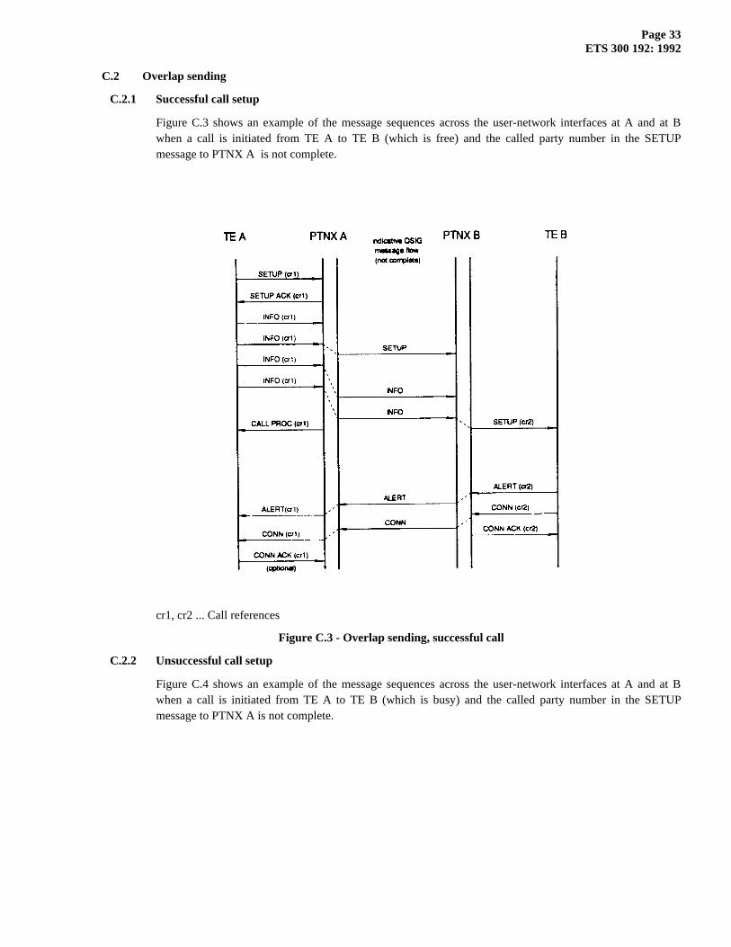
C.2.1 Successful call setup
Figure C.3 shows an example of the message sequences across the user-network interfaces at A and at Bwhen a call is initiated from TE A to TE B (which is free) and the called party number in the SETUPmessage to PTNX A is not complete.
cr1, cr2 ... Call references
Figure C.3 - Overlap sending, successful call
C.2.2 Unsuccessful call setup
Figure C.4 shows an example of the message sequences across the user-network interfaces at A and at Bwhen a call is initiated from TE A to TE B (which is busy) and the called party number in the SETUPmessage to PTNX A is not complete.

Page 34ETS 300 192: 1992
cr1, cr2 ... Call references, cs ... Cause
Figure C.4 - Overlap sending, unsuccessful call
C.3 Call clearing
Figure C.5 shows an example of normal call clearing from the active state, initiated by TE A.
cr1, cr2 ... Call references, cs ... Cause
Figure C.5 - Normal call clearing
Page 35ETS 300 192: 1992
Annex D (informative): Manufacturer specific information
This standard permits the inclusion in messages of non-standardized information which is specific to a particularmanufacturer, a particular design of equipment, a particular network, etc.. This information is known as Manufacturer-Specific Information (MSI).
The exchange of MSI across a user-network interface may be achieved by means of information elements of codeset 6or 7. The error procedures of subclause 7.3 will apply in the event of an information element being received and notrecognized by a terminal or PTNX. Note that ambiguity may arise when two items of equipment use the sameinformation element identifier for different purposes.
A general purpose method of conveying MSI is by means of the Facility information element specified forsupplementary services in another standard. This provides a transparent means of conveying information between aterminal and a PTNX which is not necessarily the terminal's local PTNX. It uses internationally recognized ObjectIdentifiers to avoid ambiguity.

Page 36ETS 300 192: 1992
Annex E (informative): Bibliography
ETS 300 102-2 Integrated Services Digital Network (ISDN); User-network interface layer 3,Specifications for basic call control, Specification Description Language (SDL) diagrams(1990).
ETS 300 055 Integrated Services Digital Network (ISDN); Terminal Portability (TP) supplementaryservice, Digital Subscriber Signalling System No. one (DSS1) protocol (1991).
ETR-018 Integrated Services Digital Network (ISDN); Application of the BC-, HLC-, LLC-information elements by terminals supporting ISDN services.

Page 37ETS 300 192: 1992
Annex F (informative): Terminal interchangeability
Terminals can be designed that will be compatible with both public ISDNs offering interfaces conforming to ETS300 102-1 and PTNs offering interfaces conforming to this standard.

Page 38ETS 300 192: 1992
History
Document history
December 1992 First Edition
February 1996 Converted into Adobe Acrobat Portable Document Format (PDF)