eurocontrol tender no 10-110288-e - pilot study evaluating ... · skyguide: carla thoma (project...
TRANSCRIPT

Project Document
EUROCONTROL Tender No 10-110288-E - Pilot Study Evaluating Guidance Material on the Provision of Terrain and Obstacle Data (TOD) in Accordance with ICAO Annex 15
Final Report
version/lang. 1.0 Rev.1 / E
status released
date of issue 2011-06-30 / Rev.1 2011-08-24
author/unit Skyguide: Carla Thoma (project leader), Roland Baumann, Andreas Lüscher
SIA: Stéphane Dubet, Stéphane Pelle
FOCA: Markus Luginbühl, Daniela Nowak
DGAC: Cédric Tedesco
ITV Geomatik AG: Ruedi Schneeberger
owner/unit Skyguide: Baumann Roland, Andreas Lüscher
file ECTL Tender No 10-110288-E - eTOD Pilot Study_v1.0 Rev.1 - public.doc
pages 68
classification public
distribution to: EUROCONTROL, Roland Rawlings (Chairman TOD WG)
cc: -
annexes
abstract The implementation of the TOD requirements as stated by ICAO Annex 15 requires the collection and survey of a relatively large amount of terrain and obstacle data. In order to support Member States in the production and management of this data, EUROCONTROL has developed Guidance Material in the form of the TOD Manual. This Pilot Study evaluated the Manual in view of putting eTOD into practice.
This report summarises the tasks performed and lists findings and recommendations.
legal notice ©2011 The European Organisation for the Safety of Air Navigation (EUROCONTROL). All rights reserved. This document is published by EUROCONTROL for information purposes. It may be copied in whole or in part, provided that EUROCONTROL is mentioned as the source and to the extent justified by non-commercial use (not for sale). The information contained in this document may not be modified without prior written permission from EUROCONTROL. The use of the document is at the user’s sole risk and responsibility. EUROCONTROL expressly disclaims any and all warranties with respect to any content within the document, express or implied.

EUROCONTROL Tender No 10-110288-E Pilot Study Evaluating Guidance Material TOD version: 1.0 Rev.1 / status: released Final Report classification: public
Table of contents Page
1 History of Changes and Approval ...........................................................5
2 Management Summary ............................................................................6
3 Introduction...............................................................................................8
3.1 Purpose...............................................................................................................................8 3.2 Scope ..................................................................................................................................8 3.3 Approach ............................................................................................................................8 3.4 Involved Parties .................................................................................................................9 3.5 Reference Material ...........................................................................................................10 3.6 Terms and Abbreviations................................................................................................10
4 Part 1: Work Packages ...........................................................................13
4.1 WP1: Obstacle Management Process............................................................................13 4.1.1 Introduction ...................................................................................................................13 4.1.2 France...........................................................................................................................13
4.1.3 Switzerland ...................................................................................................................14 4.1.3.1 Existing authorisation process ......................................................................................14
4.1.3.2 New with ICAO Annex 15 .............................................................................................14
4.1.4 Comparison...................................................................................................................15 4.2 WP2: Bilateral Contracts .................................................................................................16 4.2.1 Introduction ...................................................................................................................16 4.2.2 Issues to be clarified within bilateral contracts .............................................................17 4.3 WP3: Obstacle Survey.....................................................................................................17 4.3.1 Introduction ...................................................................................................................17 4.3.2 Base Data .....................................................................................................................17 4.3.3 Airport Surveys .............................................................................................................18 4.3.3.1 Airport Basel-Mulhouse (LFSB) ....................................................................................18
4.3.3.1.1 Context and status France............................................................................................18 4.3.3.1.2 General specifications established by SIA with support of IGN ...................................18 4.3.3.1.3 Data collection ..............................................................................................................20 4.3.3.1.4 Data capture rules.........................................................................................................25 4.3.3.1.5 Captured obstacles.......................................................................................................27 4.3.3.1.6 LIDAR data ...................................................................................................................31
4.3.3.2 Airport Geneva (LSGG) ................................................................................................32
4.3.3.2.1 Introduction ...................................................................................................................32 4.3.3.2.2 Pilot Study perimeter.....................................................................................................32 4.3.3.2.3 Data capture specifications...........................................................................................33 4.3.3.2.4 Data collection with photogrammetry............................................................................33 4.3.3.2.5 Orthophoto ....................................................................................................................34 4.3.3.2.6 Obstacle Data Collection Surfaces (ODCS) .................................................................35 4.3.3.2.7 Data collection ..............................................................................................................36 4.3.3.2.8 Data model....................................................................................................................38 4.3.3.2.9 Results ..........................................................................................................................40
date of issue: 2011-06-30 / REV.1 2011-08-24, skyguide 2/68

EUROCONTROL Tender No 10-110288-E Pilot Study Evaluating Guidance Material TOD version: 1.0 Rev.1 / status: released Final Report classification: public
4.3.3.2.10 Quality checks and reports ...........................................................................................41 4.3.3.2.11 Additional value: Airport Zurich (LSZH) ........................................................................41 4.4 WP4: Digital Terrain Model (DTM) ..................................................................................43 4.4.1 Introduction ...................................................................................................................43 4.4.2 Basic requirements and data preparation.....................................................................43 4.4.3 DTM data set France ....................................................................................................43 4.4.3.1 Area 1 ...........................................................................................................................43
4.4.3.2 Area 2 ...........................................................................................................................44
4.4.4 DTM data set Switzerland.............................................................................................44 4.4.5 DTM data set from third party for Area 2 ......................................................................44 4.4.6 Analysis.........................................................................................................................45 4.4.7 Results ..........................................................................................................................46 4.4.8 Data exchange format for terrain data..........................................................................47
5 Part 2: Findings and Recommendations ..............................................48
5.1 Introduction ......................................................................................................................48 5.2 Institutional Issues ..........................................................................................................48 5.2.1 Coordinated flow of information in cross-border Area 2 ...............................................48 5.2.2 Bilateral agreements.....................................................................................................50 5.2.3 Borderline......................................................................................................................51 5.2.4 Harmonised Publication Process..................................................................................51 5.2.5 Considerations on costs for the implementation of eTOD............................................51 5.2.5.1 Technical specifications................................................................................................52
5.2.5.2 Configuration and topography of the aerodrome..........................................................52
5.2.5.3 Sharing cost ..................................................................................................................54
5.2.5.4 Case studies .................................................................................................................54
5.2.5.4.1 Airport Basel-Mulhouse (LFSB) ....................................................................................54 5.2.5.4.2 Airport Geneva (LSGG) ................................................................................................56 5.2.5.4.3 Fictitious example with LIDAR......................................................................................57 5.2.5.5 Conclusions and further considerations........................................................................57
5.3 Technical Issues ..............................................................................................................58 5.3.1 Comparison of Annex 4/14/15 ......................................................................................58 5.3.2 Interpretation of definition of Area 2b............................................................................58 5.3.3 Segmentation of buildings ............................................................................................58 5.3.4 Segmentation of vegetation ..........................................................................................59 5.3.5 Detectability of thin objects ...........................................................................................59 5.3.6 Obstacle attribute "Height"............................................................................................60 5.3.7 Test cases for verification and validation......................................................................61 5.3.8 Data Product Specifications (DPS)...............................................................................62 5.3.9 Coverage of area along the borderline .........................................................................62 5.3.10 Merging of DTM data sets ............................................................................................63 5.3.11 DTM with maximum values <> DTM with mean values................................................64 5.3.12 Considerations on DTM data sets ................................................................................65 5.3.13 Data exchange formats.................................................................................................65 5.3.13.1 AIXM .............................................................................................................................65
5.3.13.2 TIXM .............................................................................................................................66
date of issue: 2011-06-30 / REV.1 2011-08-24, skyguide 3/68

EUROCONTROL Tender No 10-110288-E Pilot Study Evaluating Guidance Material TOD version: 1.0 Rev.1 / status: released Final Report classification: public
6 Annex.......................................................................................................67
6.1 Project Schedule..............................................................................................................67
date of issue: 2011-06-30 / REV.1 2011-08-24, skyguide 4/68

EUROCONTROL Tender No 10-110288-E Pilot Study Evaluating Guidance Material TOD version: 1.0 Rev.1 / status: released Final Report classification: public
1 History of Changes and Approval
Changes and Reviews
Version Status Date of issue Author Details
1.0 Released 30.06.2011 Carla Thoma, skyguide
Released by:
Skyguide: Carla Thoma Roland Baumann Andreas Lüscher
SIA: Stéphane Dubet Stéphane Pelle
FOCA: Markus Luginbühl Daniela Nowak
DGAC: Cédric Tedesco
ITV Geomatik AG: Ruedi Schneeberger
1.0 Rev.1
Released 24.08.2011 Carla Thoma, skyguide
Legal notice adapted
Contract Approval
Version Status Approval Date Approver
1.0 Released 30.06.2011 Roland Baumann, skyguide Andreas Lüscher, skyguide
1.0 Rev.1
Released 24.08.2011 Roland Baumann, skyguide Andreas Lüscher, skyguide
date of issue: 2011-06-30 / REV.1 2011-08-24, skyguide 5/68

EUROCONTROL Tender No 10-110288-E Pilot Study Evaluating Guidance Material TOD version: 1.0 Rev.1 / status: released Final Report classification: public
2 Management Summary
The provisions regarding Terrain and Obstacle Data (TOD), as introduced by ICAO in Amendment 33 to Annex 15, represent a significant challenge as far as the actual implementation is concerned. EUROCONTROL established the TOD Working Group (WG) to support the implementation of eTOD in the European Region in a harmonised manner. In collaboration with the TOD WG, EUROCONTROL supported the development of appropriate Guidance Material, which was released in a first version in June 2010.
In order to further consolidate this TOD Manual EUROCONTROL commissioned a feasibility study. EUROCONTROL selected a consortium of ANSPs and Regulators of France and Switzerland under the lead of the Swiss air navigation service provider Skyguide with the objective to evaluate the applicability of the TOD Manual in real cases.
France as well as Switzerland had already launched their eTOD implementation projects some years ago and exchanged implementation aspects and results including cross-border challenges. Based on this experience both countries offered to contribute the results from their national implementation projects for the airports Basel-Mulhouse (France) and Geneva (Switzerland), both situated close to the borders. In addition Switzerland offered the results of the airport Zurich (in the vicinity of the Swiss/German border) for consideration.
To be able to compare different technologies, photogrammetry was used for the airports Basel-Mulhouse and Geneva whereas LIDAR (LIght Detection And Ranging) was used for the airport Zurich. During the study obstacles were collected within defined parts of Area 2. Digital Terrain Data (DTM) for Area 1 and 2 was obtained from the two national Geodetic Institutes based on a set of requirements elaborated by the Pilot Study team.
Furthermore institutional aspects were addressed in the Pilot Study related to topics such as bilateral agreements and obstacle management processes in each country and how these could be coordinated.
During the Pilot Study several technical and institutional aspects were identified, some of them requiring additional considerations and provisions going beyond the current version of the TOD Manual:
Institutional Issues:
need for a coordinated flow of information regarding obstacle data in cross-border Area 2;
need for organisational and technical bilateral agreements (for Area 2) between all responsible parties involved;
need for refinement of the implementation costs and the cost recovery mechanisms.
Technical Issues:
required comparison of ICAO Annex 4, 14 and 15 in regard to establish an all-encompassing limitation surface;
re-evaluation of the segmentation definitions regarding vegetation and buildings supporting operational benefits;
date of issue: 2011-06-30 / REV.1 2011-08-24, skyguide 6/68

EUROCONTROL Tender No 10-110288-E Pilot Study Evaluating Guidance Material TOD version: 1.0 Rev.1 / status: released Final Report classification: public
refinement of the national DTMs along the borderlines with the Geodetic Institutes, as appropriate.
One of the goals of the study was to get an understanding of the cost involved for the implementation of eTOD. The study provides details regarding costs and identifies the main cost driving factors (surrounding topography - mainly in the Area 2, obstacle density and applied survey techniques). The study confirms that cost can significantly vary depending on a number of factors including the actual structures within a State, roles and responsibilities of the involved parties within the State, as well as the financial and economical situation of a State. The figure provided in the TOD Manual Draft 1.0 could not be verified and should be considered as being too low in many cases.
The results of the Pilot Study lead to the conclusion that the available Draft TOD Manual can to a large extent support States during implementation. Most issues are covered in a detailed manner. Further elements developed during the Pilot Study may support the actual and practical TOD implementation by States. Nevertheless, although the available Draft TOD Manual can be considered quite comprehensive some issues stressed in this report require further discussion. The partners of the eTOD Pilot Study propose that these issues should be taken on board by the future TOD WG which shall have an increased focus on implementation.
On behalf of France and Switzerland all contributing parties of the eTOD Pilot Study would like to thank EUROCONTROL for having been given the opportunity to investigate the cross-border issues with two concrete aerodromes. All parties acknowledge that the preparation of the TOD Manual by EUROCONTROL is considered an important contribution towards supporting States in the implementation of eTOD. With the eTOD Pilot Study EUROCONTROL has enabled to address and identify the critical issues in respect to the practical implementation and share the results with all other States in Europe as well as with ICAO at the global level.
date of issue: 2011-06-30 / REV.1 2011-08-24, skyguide 7/68

EUROCONTROL Tender No 10-110288-E Pilot Study Evaluating Guidance Material TOD version: 1.0 Rev.1 / status: released Final Report classification: public
3 Introduction
3.1 Purpose
The implementation of the TOD requirements as stated by ICAO Annex 15 requires the collection and survey of a relatively large amount of terrain and obstacle data. In order to support Member States in the production and management of this data, EUROCONTROL has developed Guidance Material in the form of the TOD Manual (Draft Version 1.0, edition date 7th June 2010). In parallel to the consultation period of the Manual, EUROCONTROL commissioned a Pilot Study in order to evaluate the TOD Manual with respect to the practical experience gained from two aerodrome surveys executed. In the following, France and Switzerland agreed to fund the aerodrome surveys and to contribute to the EUROCONTROL Pilot Study. This document presents the findings elaborated during the Pilot Study.
The survey of inland aerodromes is fairly straight forward whereas the survey of aerodromes near the border of a State poses some difficulties in obtaining terrain and obstacle data from all organisations of the States involved. To find out what kind of issues arises for aerodromes with areas in more than one State, surveys for the two aerodromes Basel-Mulhouse (LFSB) and Geneva (LSGG) were performed within this Pilot Study. At the same time as the EUROCONTROL Pilot Study was progressing, Switzerland surveyed Zurich (LSZH) for the Swiss Pilot Study. Experiences made during that project could be integrated as well. The use of different survey technologies, such as photogrammetry and LIDAR (LIght Detection And Ranging), generated further benefit for the study.
In the first part, this project report summarises the tasks performed and, in the second part, lists all issues, which came up during the project. Most of the issues were discussed with EUROCONTROL during the project (Meetings: 21.07. and 21.10.2010). Wherever possible the project team elaborated recommendations. The recommendations are meant to help on one hand to improve the TOD Manual. On the other hand they should serve other States when implementing eTOD. Some issues, for which no recommendations could be given by the project team, will need further analysis by EUROCONTROL.
3.2 Scope
The scope of this project was to evaluate the TOD Manual in practice by performing surveys for two airports Basel-Mulhouse (LFSB) and Geneva (LSGG) by selecting representative areas allowing the evaluation of all aspects in the TOD Manual including cross-border issues. Organisational and technical issues in the implementation of eTOD for these aerodromes were carefully considered and analysed.
3.3 Approach
The tasks of the project were broken down in four Work Packages (WP), which were brought into a fairly ambitious schedule (see Chapter 6.1). Two of them dealt with institutional issues, the other two were concentrating on technical issues. A short description of the tasks done for each WP is given below:
WP1: Obstacle management processes Analysis of the obstacle management processes in Switzerland and France with a focus on the data exchange between ANSPs and Authorities for obstacles with regard to eTOD requirements. Determine where harmonisation between the countries is necessary.
date of issue: 2011-06-30 / REV.1 2011-08-24, skyguide 8/68

EUROCONTROL Tender No 10-110288-E Pilot Study Evaluating Guidance Material TOD version: 1.0 Rev.1 / status: released Final Report classification: public
WP2: Bilateral contracts Analysis of the requirements of organisational issues (responsibilities, notification procedures, data exchange, etc.) that need to be covered in bilateral agreements. Describe findings and recommendations.
WP3: Obstacle survey Analysis of the Guidance Material developed and provided by EUROCONTROL and comparison to national guidelines. Execution of the surveys for airports LSGG and LFSB based on the result of the before mentioned analysis and proof of concept of the guidelines. As Switzerland is performing a survey for LSZH at the same time as this Pilot Study is ongoing, the results out of this survey are included in the findings and recommendations.
WP4: DTM (Digital Terrain Model) Comparison of the different DTM of the two countries and identification of needs for harmonisation of the data set.
3.4 Involved Parties
The following parties contributed with their supporting and valuable experience to this Pilot Study:
skyguide skyguide provided the appropriate project management support to ensure that the required deliverables were submitted to EUROCONTROL according to the milestone planning given. Furthermore skyguide actively contributed with expertise in the analysis and compilation of the required deliverables.
DGAC DGAC contributed through survey of Basel-Mulhouse (LFSB), analysis of the results and proposition of best practices for cross-border issues. Particularly involved, the SIA participates directly in discussions and writing reports. It was also be the contact point to the French regulators (DGAC/DTA) and to various technical experts including those of the French National Geographic Institute (IGN). SIA took advantage of its commitment in international activities related to eTOD under the auspices of ICAO and EUROCAE, as well as its central role in RNAV procedure design for DSNA. SIA executed a specific survey of Basel-Mulhouse (LFSB) using photogrammetry for parts of Area 1, 2, 3 and 4. LIDAR data was acquired in Area 3 in addition to photogrammetric data. Furthermore SIA incorporated its findings out of the surveys done in Clermont-Ferrand (2007) and Toulouse-Blagnac (2009).
FOCA The Swiss Regulator performed obstacle and terrain surveys in the framework of the implementation of ICAO Annex 15, Chapter 10 (eTOD). These surveys were done for extracts of the Area 2 (a, b, c and d) of the two major international airports Geneva (LSGG) and Zurich (LSZH). An additional test survey is planned to be done in a mountainous Area 1 region in Central Switzerland. In this context, FOCA contributed to this study with results from LSGG survey to evaluate cross-border issues and technical aspects using photogrammetry. Out of the survey of LSZH, consolidated findings are provided. Additionally, the Swiss DTM data required is provided by FOCA through Swisstopo (the Swiss Geodetic Institute) in the context of the Swiss Pilot Study.
date of issue: 2011-06-30 / REV.1 2011-08-24, skyguide 9/68

EUROCONTROL Tender No 10-110288-E Pilot Study Evaluating Guidance Material TOD version: 1.0 Rev.1 / status: released Final Report classification: public
ITV Geomatik AG ITV Geomatik AG contributed to this study by supporting the project team in technical questions and project management, analysis of certain issues and writing reports.
3.5 Reference Material
The following documents have been taken into consideration for the elaboration or have been used as source of the present content:
Ref. Issuing Body Title Edition
1 ICAO Annex 15 – Aeronautical Information Services AMDT 36
2 EUROCONTROL Terrain and Obstacle Data Manual (TOD Manual) Draft 1.0, 07.06.2010
3 EUROCONTROL Terrain and Data Model Primer 0.5, 27.02.2009
3.6 Terms and Abbreviations Term/Abbreviation Description
AD Aerodrome
ADQ IR Aeronautical Data Quality Implementing Rule
AGL Above Ground Level
AIC Aeronautical Information Circular
AIM Aeronautical Information Management
AIP Aeronautical Information Publication
AIRM ATM Information Reference Model
AIXM Aeronautical Information Exchange Model
AMDT Amendment
ANSP Air Navigation Service Provider
ASL Above Sea Level
ATFM Air Traffic Flow Management
ATM Air Traffic Management
BKG Bundesamt für Kartographie und Geodäsie (Germany)
CAA Civil Aviation Authority
CAD Computer Aided Design
Cantonal Swiss administrative unit (canton)
CGIAR Consultative Group on International Agriculture Research
CH Switzerland
CH1903 Swiss Horizontal Reference System, 1903
CNS Communication, Navigation and Surveillance
DB Data Base
DEM Digital Elevation Model
DGAC Direction Générale de l'Aviation Civile
DPS Data Product Specifications
date of issue: 2011-06-30 / REV.1 2011-08-24, skyguide 10/68

EUROCONTROL Tender No 10-110288-E Pilot Study Evaluating Guidance Material TOD version: 1.0 Rev.1 / status: released Final Report classification: public
Term/Abbreviation Description
DSAC/IR Directions de la Sécurité de l'Aviation Civile/InterRegionales
DSM Digital Surface Model
DSNA Direction des Services de la Navigation Aérienne
DTA Direction du Transport Aérien
DTM Digital Terrain Model
DTS Data Transfer Specifications
DXF Drawing eXchange Format (Autodesk)
EGM96 Earth Gravitational Model 1996
ESRI Environmental Systems Research Institute
eTOD electronic Terrain and Obstacle data
EUROCAE European Organisation for Civil Aviation Equipment
F France
FABEC Functional Airspace Block Europe Central
FL Flight Level
FOCA Federal Office of Civil Aviation
GEN General
GIS Geographic Information System
GSD Ground Sampling Distance
GUID Globally Unique IDentifier
ICAO International Civil Aviation Organisation
IGN Institut Géographique National
IMU Inertial Measurement Unit
INTERLIS Data Exchange Format for GIS in Switzerland
LHN95 Swiss Height Reference System, 1995
LIDAR LIght Detection and Ranging
LN02 Swiss Height Reference System, 1902
LoA Letter of Agreement
LOD Level of Detail
LSFB Airport Basel-Mulhouse, F
LSGG Airport Geneva, CH
LSZH Airport Zurich, CH
LV95 Swiss Horizontal Reference System, 1995
MET Meteorological or meteorology
MSL Mean Sea Level
NGF Nivellement Général de la France
NOTAM Notice to airman
ODCS Obstacle Data Collection Surfaces
OLS Obstacle Limitation Surface
PANS-OPS Procedures for Air Navigation Services – Operations
date of issue: 2011-06-30 / REV.1 2011-08-24, skyguide 11/68

EUROCONTROL Tender No 10-110288-E Pilot Study Evaluating Guidance Material TOD version: 1.0 Rev.1 / status: released Final Report classification: public
Term/Abbreviation Description
RGF Réseau Géodésique Français
RNAV Area Navigation
RWY Runway
SESAR Single European Sky ATM Research
SIA Service de l'Information Aéronautique
SPOT Satellite Pour l’Observation de la Terre
SRTM Shuttle Radar Topography Mission
SW Software
SWIM System Wide Information Management
TIN Triangulated Irregular Network
TIXM Terrain Information Exchange Model
TMA Terminal control area
TOD Terrain and Obstacle Data
WG Working Group
WGS84 World Geodetic System
WP Work Package
date of issue: 2011-06-30 / REV.1 2011-08-24, skyguide 12/68

EUROCONTROL Tender No 10-110288-E Pilot Study Evaluating Guidance Material TOD version: 1.0 Rev.1 / status: released Final Report classification: public
4 Part 1: Work Packages
4.1 WP1: Obstacle Management Process
4.1.1 Introduction
The obstacle management process of each country was analysed and described (Chapter 4.1.2 and 4.1.3) in order to identify the harmonisation need between the countries France and Switzerland. The analysis of the obstacle management process in each country was done with a focus on the information and data exchange between ANSPs and Authorities. After the analysis in each country the description of the process was exchanged, compared and points of time for necessary interactions were identified (Chapter 4.1.4).
4.1.2 France
According to the French regulation, the relevant authorities will perform the necessary check whether a planned object will constitute an obstacle or not. The type of buildings that have to get this permission are fully defined in the French regulation. The owner is not responsible to determine whether a planned object change would constitute an obstacle or not. He just has to request the permission if it is required.
This notification is systematically made to the appropriate local planning authority (that is not an aviation or military body).
Impact on aviation/military activities is then taken into account through the following mechanisms:
Inside the limits of the OLS: According to the French regulation, all the aerodromes in France shall be protected by some Obstacle Limitation Surfaces (OLS). OLS are also defined around ground facilities. Those OLS are formally defined and known by the planning authorities that shall not grant any permission for obstacles penetrating those surfaces.
Beyond the limits of the OLS: Beyond the limits of the OLS, planned obstacles whose height exceeds 50 metres (100 metres inside a built-up area) shall be systematically submitted to the civil aviation and military authorities for authorisation. Practically, for those obstacles, the planning authorities pass the relevant information to the aviation and military authorities. The planning authorities are then advised if the obstacle has a negative impact on aviation or not. If the authorisation of the civil aviation or military authorities has not been granted, the construction of the obstacle is normally rejected by the planning authorities.
The obstacle owner shall notify the planning authorities on the start of the construction.
However, there is no requirement in the French regulation to forward this notification to the aviation / military authorities. Waiting for a change in the French regulation to solve this issue, in order to be able to know when the publication of the obstacle shall be originated, the aviation / military authorities generally try to put in place some local agreements with the planning authorities to have access to this notification.
Note: For each location in France, there are entities that are formally designed as being the civil aviation and military authorities competent for this location. For the civil aviation, those entities are regional entities of the DGAC and are called “DSAC/IR”.
date of issue: 2011-06-30 / REV.1 2011-08-24, skyguide 13/68

EUROCONTROL Tender No 10-110288-E Pilot Study Evaluating Guidance Material TOD version: 1.0 Rev.1 / status: released Final Report classification: public
Inspection of the construction can be performed by the planning authority but is not systematic.
4.1.3 Switzerland
4.1.3.1 Existing authorisation process
According to national law the obstacle owner notifies via the Cantonal Registration Office the FOCA of a planned obstacle, if it's intersecting an OLS according Annex 14 around an aerodrome or if its height exceeds 25 m (outside built-up area) or 60 m (inside a built-up area). The FOCA assesses the obstacle according ICAO Annex 14 and brings in the assessments and the comments and conditions of other organisations like the Air Force (25/60 m), PANS-OPS, etc. FOCA then issues a decree with conditions imposed to the obstacle owner.
The obstacle owner notifies the FOCA on the start of the construction. FOCA originates the publication of the obstacle and sets the object active in the database.
4.1.3.2 New with ICAO Annex 15
A new object will be surveyed by a surveyor. He checks, if the object is an obstacle according to Annex 15. If so, the surveyor delivers the surveyed coordinates of the obstacle to the central obstacle database. Skyguide will update all necessary publications (electronic obstacle data set, AIP and charts). If a planned version of the same object (out of the authorisation process described above) already exists in the database, skyguide will check if the surveyed coordinates of the built object is within a tolerance of the authorised position and height of the object. If the tolerance is exceeded, the case will be passed to FOCA for further actions.
date of issue: 2011-06-30 / REV.1 2011-08-24, skyguide 14/68

EUROCONTROL Tender No 10-110288-E Pilot Study Evaluating Guidance Material TOD version: 1.0 Rev.1 / status: released Final Report classification: public
4.1.4 Comparison
Process step France Switzerland
Obstacle notification The owner of the land shall request the permission of the appropriate local planning authority to build / extend / remove a structure that will become / is an obstacle (the type of buildings that have to get this permission are fully defined in the French regulation).
Planning authorities pass the relevant information to the aviation and military authorities if obstacle height exceeds 50 metres (100 metres inside a built-up area).
Owners of obstacles intersecting with OLS or higher than 25 m (outside built-up area) or (60 m inside a built-up area).
Assessment General assessment always made by the planning authority.
However, if obstacle height exceeds 50 metres (100 metres inside a built-up area), the planning authorities shall pass the relevant information to the civil aviation and military authorities in order to assess impact on aviation.
Civil aviation authorities supported by military authorities, PANS-OPS.
Permission Yes / Yes with conditions / No Yes / Yes with conditions / No
Publication The obstacle owner notifies the planning authorities on the start of the construction.
Even if there is no requirement in the French regulation to forward this notification to the aviation/military authorities, local agreements are generally put in place in order to be able to know when the publication of the obstacle shall be originated.
After notification of the beginning of the construction works by the owner.
Inspection Inspection of the construction can be performed by the planning authority but is not systematic.
Spot tests.
Obstacle survey (Annex 15) There is no specific requirement in the French regulation for the obstacle owner to perform a survey with all the necessary metadata for the aviation community.
Surveyor is responsible for a survey of all objects falling under Annex 15 Chapter 10.
date of issue: 2011-06-30 / REV.1 2011-08-24, skyguide 15/68

EUROCONTROL Tender No 10-110288-E Pilot Study Evaluating Guidance Material TOD version: 1.0 Rev.1 / status: released Final Report classification: public
Obstacle management processes in France and in Switzerland are quite similar, although the steps vary.
The main differences are:
There are different authorities involve for the assessment and issuing permission of obstacles in each country;
There is no regulation in France allocating the survey duty and cost to the obstacle owner;
The limitation height imposed by the Air Forces, which are lower in Switzerland than in France. This is not causing a cross-border issue, because these differences are only of national interests and do not need to be harmonised.
Note: The intention of the table above is to show the differences of the obstacle management process for France and Switzerland, which will have to be considered for the development and definition of a coordinated flow of information (see Chapter 5.2.1). The steps of the obstacle management process of each country were not assessed regarding advantages/disadvantages, since they are under the responsibility of each State.
4.2 WP2: Bilateral Contracts
4.2.1 Introduction
Annex 15, Chapter 3 states:
“3.1.5 An aeronautical information service shall promptly make available to the aeronautical information services of other States any information/data necessary for the safety, regularity or efficiency of air navigation required by them, to enable them to comply with 3.1.6 below.
3.1.6 An aeronautical information service shall ensure that aeronautical information/data necessary for the safety, regularity or efficiency of air navigation is made available in a form suitable for the operational requirements of:
a) those involved in flight operations, including flight crews, flight planning and flight simulators; and
b) the air traffic services unit responsible for flight information service and the services responsible for pre-flight information.
3.3.4 States shall, wherever practicable, establish direct contact between aeronautical information services in order to facilitate the international exchange of aeronautical information/data.”
Those requirements are particularly relevant for eTOD. Indeed, in some cases, Area 2 for an aerodrome will extend into the territory of another State.
In the draft TOD Manual, it is recommended that arrangements between the States are put in place in order to deal with all the institutional issues that could be raised regarding exchange of terrain and obstacle data. The subjects which need consideration in a “Letter of Agreement (LoA)” between two States are proposed. It should be noted that agreements between Service Providers may be handled in separate LoA’s and may not be included in the State Agreement.
date of issue: 2011-06-30 / REV.1 2011-08-24, skyguide 16/68

EUROCONTROL Tender No 10-110288-E Pilot Study Evaluating Guidance Material TOD version: 1.0 Rev.1 / status: released Final Report classification: public
The objective was to review those elements in the frame of this evaluation between Switzerland and France.
4.2.2 Issues to be clarified within bilateral contracts
The issues to be clarified within bilateral contracts in the “Letter of agreement” proposed in the draft TOD Manual were considered as relevant within the review performed in the frame of this evaluation:
Definition of the area of common interest / responsibility (definition of the geographical areas for which the different States are responsible for the provision of data, definition of the obstacle notification process, definition of the data maintenance procedures);
Definition of the legal liability (which State shall be liable in the case of an error in the data); Definition of the financial agreements (financial agreements for the collection and provision of the data between the States);
Definition of the data product specifications for terrain and data obstacle data.
However, some specific difficulties were identified:
Scope of the bilateral contracts;
Appropriate level for the contracts (State, ANSP, FABEC);
Level of details that the contracts should govern;
Number of contracts required.
Details to these specific issues are given in paragraph 5.2.2. Those difficulties will have to be solved in order to define precisely the type of contract that is required and at which level it shall be signed.
4.3 WP3: Obstacle Survey
4.3.1 Introduction
Within this WP surveys for the aerodromes of Basel-Mulhouse (LFSB) and Geneva (LSGG) were executed to evaluate the guidelines regarding the practical implementation of eTOD with special consideration of cross-border issues. All aspects for an implementation were affected and considered, starting from the base data, defining specifications/capture rules to the delivery and finalising the data.
The surveys which were carried out within this Pilot Study weren’t funded by EUROCONTROL.
4.3.2 Base Data
Before starting the data capturing, the perimeter for each area has to be defined. For airports, which have areas crossing a borderline, an agreed borderline and a common understanding of the TMA boundary will have to be in place, so that the responsibilities of each State can be determined.
Issues regarding borderline and area definition, which came up during the Pilot Study, are listed in Chapter 5.
date of issue: 2011-06-30 / REV.1 2011-08-24, skyguide 17/68

EUROCONTROL Tender No 10-110288-E Pilot Study Evaluating Guidance Material TOD version: 1.0 Rev.1 / status: released Final Report classification: public
4.3.3 Airport Surveys
4.3.3.1 Airport Basel-Mulhouse (LFSB)
4.3.3.1.1 Context and status France
The DGAC has launched and is currently leading a national project for the implementation of ICAO Annex 15 provisions related to electronic terrain and obstacle data). This project involves both the regulatory authority (DTA) and the air navigation service provider, mainly represented in this domain by its Aeronautical Information Service (SIA).
Based on an implementation concept established end of 2006 and regularly updated, the implementation of the eTOD initiative has started and is ongoing. Specifications for eTOD surveys, including detailed data contents requirements, have been developed and are continuously improved based on operational feedback from the first two campaigns held in 2007 in Clermont-Ferrand and 2009 in Toulouse-Blagnac. SIA considers that the various processes from survey to data validation are now mature enough, so that a national eTOD implementation programme has been established. In parallel, the necessary adjustment of the legal and regulatory framework is under way within the DGAC.
Aerial photogrammetric acquisition has been chosen according to the technical and financial results of the study carried out in 2006 with support of the French Geodetic Institute (IGN). SIA has recommended appointing the surveyor involved in the French eTOD trial case in Clermont-Ferrand in 2007 and in the first French trial of eTOD implementation in Toulouse-Blagnac in 2009:
Figure 1 Geophenix photogrammetric means (source Geophenix website)
4.3.3.1.2 General specifications established by SIA with support of IGN
SIA acquisition process is fundamentally based on a combination of techniques even though the major one is aerial photogrammetry. Available topographic or cadastral reference databases are used as control inputs for acquisition. Former terrestrial survey results obtained by local aeronautical services are used to assess new data (i.e. accuracy and completeness). According to a national agreement, SIA is, for example, supplied with IGN data but without distribution rights (e.g. terrain data and topographic data).
For compliance, SIA specifications require recent aerial photography. According to previous assessments, cross checking data and photographs with ca. 20 cm ground
date of issue: 2011-06-30 / REV.1 2011-08-24, skyguide 18/68

EUROCONTROL Tender No 10-110288-E Pilot Study Evaluating Guidance Material TOD version: 1.0 Rev.1 / status: released Final Report classification: public
pixel resolution are acceptable for Areas 3 and 2a. For cost reduction on Areas 2b and 2c, photographs with ca. 50 cm ground pixel resolution have been regarded to be sufficient until now, except for very thin objects (e.g. antennas on roofs), which have to be detected by cross-checking data.
SIA general specifications include obstacle data capture rules. About forty different obstacle types are described (see below examples of obstacle types). Level of detail is close to LOD1 (Level Of Detail 1 with “blocks model comprising prismatic buildings with flat roof” as introduced in the TOD Manual Appendix B “Feature Capture Rule” in paragraph B.1.2). The main geometric rules for obstacle capture in Area 2 are:
line obstacle if its length is greater than 8 metres and its width is less than 5 metres;
polygon obstacle if its surface is greater than 40 square metres;
point obstacle in other cases;
contiguous obstacles share common edges;
required vertices if XYZ intersection.
There are additional rules:
elevation of a roof should be registered through the highest elevated point;
the height of an obstacle should be calculated through a ground point;
based on Type A Chart requirements by experience, shape of vegetation areas are determined by about one captured tree per 10 ha within a vegetation area.
French geometric rules for obstacle capture were based on French reference topographic data capture rules in 2006: because the required horizontal accuracy is 5 m, it was thought that a 8 metres length obstacle could be plotted as a line (ca. 1.5 x horizontal accuracy) and a 5x8 (or even a 6x6) square metres obstacle could be plotted as a polygon. French capture rules should be harmonised and existing data should be generalised to be compliant before being provided.
Values for Marking and Lighting attributes are not captured through photogrammetric survey. These mandatory values should be obtained through local aviation authorities. Values should not be registered without being checked (see Figure below):
Figure 2 The water tower in Bartenheim (at less than 500 m from runway axis and ca. 2.17 km from runway threshold), used to be painted in red and white (source skyguide & SIA).
date of issue: 2011-06-30 / REV.1 2011-08-24, skyguide 19/68

EUROCONTROL Tender No 10-110288-E Pilot Study Evaluating Guidance Material TOD version: 1.0 Rev.1 / status: released Final Report classification: public
4.3.3.1.3 Data collection
LFSB data collection has implied many tasks performed by the project team or by the contractor:
a) Project preparation and contracting
To be as close as possible to a realistic implementation, project preparation included a quick gathering of information and solutions which emerged during former acquisition campaigns (e.g. the need of captured trees in vegetation areas for Type A Chart). For initial acquisition cost reducing, Area 2a was only defined around the runway equipped with instrument approach procedure.
Figure 3 Airport Basel-Mulhouse: TMA and eTOD areas on IGN Scan (Lambert93 projection)
The search of obstacles in Area 2c, by photogrammetry, was narrowed to the conical surface limits (i.e. 6.5 km from Area 2a boundary instead of 10 km). This proposal saves 2 axis of the 6 planned at flight level 160 and hours of stereo plotting (about 20 % decrease in photogrammetric costs) but should be reserved for flat terrain1.
1 According to the French regulation, obstacles could be searched in Area 2c beyond the limits of the conical surface
(Annex 14), only where the terrain is ca. 50 m under the 1.2% collection surface (because "outer horizontal surface" is not applied and potential obstacles whose height exceeds 50 m shall be systematically submitted). When the terrain is flat, this search can be done through terrestrial survey and cross checking.
date of issue: 2011-06-30 / REV.1 2011-08-24, skyguide 20/68

EUROCONTROL Tender No 10-110288-E Pilot Study Evaluating Guidance Material TOD version: 1.0 Rev.1 / status: released Final Report classification: public
Figure 4 Airport Basel-Mulhouse: Areas 2a, 2b and 2c narrowed to conical surface limits
Obstacles in the rest of Area 2c and in Area 2d will be identified by an additional terrestrial survey and could be estimated from local databases or IGN databases (a general survey realised in July 2010 has confirmed the results of Clermont-Ferrand study):
6 metres have to be added to the third-dimension of buildings and point obstacles in topographic databases because the antennas and the height of the roofs have not been taken into account for the elevation;
according to the French regulation, obstacles could be searched, through terrestrial survey and crosschecking, in Area 2 beyond the limits of the conical surface (Annex 14), only where the terrain is ca. 50 m under collection surface (because potential obstacles whose height exceeds 50 m shall be systematic-ally submitted).
Available sources of data have been checked. IGN DTM overlaps the border less than 500 m in German or Swiss territory. And near the borderline, this DTM is said to be less accurate in steep terrain. On the other hand, accurate geodetic points can be loaded free both on IGN website2 and on Swisstopo website3. Both IGN and Swisstopo provide free tools to convert into WGS84 coordinates, the coordinates expressed in their national reference systems. For German part of LFSB eTOD areas, BKG (Bundesamt für Kartographie und Geodäsie) provides data and free tools on its website4.
2 Refer to http://www.ign.fr and especially http://geodesie.ign.fr
3 Refer to http://www.swisstopo.ch and especially
http://www.swisstopo.admin.ch/internet/swisstopo/en/home/apps/fdps.html 4 Refer to www.geodatenzentum.de and especially https://upd.geodatenzentrum.de/docpdf/quasigeoid_eng.pdf
date of issue: 2011-06-30 / REV.1 2011-08-24, skyguide 21/68

EUROCONTROL Tender No 10-110288-E Pilot Study Evaluating Guidance Material TOD version: 1.0 Rev.1 / status: released Final Report classification: public
In addition, the CGIAR Consortium for Spatial Information provides SRTM 90 m Digital Elevation Data which can also be free loaded on a website5. Finally, SPOT DEM, used both by German defence ministry and French defence ministry, can be purchased on SPOT Image website6. Geodetic points, SRTM and DEM can be used for elevation checking.
b) Introductory meeting at EuroAirport
The project team has introduced this eTOD project to local authorities at EuroAirport. In summary, the controllers do not feel involved at first because the project does not seem to be directly tied to operational purposes; procedure designers think the obstacles are too detailed to be handled by their existing tools, while Areas 2b and 2c appear to be too small, aerodrome operator asked, who would be responsible for monitoring and updating. Most participants requested more information.
c) Aerial photography
Aerial photography was carried out on 7th July 2010. LFSB eTOD areas were flown at FL 160 for 50 cm ground pixel resolution image and at 6 600 ft for 20 cm ground pixel resolution image. Geophenix camera is installed in a Beech 200 plane. Geophenix camera characteristics are:
Camera: Leica ADS80 (calibration certificate issued on 29th April 2009)7 Leica ADS80 is a video camera so that forward/backward looking array be transformed to 100 % overlap in flight direction. French specifications require 60 % / 20 % (length / cross- overlap).
Focal length: f=63 mm
Pixel size: 6.5 μm
Nominal flight altitudes: 0.063 m x 0.20 m / 6.5E-6 m = 1 938 m above ground (for GSD = 0.20 m) and 4 846 m above ground ( for GSD = 0.50 m)
Band with: ca. 2 400 m for GSD = 0.20 m and ca. 6 000 m for GSD = 0.50 m
Length- / Cross- Overlap: 100 % / ca. 50 % (French specifications require at least 60 % / 20 %)
Inertial Measurement Unit (IMU) trajectography: registered
5 Refer to http://srtm.csi.cgiar.org
6 Refer to http://www.spotimage.com
7 Refer to http://www.aerial-survey-base.com/site_HTML/pdfs/Cameras_PDF/Leica/ADS_Brochure_en.pdf
date of issue: 2011-06-30 / REV.1 2011-08-24, skyguide 22/68

EUROCONTROL Tender No 10-110288-E Pilot Study Evaluating Guidance Material TOD version: 1.0 Rev.1 / status: released Final Report classification: public
Figure 5 Airport Basel-Mulhouse: Flight axis (in blue) and overlaps (in grey)
d) LIDAR acquisition on Areas 2a, 3 and 4
LIDAR (LIght Detection And Ranging) acquisition was carried out during mid altitude flight (ca. 6 900 ft). So about 2 points per square metre were acquired in 95 tiles (0.25 sq km). Points have been filtered and classified.
e) Field survey of aerotriangulation control points and reconnaissance mission before stereo plotting
Due to experience gained from precedent acquisition campaigns, the conventional field survey of control points is also now a “reconnaissance mission” for noting potential thin obstacle locations. Notes and sketches are afterwards used by the plotter in order to focus its search and avoid omission. This “reconnaissance mission” is particularly recommended for 50 cm ground pixel resolution plotting. This fieldwork implies aerodrome operator for authorised access near taxiways.
date of issue: 2011-06-30 / REV.1 2011-08-24, skyguide 23/68

EUROCONTROL Tender No 10-110288-E Pilot Study Evaluating Guidance Material TOD version: 1.0 Rev.1 / status: released Final Report classification: public
f) Calculating of trajectory
Figure 6 Trajectory (source Geophenix)
The trajectory was calculated according to inertial measurements and aerotriangulation which has been validated just before.
g) Obstacle plotting
Due to Annex 14 references for Area 2a introduced in Amendment 36 to Annex 15, accurate obstacle collection surfaces have to be checked before plotting. A vector zoning skeleton has been prepared to compare altitudes of objects seen in 3D. Stereo plotted data have been delivered progressively in Lambert93 shapefile3D format in order to be checked by SIA as soon as possible:
Figure 7 Vector zoning skeleton (i.e. mesh size, gauge) of Areas 2a, 2b and 2c narrowed to conical surface limits (using RGF/Lambert-93 horizontal reference system and NGF/IGN-69 MSL vertical reference system based on RAF98/QGF98 national grid)
Figure 8 Vector zoning skeleton of Areas 2a, 2b and 2c narrowed to conical surface limits re-projected on Google Earth (invisible lines are under the DTM)
Figure 7 Figure 8
date of issue: 2011-06-30 / REV.1 2011-08-24, skyguide 24/68

EUROCONTROL Tender No 10-110288-E Pilot Study Evaluating Guidance Material TOD version: 1.0 Rev.1 / status: released Final Report classification: public
h) Data compiling with DEMs and structuring in WGS84 database
Stereo plotted raw data with Lambert93 coordinates (for compliance with French regulations and cross checking) have to be compiled to calculate elevation values according to ground points. SIA also performs a primary completeness control by comparing these new obstacles with IGN buildings, buffers around point obstacles registered during previous surveys, or DEMs.
Then final data are structured in WGS84 database compliant with eTOD attribute requirement (except for Marking and Lighting values). Software used to transform data from Lambert93 coordinates to WGS84 coordinates have been certified by IGN.
Note: Existing points have been used for completeness validation. Comparisons have been done with respect to position and elevation. Deviations were used to control stereo plotting. Results of assessments can not be published.
i) External fieldwork control
In addition to comparisons with data from IGN topographic databases or from precedent ground survey, a terrestrial survey has been contracted to an independent surveyor. This specific fieldwork includes about 20 survey stations with 300 m radius in order to verify the elevation of highest point measured for each observable obstacle and to report points which would be higher than those stereo plotted. The surveyor is also expected to drive through the study area for detecting potentially omitted obstacles.
The purpose of this external fieldwork was essential to ensure completeness. Accuracy has been estimated by comparison with topographic reference database from IGN and point obstacles acquired during former terrestrial survey and with LIDAR data (2 points per square metre).
Differences like potential omission have been submitted to the stereoplotter operators. Assessments confirmed that numerical requirements are achievable except for thin objects or thin parts of objects (e.g. thin antennas on roofs). A combination of techniques and sources seems to be necessary. Issues and recommendations are provided in report Chapter 5.3.7.
4.3.3.1.4 Data capture rules
General data capture rules have been introduced above. They depend on length and width to describe the geometry of an obstacle with a point, a line or a polygon. These parameters could be transcribed in AIXM5 through the attribute named “radius” of point obstacle or the attribute named “width” of line obstacle.
In addition to these general data capture rules introduced above, some French data capture rules have been stated for specific obstacle types, for instance:
Antennas and chimneys should be captured as point obstacles or polygon obstacles, except roof mounted antennas or chimneys whose height does not exceed 4 m (1.5 x vertical accuracy), which are included in bounding boxes of polygon obstacles (e.g. buildings or water towers) as presented below;
date of issue: 2011-06-30 / REV.1 2011-08-24, skyguide 25/68

EUROCONTROL Tender No 10-110288-E Pilot Study Evaluating Guidance Material TOD version: 1.0 Rev.1 / status: released Final Report classification: public
For reducing bounding boxes, spires of churches are mostly captured as a point obstacles close to less elevated polygon obstacles.
Figure 10 Figure 9
Figure 9 Church named "Notre-Dame-du-Chêne" in Blotzheim (source skyguide & SIA)
Figure 10 The spire as a point obstacle in yellow, bounding box of the rest of the church in red with its elevated footprint in yellow (source Google Earth)
Power lines are cut and only parts considered as line obstacles are kept.
Figure 11 Geophenix line obstacles in red and IGN power lines in blue (source SIA & IGN)
date of issue: 2011-06-30 / REV.1 2011-08-24, skyguide 26/68

EUROCONTROL Tender No 10-110288-E Pilot Study Evaluating Guidance Material TOD version: 1.0 Rev.1 / status: released Final Report classification: public
Cranes are captured as polygon obstacles (discretised circles) for representing the area potentially covered during a rotation.
Figure 12
Figure 13
Figure 12 Cranes (Source Street view)
Figure 13 Representation of cranes as polygon obstacle (source Geophenix and Google Earth)
4.3.3.1.5 Captured obstacles
Due to the steep terrain on the west side of the aerodrome, high number (15 538) obstacles have been captured in LFSB vicinity even though Area 2c was narrowed to the conical surface limits of the primary runway: 9 254 point obstacles + 515 line obstacles + 5 769 polygon obstacles. Moreover, 3 224 treetops have been plotted in the 151 vegetation surface obstacles. 10 point obstacles whose height exceeds 5 m have been captured above roofs. In addition, 5 608 points have been plotted on the top of the other polygon obstacles in order to compute heights with the 5 600 ground points acquired at the same time.
Obstacles are mainly buildings (35 %) or trees (56 %) without counting "treetops" in vegetation areas. In following statisctic table, types defined by SIA have been matched with AIXM5 obstacle types.
date of issue: 2011-06-30 / REV.1 2011-08-24, skyguide 27/68

EUROCONTROL Tender No 10-110288-E Pilot Study Evaluating Guidance Material TOD version: 1.0 Rev.1 / status: released Final Report classification: public
Statistic:
Obstacle Type Point Obstacle
Line Obstacle
Polygon Obstacle
Total
(floodlight) POLE 234 234
(radar) ANTENNA 1 1
(smoke or chimney) STACK 10 16 26
ANTENNA 29 2 31
BRIDGE 2 2
BUILDING 5 444 5 444
BUILDING (airport terminal) 4 4
BUILDING (shed) 36 36
CATENARY 13 13
CONTROL_TOWER 1 1
CRANE 30 30
ELECTRICAL_SYSTEM (electric substation) 3 2 5
GATE 3 3
GRAIN_ELEVATOR (silo) 1 1
MONUMENT 1 1
NAVAID 2 2
OTHER 2 2
POLE 269 269
POLE (pylon) 47 45 92
SIGN 6 6
SPIRE 14 14
TANK 29 29
TOWER 2 2
TRANSMISSION LINE 36 36
TREE 8 640 8 640
VEGETATION 457 151 608
WALL 3 3
WATER_TOWER 3 3
Total 9 254 515 5 769 15 538
Additional Points Number of Points
TREE (treetop in VEGETATION areas) 3 224
Highest points on polygon obstacles (except vegetation) 5 608
Ground points near polygon obstacles 5 600
Total of Area 2a (1.3 km2), Area 2b (36 km2) and limited Area 2c (ca. 173 km2)
date of issue: 2011-06-30 / REV.1 2011-08-24, skyguide 28/68

EUROCONTROL Tender No 10-110288-E Pilot Study Evaluating Guidance Material TOD version: 1.0 Rev.1 / status: released Final Report classification: public
Figure 14 Several Geoconcept Lambert-93 screenshots (initial scales 1:150 000; 1:30 000; 1:10 000; and 1:3 000 before reducing)
date of issue: 2011-06-30 / REV.1 2011-08-24, skyguide 29/68

EUROCONTROL Tender No 10-110288-E Pilot Study Evaluating Guidance Material TOD version: 1.0 Rev.1 / status: released Final Report classification: public
For data checking, obstacles have been superimposed on IGN orthophoto and cross checked with IGN topographic data. Location and actuality has been also verified with Google Earth. For French metropolitan aerodromes, the deviation seems to be less than 2 m.
Figure 16Figure 15
Figure 18Figure 17
Figure 15 Obstacles to be checked
Figure 16 Checking on IGN orthophoto
Figure 17 Cross checking with IGN topographic DB
Figure 18 Checking on Google Earth
date of issue: 2011-06-30 / REV.1 2011-08-24, skyguide 30/68

EUROCONTROL Tender No 10-110288-E Pilot Study Evaluating Guidance Material TOD version: 1.0 Rev.1 / status: released Final Report classification: public
4.3.3.1.6 LIDAR data
Geophenix has also classified LIDAR data acquired during low altitude flight (ca. 6 900 ft). A precise conical obstacle collection model has been defined using DTM and the vector zoning skeleton used for stereo plotting. With this “cone”, it has been possible to classify LIDAR data with Terramodeler tools and to keep only points above the cone.
Figure 19 Figure 20
Figure 19 Conical obstacle collection model
Figure 20 Extraction according to elevation classification8 (source Geophenix)
Figure 22Figure 21
Figure 21 Thematic classification
Figure 22 Extraction according to both classifications (source Geophenix)
8 Bleu runway points are artefacts
date of issue: 2011-06-30 / REV.1 2011-08-24, skyguide 31/68

EUROCONTROL Tender No 10-110288-E Pilot Study Evaluating Guidance Material TOD version: 1.0 Rev.1 / status: released Final Report classification: public
According to the surveyor, with this only 2 points per sq metre LIDAR data, it is possible to detect some vector obstacles but thin obstacles like poles and antennas are mostly unreachable. Such LIDAR data are a "contrario" useful for checking photogrammetric obstacles (especially for providing ground points and points on the top of polygon obstacles).
All issues in connection with these tasks are gathered in Chapter 5.
4.3.3.2 Airport Geneva (LSGG)
4.3.3.2.1 Introduction
For the airport Geneva (LSGG), FOCA has assigned a photogrammetry company to conduct a pilot survey of obstacles. The objectives of the Swiss Pilot Study were:
Review and revision of the Swiss data acquisition specification which was available in draft form; Note: The Swiss data acquisition specifications are based on the ones of the TOD Manual.
Determine the quality of the already existing obstacle data at FOCA;
Establish a basis to ensure that the comprehensive initial data acquisition can be commissioned.
4.3.3.2.2 Pilot Study perimeter
Due to the limited funds available for the pilot, the perimeter was limited to a quarter of Area 2a, 2b and 2c north-east of the runway covering areas in Switzerland and France. The outer limits of Area 2c were reduced to a distance of 6.5 km (the conical surface limits) parallel to the runway axis (see Figure below).
date of issue: 2011-06-30 / REV.1 2011-08-24, skyguide 32/68

EUROCONTROL Tender No 10-110288-E Pilot Study Evaluating Guidance Material TOD version: 1.0 Rev.1 / status: released Final Report classification: public
0 5 10 km
Figure 23 Airport Geneva: Pilot Study perimeter: Area 2a, 2b east (RWY 28) and 2c north-east part
4.3.3.2.3 Data capture specifications
In the Swiss part of the perimeter the building foot print from the cadastre survey was to be used.
The threshold for a polygon object was 10 m by 10 m. Smaller objects are to be captured as point objects.
The threshold for linear objects was 10 m. Objects with the length exceeding 10 m and a width below 10 m are to be captured as polylines.
4.3.3.2.4 Data collection with photogrammetry
The flight altitude was a key factor determining the results and cost. It should be as high as possible, taking fewer images in order to keep the cost down, and as low as possible to achieve the desired accuracy. The ICAO accuracy requirements (3 m horizontal and 5 m vertical) would allow an aerial survey from a high altitude. However, it is required that masts and antennas must be recognised.
The identification accuracy is therefore crucial for the photogrammetric flight planning. In order to detect an object with an extent of 30 cm, a digital camera configuration with GSD (Ground Sampling Distance, pixel size on the ground) of maximum 15 cm was chosen.
Flight altitude = Focal Length Camera x GSD / Pixel size Sensor = 0.1 m x 0.15 m / 7.2x10-6 = 2080 m above ground
With this configuration a height accuracy of well identifiable objects of ±30 cm is achieved. This is far exceeding the accuracy required by ICAO.
date of issue: 2011-06-30 / REV.1 2011-08-24, skyguide 33/68

EUROCONTROL Tender No 10-110288-E Pilot Study Evaluating Guidance Material TOD version: 1.0 Rev.1 / status: released Final Report classification: public
For economic reasons, the flight lines (see flight plan) were extended to the west for a later usage.
0 5 10 km
Figure 24 Flight plan of 24 June 2010
GSD (Ground Sampling Distance) 15 cm
Flight Lines Quantity 9
Total Length of Flight Lines 201 km
Length- / Cross- Overlap 60 % / 55 %
Images Quantity 370
Total size of image data 75 GB
4.3.3.2.5 Orthophoto
From the images and the DTM of the Canton of Geneva an automatic orthophoto mosaic with a resolution of 20 cm/pixel was derived. The orthophoto serves as basis for consistency checks and as a visualisation tool.
date of issue: 2011-06-30 / REV.1 2011-08-24, skyguide 34/68

EUROCONTROL Tender No 10-110288-E Pilot Study Evaluating Guidance Material TOD version: 1.0 Rev.1 / status: released Final Report classification: public
4.3.3.2.6 Obstacle Data Collection Surfaces (ODCS)
The obstacle data collection surfaces (surfaces of the Area 2a, 2b and 2c) were constructed in 3D, according to ICAO definition, and then converted into a DTM with a grid size of 50 x 50 m (see Figure below). The Figure bellow (picture on the top) shows, that Terrain (green) is penetrating the ODCS (red).
0 5
Differences only calculated for the Swiss territory Difference [m] =
ODCS minus Terrain
10 km
Figure 25 Obstacle Data Collection Surface (ODCS)
yellow-green colours: ODCS above terrain orange-red colours: ODCS below terrain
date of issue: 2011-06-30 / REV.1 2011-08-24, skyguide 35/68

EUROCONTROL Tender No 10-110288-E Pilot Study Evaluating Guidance Material TOD version: 1.0 Rev.1 / status: released Final Report classification: public
4.3.3.2.7 Data collection
The collection was done on a digital photogrammetric workstation. The obstacle data collection surfaces were inserted. The operator mapped the objects that pass through the obstacle collection surfaces and which have a minimum height of 3 m (Area 2a and 2b), respectively 15 m (Area 2c).
The detected objects were according to the definition in the eTOD Manual divided into point, line and polygon obstacles. The threshold determining whether an object is represented as a point, line or polygon for the Area 2 is 10 m.
Figure 26 Point obstacles
Figure 27 Line obstacles
Line obstacles (e.g. power lines, fences) were recorded three-dimensionally (height at each supporting point).
date of issue: 2011-06-30 / REV.1 2011-08-24, skyguide 36/68

EUROCONTROL Tender No 10-110288-E Pilot Study Evaluating Guidance Material TOD version: 1.0 Rev.1 / status: released Final Report classification: public
Figure 28 Polygon obstacles
For buildings the footprint information was acquired from the Swiss cadastral surveying and set to the highest point identified in the stereo model. Where no cadastral surveying data were available, including e.g. outside of Switzerland, the footprint had to be acquired from the stereo model in addition.
Vegetation:
For single trees, the highest point was recorded. If the threshold value of 10 m was exceeded, the outline of the tree crown was evaluated as a polygonal obstacle at the height of the lowest point. In addition to the polygon, the highest trees were recorded as point obstacles and the forest boundary at the height of the lowest point as polygonal obstacle (see Figure below).
Figure 29 Example evaluation vegetation as polygonal obstacles and as point obstacles
date of issue: 2011-06-30 / REV.1 2011-08-24, skyguide 37/68

EUROCONTROL Tender No 10-110288-E Pilot Study Evaluating Guidance Material TOD version: 1.0 Rev.1 / status: released Final Report classification: public
Segmentation:
A segmentation of polygonal obstacles, as provided in the eTOD Manual, was relinquished. Only for very few recorded objects (see Figure below) would segmentation even make sense.
Figure 30 Example of a segmented polygonal obstacle (threshold value exceeded by 10 m)
4.3.3.2.8 Data model
For the Pilot Study the following attributes were recorded by the photogrammetric company:
Identifier No names were recorded. As Identifier a globally unique GUID was registered.
ObstacleType Everything that was possible to interpret from the aerial photographs was gathered in the Obstacle Type:
Point Obstacle Tower, silo, mast, crane, church, electricity pylon, building, tree, antenna, airfield lighting
Line Obstacle Street, telephone lines, high-power line, fence
Polygon Obstacle Building, silo, forest, high-power line, fence
The Obstacle Types correspond to the types currently used in the Swiss obstacle database. The translation table to the AIXM types is available. The translation will be applied when the database will be upgraded to AIXM 5.1.
Elevation Acquired height in metres above sea level in the Swiss height reference system LN02. The deviation of EGM96 is negligible, a conversion has been relinquished.
Position The collection of raw data and the evaluations were made in the Swiss reference system CH1903 + LV95. After completion the data was transformed to WGS84. The data was delivered in both reference systems.
date of issue: 2011-06-30 / REV.1 2011-08-24, skyguide 38/68

EUROCONTROL Tender No 10-110288-E Pilot Study Evaluating Guidance Material TOD version: 1.0 Rev.1 / status: released Final Report classification: public
Figure 31 Attribute of a polygon obstacle
The non mandatory attribute height as well as the lighting and marking information were not recorded.
The following attributes (metadata) according to ICAO Annex 15, Table 8-4 were not recorded:
Area of coverage, Data originator identifier, Horizontal accuracy, Horizontal confidence level, Horizontal resolution, Horizontal reference system, Vertical accuracy, Vertical confidence level, Elevation reference, Vertical resolution, Vertical reference system, Integrity, Date and time stamp, Unit of measurement used, Operations, Effectivity.
date of issue: 2011-06-30 / REV.1 2011-08-24, skyguide 39/68

EUROCONTROL Tender No 10-110288-E Pilot Study Evaluating Guidance Material TOD version: 1.0 Rev.1 / status: released Final Report classification: public
4.3.3.2.9 Results
From the photogrammetric company following results were delivered to FOCA.
Figure 32 Examples ESRI shape 3D
date of issue: 2011-06-30 / REV.1 2011-08-24, skyguide 40/68

EUROCONTROL Tender No 10-110288-E Pilot Study Evaluating Guidance Material TOD version: 1.0 Rev.1 / status: released Final Report classification: public
Statistic:
Obstacle Type Point Obstacle
Line Obstacle
Polygon Obstacle
Total
Aerodrome Lighting 7 7
Antenna 148 148
Tree 15 941 15 941
Building 1 068 1 061 2 129
Church 8 8
Crane 10 10
Pole 44 44
Silo 4 1 5
Street 27 27
Telephone Line 18 18
Tower 25 25
High Voltage Power Line 477 477
Fence 2 2
Vegetation Line 1 328 1 328
Total 17 255 524 2 390 20 169
Total of Area 2a (1.3 km2), Area 2b (17.1 km2) and Area 2c (ca. 70 km2)
4.3.3.2.10 Quality checks and reports
Positional Accuracy The external precision (positioning of the blocks) is based on the position of the measured control points and is 5 cm in position and 8 cm in height. To determine the internal accuracy (precision) rules of thumb are used: position accuracy for well-identifiable objects = 0.5 x pixel size, height accuracy = 0.1 per mille of the altitude.
Position > 10 cm (confidence level 90 %) Height > 20 cm (confidence level 90 %)
Completeness The recorded objects were printed on an orthophoto and on this basis visually checked for completeness by a second person. By means of field-verification the completion was verified through control samples.
Consistency For checking the logical and conceptual consistency specifically developed test software was used.
Thematic Accuracy The thematic accuracy was screened at random checks on the basis of the orthophotos and with few exceptions by field-verification.
Traceability The work and process steps have been documented in a technical report.
Integrity The integrity was not verified in the Pilot Study.
4.3.3.2.11 Additional value: Airport Zurich (LSZH)
On behalf of FOCA a pilot survey with LIDAR was done over a pilot area at the eastern end of RWY 10/28. The specification required to collect all obstacles in an area of 100 km2 covering Area 2a, 2b and 2c (see Figure below).
date of issue: 2011-06-30 / REV.1 2011-08-24, skyguide 41/68

EUROCONTROL Tender No 10-110288-E Pilot Study Evaluating Guidance Material TOD version: 1.0 Rev.1 / status: released Final Report classification: public
0 5 10 km
Figure 33 Airport Zurich: Pilot Study perimeter (blue)
The contractor had to determine the sensor configuration according to the specification. The limiting factor was the detectability of all objects. The most critical objects are tall poles with a small footprint like cell towers and antennas. This lead to a configuration as follows:
Sensor Forward tilted Laser
Vertical point distance 2.5 m
Horizontal point distance .15 m across flight direction, .9 m along flight direction
Point density 7.9 pts/m2
Strip width 320 m
Flight lines 55
Field tests proved that the completeness criteria (95 %) could be met. The objects missing form the data were mainly objects of the size and form of a lightning rods.
date of issue: 2011-06-30 / REV.1 2011-08-24, skyguide 42/68

EUROCONTROL Tender No 10-110288-E Pilot Study Evaluating Guidance Material TOD version: 1.0 Rev.1 / status: released Final Report classification: public
4.4 WP4: Digital Terrain Model (DTM)
4.4.1 Introduction
France and Switzerland exchanged DTM data sets for Area 1 and 2. Before the different DTMs could be exchanged it was essential to harmonise the transformation process from national DTM to WGS84/EGM96. The Pilot Study Team considered it important to find out, what the issues are if data sets from different data providers will have to be transformed, exchanged and merged.
A brief analysis was performed, to find out if these data sets were shifted horizontally or vertically or tilted against each other.
The following paragraphs will describe the tasks executed for this work package. For certain topics only issues were identified which will be listed in Chapter 5.
4.4.2 Basic requirements and data preparation
Before raster data sets can be compared in a controlled way, it is important to ensure that spatial reference, units, resolutions, horizontal post spacing, place of origin of the pixel etc. are for all data sets as required. Data sets which didn't fulfil these basic requirements, had to be manipulated accordingly using the tools provided by ESRI ArcGIS V9.3.
All issues in connection with these basic requirements are listed in Chapter 5.
4.4.3 DTM data set France
4.4.3.1 Area 1
As stated in French AIC dated 20089 concerning Area 1,
“electronic terrain data can be obtained from IGN: BD Alti ® data with 50-m post spacing, whose quality meets Area 1 requirements (for procedures design, SIA has acquired a specific IGN WGS84 3-arcseconds DTM with maximum values). The conditions relating to acquisition of these data sets are provided in the 2008 IGN catalogue "Bases de données, prestations, services en ligne" - Databases, online services (available upon request from IGN or online (site https://professionnels.ign.fr, header "Tarifs et droits d’usage" – Prices and use rights). Thematic and temporal aspects for the surface of the Earth could be also obtained from IGN cartographic database.“
BD ALTI ®10 product is a terrain reference description of French territory. DTM (Digital Terrain Models) and contours describing the terrain at different scales (from 1:50 000 to 1:1 000 000) are derived from the BD ALTI ®. The BD ALTI ® consists of structured vector files from scanning all the contours of French terrain. The contour interval can range from 5 to 40 m. Data is entered on IGN maps at 1:25 000 at 1:50 000 and from additional aerial photographs at 1:20 000; 1:30.000 and 1:60 000. Geographic datasets metadata is provided free on IGN-F website.
Before merging DTMs with different vertical reference systems, transformation of elevations from the French vertical reference system to MSL EGM96 can be performed
9 Refer https://www.sia.aviation-civile.gouv.fr/dossier%5Caicfrancea%5CAIC_A_2008_31_EN.pdf
10 Refer National Geographic Institute (IGN-F) website http://www.ign.fr
date of issue: 2011-06-30 / REV.1 2011-08-24, skyguide 43/68

EUROCONTROL Tender No 10-110288-E Pilot Study Evaluating Guidance Material TOD version: 1.0 Rev.1 / status: released Final Report classification: public
as described in French AIP section GEN 2.111 or using tools named Circé provided on IGN website. According to IGN the shift is about 40 cm. According to Swisstopo, Swiss normal height LHN95 and Swiss orthometric height LHN95 differ from height of neighbouring country from about 40 cm12.
4.4.3.2 Area 2
Concerning Area 2 in this trial survey, SIA has used DTMs of BD TOPO®. These DTMs are RGF/Lambert-93 projected IGN DTMs in ESRI Grid format (ARC/INFO ASCII GRID13), with NGF/IGN-69 elevations and 25 m post-spacing (i.e. cell size). Horizontal accuracy is 1.5 m. Vertical accuracy is 2.50 m (to 4.00 m depending on terrain)14. SIA has tried to use MapInfo 8/Vertical Mapper version 2.6 tools to trim all French DTMs along the borderline, to merge, then to re-project in WGS84 coordinates and finally to re-class post-spacing to exactly 1 arcsecond or 3 arcseconds. Same tasks have also been tried with ArcGIS 9.3 tools.
All issues in connection with these tasks are gathered in Chapter 5.
4.4.4 DTM data set Switzerland
The Swiss parts of the DTM for the Pilot Study were produced by the Swiss Federal Office of Topography (swisstopo). The source data for the DTM was the production database „TOPGIS-DTM-TLM“ of swisstopo. This database consists of a TIN based on DTM-mass-points and break lines. The mass points (for terrain below 2 100 m ASL) were collected with LIDAR and are updated every 6 years. The point density of the mass points is 0.2 to 0.3 Pt/m2 and the accuracy is better than 0.5 m (1σ).
The production process for the Area 2 DTM from the production database was as follows:
Interpolation of a regular 30 m grid in the Swiss coordinate system LV95/LHN95. The interpolation method applied was the mean elevation of the source points. There were not enough resources to develop a special interpolation algorithm during the project. For production data for Switzerland an interpolation algorithm calculating maximum elevations will be applied;
Transformation and projection of the 30 m grid to a 1 arcsecond grid in WGS84/LHN95.
Since the difference between the Swiss Geoid and EGM96 is less than 1 m in the area of Geneva and Basel a transformation from LHN95 to EGM96 was omitted.
4.4.5 DTM data set from third party for Area 2
In addition to the DTM data sets for Area 2 from France and Switzerland a seamless data set provided by a third party was used for analysis.
11 Refer SIA http://www.sia.aviation-civile.gouv.fr
12 Refer Swisstopo http://www.euref-iag.net/symposia/2005Vienna/poster-14.pdf
13 Refer http://en.wikipedia.org/wiki/Esri_grid
14 Refer http://www.certu.fr/fr/_Information_g%C3%A9ographique-
n32/Donn%C3%A9es,_m%C3%A9thodes_et_standardisation-n157/Comment_qualifier_la_precision_et_les_notions_d%E2%80%99echelle_dans_les_metadonnees_de_nos_series_de_donnees_-a1965-s_article_theme.html
date of issue: 2011-06-30 / REV.1 2011-08-24, skyguide 44/68
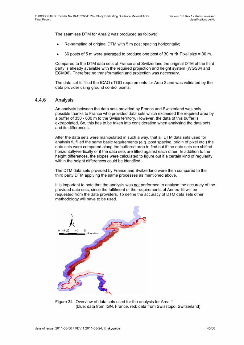
EUROCONTROL Tender No 10-110288-E Pilot Study Evaluating Guidance Material TOD version: 1.0 Rev.1 / status: released Final Report classification: public
The seamless DTM for Area 2 was produced as follows:
Re-sampling of original DTM with 5 m post spacing horizontally;
36 posts of 5 m were averaged to produce one post of 30 m Pixel size = 30 m.
Compared to the DTM data sets of France and Switzerland the original DTM of the third party is already available with the required projection and height system (WGS84 and EGM96). Therefore no transformation and projection was necessary.
The data set fulfilled the ICAO eTOD requirements for Area 2 and was validated by the data provider using ground control points.
4.4.6 Analysis
An analysis between the data sets provided by France and Switzerland was only possible thanks to France who provided data sets which exceeded the required area by a buffer of 350 - 600 m to the Swiss territory. However, the data of this buffer is extrapolated. So, this has to be taken into consideration when analysing the data sets and its differences.
After the data sets were manipulated in such a way, that all DTM data sets used for analysis fulfilled the same basic requirements (e.g. post spacing, origin of pixel etc.) the data sets were compared along the buffered area to find out if the data sets are shifted horizontally/vertically or if the data sets are tilted against each other. In addition to the height differences, the slopes were calculated to figure out if a certain kind of regularity within the height differences could be identified.
The DTM data sets provided by France and Switzerland were then compared to the third party DTM applying the same processes as mentioned above.
It is important to note that the analysis was not performed to analyse the accuracy of the provided data sets, since the fulfilment of the requirements of Annex 15 will be requested from the data providers. To define the accuracy of DTM data sets other methodology will have to be used.
Figure 34 Overview of data sets used for the analysis for Area 1 (blue: data from IGN, France, red: data from Swisstopo, Switzerland)
date of issue: 2011-06-30 / REV.1 2011-08-24, skyguide 45/68

EUROCONTROL Tender No 10-110288-E Pilot Study Evaluating Guidance Material TOD version: 1.0 Rev.1 / status: released Final Report classification: public
Basel Geneva
Figure 35 Overview of data sets used for the analysis for Area 2 (blue: data from IGN, France, red: data from Swisstopo, Switzerland)
All issues which arose from the analysis of DTM are listed in Chapter 5.
4.4.7 Results
Since some of the DTM data sets had to be manipulated to fulfil the basic requirements the results might be influenced by this manipulation. As already mentioned above, French DTM data overlapping Swiss territory is extrapolated and is not certified by the French Geodetic Institute. In addition, the size of the areas which were used for the analysis differ a lot. Nevertheless some general statements can be made:
For Area 1 and 2: No regular shift horizontally or vertically could be identified, nor were the data sets tilt against each other. So, it was not possible to identify issues based on different data providers.
As it would be expected for flat areas, the differences are smaller compared to steeper areas.
Flat area Steep area
Figure 36 Considerations on accuracy for flat and steep areas
date of issue: 2011-06-30 / REV.1 2011-08-24, skyguide 46/68

EUROCONTROL Tender No 10-110288-E Pilot Study Evaluating Guidance Material TOD version: 1.0 Rev.1 / status: released Final Report classification: public
The Swiss DTM data set were generally higher for large-scale steep areas, whereas the French DTM were generally higher for small-scale steep areas. This is the same for Area 1 or 2.
For Area 1 and 2 the differences between the data sets available were calculated. For some rough statistical considerations each pixel with its calculated difference was considered as one measured value. Based on this approach the following general statements can be made:
Area 1: Calculation: DTM France minus DTM Switzerland: For Area 1 most of the calculated height differences are within the required 30 m (ca. 95 %). The maximal calculated height differences range from -169 m to 124 m. The area with the maximum values is located along the boundary of the data set (see remark above about extrapolation). In reality, this area is situated along a riverbank.
Area 2: DTM France, Switzerland and third party product were compared by calculating the height differences for all the possible combinations: For Area 2 the resulting height differences are for most of the calculations not within the required 90 %. For most of the comparisons the height differences decrease regularly.
4.4.8 Data exchange format for terrain data
For the exchange of DTM data a standard will support a smooth data exchange between different data providers and data users. In the GIS world such standard formats are established, but sometimes lack the notion of providing space for metadata.
The document "Terrain Data Model Primer" defining the TIXM was considered. Due to the lack of appropriate tools, this format was not used during the Pilot Study. However, some consideration was given to the subject and the findings are documented in Chapter 5.3.13.2.
date of issue: 2011-06-30 / REV.1 2011-08-24, skyguide 47/68

EUROCONTROL Tender No 10-110288-E Pilot Study Evaluating Guidance Material TOD version: 1.0 Rev.1 / status: released Final Report classification: public
5 Part 2: Findings and Recommendations
5.1 Introduction
The first part of this report describes the tasks performed within the Pilot Study. All issues which came up during the execution of the four work packages are summarised in this second part of the report. The issues are grouped to institutional and technical issues. The issues were discussed in detail within the project team and possible solutions were elaborated and carefully analysed. So, wherever possible, recommendations are provided. Nevertheless there are several issues were questions remain. They will need to be addressed to EUROCONTROL for solving.
5.2 Institutional Issues
5.2.1 Coordinated flow of information in cross-border Area 2
According to Annex 15, Chapter 3.1, every State is responsible for the publication of aeronautical data for its territory (exceptions defined in Annex 15, Chapter 3.1.7).
From this it follows that every country is responsible for the storage and maintenance of the obstacle data within the national boundary (obstacle master dataset) even though obstacles might be part of a foreign aerodrome. On the other hand the country, where the aerodrome is located, is responsible for the publication of the AIP AD sections with all the charts of the aerodrome containing all obstacles of Area 2.
The following discussion is based on the two definitions:
Obstacle Country The country where the obstacle is located
AD Country The country where the aerodrome is located
Bilateral agreements as a necessary prerequisite:
The cross-border part of the OLS of an aerodrome has to be “legalised” in the Obstacle Country i.e. the foreign OLS has to have the same legal effect as if the AD were in the country. This should be part of a bilateral agreement between the countries.
There has to be an agreement between the CAAs of both countries covering at least:
Which obstacles have to be exchanged for evaluation (Area, OLS, which additional objects according to Annex 15 recommendations, etc.);
Agree on financial responsibility and coverage for the cross-border areas;
What information about an obstacle has to be exchanged;
Maximal time limit to complete the evaluation and return the conditions;
Technical agreement: Agree on the feature capture rules, reference system and data exchange format.
date of issue: 2011-06-30 / REV.1 2011-08-24, skyguide 48/68

EUROCONTROL Tender No 10-110288-E Pilot Study Evaluating Guidance Material TOD version: 1.0 Rev.1 / status: released Final Report classification: public
Recommendation for a coordinated flow of information:
Trigger CAA of ANSP of
Aerodromecountry
Obstaclecountry
Aerodromecountry
Obstaclecountry
Notificationon planned
project
Evaluation/Assessment
with conditions
Permissionwith conditions
Information
Notificationon beginning
of construction
PublicationAMDTs to Products
Notificationon finalisationof construction
Inspection/Enforcement
Notificationon survey
Notificationon
deconstruction
Survey
Construction finalised
In Construction
Plannedobject
De-construction
CAACoordination
Obstaclestatus
Information flow between two countries Version 0.6 / 9.11.2010
Publicationsurveyed coord.
Publicationplanned coord.
PublicationAMDTs to Products
Update obstacle data
PublicationAMDTs to Products
Activity Description
CAA Coordination The CAA of the Obstacle Country receives the notification of a planned object, checks it for completeness and transfers the agreed Information to the CAA of the aerodrome.
Evaluation / Assessment with conditions
Evaluation of obstacle according ICAO Annex 14, PANS-OPS and CNS aspects done by the organisations of the AD Country within the agreed time limit.
Permission with condition Based on the input of CAA of Aerodrome Country CAA of Obstacle Country authorises (possibly with conditions to mark or light the object) or declines construction of the obstacle.
date of issue: 2011-06-30 / REV.1 2011-08-24, skyguide 49/68

EUROCONTROL Tender No 10-110288-E Pilot Study Evaluating Guidance Material TOD version: 1.0 Rev.1 / status: released Final Report classification: public
Activity Description
Publication planned coordination
ANSP in Obstacle Country updates the obstacle data set and publishes the required products (NOTAM) based on the planned and authorised coordinates of the obstacle.
Publication AMDTs to Products
ANSP in Aerodrome Country updates and publishes the products (AIP Amendments, charts) containing the obstacle.
Inspections/Enforcement CAA of Obstacle Country has the responsibility to ensure the object is built according to the authorisation (location, height) and to enforce the imposed conditions (marking/lightning).
Publication surveyed coord. ANSP in Obstacle Country updates the obstacle data set based on the surveyed coordinates of the obstacle. If necessary publishes NOTAM with new coordinates.
Update obstacle data The obstacle is removed from the obstacle data set.
5.2.2 Bilateral agreements
Issues:
As explained in paragraph 4.2.2, if all the issues to be clarified within bilateral contracts in the “Letter of agreement” proposed in the draft TOD Manual were considered as relevant, some additional difficulties were identified in the frame of this evaluation:
In the draft TOD Manual it is stated: “In many cases, arrangements will already be in place between AIS/AIM of neighbouring States”. Experience shows, that arrangements might be in place between States, however formal agreements are not written. Consequently, the contractual arrangements planned for eTOD will need to address all the cross-border issues related to obstacles, not only those related to eTOD;
Another question which might be more demanding to solve than expected is at which level the bilateral agreement have to be signed. As it will address all the cross-border issues related to obstacles, the feeling is that this agreement will have to be signed at least at State level and not only at the ANSP level. To achieve a bilateral contract at a State level, higher-ranking existing agreements have to be considered, e.g. in Europe, the Functional Airspace Blocks (FAB’s) might already include certain delegation of tasks between States. Consequently, based on these elements, it seems that this planned bilateral contract between two States at least has to be reviewed and probably also signed at a quite “high level”;
During the discussions that occurred on this planned bilateral contract, it appeared that it was not clear how detailed the following parts will have to be described and regulated: initial acquisition, maintenance, resurvey of the obstacles;
The need for different contracts per AD was also discussed. It was concluded that the answer to this question will depend on the answers to the questions mentioned above.
It is highly probable that separate Letters of Agreement may be needed for the State Level and the Service Provision level.
The State level will cover more general and institutional matters, specifying also which State or Organisation is responsible for which tasks. A separate Agreement between
date of issue: 2011-06-30 / REV.1 2011-08-24, skyguide 50/68

EUROCONTROL Tender No 10-110288-E Pilot Study Evaluating Guidance Material TOD version: 1.0 Rev.1 / status: released Final Report classification: public
ANSP may include more detailed and technical information about the responsibilities for the data collection, validation and publication, the data exchange between the organisations, copyright and financial compensation.
5.2.3 Borderline
Issue:
To know the exact limitation of the State territory an agreed borderline between all involved parties will be necessary. Since the maintenance of the borderline and its respective dataset is part of the tasks of the national Geodetic Institutes/Mapping Agencies, the provision of the required borderline should be delegated to these entities or their international organisation (e.g. for Europe Eurogeograhpics).
For eTOD purposes there will be no need for a very detailed borderline. So, the point density of the borderline should be defined based on the intended usage of the data set.
Recommendation:
The project team recommends the following:
Harmonised borderlines to be provided by national Geodetic Institutes/Mapping Agencies or their international organisation;
The level of detail of the borderline used for the definition of the coverage of an area should be defined in relation to the horizontal resolution of the DTM. For example it is not reasonable to use a borderline with 5 m point density for Area 1 with a post spacing of ca. 90 m.
5.2.4 Harmonised Publication Process
Issue:
For the definition of Area 2 a common understanding of the TMA has to be established between all involved States. When a cross-border TMA is published in the AIP of the different States involved, a harmonised publication process is necessary, so the same TMA data is published in all AIPs at the same date. Today it happens, that changes of TMA boundaries crossing borders are not published with the same effective date in all affected AIPs.
5.2.5 Considerations on costs for the implementation of eTOD
In the TOD Manual costs per airport are provided without detailed description of the requirements fulfilled or tasks performed for that specific cost estimate. Discussions with different surveying companies showed, that the estimate of 60 K€ per airport (see TOD Manual, Chapter 5.1.1.2, p. 82), assuming that all requirements are fulfilled, is too low.
With the experience of the survey campaigns commissioned by different authorities and executed by different companies according to different specifications, it became clear that the cost associated with the different data acquisition methodologies can not be compared. In addition not all tasks which need to be done for an implementation of eTOD were subcontracted to external parties. This makes it even more difficult to provide a transparent comparison of costs. Therefore the project team came to the conclusion to include some case studies with a description of the specifications used and the tasks included along with the associated cost. We strongly recommend not to include costs or cost figures into the TOD Manual. Guidance Material is intended to remain for a longer period of time and values which are included could be outdated within a short timeframe.
date of issue: 2011-06-30 / REV.1 2011-08-24, skyguide 51/68

EUROCONTROL Tender No 10-110288-E Pilot Study Evaluating Guidance Material TOD version: 1.0 Rev.1 / status: released Final Report classification: public
Equally important to knowing the survey cost from some case studies, is to know the cost influencing factors valid for any survey. Analysing the whole process of the surveys executed for this Pilot Study these factors can be divided in three groups:
Technical specifications;
Tasks included in the survey;
Configuration and topography of the aerodrome.
5.2.5.1 Technical specifications
One of the determining factors of the cost is the number of flight lines for data collection. When applying aerial photogrammetry the flying time and the number of stereopairs to be processed are directly dependent on the number of flight lines. The flying height and the number of flight lines are dependent on the specifications the surveyed data has to meet. The results of the test surveys show, not the accuracy requirement specified in Annex 15 is the determining factor, but the level of details to be captured. In other words: The smallest object which has to be in the data set determines the flight configuration. Independent of the capture method (photogrammetry or LIDAR), long and thin objects are the most difficult to be identified. From an economical point of view, one can never afford to collect all details (e.g. lightning rods on a roof, see Chapter 5.3.5). Therefore it is important that the product specification and metadata clearly describe what is included in an obstacle data set and what might be missing because it could not be detected. This allows the user of the data to take appropriate mitigation measures and to apply buffers accordingly.
Another major cost driving factor is the Level Of Details (LOD) required. It is a major difference whether a building is represented as a point with a height or a bounding box of the building or as a segmented object with parts (as currently recommended in the draft TOD Manual).
Before giving a cost estimate one has to agree what the requirements regarding the minimal detectable objects and LOD are.
5.2.5.2 Configuration and topography of the aerodrome
The terrain characteristics will heavily influence the costs for the obstacle derivation. The following factors were identified:
Topography: Assuming a perfectly flat terrain in the vicinity of the airport, the sloped obstacle collection surface will quickly (several 100 m from the runway threshold) reach a height above terrain where only a few major objects penetrate it and thus, have to be collected as obstacles. If, on the other hand, the terrain in this region rises as well and lies above the obstacle collection surface, every object with a minimal height above ground of 3 m (Area 2b) respectively 15 m (Area 2c) has to be collected as an obstacle. When applying LIDAR technology, effort for obstacle derivation per area can vary by as much as a factor of 30 between these extreme scenarios. One advantage of the LIDAR method is the highly automated way in which the point cloud can be analysed and truly relevant objects that both penetrate the obstacle collection surface and have the required minimum height above ground can be quickly identified. Large areas without obstacles don’t require any further analysis.
date of issue: 2011-06-30 / REV.1 2011-08-24, skyguide 52/68

EUROCONTROL Tender No 10-110288-E Pilot Study Evaluating Guidance Material TOD version: 1.0 Rev.1 / status: released Final Report classification: public
Figure 37 The difference in obstacle density between areas below (left side) and above (right side) of the obstacle collection surface in Area 2b
Ratio of built-up area: In built-up areas, the number of obstacles to be collected (buildings, poles, antennas, trees etc.) is many times higher than in open, rural areas. In this case, the availability of cadastre data for building footprints is very important and the effort for all processing steps is significant.
Figure 38 The difference in obstacle density between built-up (left side) and rural (right side) areas in Area 2b
Area 2b vs. Area 2c: The experience from the Pilot Study shows that the effort for obstacle derivation per area unit is approximately 10 times higher in Area 2b than in Area 2c since much more obstacles need to be collected with a minimum height above ground of 3 m than of 15 m.
date of issue: 2011-06-30 / REV.1 2011-08-24, skyguide 53/68

EUROCONTROL Tender No 10-110288-E Pilot Study Evaluating Guidance Material TOD version: 1.0 Rev.1 / status: released Final Report classification: public
Figure 39 Difference in obstacle density between Area 2b (lower left-hand side) and Area 2c (upper right-hand side)
5.2.5.3 Sharing cost
To minimise costs it is strongly recommended to first analyse what kind of data is already available and who has to perform regular surveys. Wherever possible existing data should be used. When preparing a survey, potential users of the data should be consulted whether they are interested in a combined data capturing, so that costs for the survey could be shared by different data users.
5.2.5.4 Case studies
For each case study the tasks performed are described in more detail.
Non-disclosure clause The use of cost numbers is limited to the EUROCONTROL TOD (PROJECT TEAM). No numbers shall be communicated to other parties (e.g. ICAO).
5.2.5.4.1 Airport Basel-Mulhouse (LFSB)
Table is based on the previous description of the cost driving factors:
What Description
Areas
- Incl. specific limitations
- DTM and/or obstacles
Areas 2a, 2b and 2c especially narrowed to Annex 14 conical surface limits (65 % of Area 2c) to reduce the number of flight axis. Only obstacles were plotted, terrain data comes from IGN, Swisstopo and LIDAR acquisition over Area 3 with a resolution of 2 points per sq km.
date of issue: 2011-06-30 / REV.1 2011-08-24, skyguide 54/68

EUROCONTROL Tender No 10-110288-E Pilot Study Evaluating Guidance Material TOD version: 1.0 Rev.1 / status: released Final Report classification: public
What Description
Topography of aerodrome
Steep terrain: one of the hilliest aerodromes among French metropolitan aerodromes (ca. 40 % of west part of Area 2c are above collection surface, and ca. 20 % of the south part of Area 2b are above collection surface).
Building density Medium (ca. 30 %)
Runway configuration A single runway taken into account
Preconditions Availability of geodetic points and 1 arcsecond DTM from national Geodetic Institute
Data capture specifications
No segmentation (except spires of churches and 10 points per 1 ha in forests).
About forty different obstacle types are described. Level of detail close to LOD1 (Level Of Detail 1 with “blocks model comprising prismatic buildings with flat roof” as introduced in the TOD Manual Appendix B “Feature Capture Rule” in paragraph B.1.2).The main geometric rules for obstacle capture in Area 2 are:
line obstacle if its length is greater than 8 metres and its width is less than 5 metres;
polygon obstacle if its surface is greater than 40 square metres;
point obstacle in other cases;
contiguous obstacles share common edges;
required vertices if XYZ intersection.
There are additional rules:
elevation of a roof should be registered through the highest elevated point;
the height of an obstacle should be calculated through a ground point;
based on Type A Chart requirements by experience, shape of vegetation areas are determined by about one captured tree per 10 ha within a vegetation area.
Surveying technique
Photogrammetry combined with vertical LIDAR: with ca. 50 cm ground pixel resolution aerial photography over Areas 2b and 2c (limited to the conical surface), and ca. 20 cm ground pixel resolution aerial photography with ca. 2 points per square metre over Areas 2a and 3. Flight heights: ca. 2 100 m (for GSD=0.20 m) over Areas 2a, 3, 4 and ca. 5 100 m (for GSD=0.50 m) over Areas 2b, 2c (narrowed to conical surface limits).
Resulting data: raw obstacles with national grid projected coordinates (without attributes), and classified points coming from LIDAR acquisition.
Tasks included in the given cost range
List of tasks included in the contracted survey (and in the cost range).
Aerial photography (combined with LIDAR acquisition on Area 3): 2 hours flight.
Field survey of aerotriangulation control points and reconnaissance mission before stereo plotting.
Obstacle plotting.
Structuring in WGS84 3D shapefiles.
Independent quick fieldwork checking (including about 20 survey stations with 300 m radius in order to verify the elevation of highest point measured for each observable obstacle and to report points
date of issue: 2011-06-30 / REV.1 2011-08-24, skyguide 55/68

EUROCONTROL Tender No 10-110288-E Pilot Study Evaluating Guidance Material TOD version: 1.0 Rev.1 / status: released Final Report classification: public
What Description which would be higher than those stereo plotted).
Tasks excluded from the cost
Tasks that were necessary, but not part of the cost, e.g. tasks performed by ANSP or other parties.
SIA data checking through cross checking with existing data (topographic reference database, terrestrial surveys, etc.).
Values for attributes “Lighting” and “Marking” to be provided by local authorities.
DTM computing (clipping, projecting, etc.).
DTM license.
5.2.5.4.2 Airport Geneva (LSGG)
What Description
Areas Area 2a, 2b and 2c Obstacles
Topography of Aerodrome
Hilly in the north-eastern part
Lake in the outer western part of Area 2b
Building density City in the south-western part
Runway configuration Single runway
Preconditions Within Switzerland building footprints in good quality available from cadastral survey were used
Data capture specifications
Obstacle type catalogue: tower, silo (point and polygon), mast, crane, church, electricity pylon, building (point and polygon), tree, antenna, airfield lightning, street, telephone line, forest, high-power line, fence
LOD1, no obstacle segmentation
No lighting / marking information captured
No Height AGL captured
Threshold Value T for geometric representation according to TOD Manual B.2.1.3
Surveying Technique
Photogrammetry
GSD (ground sampling distance): 15 cm
Tasks included in the given cost range
Preparation (incl. ground points, flight preparation)
Flight
Photogrammetric triangulation
Orthophoto creation for control purposes
Photogrammetric plotting
Database creation
Field checks including proof of quality
Quality report
Tasks excluded from the cost
Translation of the data to AIXM
date of issue: 2011-06-30 / REV.1 2011-08-24, skyguide 56/68

EUROCONTROL Tender No 10-110288-E Pilot Study Evaluating Guidance Material TOD version: 1.0 Rev.1 / status: released Final Report classification: public
5.2.5.4.3 Fictitious example with LIDAR
Based on the Zurich Pilot Study the data capture cost for the LIDAR technology was estimated:
What Description
Areas Area 2a, 2b and 2c Obstacles and DTM
Topography of Aerodrome
Flat Hilly
Building density Sparsely built-up, rural Densely built up, urban
Runway configuration Single runway
Preconditions Building footprints in good quality available from cadastral survey and used
Data capture specifications
Obstacle type catalogue : Building, vegetation (trees and forest areas), pole, power line, fence, crane
LOD1, no obstacle segmentation
No lighting / marking information captured
Height AGL captured
Threshold Value T for geometric representation according to TOD Manual B.2.1.3
Surveying technique
LIDAR: Forward tilted Sensor; approximately 8 pts/m2; vertical point distance: 2.5 m
Tasks included in the given cost range
Preparation (incl. ground points, flight preparation)
Flight with raw data collection
LIDAR data processing:
- Triangulation
- Filtering and DTM / DSM creation
- Point classification
Vectorisation and database creation
Field checks including proof of quality
Quality report
Tasks excluded from the cost
Translation of the data to AIXM
5.2.5.5 Conclusions and further considerations
In the previous chapters a number of factors influencing costs for the implementation of eTOD were presented. It can be concluded that the presented factors influence cost regardless of the technology used. However, some additional aspects need to be considered with respect to the technologies applied:
Manual versus automated tasks in the applied processes data collection and processing labour costs versus cost of automation (equipment, software, algorithms, etc.);
Evolution of the applied methodologies and technologies for data collection and processing cost efficiency, quality and completeness;
determine the suitability of available data for the use in combination with a specific technologies change detection, completeness, costs;
date of issue: 2011-06-30 / REV.1 2011-08-24, skyguide 57/68

EUROCONTROL Tender No 10-110288-E Pilot Study Evaluating Guidance Material TOD version: 1.0 Rev.1 / status: released Final Report classification: public
overall cost considerations not only taking into account initial costs but as well overall costs for the data life cycle in the context of the technologies to be applied costs, quality, maintainability.
Based on above considerations, we recommend that not only cost of the involved technologies are taken into account but enhance the scope to include initial data acquisition cost as well as the whole lifecycle of the data set.
5.3 Technical Issues
5.3.1 Comparison of Annex 4/14/15
Issue: Extent of Areas 2a and 2b
First of all, ANSPs and surveyors need to know if Area 2a should exactly include runway strip and clearways. In that case, 1.2 % slope of Areas 2b and 2c is not efficient to comply with Obstacle Limitation Surfaces (e.g. inner horizontal surface has a height of 45 m and a 4 km radius). Annex 15 restricts Area 2b to 10 km from the end of Area 2a. This limitation to 10 km seems not to be compliant with Annex 14 and should therefore be extended to 15 km.
It is essential to have a comparison of the obstacle surfaces defined in the different ICAO Annex including graphics for vertical and horizontal comparison. This comparison should include as well a definition of an all-encompassing area which allows the collection of all relevant objects at once. A filtering of objects based on the rules of the different Annex could be done afterwards.
5.3.2 Interpretation of definition of Area 2b
Issue: Direction of Area 2b
Annex 15 states the following in the text of Figure A8-2: …
'b) Area 2b: an area extending from the ends of Area 2a in the direction of departure…..'
The statement is not clear and could be interpreted in two ways:
extension of the centreline of runway as a straight line
take-off path as defined in Annex 14 impact on area definition
objects in the take-off flight path area for AOC should have 3 m minimum height
It is mentioned, that for Area 2b the data has only to be captured in the direction of departure. This leads to the conclusion that no Area 2b for runways with only arrival will be provided.
5.3.3 Segmentation of buildings
Issue:
Within the areas of the Pilot Study no areas could be identified for which it would be of operational benefit to perform vertical segmentation on buildings. So, no segmentation for buildings was done.
date of issue: 2011-06-30 / REV.1 2011-08-24, skyguide 58/68

EUROCONTROL Tender No 10-110288-E Pilot Study Evaluating Guidance Material TOD version: 1.0 Rev.1 / status: released Final Report classification: public
Proposal for the TOD Manual:
This issue was discussed during the meeting held on 21.07.2010. During this discussion the following proposal was developed with EUROCONTROL:
The TOD Manual will recommend to segment buildings only at places where it is of operational benefit. Note: The main text of the TOD Manual V1.0, 7.6.2010, p.165 states 'It is recommended that the following vertical segmentation rules are applied to obstacles: ....' The advice not to segment buildings is only included in the footnote. From our point of view it will be important to recommend in the Guidance Material that, as a standard, no segmentation should be used. Of course if a State decides to use segmentation, then the guidance in the TOD Manual shall be used;
If segmentation will have to be done, the TOD Manual will give guidance how to do it;
To reflect if segmentation was done or not, metadata will have to provide the information. Therefore it is planned to propose the implementation of two new attributes for metadata within AIXM: - vertical segmentation used: yes/no - where the footprint is: ground/OLS
5.3.4 Segmentation of vegetation
Issue:
The representation of dense trees or forest areas is an issue. After an extensive discussion with the surveying companies and the topographic agencies providing the DTM the project team came to the following recommendation.
Recommendation:
The project team recommends dealing with forested areas as follows:
Forest will not be included in the DTM. The DTM will represent the plain earth;
Boundaries of forest as 2D polygons with the maximum elevation of the forest;
Within the forest capture trees as single points in 3D. Proposal for density of single trees: 1 tree per 10 ha. Note and Rationale: The proposed single tree density is based on Clermont-Ferrand campaign in order to update the Aerodrome Obstacle Chart ICAO Type A (refer Annex 4 item 3.8.1). A single vegetation area with the elevation maximum is obviously too stringent. Tree points in the vegetation area necessary. Density of tree points will depend whether the terrain is flat. Local maxima could be used when data is captured by LIDAR.
5.3.5 Detectability of thin objects
Issue:
The users of electronic obstacle data have to be aware that independent of the data capture method (photogrammetry or LIDAR) there will be limitations to what objects can be detected. Specially some thin antennas and lightning rods are likely to be missed with sensor configurations used in the Pilot Study projects (see Figures below).
date of issue: 2011-06-30 / REV.1 2011-08-24, skyguide 59/68

EUROCONTROL Tender No 10-110288-E Pilot Study Evaluating Guidance Material TOD version: 1.0 Rev.1 / status: released Final Report classification: public
Figure 40 Illustration of a missing object
Highest point
Height detectedwith laser scanning
Figure 41 Illustration of a not correct detected object
5.3.6 Obstacle attribute "Height"
Issue: Calculation of obstacle attribute "Height"
According to Annex 15 the height of an obstacle (above ground) is an optional attribute in the data set. The experience of the Pilot Study showed that specially for polygonal obstacles the determination of the height of an obstacle is not without ambiguity. For a house standing on a slope it is not clear if the height is defined as the minimal, the maximal height or an average. A similar case is the height of a power line: is the height of the power line the highest pole or the highest distance of the cable from the ground (e.g. when traversing a valley).
When obstacles are captured by airborne methods like photogrammetry or LIDAR, the height can only be derived by calculating the difference between the top elevation of the obstacle and the elevation of the ground. With respect to error propagation this is accurate if the obstacle elevation and the terrain elevation is originating from the same
date of issue: 2011-06-30 / REV.1 2011-08-24, skyguide 60/68

EUROCONTROL Tender No 10-110288-E Pilot Study Evaluating Guidance Material TOD version: 1.0 Rev.1 / status: released Final Report classification: public
survey. If the heights of obstacles are derived from different sources (e.g. one survey for DTM and another survey for the obstacle elevations), uncertainties can occur.
Recommendation:
The project team recommends the following:
When applying airborne surveying methods, "Heights" are only filled in, if the same survey methods could be used for the determination of the ground and obstacle elevation, e.g. if a maximum DTM for the height determination is used, the heights will be too low and could end up to be hazardous;
For each obstacle it should be noted how the height was calculated based on ground points or DTM.
Issue: Definition of height for specific objects
In addition, it should be considered that for some obstacles it is not clear what the height will be. Examples: buildings at the hillside, cable cars, etc. User requirements will help to define how such object should be treated. Additional guidance by EUROCONTROL will be helpful for clarification.
5.3.7 Test cases for verification and validation
Issue:
Although surveyors obviously agree that their results are verified, they have some difficulty to understand the text and the philosophy of quality within their application to prove a "posteriori" that the results are compliant because they have always been supposed to work by the book (i.e. with the outmost professionalism).
France and Switzerland chose 2 different approaches to verify and validate the survey results:
France:
Comparisons with data from topographic database and from precedent surveys are carried out by SIA during the acquisition;
Independent survey will be done through 300 m radius survey stations to check accuracy and completeness.
Switzerland:
Show evidence of completeness is part of the order. The surveyor will have to prove it and will deliver a quality report.
The TOD Manual provides theoretical guidance only and should be more practical. Logical consistency and topology are quite easy to verify with GIS tools. On the other hand, completeness and accuracy are more costly to verify:
Comparisons with other sources of data (or additional fieldwork) are complicated by the level of detail and require selecting data to be checked (e.g. corners of buildings are often different in databases depending on the scale and expected usage whether cartographic or not; and the highest tree or roof mounted antenna are often uncertain or inaccessible);
date of issue: 2011-06-30 / REV.1 2011-08-24, skyguide 61/68

EUROCONTROL Tender No 10-110288-E Pilot Study Evaluating Guidance Material TOD version: 1.0 Rev.1 / status: released Final Report classification: public
Cross checking with reference data implies to cope with propagation of measurement uncertainty (i.e. how to qualify a dataset according to the standard deviation of reference data);
Thin obstacles are not always detectable through one technique but can be detected by another one (e.g. terrestrial survey is a good way to check dubious data according to different sources);
Due to measurement uncertainties, relevant obstacles for procedure design should be especially checked and listed (end users such as procedure designers have to take into account confidence levels).
Recommendation:
The project team recommends the following:
The TOD Manual should give more explanations or references about relevant sampling (i.e. number and selection) and acceptable interpretation of results (depending on type of obstacle and accuracy of reference data);
The TOD Manual should precise how the samples and interpretation of results can be provided;
Relevant obstacles for procedures design should be especially checked and listed (when a procedure has to be checked or updated, former relevant obstacles and constraints are known; when a new procedure is designed, potential significant obstacles and their surroundings have to be checked because of unreachable absolute completeness).
5.3.8 Data Product Specifications (DPS)
Issue: Harmonised DPS
The TOD Manual describes the content of a DPS. For the implementation it would be recommended to have harmonised DPS. Therefore one DPS for obstacle and one for terrain for each Area 1, 2, 3 and 4 should be added to the TOD Manual.
Issue: Support/Tool for maintenance of DPS / data catalogue and metadata
Parts of the information in the DPS, the data catalogue and the metadata are the same. Therefore an adequate tool could support the generation and maintenance of all these documents/information. E.g. skyguide uses word documents for the DPS and the related Data Transfer Specifications (DTS). The effort to keep all these documents up to date is high and there is a certain risk that an item is missed to be updated.
5.3.9 Coverage of area along the borderline
Issue:
According to ICAO, each State is responsible to provide the DTM data covering the States territory for Area 1. So, the provider of the DTM has to make sure that the whole territory of the State is covered and that no holes will appear when the DTM of two neighbouring States are merged.
date of issue: 2011-06-30 / REV.1 2011-08-24, skyguide 62/68

EUROCONTROL Tender No 10-110288-E Pilot Study Evaluating Guidance Material TOD version: 1.0 Rev.1 / status: released Final Report classification: public
Figure 42 Borderline (red line) and DTM illustrating the issue coverage of DTM data along the borderline
The borderline of a State will be a vector data set, whereas the DTM could be provided as raster data set (discrete data). Therefore it might happen that not 100 % of the State territory is covered by the DTM data set. If two neighbouring States provide DTM data sets which will be merged it might happen that holes appear along the borderline. To avoid this we recommend the following:
Proposal for discussion:
Define a tiling scheme for data provision (e.g. 1 minute by 1 minute). Based on the tiling scheme the data provider of neighbouring States (e.g. national Geodetic Institutes/Mapping Agencies) will have to be requested to agree on the tiles to be provided along the border. Like this it is ensured that the area along the border is covered without any holes.
Alternatively, the use of seamless data set provided by a third party (commercial) supplier could be discussed. Some more considerations regarding this subject are presented in Chapter 5.3.12.
5.3.10 Merging of DTM data sets
Issue:
Taking the position of a user (e.g. PANS-OPS, CNS, airline operator....): such a user is interested to get a seamless dataset for his area of interest independent of borders. So, for Area 2 crossing borderlines it might be necessary to merge DTM data sets from different data providers.
Like many others the above mentioned users will not be in a position to match the different patches of DTM data they will get from all the required data sources. This is even more important from an operational point of view as it might have safety impacts. An ANSP/AIM provides data from authoritative sources as mandated by the State (ANSP mandated by the State for international regulated data). So, he won't merge (change!) authorised datasets neither.
date of issue: 2011-06-30 / REV.1 2011-08-24, skyguide 63/68
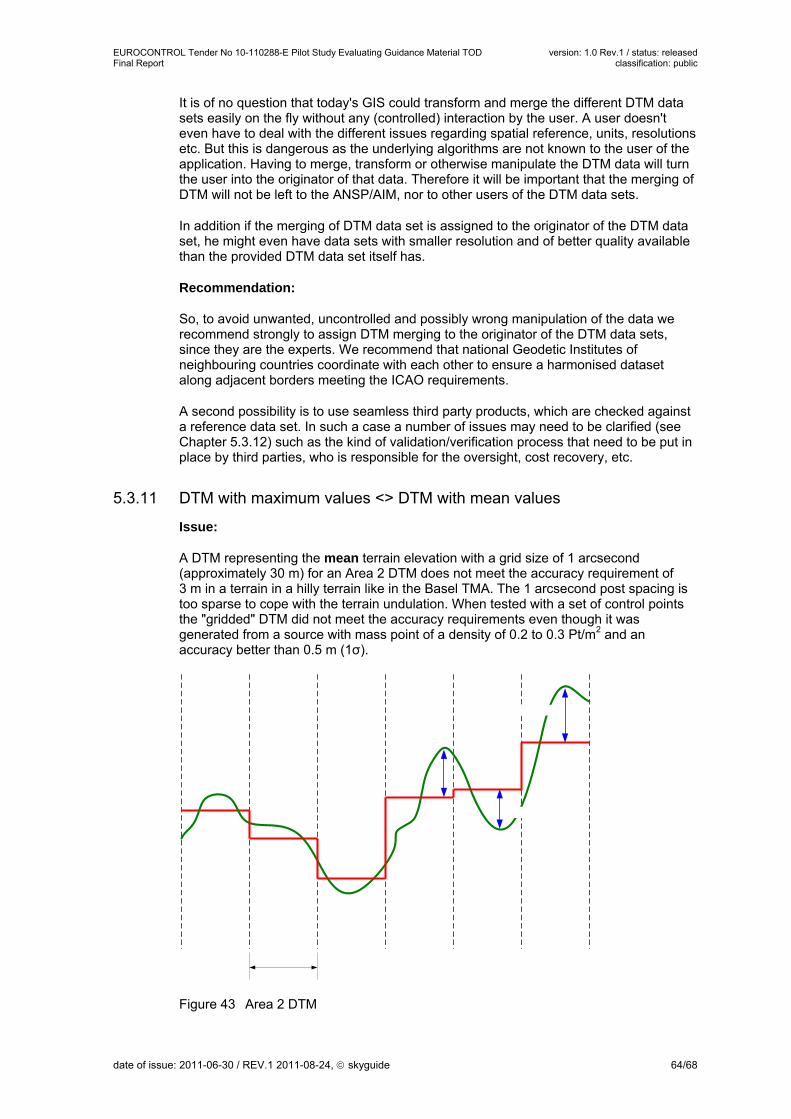
EUROCONTROL Tender No 10-110288-E Pilot Study Evaluating Guidance Material TOD version: 1.0 Rev.1 / status: released Final Report classification: public
It is of no question that today's GIS could transform and merge the different DTM data sets easily on the fly without any (controlled) interaction by the user. A user doesn't even have to deal with the different issues regarding spatial reference, units, resolutions etc. But this is dangerous as the underlying algorithms are not known to the user of the application. Having to merge, transform or otherwise manipulate the DTM data will turn the user into the originator of that data. Therefore it will be important that the merging of DTM will not be left to the ANSP/AIM, nor to other users of the DTM data sets.
In addition if the merging of DTM data set is assigned to the originator of the DTM data set, he might even have data sets with smaller resolution and of better quality available than the provided DTM data set itself has.
Recommendation:
So, to avoid unwanted, uncontrolled and possibly wrong manipulation of the data we recommend strongly to assign DTM merging to the originator of the DTM data sets, since they are the experts. We recommend that national Geodetic Institutes of neighbouring countries coordinate with each other to ensure a harmonised dataset along adjacent borders meeting the ICAO requirements.
A second possibility is to use seamless third party products, which are checked against a reference data set. In such a case a number of issues may need to be clarified (see Chapter 5.3.12) such as the kind of validation/verification process that need to be put in place by third parties, who is responsible for the oversight, cost recovery, etc.
5.3.11 DTM with maximum values <> DTM with mean values
Issue:
A DTM representing the mean terrain elevation with a grid size of 1 arcsecond (approximately 30 m) for an Area 2 DTM does not meet the accuracy requirement of 3 m in a terrain in a hilly terrain like in the Basel TMA. The 1 arcsecond post spacing is too sparse to cope with the terrain undulation. When tested with a set of control points the "gridded" DTM did not meet the accuracy requirements even though it was generated from a source with mass point of a density of 0.2 to 0.3 Pt/m2 and an accuracy better than 0.5 m (1σ).
Figure 43 Area 2 DTM
date of issue: 2011-06-30 / REV.1 2011-08-24, skyguide 64/68

EUROCONTROL Tender No 10-110288-E Pilot Study Evaluating Guidance Material TOD version: 1.0 Rev.1 / status: released Final Report classification: public
Recommendation:
For hilly terrain only a DTM representing maximum values can guarantee that with a probability of 90 percent the true terrain is not more than 3 m higher than the interpolated DTM. As a consequence the maximum DTM will be systematically higher than the true terrain. The error distribution between true terrain and DTM will not be a normal distribution. Therefore an accuracy specification of a maximum DTM of 3 m (confidence level 90 %) does not make much sense except when defined what it means, like e.g. the probability that the true terrain exceeds the DTM by more than 3 m is less than 10 %.
5.3.12 Considerations on DTM data sets
Issue:
For airports where the Area 2 is across national boundaries it might be of interest to use a seamless dataset provided by an industrial provider as no merging of different national data sets will be necessary and the quality of the data will be the same across the whole territory covered. Even though such a seamless data set will remove some of the difficulties mentioned earlier, some issues should be considered:
Licensing As this data needs to be made available as defined by ICAO, care should be taken on the possible limitations a third party licensing scheme imposes on the use of the data.
Validation and validation methods To demonstrate that the product fulfils the requirements according to Annex 15 it will be necessary that the product passes some kind of validation. The question that arises from that is which methodology should be used.
Maintenance The update cycle for the seamless data set needs to be negotiated and should be in line with the requirements of the aeronautical requirements.
Recommendation:
Additional guidelines how such a process can be performed, methodologies etc. should be given. Important is to define a comparable methodology and consequential the validation provides evidence that a product could be used for the purpose foreseen.
The negotiation of a contract with a third party supplier should take into account the obligation a State has to make the data available, the maintenance, etc. A good idea would be to form a group with several States that negotiates the contract.
5.3.13 Data exchange formats
5.3.13.1 AIXM
The data model AIXM has been developed to be used as the exchange model for static and dynamic aeronautical data between ANSPs across the world, so interoperability between different systems can be ensured. Newer developments in SESAR towards a System Wide Information Management (SWIM) lead to the development of a wider model (including AIM, MET, ATFM, etc.), the ATM Information Reference Model (AIRM), whose aeronautical information part is based on AIXM.
date of issue: 2011-06-30 / REV.1 2011-08-24, skyguide 65/68

EUROCONTROL Tender No 10-110288-E Pilot Study Evaluating Guidance Material TOD version: 1.0 Rev.1 / status: released Final Report classification: public
AIXM 4.5 only covers point obstacles but no line and polygon obstacles and does not support all eTOD attributes. The data model AIXM in its current version 5.1 covers all three geometric types for the obstacles: point, line and polygon.
In the Pilot Study for the data delivery from the surveyor to the ANSP the GIS format ESRI shapefiles was used in France and Switzerland.
Issue:
Today, in almost all States, national guidelines for surveyors exist. Usually, these guidelines also cover the data exchange between surveyors and the administration. In Switzerland, for example, this format is known as INTERLIS. In other countries CAD data formats (e.g. DXF) or GIS data formats (e.g. ESRI shapefile) are used as standard for data exchange.
The issue now is the exchange model which will be used between surveyors and ANSPs, France and Switzerland do not intend to force the surveyors to switch to AIXM to deliver data to the ANSP. We rather recommend the ANSP be able to accept the national exchange format and import it into the database as part of the upstream tasks. In the downstream part, where data is delivered to the next intended user, or shared with other ANSP's, the ANSP must be able to transform the data into a standardised exchange format as requested by the ADQ IR. This approach will certainly ease the cost for the introduction of eTOD as no software tools need to be developed and no AIXM training of the surveyors will be necessary. However, a model needs to be elaborated ensuring that all elements required are present and the ADQ IR requirements are met.
Note: SW tools which allow a transformation either from AIXM 4.5 or ESRI shapefile to AIXM 5.1 are not available. GIS tools as for example ESRI ArcGIS suite based on FME from SAFE Corp. have not yet provided AIXM 5 tools (information verified in July and in December 2010). Although AIXM 5 java toolkit exists, ANSPs are not recommended to develop themselves tools which could not be certified, but should leave this to the industry.
5.3.13.2 TIXM
Issue:
As mentioned earlier, a standard exchange format for terrain data is desirable. The widely used formats in the GIS world sometimes lack the metadata capability. Therefore the concept of TIXM, as an exchange format, providing an envelope for data files including metadata associated with the data, is appreciated. Even though its state is draft and the development is still ongoing we believe that the envelope capability is the most useful part in the specification.
Note:
For the evaluation of TIXM the document "Terrain Data Model Primer" and the TOD Manual were used. In the first document it is mentioned that detailed information on the application of TIXM will be provided by the TOD Manual. In the TOD Manual this information is missing.
date of issue: 2011-06-30 / REV.1 2011-08-24, skyguide 66/68

EUROCONTROL Tender No 10-110288-E Pilot Study Evaluating Guidance Material TOD version: 1.0 Rev.1 / status: released Final Report classification: public
6 Annex
6.1 Project Schedule E
UR
OC
ON
TR
OL
TR
S 1
0-1
1028
8:
Ter
rain
an
d O
bs
tacl
e d
ata
surv
eys
Wor
kpla
n
3W
44
W45
W4
6W
47W
48
W49
W50
W5
1W
52
Del
iver
able
s
Mil e
ston
eW
19W
20
W21
W2
2W
23W
24
W25
W2
6W
27W
28
W2
9W
30W
31
W32
W3
3W
34W
35
W36
W3
7W
38W
39
W4
0W
41W
42
W4
Sta
rt D
ate
10.
05.2
010
to
EU
RO
CO
NT
RO
LD
eliv
erab
le 1
- W
ork p
lan
15.
06.2
010
Sta
tus
Rep
ort 1
31.
07.2
010
Sta
tus
Rep
ort 2
15.
09.2
010
Del
iver
able
2 -
Sur
vey
Exe
cutio
n1
0.10
.20
10
Del
iver
able
3 -
Rep
ort
10.
12.2
010
rk
21.0
7.20
1020
10S
epte
mbe
rO
ctob
erN
ovem
ber
Dec
embe
rM
ayJu
neJu
lyA
ugus
t
WP
0: W
op
lan
Pro
ject
man
age
men
tW
orkp
lan
15.
06.2
010
bst
acle
man
aW
P1:
Og
emen
t p
roce
sses
H
ighl
evel
unde
rsta
ndin
gof
obst
acle
man
agem
ent
proc
esse
sF
and
CH
18.
06.2
010
Ana
lysi
ngth
eda
taex
chan
gew
ithin
this
proc
ess
betw
een
AN
SP
for
obst
acle
s w
ith r
egar
d to
eT
OD
re
quire
men
ts
01.
09.2
010
Pro
vide
firs
t res
ults
for
TO
D I
FG
21.
/22.
10.1
0 E
C(W
42)
20.
10.2
010
==
> r
epor
t:-
iden
tifie
d pr
oble
ms
- re
com
men
datio
ns f
or th
e gu
idel
ines
10.
12.2
010
late
ral c
on
trac
ts b
etw
een
AN
SP
A
ll or
gani
satio
nal i
ssue
s co
ncer
ning
eT
OD
, es
peci
ally
:-
obst
acle
Dat
a-
DT
M-
cost
allo
catio
n (r
emun
erat
ion)
To
cons
ider
the
del
e
WP
2: B
i
gate
d ai
rspa
ce f
or B
SL
and
GV
AP
rovi
de f
irst r
esul
ts f
or T
OD
IF
G 2
1./2
2.10
.10
EC
(W42
)2
0.10
.20
10
==
> r
epor
t:-
reco
mm
enda
tions
for
issu
es t
o be
gov
eren
ed b
y a
cont
ract
10.
12.2
010
bst
acle
su
rve
WP
3: O
yA
naly
sing
guid
elin
esfr
omE
UR
OC
ON
TR
OL
and
com
parin
gag
ains
t na
tiona
l gui
delin
esIn
tern
al R
evie
w is
sues
and
pre
para
tion
of c
omm
ents
P
oten
tial r
evie
w o
f is
sues
and
com
men
ts w
ith E
UR
OC
ON
TR
OL
Tes
tinE
Cg
the
data
exc
hang
e be
twee
n A
NS
P
3a:
Air
WP
po
rt B
SL
Suv
ey c
ontr
actin
gS
urve
y pr
epar
atio
nS
urve
y ex
ecut
ion
incl
udin
g da
ta c
aptu
ring
Ph
oto-
Flig
ht
Ana
lysi
ng th
e su
rve
y re
sults
3
0.09
.20
09
Pot
entia
l exc
hang
e of
exp
erie
nce
with
EU
RO
CO
NT
RO
L E
C(r
evie
w s
urve
y re
sults
)
TB
D
==
> D
eliv
ery
Dat
a sa
mpl
e of
1km
2 F
orm
ats:
- T
erra
in: T
BD
- O
bsta
cles
: TB
D
==
> r
epor
t:-
reco
mm
enda
tions
abou
tap
plic
abili
tyof
the
EU
RO
CO
NT
RO
Lgu
idel
ines
- te
chni
cal r
epor
t of
surv
eyin
g re
sults
- co
st e
stim
ate
10.
12.2
010
date of issue: 2011-06-30 / REV.1 2011-08-24, skyguide 67/68

EUROCONTROL Tender No 10-110288-E Pilot Study Evaluating Guidance Material TOD version: 1.0 Rev.1 / status: released Final Report classification: public
date of issue: 2011-06-30 / REV.1 2011-08-24, skyguide 68/68
EU
RO
CO
NT
RO
L T
RS
10-
1102
88:
Te
rra
in a
nd
Ob
stac
le d
ata
su
rvey
sW
orkp
lan
Mile
ston
eW
19W
20W
21W
22W
23W
24
W2
5W
26
W2
7W
28W
29W
30W
31W
32W
33
W3
4W
35
W3
6W
37W
38W
39W
40W
41W
42W
43
W4
4W
45
W4
6W
47W
48W
49W
50W
51W
52
WP
3b:
Air
no
t ye
t co
nfi
rme
d
po
rt G
VA
Suv
ey c
ont
ract
ing
Sur
vey
exec
utio
n in
clud
ing
data
cap
turin
gP
hot
o-F
ligh
t
Ana
lysi
ng th
e su
rvey
res
ults
E
CP
oten
tial e
xcha
nge
of e
xper
ienc
e w
ith E
UR
OC
ON
TR
OL
(rev
iew
sur
vey
resu
lts)
TB
D
==
> D
eliv
ery
Dat
a sa
mpl
e of
1km
2 F
orm
ats:
- T
erra
in: T
BD
- O
bst
acl
es: T
BD
==
> r
epor
t:-
reco
mm
enda
tions
abou
tap
plic
abili
tyof
the
EU
RO
CO
NT
RO
Lgu
idel
ines
- te
chni
cal r
epor
t of
surv
eyin
g re
sults
- co
st e
stim
ate
10.1
2.20
10
WP
4: D
TM F
:T
rans
form
atio
nof
natio
nal
DT
Min
WG
S84
/EG
M96
base
don
agre
ed p
aram
eter
s C
H:
Tra
nsfo
rmat
ion
ofna
tiona
lD
TM
inW
GS
84/E
GM
96ba
sed
ona g
reed
par
amet
ers
31.
08.
2010
Exc
hang
ebe
twee
nA
NS
Pan
dan
alys
eA
rea1
data
(buf
fer
alon
gbo
rder
) ba
sed
on a
n ag
reed
for
mat
Are
a 2:
Del
iver
y of
nat
iona
l par
ts o
f A
rea
2 D
TM
- F
ranc
e (B
SL
and
GV
A)
- S
witz
erla
nd (
BS
L an
d G
VA
)-
Ger
man
y (B
SL
only
)B
SL:
pro
duct
ion
of s
eam
less
Are
a2 d
atas
etG
VA
: pro
duct
ion
of s
eam
less
Are
a2 d
atas
etT
hird
part
y:co
mpa
rison
with
BS
L/G
VA
seam
less
Are
a2da
tase
tan
d A
rea1
dat
aset
(bu
ffer
alo
ng b
orde
r)T
est d
ata
exch
ange
TIX
M R
C1
for
suita
bilit
y=
=>
rep
ort:
- re
com
men
datio
ns f
or c
ross
bord
er is
sues
Are
a1-
reco
mm
enda
tions
for
cro
ssbo
rder
issu
es A
rea2
- re
com
men
datio
ns f
or T
IXM
RC
1
10.1
2.20
10
21.0
7.20
1020
10S
epte
mb
erO
ctob
erN
ovem
ber
Dec
em
ber
Ma
yJu
ne
July
Aug
ust