euraxles final report - cordis · of an axle, considering the fatigue limit scatter but also the...
TRANSCRIPT
EURAXLES – 265706 – Final Report
Page 1 of 63
EURAXLES FINAL REPORT
Grant Agreement number: 265706
Project acronym: EURAXLES Project title: Minimizing the risk of fatigue failu re of railway axles
Funding Scheme: Collaborative Project
Period covered: Whole project M1 – M42
Name of the scientific representative of the projec t's co-ordinator, Title and Organisation:
Léa Paties, Project Manager, UNIFE
Tel: + 32 2 643 70 81
E-mail: [email protected]
Project website address: http://www.EURAXLES.eu
EURAXLES – 265706 – Final Report
Page 2 of 63
Table of Contents
1. FINAL PUBLISHABLE SUMMARY REPORT ..................................................................... 3
1.1 EXECUTIVE SUMMARY ............................................................................................................................ 3 1.2 PROJECT CONTEXT AND OBJECTIVES .......................................................................................................... 3 1.3 MAIN S&T RESULTS AND FOREGROUND .................................................................................................... 7 1.3.1 WP2 - NEW AXLE FATIGUE DESIGN METHOD .......................................................................................... 7 1.3.2 WP3 - NEW TESTING METHODS OF RAILWAY AXLE FATIGUE LIMIT ASSESSMENT .......................................... 14 1.3.3 WP4 - TOOLS, TECHNOLOGIES AND SURFACE PROTECTION SYSTEMS MINIMIZING THE NEGATIVE INFLUENCE OF
CORROSION .................................................................................................................................................. 26 1.3.4 WP5 - NON- DESTRUCTIVE TESTING (NDT) AND VERIFICATION OF THE RELIABILITY OF AXLES IN SERVICE ......... 33 1.3.5 WP6 - RAMS AND LCC TAKING INTO ACCOUNT MARKET UPTAKE ........................................................... 39 1.4 POTENTIAL IMPACTS ............................................................................................................................ 45 1.5 ADDRESS OF THE PROJECT PUBLIC WEBSITE AND CONTACT DETAILS .............................................................. 46
2. USE AND DISSEMINATION OF FOREGROUND .............................................................. 47
3. SOCIETAL IMPLICATIONS ............................................................................................... 56
4. LISTS OF FIGURES AND TABLES ..................................................................................... 62
EURAXLES – 265706 – Final Report
Page 3 of 63
1. Final publishable summary report
1.1 Executive summary EURAXLES aims to bring the risk of failure of railway axles to such a minimum level that it will no longer be considered as a significant threat to the safe operation of the European interoperable railway system; at the same time, it shall keep the cost of maintenance to a reasonable level and minimise the risk of service disruption.
The global concept approach for axle design, production and maintenance includes:
• A design approach development, including a risk analysis method which could offer a simple design route by combining loads with difference occurrences including loading specificity of vehicles and service conditions together with the axles resistances, including new materials and methods in order to predict the ‘failure probability’.
• New developments will also include: o improved axle protection against corrosion, including protection of already corroded axles
o improved adhesion of coatings with a study of the roughness influence (adhesion and fatigue behaviour)
o new, innovative coating solutions. The new solutions will also aim to fulfil environmental requirements to avoid or limit VOC emissions.
• New/improved NDT inspection methods will allow the in-service inspection of axles in order to guarantee safe service conditions with a low impact on the vehicle availability.
• A RAMS/LCC analysis of the solutions will be carried out. The railway transportation system requires a risk analysis of the safety components. Activities will improve design validation and inspection technologies of axles which will optimise costs, safety and environmental compliance to be shown with RAMS/LCC analyses.
The EURAXLES global concept will not only guarantee the current level of safety, but improve it in an interoperable network at optimized cost.
1.2 Project context and objectives
WP2: New axle fatigue design method The main objectives of WP2 were:
o To develop a method to characterize the severity of real axle in-service loads, taking into account the variability of the load amplitudes and the variability of axles’ usages.
EURAXLES – 265706 – Final Report
Page 4 of 63
First of all, a database of on-line axle load measurements was set up, in order to gain a better knowledge of the variability of real in-service loads (Deliverable D2.1): data from the Dynotrain and Hembot projects were made available for the project duration and a test campaign was led by SNCF in order to gather additional data on a passenger coach running in France. From this load data, two simplified representative load spectra were extracted and distributed to all WP2 partners for further analyses.
In parallel, a method for the analysis of the axle fatigue loads was developed. Parametric analyses were performed and they showed, amongst others, the significant sensitivity of the results to the chosen damage law. This damage law was therefore accurately modelled and characterized, thanks to experimental results from WP3 on small specimen under variable amplitude loads. Then, a method to estimate the real distribution of the load severities was proposed by SNCF, based on the definition of elementary situations of life and the generation of virtual uses of axles. Finally, the method was applied to the SNCF passenger coach and the severity of the standardized load (defined in EN13103/13104) was estimated according to the distribution of load severity (deliverable D2.2).
o To introduce the use of the Finite Element Method in the modelling of axles in order to close some open points of the standards EN13103/13104, to give some recommendations for numerical modelling when using the FEM and to develop a commonly accepted numerical validation process of axles.
After defining the detailed geometries of the axles and the benches to be tested and simulated in WP2 and WP3, the numerical models were generated and the analyses were performed, for both trailer and motor axles. Similar results were obtained by all partners and the comparisons with the tests were satisfactory. The two types of bench (Minden and Vitry) also gave similar results. It was also observed that the concentration factors related to transitions defined in the EN13103/13104 are lower than those obtained by FEM calculations. Stresses in grooves derived from FEM were also found different from those obtained following the EN1310X rules. But in the meantime, experimental results from WP3 showed that the fatigue limits were underestimated in the standards, so that the current design process remains safe (as it can also be stated from return of experience from the field). A parametric analysis performed with transitions enabled the team to propose formulas giving the stress concentration factors depending on the axle geometrical parameters. Simulations of whole wheelsets were also performed. Finally, recommendations on how to use FEM in the validation process of axles and how to generate relevant FEM models were given (deliverables D2.3, D2.4).
o To develop a method to estimate the real in-service reliability (probability of failure) of axles, taking account of the variability of the loads and the scatter of the fatigue limits of steel grades A1N and A4T.
First, a semi-probabilistic approach, based on the Eurocode standard, was proposed by Polimi (deliverable D2.5) as an approach to validate an axle design. This method uses a “representative load spectrum” coming from measurements and enables one to propose minimum safety coefficients to be defined in the validation process, depending on the scatter of the material fatigue limits and simple assumptions made on the load uncertainties. A second method, fully-probabilistic, based on the Stress and Strength Interference Analysis, was also proposed by SNCF in order to estimate the probability of failure of an axle, considering the fatigue limit scatter but also the real distribution of the load severity, as defined in D2.2. The SNCF passenger coach trailer axle was taken as an application and its probability of failure was estimated, using the material characteristics identified in WP3 and the load measurements carried out in WP2. The calculated probability of failure is relatively small and its order of magnitude seems rather realistic (deliverable D2.6).

EURAXLES – 265706 – Final Report
Page 5 of 63
WP3: New testing methods of railway axle fatigue limit assessment The WP3 scope was to experimentally estimate fatigue limits of axles; such information is a main
input in the design. The WP considered axles made in standard material (A1N and A4T) and defined a standard method for testing and analyzing the obtained data from a statistical point of view in order to be able in the future to apply the same method in the characterization of new materials or new surface treatments.
Axle conditions considered for the actual testing were axles in standard surface finishing for which axle body (free surface) was evaluated separately from axles seats where wheel, brake disc or bearing press fits take place; in this later case the coupling of the components can generate, when high bending is applied to the axle, relative micro sliding and derived friction forces that end up in local wear and possible micro cracks of the seat side surface; the phenomenon is known as fretting corrosion and the result is that the fatigue limit is substantially lower than on the body. The severity of this phenomenon depends more on the geometry of the axle (Seat-body diameter ratio) than on the material itself; for this reason, different axle geometries were defined and tested. This part of the testing activity was complemented by task 3.3 dedicated to the theoretical modeling of fretting fatigue providing criteria for evaluating both the possibility for crack initiation and assessment of the crack propagation. The aim was to provide tools for optimizing the design.
An important subject that was treated in WP4 concerns the study of possible solutions that can improve the axles surface protection from corrosion and for this some surface treatment techniques were proposed (shot pinning, increase roughness ecc); as similar solutions can have an effect on the surface fatigue limit; some solutions were verified in WP3 trough simple 1/3 scale axles and then in full scale conditions.
WP3 also tested corroded axles to verify the actual reduction of the fatigue limit.
A common testing procedure was defined in order that similar tests performed in different laboratories could produce comparable results.
A list of small scale and full scale tests and the relative drawings were defined and the wheelset manufacturing partners prepared the materials for the tests. All tests were performed by 7 partners of the Project in their laboratories.
WP4: Tools, technologies and surface protection systems minimizing the negative influence of corrosion The main issue addressed by research activities in WP4 is that existing painting systems for wheel-set–axles, that meet the environmental requirements, often fail to meet all the requirements defined in the existing standard EN 13261 (Axles Product Requirements, e.g. chapter 3.9). Indeed, for environment protection reasons, legislation is moving from solvent-based paint systems to water-based paint systems.
The fatigue resistance of railway axles depends on the surface conditions. WP4 aims to advance beyond the state-of-the-art by resolving the problems associated with the existing surface coating methods used until now (corrosion, damage) through improved adhesion and new innovative coating and treatment processes, while considering the real service conditions and the environmental requirements.
The main objective of WP4 is to develop practical solutions for axle protection systems to avoid corrosion and damages with respect to the design/ calculation method, the product requirements, the inspection and maintenance requirements and the requirements of environmental legislation.
Given their experience, project partners analysed the current standards and determined their limitations in terms of testing and validation of protective coatings. Particular attention was given to the operating conditions of wheel-sets in service. Where necessary, alternative quality test methods are proposed with regard to operating conditions and reasonable costs.

EURAXLES – 265706 – Final Report
Page 6 of 63
The expected results of WP4 were new surface preparations and procedures for the design method of wheel-set axles, including new fatigue limits tested in WP3, associated to the new axle surface conditions (roughness or unpainted solutions). WP4 also aimed to investigate innovative and alternative protection systems, eliminating the need for paint application entirely, such as the improvement of hardness and corrosion resistance of wheel-set-axles by innovative treatment/ coating processes.
Regarding the possibility to have a design method without any painting system with defined corrosion level (SNCB is using paint-free axles for freight cars and passenger coaches) unpainted axles from service should be analysed in WP 4 in terms of surface aspect, corrosion, roughness and chemical composition. The objective was also to make fatigue test on about 10 axles from service without painting to determine a new fatigue limit.
The tasks of WP4 finally should include preparing recommendations to improve the existing standard for the product requirements of axles, recommending guidelines and also improved or new quality test methods.
WP5: Non destructive testing (NDT) and verification of the reliability of axles in service WP5 is focused basically in the study of the NDT methods applied by railway operators and maintenance companies in railway axles, to verify the detectability of these in order to guarantee safe service conditions with a low impact on the vehicle availability.
The main objectives of the Work Package are as follows:
Review of the current practice NDT techniques used in preventive maintenance in railway axles, to highlight the weakness and strengths of each method and to find possible points of improvement and solve potential risks which are not addressed by these methods.
The study of a new inspection method based on a new on-board continuous measurement technique. This technique describes a new methodology of diagnosis and classification of flaws in order to develop a new robust NDT method for axle inspection that could be classified as a condition based maintenance technique. This method is based in a sophisticated signal processing procedure that uses vibration signals obtained during rotation of the axle.
Verification of the influence of surface damage and corrosion in service using standard electrochemical and other NDT techniques. Different NDT techniques are reviewed for monitoring of corrosion and cracking in train axles without the need of disassembly.
The investigation of a novel crack detection method based on the change of the elastoresistive behaviour of an adhesive plug using electrochemical techniques, to detect cracks in railway axles.
WP6: RAMS and LCC taking into account market uptake In WP2 to WP5, the technical parameters for implementation of the design solutions (coated/non coated surfaces, type of protection, coating thickness, effect of corrosion, etc.) together with adequate inspection technologies to detect defects on axles in real service conditions have been investigated.
Technical aspects of the studied technologies must be complemented by cost analysis in order to assess the translation from research to the application in real operation. Hence, the main objective of WP6 is to review and analyze the market uptake of different solutions developed during the present project.
The overall safety and economic assessment will follow RAMS/LCC methodologies, a recognized method for assisting optimization processes in engineering systems. A common RAMS/LCC tool will be first defined between the participants and afterwards applied for the analysis of the different solutions in order to identify the preferred solutions for future applications and to understand the RAMS and LCC implications for an optimal market uptake. The analysis requires the data collected from the return of
EURAXLES – 265706 – Final Report
Page 7 of 63
experience provided by the partners and collaborators which is used as the reference to evaluate the innovative solutions developed in the project.
The common approach to RAMS/LCC analysis defined in EURAXLES can serve as a starting point for unified safety and cost evaluation of railway systems in general and wheelsets in particular within the European railway industry.
1.3 Main S&T results and foreground
1.3.1 WP2 - New axle fatigue design method
Objectives In WP2, the 4 main technical objectives were:
- To build a database of in-service loads measurements (Deliverable D2.1)
- To develop a new methodology to analyze in-service loads in order to characterize the distribution of fatigue load severities and compare it to the normative loads defined in EN13103/13104 (D2.2)
- To develop a new method to calculate accurately the stresses in the axles using the Finite Element Method, to give some recommendations on the FEM models development and to develop a commonly accepted numerical validation process of the axles (D2.3, D2.4)
- To define a general axle fatigue reliability approach which takes into account the variability of the in-service loads and the scattering of the axles strength in order to estimate the probability of fatigue failure in service (D2.5, D2.6).
Task 2.1: Characterization of the in-service loading severity
• Sub-task ST2.1.1 is dedicated to the generation of a database of real in-service axle loads (D2.1).
Load data were made available from the European project Dynotrain by their owners (DB, SNCF, TrenItalia, Alstom and Bombardier) and the European project Hembot (TrenItalia, Ansaldo Breda) only for the duration of the Euraxles project and for DB, SNCF and TrenItalia. Additional measurements were carried out by SNCF in February and April 2012 on a passenger coach axle, circulating in France (over 2000km of acquisition) at a maximum speed of V=160km/h, with an axle load of 14t. The sets of data were judged sufficient for the scopes of the in-service axles fatigue analyses (Task T2.1) since the ambition of the project was to develop a method, not to assure that the statistical analyses cover all the situations that could be encountered in Europe.
In order to carry out parametric analyses or compare different methods for reliability, it was decided to extract from the database two “representative” and simplified load spectra which were distributed to the partners involved in these activities. The simplified load spectra were chosen so as to give approximately the same distribution of track curves and the same fatigue-equivalent-load. Details are given in report D2.2.

EURAXLES – 265706 – Final Report
Page 8 of 63
• Sub-task ST2.1.2 concerns the development of a methodology to analyze a load measurement in order to evaluate its severity, then to generate other virtual representative load spectra to characterize the distribution of in-service load severities
A method applied to axles and associated tools: A method applied to axles to analyze load signals with variable amplitude and to determine an “equivalent-fatigue load” which measures its severity was proposed by SNCF. The measured signals are Y and Q, the lateral and vertical forces at the wheel/rail contact. The equivalent load is a cyclic bending moment Mx,eq in the circulation direction (see Figure 1).
The numerical routines were coded by SNCF and distributed among partners with a document describing the procedures (ERX-S2.1.2-T-SNC-003-01).
Figure 1- Proposed method to analyze variable Y and Q forces
Parametric analyses: Parametric analyses were performed with the database in order to check that the method gives results with good sense. Physical parameters, such as the maximum velocity (Vmax), the target lifetime of the axle (Kref), the mass supported by the axle (M=m1+m2), the mass of the axle itself (m2), as well as parameters used by the method, such as the frequencies of the filtering applied to the time signals recorded during the measurements or the modeling of the damage law, were studied. The main results are the following:
• The filtering prescribed by the leaflet UIC518 is relevant for the Fatigue equivalent load calculation
• The effect of the axle lifetime on the fatigue-equivalent load is not negligible and can be evaluated with the method
• The effect of the maximum speed of the vehicle is non-linear and can be evaluated with the method • The relation between the Fatigue Equivalent bending moment and the mass supported by the axle is
almost linear
• The effect of the damage law is significant and needs to be studied carefully
• The effect of the type of the vehicle is significant, complex and should be studied further.
Evolution of the damage law within the Fatigue equivalent method: DB presented a different method for the calculation of the accumulated damage, called the “konsequent miner-rule method” (KMR) which is an alternative method to the “traditional Miner rule” used in the SNCF proposal, and is more relevant for axles. A method to define a Fatigue-equivalent load consistent with the KMR was proposed. SNCF performed new calculations of the Fatigue Equivalent Bending moment for both simplified load spectra.
EURAXLES – 265706 – Final Report
Page 9 of 63
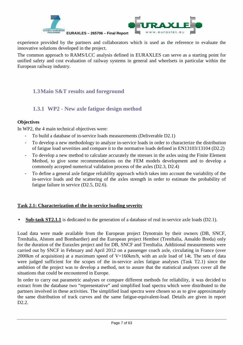
Method to generate virtual usages and applications: A method that enables to estimate the distribution of the in-service load severities for the reliability assessment of axles was proposed, based on the definition of elementary situations of an axle life and the generation of virtual load spectra. Fatigue-Equivalent-Loads associated to these virtual load spectra were calculated as well as the severity of the standard load (probability of having a Fatigue-Equivalent-load which is more severe than the standard load). The process was developed and applied to the SNCF passenger coach axle. The results are given in D2.2 and in Figure 2.
Figure 2 - Standardized load vs the distribution of virtual equivalent-loads for the SNCF axle.
Task 2.2: Axle calculation and fatigue analysis
A detailed description of the work described in the following section can be found in D2.3 and D2.4.
At the beginning of the project, a quick analysis of the state of the art enabled to define more precisely the technical objectives of the simulation activities within the project:
• to carry out Finite Element Analyses of axles, in order to calculate accurately the stresses, to validate the models by comparison with tests and finally to define general recommendations for the axles numerical modelling when using FEM techniques,
• to determine stress concentration factors in transitions and grooves and compare them to those defined in the standards EN1310X,
• to model whole wheelsets,
• to propose a numerical validation process of axles and wheelsets Validation of FEM models and general recommendations After defining the detailed geometries of the axles and both types of bench (Minden and Vitry) to be tested and simulated in WP2 and WP3, the numerical models were generated and analyses were performed by partners, for both trailer and motor axles.
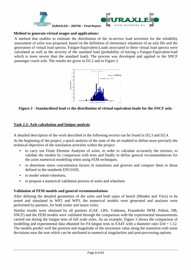
Similar results were obtained by all partners (CAF, LRS, Valdunes, Fraunhofer IWM, Polimi, DB, SNCF) and the FEM models were validated through the comparison with the experimental measurements carried out during the fatigue tests of full scale axles. As an example, Figure 3 shows the comparison of modelling and experimental data obtained for F4 fatigue tests in EA4T with a diameter ratio D/d = 1.12. The models predict well the position and magnitude of the maximum value along the transition with some deviations near the seat which can be attributed to numerical singularities and post-processing options.
EURAXLES – 265706 – Final Report
Page 10 of 63
Figure 3 - Model validation. F4. D/d=1.12. Modelling and experimental data comparison of Kt,ε
distribution along the transition.
From all the simulations performed in the project, general recommendations for axle simulations using FEM techniques could be given (deliverable D2.4). The main lines are summarized below:
• Finite element 3D or 2D with Fourier expansion models can be applied
• Element type: linear elements are relevant
• Element size: convergence analysis should be performed to check the validity of the models - If peak stress at R: typical size ≈ 4 mm
- If peak stress at r: typical size ≈ 1 mm
• Post-processing: - Unaveraged results are recommended to check convergence and effect of singularities
- A skin of membrane elements can be used to facilitate the analysis
• General design recommendation:
The peak stress should be located at the end of the transition (in R). To fulfil this recommendation, the transition length should comply the condition C > Cmin (see next section)
• Transitions: - Simple and adjacent transitions of seats with high interference (e.g. wheel and brake disc seats) can
be modelled using linearized models.
- For simple and sufficiently long transitions, analytical Kt values can be applied (see next section).
• Grooves Contact interaction (non-linear behaviour) is recommended to model the wheels, gears and brake discs with adjacent grooves (recommended friction coefficient = 0.6). Components with low interference and DN/D diameter ratios (bearings, labyrinths) can be removed from the models
The simulations and the tests showed that the two types of bench gave similar results.
It was also observed that the concentration factors related to transitions defined in the EN13103/13104 are lower than those obtained by FEM calculations (approximately 18-20% lower). Stresses in grooves derived from FEM were also found different from those obtained following the EN1310X rules. But in the meantime, experimental results from WP3 showed that the fatigue limits were underestimated in the standards, so that the current design process remains safe (as it can also be stated from return of experience from the field).

EURAXLES – 265706 – Final Report
Page 11 of 63
Parametric analysis of the stress concentration factor Parametric analyses were performed by CAF on simplified models to determine Stress Concentration Factors in transitions depending on geometrical parameters. The parametric analyses used Design of Experiments (DoE) methodologies due to the large number of the resulting combinations from all parameters considered. Formulas giving the stress concentration factors Kt,vm and the minimum length of the transition Cmin assuring that the maximum of stress occurs in the big radius could be identified (see D2.3).
For grooves, FEM analyses must be performed to evaluate the local stresses and the Kt factors.
Analysis of complete wheelsets Analysis of complete wheelsets has been also faced by the WP2 partners. The analysis covered different geometries and modelling approaches as follows:
• Geometries: Motor and trailer wheelsets.
• Finite Element Modelling: Linear and Non-linear 3D (CAF) and 2D Axisymmetric with Fourier’s series expansion (SNCF).
Axle numerical validation process In addition, several calculation methods have been studied and compared to the method defined in standards EN 1310X. From these analyses, an evolution of the validation process was proposed. It consists in:
• applying a bending moment and torque to the FE model in order to obtain the stress concentration factors in different sections of interest along the axle.
• calculating the stresses in the selected sections from the bending moments and torques obtained from the loads defined in EN 1310X using the beam theory.
• applying fatigue criteria as defined in EN 1310X. Table 1 summarizes the results obtained with the new method, including a comparison with EN 13104, with a motor axle made of EA4T (Figure 4). For the application of the new method, a fatigue limit in the axle surface based on local strains of 285 MPa estimated from the fatigue tests performed in WP3 has been applied.
Figure 4 - Motor axle. Definition of sections for the calculation.

EURAXLES – 265706 – Final Report
Page 12 of 63
Table 1 - Motor axle calculation. Results according to the new method and EN13104.
The following conclusions can be derived from the analysis:
• both methods give similar safety factors in the relevant sections.
• The new method tends to be more conservative in simple transitions.
• EN 13104 is more conservative in grooves.
• further investigations regarding the fatigue limits, especially for EA1N material, are still needed to completely close the assessment.
Proposal to complement EN 1310X As a result of the project, the main limitations of the current design standards EN 1310X have been identified and a complementary approach in order to provide designers with an additional method to avoid misunderstandings has been defined. This approach will be integrated in the Technical Report to be published by CEN. Basically, the method can be summarized as follows:
• Applied forces: According to the current EN 1310X
• Calculation of stresses acting on the axle: - Applying beam theory in the different sections of interest
- Stress concentration factors Kt in transitions:
- Based on strains as measured in the full scale tests: Kt,ε
- For simple transitions, analytical expressions derived in the project
- General: FE models of axles following recommendations derived in the project
• Allowable values: - Fatigue limits F1, F3/F4 derived from fatigue tests performed in WP3
- Safety factors: additional investigation needed
Task T2.3 : Reliability approach
Two different methods to assess the reliability of axles were developed: Polimi, starting from the EuroCode standard and the FKM guidelines, proposed a semi-probabilistic approach and SNCF applied the fully-probabilistic Stress Strength Interference Analysis approach to the axle.
More precisely, Polimi proposed a semi-probabilistic format that allows engineers to design axles with a target failure probability Pf=5x10⁻⁶ for a service life of 10 million km.
Section σ ba τ ta κ ε EF. κ γ ΕF. σ 1 σ 2 σ2 /σ1 σ=σ 1 - σ 2 σ allow SF K σ σ allow SF SF 1 /SF EN
1 65.08 0.00 1.26 1.15 82.02 0.00 0.00 82.02 285 3.47 1.012 65.88 240 3.64 0.952 77.19 0.00 1.47 1.26 113.44 0.00 0.00 113.44 285 2.51 1.05 81 240 2.96 0.853 125.17 5.23 1.52 1.29 190.18 -0.24 0.00 190.42 285 1.50 1.056 132.63 240 1.81 0.834 125.17 5.23 1.32 1.17 165.80 -0.23 0.00 166.03 285 1.72 1.056 132.63 240 1.81 0.955 85.22 3.53 1.26 1.17 107.78 -0.16 0.00 107.93 285 2.64 1.295 110.73 240 2.17 1.226 79.23 3.27 1.54 1.38 121.92 -0.17 0.00 122.09 285 2.33 1.678 133.4 240 1.80 1.307 78.02 -3.27 1.54 1.38 120.30 -0.17 0.00 120.46 285 2.37 1.678 131.37 240 1.83 1.308 82.75 -3.53 1.26 1.16 104.35 -0.16 0.00 104.51 285 2.73 1.295 107.55 240 2.23 1.229 127.39 -5.60 1.21 1.12 153.98 -0.25 0.00 154.23 285 1.85 1.018 130.25 240 1.84 1.00
10 88.29 -5.60 1.35 1.16 119.29 -0.35 0.00 119.64 285 2.38 1.018 90.61 240 2.65 0.9011 53.41 0.00 1.47 1.26 78.52 0.00 0.00 78.52 285 3.63 1.05 56.05 240 4.28 0.8512 45.06 0.00 1.26 1.15 56.79 0.00 0.00 56.79 285 5.02 1.012 45.59 240 5.26 0.95
Nominal stresses FE values Strain-based
Methodology 1 ΕΝ 13 10 4

EURAXLES – 265706 – Final Report
Page 13 of 63
The activity has dealt with different phases reported in details in D2.5: • an analysis of existing data for determining EA4T and EA1N S-N diagrams for fatigue damage
calculations;
• a summary of existing methods for calculating failure probability under fatigue; • the application of a semi-probabilistic approach, with an extensive Montecarlo simulation, for
determining the maximum allowable stress (partial safety factors) for a given axle made of A4T and A1N under service conditions identified by three different load spectra in order to ensure a target reliability
The safety factors have been determined adopting the format of FKM Guidelines (see Figure 5) as dependent on dispersion of fatigue properties and uncertainty of the load stress spectrum, so that they can be applicable if future datasets for fatigue limits for both steels will be available.
Figure 5 - Definition of the partial safety factor SF, in order to obtain a target axle failure
probability.
In parallel, in order not to use a “representative load spectrum” associated with several assumed coefficients of variation of the load, SNCF used the results obtained in Task T2.1 on the in-service load analysis in the framework of the Stress Strength Interference Analysis. This approach consists in performing a fully-probabilistic analysis, taking account of the scatter of the fatigue limits of the material (STRENGTH) and the variability of the load severities (STRESS) due to the variable axle usages. The method and the numerical tools were developed by SNCF and applied to the data associated to the SNCF passenger coach trailer axle. New simulations were carried out, using the final EA1N characteristics determined in WP3. The severity of the standard load defined in EN13103 was found equal to P1=3,6e-5 and the in-service probability of failure was estimated (Pf=3.e-8, Figure 6).
The overall approach (load analysis, characterization of the variability of the loads and the fatigue limits, stress calculations, reliability assessments) enables engineers to estimate the in-service probabilities of failure. It can also be used to evaluate the severity of the standard load. In the future, the method could also be used in specification: after defining the target probability of failure, the fatigue limit (mean value and scatter) can be specified.

EURAXLES – 265706 – Final Report
Page 14 of 63
Figure 6 - Reliability analysis of the SNCF passenger coach axle using the SSIA method.
1.3.2 WP3 - New testing methods of railway axle fatigue limit assessment The WP3 scope was to experimentally estimate fatigue limits of axles; such information is a main input in the design. The WP considered axles made in standard material (A1N and A4T) and defined a standard method for testing and analyzing the obtained data from a statistical point of view in order to be able in the future to apply the same method in the characterization of new materials or new surface treatments.
Axles conditions considered for the actual testing were axles in standard surface finishing for which axle body (free surface) was evaluated separately from axles seats where wheel, brake disc or bearing press fits take place; in this later case the coupling of the components can generate, when high bending is applied to the axle, relative micro sliding and derived friction forces that end up in local wear and possible micro cracks of the seat side surface; the phenomena is known as fretting corrosion and the result is that the fatigue limit is substantially lower than on the body. The severity of this phenomena is depending more on the geometry of the axle (seat-body diameter ratio) rather than on the material itself; for this reason different axle geometries were defined and tested. This part of the testing activity was complemented by task 3.3 dedicated to the theoretical modeling of fretting fatigue providing criteria’s for evaluating both the possibility for crack initiation and assessment of possible crack propagation. The aim was to provide tools for optimizing the design.
An important subject that was treated in WP4 concerns the study of possible solutions that can improve the axles surface protection from corrosion and for this some surface treatments techniques were proposed (shot pinning, increase roughness ecc); as similar solutions can have an effect on the surface fatigue limit; some solutions were verified in WP3 trough simple 1/3 scale axles and then in full scale conditions.
WP3 also tested corroded axles to verify the actual reduction of the fatigue limit.
A common testing procedure was defined in order that similar tests performed in different laboratories could produce comparable results.
A list of small scale and full scale tests and the relative drawings were defined and the wheelset manufacturing partners prepared the materials for the tests. All tests were performed by 7 partners of the Project in their laboratories.
Task 3.1 Scope of Task 3.1 was to define a common procedure for testing the fatigue properties of railway axles. Such activities was important in order to obtain results from the 7 different laboratories that can be

EURAXLES – 265706 – Final Report
Page 15 of 63
considered comparable; also the obtained results were put together with already existing data from previous projects in order to increase the statistical relevance of the final result.
This task result also was necessary as the testing method was relatively complex in terms of machinery used that was not standard and there was a risk for possible different interpretation of measured values and applied loads.
The common testing procedure was defined and is part of the Deliverable 3.1. The report is a result of a benchmark between the partners involved in the testing and that in the past years have accumulated experiences and methodology that slightly differ one from each other.
The procedure includes the definitions of different fatigue limits, methods for measuring and evaluating the stress applied, method for applying and controlling the load, roles for defining the load levels from one test to the next one (Stair case method) and finally the algorithm for statistically analyse the resulting data in order to estimate the average fatigue limit and the standard deviation (through the maximum likely hood method).
Task3.2 Body fatigue limit of standard surface F1 (transition and grove) A4T axles
The final analysis was made considering both the results of the Euraxle project and from the Deufrako project BMBF.
These results had a quite similar average value (around 204 MPa, Figure 7).
Figure 7 – Stair case fatigue test results of F1 A4T axles
Body fatigue limit (F1) of blasted surfaces
Two sets of 1/3 scale axles were prepared by RAFIL and tested by SNCF, the first series with final roughness of 3-4 µm Ra, the second series with roughness of 6-7 µm. The lower roughness shows a slightly lower fatigue limit than the higher roughness (340 and 363 MPa respectively). The reason for the difference must be due to the fact that the air pressure used for the blasting is increased to achieve the higher roughness and so the derived residual compressive stresses may be increased.
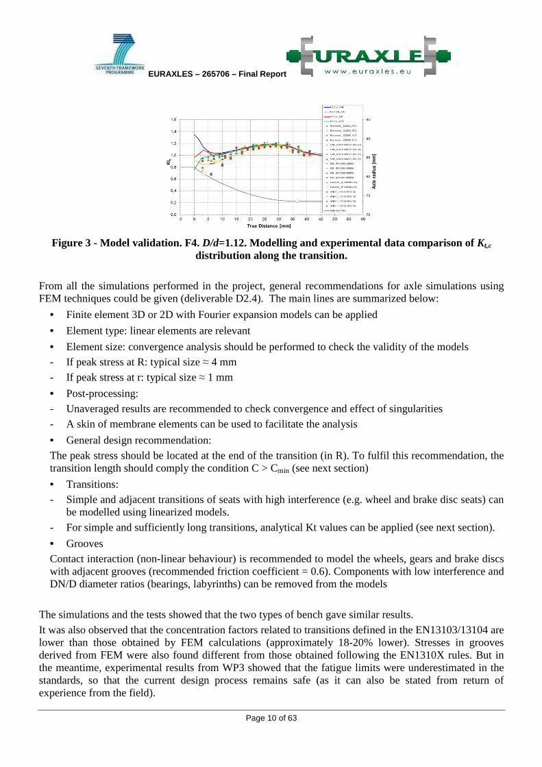
Full scale axle were blasted only with higher roughness 6-7 µm Ra and showed an average fatigue limit of 223 MPa (Figure 8).
EURAXLES – 265706 – Final Report
Page 16 of 63
Figure 8 - Stair case fatigue test results of F1 A4T axles blasted at a roughness of 6-7 µm Ra. The conclusion on this type of surface treatment is that the fatigue limit is not reduced compared do standard new surface and that it may be increased probably due to the compressive residual stresses.
Body fatigue limit of standard surface F1 (transition) A1N axles
The final analysis was made considering the results of:
• axles delivered by Valdunes to Polimi and tested on the Vitry type test rig • axles manufactured and tested by RAFIL on the Minden type test rig • axles tested In the BMBF Deufrako project in order to extend the number of test for a better
statistical evaluation The standard deviation of the results appears to be quite high due to the differences in the results of the lower results obtained on the Valdunes axles. The average fatigue limit is around 250MPa.

EURAXLES – 265706 – Final Report
Page 17 of 63
Figure 9 - Stair case fatigue test results of F1 A1N axles
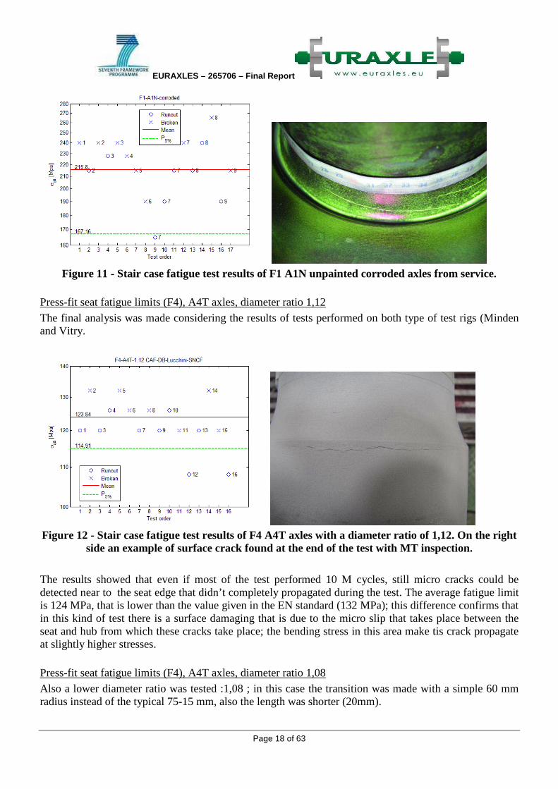
Body fatigue limit of unpainted corroded surface F1 (transition and grove) A1N axles from service
10 unpainted A1N axles that were in service for about 10 years on a passenger vehicle running 1 M km.
The results of the fatigue tests show a reduction of almost 14% of the average fatigue limit and an increase of about 18% of the standard deviation, respectively 216 and 24 MPa.
Figure 10 - A1N unpainted corroded axles from service.
EURAXLES – 265706 – Final Report
Page 18 of 63
Figure 11 - Stair case fatigue test results of F1 A1N unpainted corroded axles from service.
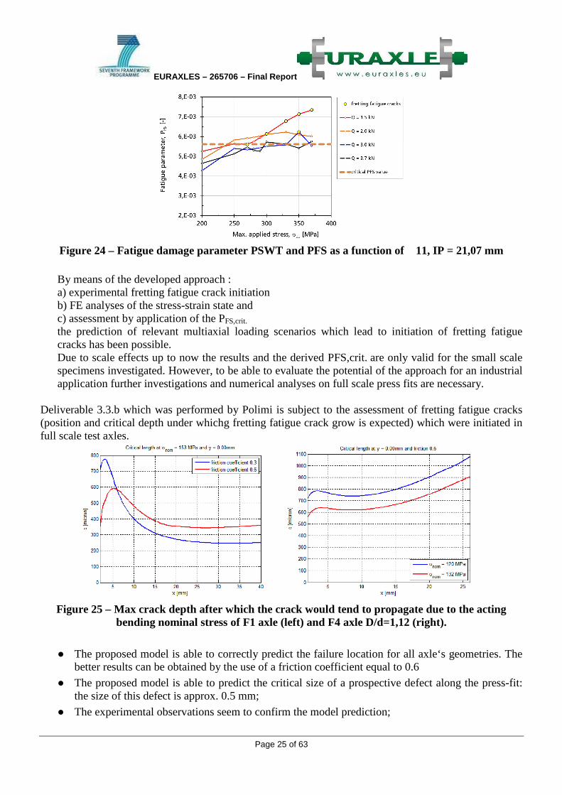
Press-fit seat fatigue limits (F4), A4T axles, diameter ratio 1,12
The final analysis was made considering the results of tests performed on both type of test rigs (Minden and Vitry.
Figure 12 - Stair case fatigue test results of F4 A4T axles with a diameter ratio of 1,12. On the right
side an example of surface crack found at the end of the test with MT inspection.
The results showed that even if most of the test performed 10 M cycles, still micro cracks could be detected near to the seat edge that didn’t completely propagated during the test. The average fatigue limit is 124 MPa, that is lower than the value given in the EN standard (132 MPa); this difference confirms that in this kind of test there is a surface damaging that is due to the micro slip that takes place between the seat and hub from which these cracks take place; the bending stress in this area make tis crack propagate at slightly higher stresses.
Press-fit seat fatigue limits (F4), A4T axles, diameter ratio 1,08
Also a lower diameter ratio was tested :1,08 ; in this case the transition was made with a simple 60 mm radius instead of the typical 75-15 mm, also the length was shorter (20mm).

EURAXLES – 265706 – Final Report
Page 19 of 63
The axles were tested on a Minden type; the results showed a higher average fatigue limit (146 MPa) than the 1,12 described previously (124 MPa); the reason is probably due to the higher slope in the 1,08 geometry axle, a higher slope appears to better reduce the local stress in the seat near to the edge.
Figure 13 - Stair case fatigue test results of F4 A4T axles with a diameter ratio of 1,08.
Experimental estimation of stress concentration factors
For all type of test, strain gauge measurements where made along the transition in order to determine the stress concentration factor; such measurements were then used inside WP2 to validate the FEM model for calculating the stresses along the transitions.
Figure 14 – Stress concentration factor Kt along the transition of the corroded axle (kt,max = 1,35).

EURAXLES – 265706 – Final Report
Page 20 of 63
Figure 15 - Stress concentration factor Kt along the transition of the F1 axles (kt,max = 1,20).
Figure 16 - Stress concentration factor Kt along the transition of the F1 axles (kt,max = 1,20),
modified by reducing the body in order to reduce the possibility of achieving cracks on the seat.

EURAXLES – 265706 – Final Report
Page 21 of 63
Figure 17 - Stress concentration factor Kt along the transition of the F1 axles (kt,max = 1,27), with
modified transition in order to reduce the possibility of achieving cracks on the seat.
Figure 18 - Stress concentration factor Kt along the grove of the powered axles.

EURAXLES – 265706 – Final Report
Page 22 of 63
Figure 19 - Stress concentration factor Kt along the transition of the F4 axles with D/d = 1,12
(kt,max = 1,18)

EURAXLES – 265706 – Final Report
Page 23 of 63
Figure 20 - Stress concentration factor Kt along the transition of the F4 axles with D/d = 1,08
(kt,max = 1,46),
Small scale tests to determine the Woheler curve A unique S-N diagram for EA4T, was calculated and derived from all the fatigue experiments onto small-scale specimens carried out by the two partners PoliMi and IWM within the Euraxles project. Specimens were extracted from full-scale axles manufactured by three producers across Europe, and tested. The calculation of the reference EA4T fatigue curve, was carried out by using the maximum log-likelihood method, adopting the concept of uniform scatter band. This reference S-N diagram was used for constructing a reference fatigue curves for railway axles, made of EA4T, in terms of local stress.
Figure 21 - S-N diagram for EA4T obtained merging data on small scale specs obtained by IWM
and PoliMI. After obtaining this S-N diagram, the variable amplitude tests carried out under block loading by PoliMi and IWM were re-analyzed. The average relative Miner index at failure has resulted to be very close to 0.5

EURAXLES – 265706 – Final Report
Page 24 of 63
Figure 22 - Distribution of Miner Index at failure (calculated with Miner Konzequent method) for
all the VA tests. Task 3.3 The main objective of Task 3.3 is to develop a method to improve the design of railway axles with nrespect to fretting fatigue. The deliverable was devided in two parts. Deliverable 3.3.a which was performed by Fraunofer IWM is subject to experimental and numerical studies of the initiation phase of fretting fatigue cracks on a small scale specimen level and the potential of such an approach to be applied to full scale axles .
Figure 23 – Schematic representation of the fretting fatigue test concept.
EURAXLES – 265706 – Final Report
Page 25 of 63
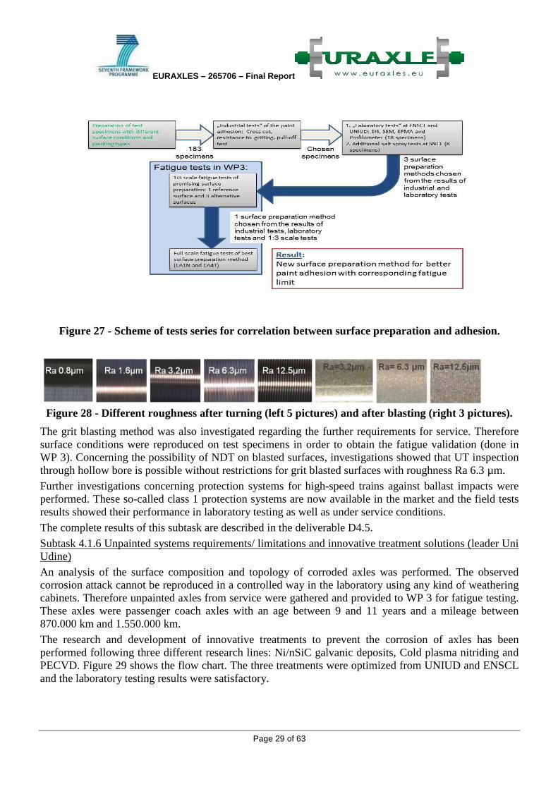
Figure 24 – Fatigue damage parameter PSWT and PFS as a function of �11, IP = 21,07 mm
By means of the developed approach : a) experimental fretting fatigue crack initiation b) FE analyses of the stress-strain state and c) assessment by application of the PFS,crit. the prediction of relevant multiaxial loading scenarios which lead to initiation of fretting fatigue cracks has been possible. Due to scale effects up to now the results and the derived PFS,crit. are only valid for the small scale specimens investigated. However, to be able to evaluate the potential of the approach for an industrial application further investigations and numerical analyses on full scale press fits are necessary.
Deliverable 3.3.b which was performed by Polimi is subject to the assessment of fretting fatigue cracks (position and critical depth under whichg fretting fatigue crack grow is expected) which were initiated in full scale test axles.
Figure 25 – Max crack depth after which the crack would tend to propagate due to the acting
bending nominal stress of F1 axle (left) and F4 axle D/d=1,12 (right).
● The proposed model is able to correctly predict the failure location for all axle‘s geometries. The better results can be obtained by the use of a friction coefficient equal to 0.6
● The proposed model is able to predict the critical size of a prospective defect along the press-fit: the size of this defect is approx. 0.5 mm;
● The experimental observations seem to confirm the model prediction;

EURAXLES – 265706 – Final Report
Page 26 of 63
● The predictions and the experiments clearly show that at the fatigue limit we can have the development of surface cracks which are then not able to propagate if they do not reach the critical size � new criterion for acceptance of run-outs.
Task 3.4 The following points were identified as relevant results to be considered for a future revision of the European norms. Axle transitions:
● As shown in WP2 Kt factors determined through FEM model are generally 20% higher than in the EN.
● Axle can still be calculated by the beam theory (EN 13103), but then apply the real Kt factors (FEM model).
● In this case local stress fatigue limits (as determined in this WP) should be used (with a failure probability of 5%).
● Further investigation should address the values of the safety factors to be used in the new calculation method; in the EN they depend on material, type of axle and include effects undetermined conditions of service loads and material strength scatter; methods developed in WP2 will allow to define appropriate values
● It is shown that appropriate surface blasting of the surface can ensure no reduction of the fatigue limit.
● It is shown that unpainted corroded axles have a 13% lower fatigue limit compared to new axles. Axle Press-fitted seats:
● It is proven that by applying the condition of acceptability that no crack indication should be found at the end of the fatigue tests, leads to a reduction of the F4 fatigue limits.
● Nevertheless permissible stress should not be changed due to the positive feedback from the service. The reason for the above is in the specific nature of the fretting fatigue phenomena (different from classical surface fatigue) which implies damages restricted to the surface.
● It is also shown that increasing the slope of the transition near the seat edge (and controlling the higher stress in this area) improves the fretting fatigue resistance of the press fitted seats.
1.3.3 WP4 - Tools, technologies and surface protection systems minimizing the negative influence of corrosion
State of the art and recommendation for improvement of the coating technology Basis for the work in Work Package 4 of Euraxles was the current state of axle corrosion protection. The state of the art was determined in 3 subtasks, each examining a different aspect of the current coating technology. Outcome of these subtasks was the derivation of current problems and possible improvements, but also of necessary requirements.
Subtask 4.1.1 Database on painting, coating and protection systems, process technology and its quality test methods (leader Bonatrans)
Existing solutions for new built axles and for maintenance were analysed by a survey among partners and operators. Content of the survey was the applied axle painting and protection systems including process and quality test methods. Furthermore technical specifications, literature and the outcome of recent

EURAXLES – 265706 – Final Report
Page 27 of 63
projects related to axle coating were searched to determine the state of the art. The results are described in deliverable D4.1 (leader Bonatrans).
Subtask 4.1.2 Analysis and limitations of the existing coating technologies and the quality assessment test methods contained in the standards (leader Rafil)
Problems in the past concerning painting and coating systems were analysed also by a survey among all partner, advisory groups and UIC experts. Limitations of the quality test methods according the EN standards and possible alternative or improved test methods were investigated. The deliverable D4.2 (leader Rafil) as a technical report describes the limitations of the requirements in the actual EN standards.
Subtask 4.1.3 Comparison of national requirements (e.g. maintenance rules & practices) and in- service operating conditions (leader Valdunes)
National requirements, maintenance rules and in-service operating conditions were compiled by a survey through all partners, advisory groups and UIC experts. The gathered information were analyzed and compared. The results are described in report D4.3 (leader Valdunes).
Results for state of the art:
The complete results of the work to determine the state of the art are reported in the three deliverables D4.1, D4.2 and D4.3 and also in a comprehensive report “Conclusion of Work Package 4, ERX-WP04-T-GHH-076-01”. Figure 26 shows an overview where the different parties see the main problems. The main results for general use of painting systems are:
Figure 26 - Reasons for problems with paint systems.
• A wide range of different types of paintings and coatings are used nowadays in the railway industry.
• In recent years a trend is apparent to reduce the consumption of paints containing VOC’s. • But only limited application of VOC-free, water based paintings. • There is not sufficient knowledge of the connection between paintings, the operating conditions
and the environment. • The liability of paint and coating systems need to be increased to prolong the lifetime of the
corrosion protection • SNCB use axles without painting or coating systems, and the axles do not have special problems
to corrosion fatigue
0%
10%
20%
30%
40%
50%
60%
70%
80%
90%
100%
cleaning / preparation of
the surface
roughness of the surface
adhesion of the coating
system
damages in service
long-time behaviour of
the coating system
expense for the
application of the coating
system
structure of coating
system / coating
thickness
testing of the coating
system in new built
condition
testing of the coating
system in maintenance
influence of roughness of
the surface on MT-and
UT-testing of the axle
Manufacturer
Operator
Research Institute

EURAXLES – 265706 – Final Report
Page 28 of 63
Furthermore general recommendations for quality test methods as basis for the improvement of European standard EN 13261 were derived:
• Tests should reflect the real conditions, must be repeatable and should be as simple as possible. • Test methods should be defined clearly and consistently • Tests from automotive industry can reduce costs, as they are commonly available. • The scope of application should be defined clearly: For homologation of painting system, for each
batch (production control) and/ or maintenance of axles.
Improvement of the axle corrosion protection Subtask 4.1.4: Benchmark of alternative and innovative protection solutions used in other industries (leader MerMec)
Alternative and innovative painting and coating solutions in other industries were investigated, especially of those industries with high demands to corrosion protection like e.g. marine. The found systems were analysed regarding service conditions, environmental impact, cost-effectiveness and approval aspects. The results of this assessment showed that only a few techniques deserve to be further investigated in order to check if they could be applied for wheelset axles. The complete results of the benchmark are summarized in the report D4.4.
Subtask 4.1.5: Investigation of new improved painting and protection systems and their technology requirements (leader ENSCL)
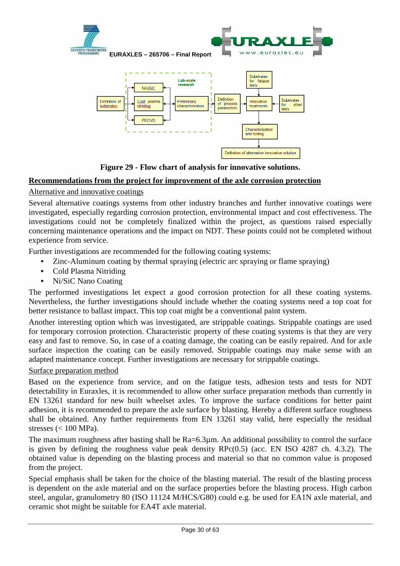
Conventional and new preparation conditions of axle surface were studied to provide a good adherence of coated systems and to find a correlation between the surface properties and the adhesion of the paint systems. Figure 29 shows the flow chart. Therefore 183 samples were prepared by Bonatrans, BVV, CAF, GHH, Lucchini and Valdunes (Figure 28), and analyzed in industrial tests. Further laboratory tests were carried out by ENSCL and UNIUD on selected specimens 16 different specimens to evaluate the protective properties of the coating systems and try to correlate them to the surface conditions. The correlation between surface preparation and adhesion tests were not clearly interpretable. The obtained results were mainly depending on the paint system. Only after the electrochemical tests some differences were observed between the samples. The most ameliorating effect was given by grit blasting. Further salt spray tests by SNCF underlined this result.
EURAXLES – 265706 – Final Report
Page 29 of 63
Figure 27 - Scheme of tests series for correlation between surface preparation and adhesion.
Figure 28 - Different roughness after turning (left 5 pictures) and after blasting (right 3 pictures).
The grit blasting method was also investigated regarding the further requirements for service. Therefore surface conditions were reproduced on test specimens in order to obtain the fatigue validation (done in WP 3). Concerning the possibility of NDT on blasted surfaces, investigations showed that UT inspection through hollow bore is possible without restrictions for grit blasted surfaces with roughness Ra 6.3 µm.
Further investigations concerning protection systems for high-speed trains against ballast impacts were performed. These so-called class 1 protection systems are now available in the market and the field tests results showed their performance in laboratory testing as well as under service conditions.
The complete results of this subtask are described in the deliverable D4.5.
Subtask 4.1.6 Unpainted systems requirements/ limitations and innovative treatment solutions (leader Uni Udine)
An analysis of the surface composition and topology of corroded axles was performed. The observed corrosion attack cannot be reproduced in a controlled way in the laboratory using any kind of weathering cabinets. Therefore unpainted axles from service were gathered and provided to WP 3 for fatigue testing. These axles were passenger coach axles with an age between 9 and 11 years and a mileage between 870.000 km and 1.550.000 km.
The research and development of innovative treatments to prevent the corrosion of axles has been performed following three different research lines: Ni/nSiC galvanic deposits, Cold plasma nitriding and PECVD. Figure 29 shows the flow chart. The three treatments were optimized from UNIUD and ENSCL and the laboratory testing results were satisfactory.
EURAXLES – 265706 – Final Report
Page 30 of 63
Figure 29 - Flow chart of analysis for innovative solutions.
Recommendations from the project for improvement of the axle corrosion protection Alternative and innovative coatings
Several alternative coatings systems from other industry branches and further innovative coatings were investigated, especially regarding corrosion protection, environmental impact and cost effectiveness. The investigations could not be completely finalized within the project, as questions raised especially concerning maintenance operations and the impact on NDT. These points could not be completed without experience from service.
Further investigations are recommended for the following coating systems: • Zinc-Aluminum coating by thermal spraying (electric arc spraying or flame spraying) • Cold Plasma Nitriding • Ni/SiC Nano Coating
The performed investigations let expect a good corrosion protection for all these coating systems. Nevertheless, the further investigations should include whether the coating systems need a top coat for better resistance to ballast impact. This top coat might be a conventional paint system.
Another interesting option which was investigated, are strippable coatings. Strippable coatings are used for temporary corrosion protection. Characteristic property of these coating systems is that they are very easy and fast to remove. So, in case of a coating damage, the coating can be easily repaired. And for axle surface inspection the coating can be easily removed. Strippable coatings may make sense with an adapted maintenance concept. Further investigations are necessary for strippable coatings.
Surface preparation method
Based on the experience from service, and on the fatigue tests, adhesion tests and tests for NDT detectability in Euraxles, it is recommended to allow other surface preparation methods than currently in EN 13261 standard for new built wheelset axles. To improve the surface conditions for better paint adhesion, it is recommended to prepare the axle surface by blasting. Hereby a different surface roughness shall be obtained. Any further requirements from EN 13261 stay valid, here especially the residual stresses (< 100 MPa).
The maximum roughness after basting shall be Ra=6.3µm. An additional possibility to control the surface is given by defining the roughness value peak density RPc(0.5) (acc. EN ISO 4287 ch. 4.3.2). The obtained value is depending on the blasting process and material so that no common value is proposed from the project.
Special emphasis shall be taken for the choice of the blasting material. The result of the blasting process is dependent on the axle material and on the surface properties before the blasting process. High carbon steel, angular, granulometry 80 (ISO 11124 M/HCS/G80) could e.g. be used for EA1N axle material, and ceramic shot might be suitable for EA4T axle material.

EURAXLES – 265706 – Final Report
Page 31 of 63
Unpainted axles
Unpainted axles (Figure 30) from service were investigated in WP4 regarding surface aspect, corrosion, roughness and chemical composition of the corrosion layer. The analysis showed that corrosion from service cannot be artificially reproduced in weather cabinets or chemicals, as the structure is too complex. For testing it is therefore recommended to use axles from service in the desired conditions.
Furthermore unpainted corroded axles from a passenger coach application were gathered for fatigue tests performed in WP3. From the results of the tests in WP3, the reduction of fatigue limit to 60% of the allowed value for unpainted axles seems to be very conservative. First estimations would allow a reduction to 80% to 85%. For detailed results and evaluation of the tests, see the report D3.2.
Figure 30 - Left: Unpainted axles for fatigue testing. Right: SEM micrograph through the corrosion layer
Task 4.2 Development a definition of appropriate quality test methods for painted/ treated protection and unpainted systems (leader DB AG) In this task possible new or improved quality test methods should be examined taking into account state of the art determined in WP 4 and the proposed improvements. Special remark was laid on standard test methods from other industries. The test methods currently in EN 13261 were critically analysed. The impact test was performed with different impact energies, and a new test method pull-off test was performed to evaluate the benefit of changes in the quality test methods for axle corrosion protection. The main outcome is a proposal for the improvement of testing methods in the standard for axles (clause 3.9 of EN 13261). The comparison of different test methods is summarised in D4.7 (leader DB AG).
Recommendations for testing methods of painting systems Proposal for changes in EN 13261 The product requirements for railway axles in Europe are described in the European standard EN 13261. Clause 3.9 describes the requirements for the protection against corrosion and mechanical aggression. Based on the results of WP4 and especially T4.2 the WP4 partners propose to make changes to clause 3.9 and related annexes which regard the protection against corrosion and mechanical aggression to improve the standard. The proposal will be given to the standardisation group CEN/ TC 256/ SC 2/ WG 11 as complete revised text with justification for each change. The complete revised text section is integrated in the document “Conclusion Work Package 4”.
Seven test methods are described in EN 13261 standard. For each test method it was discussed and decided with the WP4 partner and the members of the advisory group which changes will be proposed. For testing of coating thickness and resistance to specific corrosive products only editorial remarks are given.
Adhesion testing:
Steel
Corrosion
Resin

EURAXLES – 265706 – Final Report
Page 32 of 63
The adhesion is a characteristic of all adhesive forces applied between the coating and the axle surface. An alternative test method “Pull-off test” was investigated and already used in test series in ST 4.1.5. Based on this experience it is proposed to use the Pull-off test additionally for paint thickness greater 1000µm. The result should be a cohesion break with a minimum break force of 4 MPa.
Resistance to impact (for class 1 coatings):
This test method simulates a ballast impact. Currently EN 13261 requires impact energy of 11.3 J. This energy was assumed to be too low, as the impact energy of ballast stone of 60g at a speed of 200 km/h is 90J. Tests with impact energies of 50J and 90J were performed for 3 different commonly used class 1 coatings by DB and CAF. These tests were finished in the reporting period. The results were compared to real impacts from service. It was concluded that impact of 90J show comparable damages to the example from service (Figure 31).
Figure 31 - Left: Real ballast impact in service. Middle, right: Impacts with 50J and 90 J.
Resistance to gritting The actual EN 13261 standard describes a test procedure for the resistance to gritting which leads to high destruction of the paint system especially for paint systems with low thickness. A possible alternative is the test described in EN ISO 20567-1 method B “Determination of stone chip resistance” which is a common test method in automotive industry. As currently experience with this test is missing for railway axle paintings it can currently not be proposed to introduce the new test method in EN standard.
Resistance to salt spray The test duration needs to be defined. It is recommended to make the test duration depending from the coating class (480h, 750h or 1000h). Alternatively a second test method is proposed. It is the cyclic corrosion test and humidity test (DIN EN ISO 11997-1 cycle B), consisting of 6 Cycles. Each cycles contents 1 Day: Salt spray test (DIN EN ISO 9227), 4 days humidity test (DIN EN ISO 6270-2) and 2 days recondition at 18 – 28°C with 40 –60 % rel. humidity.
Resistance to cyclic mechanical stresses The test actually described in EN 13261 is very time and cost consuming. Alternative test methods were found, e.g. Bend test (cylindrical mandrel) according to DIN EN ISO 1519 (mandrel diameter 40 mm), Mendrel-flex test (EN ISO 6869) and Ericson test EN 1520. But the alternative methods only test the flexibility of the coating without cyclic bending. So it is not recommended to exchange the test method in the standard.
Furthermore a proposal is given for the standard EN 13261 for the scope of application of the above described test methods.
Testing of the cleanliness of the surface
The axle surface has to be properly cleaned before application of the coating. Different coating systems may have different sensitivity to the cleanliness of the surface. So the cleanliness to be reached is dependent on the used coating system.
The free surface energy is often used to express the cleanliness. If no special value for a painting system is defined by the supplier then 40 mN/m can be used as minimum value for most organic painting systems. Measuring of the surface energy can be done in several ways. For industrial production the usage of test inks is very convenient. Test inks are either available as fluid or as pens, and are easy to

EURAXLES – 265706 – Final Report
Page 33 of 63
handle in production process. Another method is the florescence measurement which is an optical method to evaluate the surface cleanliness without touching (and possibly polluting) the surface.
Fire protection
Organic paint system may be affected by fire. Therefore the topic fire protection is relevant also for wheelset axles. Fire protection is currently regulated in EN 45545-2 and TSI Loc&Pas, TSI HS and TSI Freight. The required test methods of TSI Freight and EN 45545-2 are different, whereas TSI Loc&Pas and TSI HS refer to national standards which will be replaced by EN 45545-2 in near future.
Members of the Euraxles project propose not to take any requirements concerning fire protection into EN 13261 as a further test for organic paint systems because rules already exist and because contradictions shall be avoided. Nevertheless testing of fire protection shall be harmonized for freight and passenger traffic. Based on the facts mentioned before the Euraxles project recommends changing EN 45545-2 as follows:
Wheel-sets (product category EX11) shall be tested against fire protection, if the thickness of an organic coating exceeds 300µm. In this case test shall be performed for the lateral spread of flames according ISO 5658-2:2006/Am1:2011, the limit shall be CFE ≥ 18 kW/m².
1.3.4 WP5 - Non- destructive testing (NDT) and verification of the reliability of axles in service
Task 5.1: Review of the current practice on NDT methods used for the verification of railway axles Task 5.1 of the EURAXLES project was dedicated to a review of the current practice on NDT methods applied in Europe for the verification of the integrity of railroad axles and to identify possible weaknesses in these methods. To reach this goal, in Subtask 5.1.1 of the project a questionnaire was distributed to the main operators, companies doing maintenance and also to train set and axle manufacturers with the request to describe the testing procedures applied in their maintenance facilities, including probe characteristics, calibration procedures, evaluation and experiences from the application in service.
Originally, the questionnaire was intended to deal with ultrasonic testing (UT) only, however since some operators don’t apply UT, use UT only as a complementary method, or use other NDT methods complementary to UT, also other NDT procedures were considered. Therefore, eddy-current testing (ET), magnetic particle testing (MT), and visual testing (VT) were included in the questionnaires both for hollow axle testing and solid axle testing. Altogether, 16 questionnaires were returned by 10 companies, among them 7 questionnaires for hollow axles and 9 for solid axles. The results of the questionnaire action are summarized in the first part of Deliverable 5.1.
The objective of Subtask 5.1.2 of the Euraxles project was to perform benchmark tests at which train operators and axle manufacturers took part with their inspection systems applied during fabrication or in service. The benchmark tests have been carried out only for ultrasonic testing since this is the predominantly NDT method. Originally it was planned to use cracked axles produced in the fatigue tests of WP3. However, since such axles were not available for the benchmark tests, it was decided by the project partners to use axles with artificial reflectors implemented in all relevant parts of the axles. The reflector types which were implemented are reflectors which are typically used for sensitivity setting for ultrasonic testing.
From May 3rd till May 5th, ultrasound experts from Deutsche Bahn, Lucchini, Renfe, Trenitalia and ULTRASEN met in the facilities of DB Systemtechnik in Brandenburg-Kirchmöser / Germany to
EURAXLES – 265706 – Final Report
Page 34 of 63
perform the benchmark tests at railroad axles with their ultrasonic equipment. Hollow axle testing was performed mainly using automated equipment, but also manual testing has been executed. Solid axle testing was done manually, by manual testing with mechanically guided UT probes, and with a semi-automatic system. CAF and GHH contributed to the benchmark tests in their own workshops after the axles have been dispatched to them after the Testing Week in Kirchmöser. The results of the benchmark tests are summarized in the second part of Deliverable 5.1.
The results of the questionnaire action and the experiences gained during the benchmark tests were evaluated in Subtask 5.1.3 with respect to strengths and weaknesses of the presently applied inspection systems and practices. On the basis of this analysis, suggestions for improvements have been given, which are shortly summarized as follows:
Replacement of manual testing by automated testing to ensure reliability and repeatability, reduce human errors, improve throughput, allow for automatic documentation and data storage
Improvement of sensitivity without increasing the false calls rate
Differentiation between critical and non-critical surface imperfections
Consideration of the true axle geometry in order to reduce the dead zone near the outer surface or eliminate echoes coming from assembled components in case of press fit
Differentiation between geometrical echoes and defect echoes
Application of high-resolution data acquisition to reduce the dead zone near the outer surface and to classify defects
The detailed analysis is accessible in Deliverable 5.3.
Task 5.2: New methods to inspect axles in real service condition Based on the “Gap Analysis”, the intention of Task 5.2 was to propose possible improvements of the NDT methods applied during maintenance or to propose new methods for in-service inspection. Various improvements have been identified which show potential to increase the reliability of ultrasonic testing of hollow axles and solid axles. Such improvements have to consider the most critical areas in both axle types.
It has been also presented a non-destructive technique of Inspection based on a Laser emission in Deliverable 5.2. It highlighted background and constraints of the laser - ultrasound methodology when applied by the railway industry to track inspection purposes.
After these generalities, a description of the system design already developed has been given. This description was enhanced by some meaningful laboratory and real ground test results that the system is characteristics of. The report concluded with an analysis on the feasibility and convenience of transferring these previous achievements of the laser – ultrasound methodology, from in operation track inspection to axle’s inspection purposes.
The focus of Task 5.2 was on advanced UT techniques but also alternative or supplementary techniques were considered, like thermography and application of sensors for structure-borne sound and acceleration sensors.
The following technologies and methods, suitable to improve the presently applied inspection techniques were outlined and discussed in detail in Deliverable 5.5:
• Ultrasonic phased array technique • Synthetic Aperture Focusing Technique (SAFT)

EURAXLES – 265706 – Final Report
Page 35 of 63
• POD simulation • Induction thermography for surface crack detection • Condition monitoring
The phased array technique is already widely used for automatic ultrasonic testing of solid axles in heavy maintenance, especially from the cylindrical part of the axles. But also for testing from the end face phased array probes are applied and can provide considerable advantages compared to end face testing with conventional probes. A new phased array method, the so-called Sampling Phased Array (SPA) together with a special noise elimination algorithm (eRDM) allows a considerable increase of the signal-to-noise ratio compared with the conventional phased array technique. The benefits of SPA are particularly apparent in the case of testing of assembled and coated axles using the high angle scan technique. This is of special interest for axle testing on the train in light maintenance where removal of the coating at the contact surface of the ultrasonic probes is not convenient. With the new technique high angle scanning on the train becomes possible and it is able to save time and costs. Using such transportable and flexible equipment for the 100 percent inspection of solid wheel set axles could provide an economical alternative to stationary inspection systems.
For hollow axle testing, presently research activities are performed by DB, aiming to combine the phased array technique with the SAFT method for analysis of ultrasonic indications found during routine inspection. The combination of both methods allows distinguishing between false indications and cracks by the calculation of reconstruction images showing the geometrical indications and in case of a crack, the crack tip signal. The differentiation between cracks and false indications is important to avoid disassembly of an axle in case of indications whose cause is unclear. In this way hollow axle testing becomes much more efficient. Additionally to classification of ultrasonic indications, sizing of detected cracks is possible by evaluating the crack-tip signals for cracks from about 2 mm depth.
The defect detection capability of an inspection method can be characterized by its probability of detection (POD). However, experimental determination of the POD is very time-consuming and costly. To reduce the efforts for POD determination, simulation tools are an appropriate means. If the POD for the applied inspection technique is known, inspection intervals can be optimized and established less conservative. Generally, simulation tools are very convenient to optimize an inspection technology and to support the validation process.
Besides ultrasound, magnetic particle testing (MT) is used for axle inspection, especially for solid axle testing. However, so far MT indications must be evaluated visually why currently no fully automatic system exists. Moreover, MT requires a fluorescent particles liquid which has to be disposed after the inspection. These disadvantages can be overcome by induction thermography which can be easily automated which is the prerequisite for further processing of the recorded thermography data to achieve suppression of disturbing influences and to exploit the additional information provided by the temporal changes of the thermographic image sequence.
For future maintenance concepts it is desirable to go from the regular maintenance to a condition-based maintenance. From the safety aspect, the most important objective is the timely warning before a critical defect results in an axle failure, which can be achieved by on-line monitoring which is also an appropriate means to record unexpected singular events which might cause damages which are not considered in the calculation of the axle’s lifetime. Possible approaches to fulfill this task are integrated ultrasonic probes or sensors recording the structure-borne sound together with the information gathered from acceleration sensors.

EURAXLES – 265706 – Final Report
Page 36 of 63
Task 5.3: Diagnosis of flawed axle using new analysis and classification techniques
The aim of this task is to describe a new methodology of diagnosis and classification of flaw axles proposed by the University Carlos III of Madrid (UC3M), which tries to be the seed of a new robust NDT method for axle inspection that could be classified as a condition based maintenance technique. This method is based in a sophisticated signal processing procedure that uses vibration signals obtained during rotation of the axle.
At first place, through the use of an analytical model, phenomena occurring in vibration signals when a crack appears were analyzed. The model selected was the widely accepted Jeffcott Rotor model, including a breathing function. With this model, the theoretical acceleration occurring in the middle of the axle is obtained. It was concluded that the amplitude of the signal at the first, second and third harmonic of the rotating speed increases significantly with the crack size. This phenomenon was observed at all the rotation speeds tested.
Afterwards, experimental analyses were carried out in scaled axles, mounted in a rig called Rotokit. Vibration signals were obtained from a railway axle scaled to 1/8. The chain measurement allows getting real vibration data. The tests were carried out in different conditions of rotation speed, and of crack level. The rotation speeds are:
• 20Hz (1200 rpm) • 40Hz (2400 rpm) • 60Hz (3600 rpm)
The different crack levels were always located in the middle section of the axle. Their values, attending to the damaged area, were:
• Healthy axle. • Axle with a crack of 12.5% of the diameter of the axle. • Axle with a crack of 25%. • Axle with a crack of 50%.
The results of diagnosis were very promising and were shown in deliverable 5.4.
With the good results obtained in this first approximation, the experimental setup was improved and the number of levels of crack was increased to 9. The database generated in this case was composed of experimental data obtained from three different axles installed in Rotokit. Each case of crack and speed was tested 12 times, where each test consists of 100 consecutive measurements, in order to reduce experimental errors. Finally, the database generated had 432.000 points in the time domain.
The pattern selected as optimal to detect cracks in axles in this task was the Wavelet Packets Transform (WPT) which was used to train different Neural Networks (NN). The architecture of NN finally chosen has been the Radial Basis Function (RBF), because both the computational cost and hit rates were optimized.
The new 9 levels of crack, again located in the middle section were:
• Healthy axle. • Level 1: axle with a crack of 3.12% of the diameter of the axle. • Level 2: crack of 6.25% of the diameter.
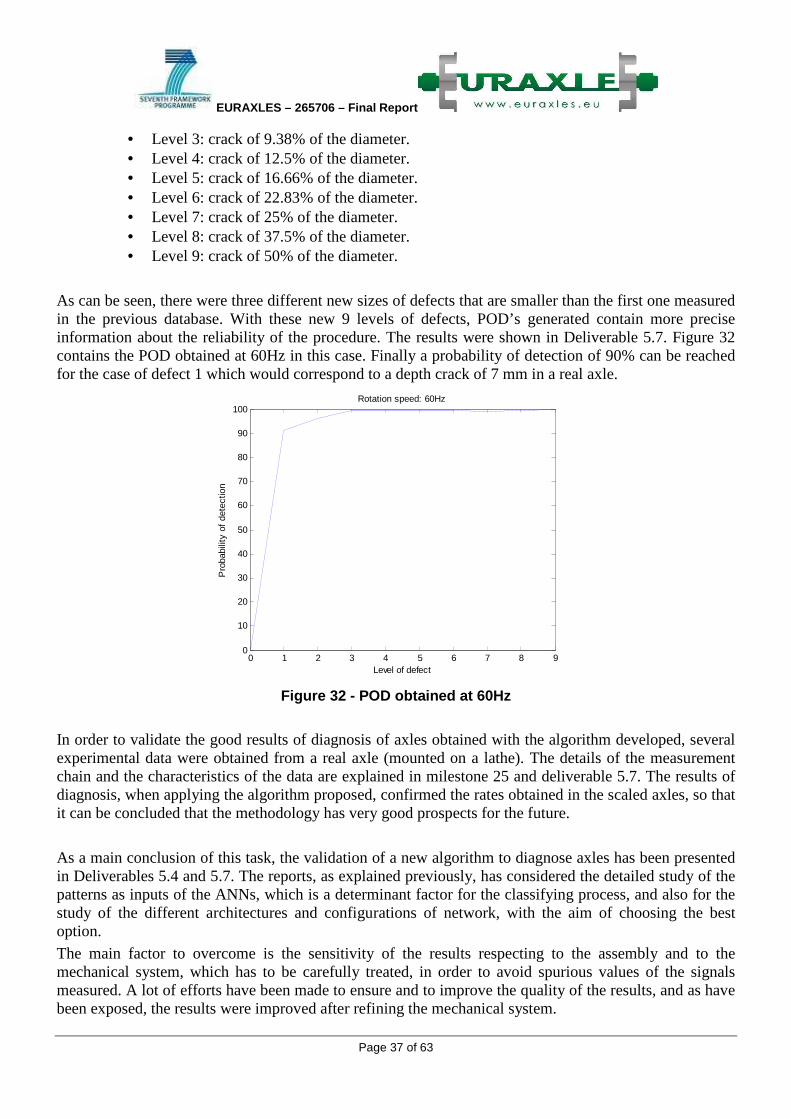
EURAXLES – 265706 – Final Report
Page 37 of 63
• Level 3: crack of 9.38% of the diameter. • Level 4: crack of 12.5% of the diameter. • Level 5: crack of 16.66% of the diameter. • Level 6: crack of 22.83% of the diameter. • Level 7: crack of 25% of the diameter. • Level 8: crack of 37.5% of the diameter. • Level 9: crack of 50% of the diameter.
As can be seen, there were three different new sizes of defects that are smaller than the first one measured in the previous database. With these new 9 levels of defects, POD’s generated contain more precise information about the reliability of the procedure. The results were shown in Deliverable 5.7. Figure 32 contains the POD obtained at 60Hz in this case. Finally a probability of detection of 90% can be reached for the case of defect 1 which would correspond to a depth crack of 7 mm in a real axle.
Figure 32 - POD obtained at 60Hz
In order to validate the good results of diagnosis of axles obtained with the algorithm developed, several experimental data were obtained from a real axle (mounted on a lathe). The details of the measurement chain and the characteristics of the data are explained in milestone 25 and deliverable 5.7. The results of diagnosis, when applying the algorithm proposed, confirmed the rates obtained in the scaled axles, so that it can be concluded that the methodology has very good prospects for the future.
As a main conclusion of this task, the validation of a new algorithm to diagnose axles has been presented in Deliverables 5.4 and 5.7. The reports, as explained previously, has considered the detailed study of the patterns as inputs of the ANNs, which is a determinant factor for the classifying process, and also for the study of the different architectures and configurations of network, with the aim of choosing the best option.
The main factor to overcome is the sensitivity of the results respecting to the assembly and to the mechanical system, which has to be carefully treated, in order to avoid spurious values of the signals measured. A lot of efforts have been made to ensure and to improve the quality of the results, and as have been exposed, the results were improved after refining the mechanical system.
0 1 2 3 4 5 6 7 8 90
10
20
30
40
50
60
70
80
90
100
Pro
babi
lity
of d
etec
tion
Rotation speed: 60Hz
Level of defect

EURAXLES – 265706 – Final Report
Page 38 of 63
After getting very encouraging results both in scaled and real axles in rigs, there is still a lot of work to do. Carrying out some tests in a real railway during its operating condition would be the next step. This would allow the study of critical parameters, as the influence of the signal/noise ratio (SNR) in the reliability of the system, and the amount of time remaining from the detection of the crack to a catastrophic failure. These parameters need still to be determined, though the first results give reasons for being optimistic, that is why the research is ongoing.
Task 5.4: Verification of influence of surface damage and corrosion in service Corrosion fatigue is a common damage mechanism in wheelsets. To what extend corrosion is leading to axle failure is not known in the sense that it was never ascertained what the size of a localized corrosion defect (e.g. corrosion pit) should be to lead to failure by corrosion fatigue. It is moreover difficult to indicate a preferential initiation area since many axle geometries and loading conditions exist in the European train fleet. In this task NDT techniques are reviewed for monitoring of corrosion and cracking in train axles without the need of disassembly.
For the detection of corrosion underneath organic coatings a range of non-conventional NDT techniques were reviewed. Since corrosion results in the roughening of surfaces, main focus was put on optical NDT techniques. Promising NDT techniques are terahertz radiation technology (THz), electronic speckle pattern interferometry (ESPI), digital speckle correlation (DSC) and digital fringe projection (DFP). Although these NDT techniques enable corrosion detection, their applicability to assess degradation phenomena under coated areas or in interference areas must be carefully assessed mainly when considering full-size train wheelsets. Specific challenges to be addressed in the assessment of these NDT techniques relate to: (1) limited accessibility to the coated areas due to the amount of components mounted in the axles and (2) inaccessibility to the interference area and similarity of the dielectric properties of the corrosion products and the substrate present at the interference areas.
The ultimate objective is to assess the potential of NDT technologies that can be used without disassembling the components mounted in the axle. In this context, Electrochemical Impedance Spectroscopy (EIS) and advanced ultrasound Lamb or Rayleigh wave (Lamb wave) are considered for testing in full size train axles.
The feasibility of using EIS for monitoring of surface damage in the interference area was studied. EIS is based on the application of a sinusoidal voltage signal between a work electrode and counter electrode and subsequent measurement of the resulting current response. This is done for a range of applied voltage frequencies. The ratio of applied voltage to current response is the impedance of the path between working and counter electrode. In a bode plot the impedance values for different applied frequencies is represented. In the studied system, the working electrode is the axle surface and the counter electrode is the wheel. EIS experiments and simulations of the bode plot for different % of damaged area of the interference area, in the absence of humidity, indicated that significant surface damage is needed to provide a major decay in the EIS response. Moreover the ingress of humidity or aggressive species at the interference gap results in similar dielectric properties for the damaged area and non-damaged areas.

EURAXLES – 265706 – Final Report
Page 39 of 63
These results let conclude that EIS, in the studied setup, is of limited use for assess of the surface condition in the interference area.
For detection of fatigue cracks lamb wave testing was considered as a promising technique. A theoretical feasibility study was performed that indicated that lamb wave testing can be used to detect cracks in non-covered parts of the train axles. Since cracks in an axle at rest are typically closed, the cracks have little effect on passing acoustical waves. When the train is moving the cracks periodically open up so that interaction with wave packets becomes more significant. Observables like mode conversion of the waves, reflection and transmission amplitudes and frequency of the signal allow the detection of cracks and indication of the defect location. Parts like wheels, bearings, mounted onto the axle are in contact with the surface which implies that it is very unlikely that covered defects can be detected by means of surface waves due to very complex interactions in these areas. Regarding the set-up, a pulsed laser system is preferred above a piezoelectric set-up. Not only is it a non-contact technique, it only required two laser points and at maximum one displacement system to inspect the axles of a whole train. It is indeed possible to guide a light signal through fiberglass cables to the desired location. This way one laser system could allow inspection of a large number of wagons. To gather as much data as possible during the opening up of a crack two approaches are suggested: sending in a sufficient number of wave packets during each loading cycle or a stroboscopic method where the inspection system is accurately coupled to the rotation of the train axle.
Finally a novel crack detection method was investigated. It was investigated whether elastoresistive deformation plugs could be used to detect cracks in hollow train axles using the above mentioned EIS technique. This novel monitoring technique is essentially an in-line technique and is based on the expectation that train axles containing cracks or corrosion pits show a different vibration behavior compared to intact train axles. It is the purpose of this study to investigate whether different vibration behavior can be detected through the measurement of impedance of elastoresistive plugs inside the train axle. Elastoresistive materials typically consist of a non-conductive matrix with conductive fillers. When these materials are compressed, the conductivity increases. When the filler concentration increases beyond a so-called percolation threshold, the conductivity drastically increases since more conductive paths/networks are formed in the material. Ideally a concentration near the threshold is used for maximum sensitivity of the material to small compression. Since commercially available elastoresistive materials did not have the right properties needed for this application (sufficient elasticity, no creep, hysteresis and nonlinear response) tailor-made materials were investigated and developed. A combination of dielectric firm gel (silicone) in combination with carbon black filler with diameter 5 µm gave the best results. Experiments with a scale model of a train axle (1:5) and the use of a electrodynamic shaker indicated that a change in resistance of the plugs could be measured under dynamic loading. Comparison of the results of testing on a scale model with and without crack yielded no conclusive results since the relaxation time of the elastoresistive material in the tube without defect was significantly smaller than for the tube with defect. Therefore further efforts should focus on comparison of the EIS impedance spectrum with defect and without defect under dynamic loading and on examination of the sensitivity of this technique by comparing the results for tubes with different defect sizes. Furthermore the reproducibility of the plugs can be improved.
1.3.5 WP6 - RAMS and LCC taking into account market uptake
The application of RAMS/LCC concepts in the railway sector is still incipient and the usual rule is that each organisation applies self-developed technologies which may differ from one to another. As a first step in the Euraxles project, a survey of RAMS/LCC techniques used in the railway sector has been

EURAXLES – 265706 – Final Report
Page 40 of 63
performed. The aim has not been to do an exhaustive revision of the state of the art in RAMS/LCC technologies but to identify the standards most frequently used which would be adopted as a basis to establish a unique analysis tool.
A questionnaire has been distributed among the WP6 participants. The questions concerned RAMS/LCC techniques applied, software, standards and databases. In general, it can be said that most of the participants consider RAMS/LCC analysis as part of their activity and in the contracts but to a different extent. The most relevant conclusions are:
- Most of the participants calculate RAMS/LCC regularly and some have RAMS specialists in the company.
- Operators consider RAMS/LCC requirements in their contracts for the complete vehicle but not specifically for the wheelsets. Integrators specify RAMS/LCC parameters in the contracts including the wheelset which are then translated to the manufacturers.
- In the vast majority, the participants use their own databases to manage the RAMS/LCC parameters.
- There is a lack of feedback from operators and maintainers to manufacturers. This fact is one of the main difficulties to improve the railway transport competitiveness.
- In many cases, the tools and information given by the manufacturers are provided by the customers so they are considered as confidential.
- Most participants use their own RAMS analysis software (basically Excel).
From the results of the survey, a RAMS/LCC tool has been defined based on the following basic requirements:
- Excel tool - FMECA should be considered for safety analysis. - For LCC calculations, acquisition and operational costs should be considered as they represent the
most relevant phases affecting the LCC of axles. - Maintenance costs should cover both preventive and corrective maintenance.
Concerning safety, it has been agreed within the project that the analysis should be based only on the RPN (Risk Probability Number) as a combination of severity, detectability and frequency for assessing the level of risk based on the outcome of the FMECA analysis. This option has been also discussed with the UIC Set 06 EN 50126 project (www.uic.org) and it is in line with the work performed by the Joint Sector Group linked to the freight wagon maintenance1 in which a Fault Tree Analysis (FTA) of a wheelset is included.
Thus, FMECA is applied to categorize the failure modes and effects and to prioritize efforts and it is a common opinion that a target value for RPN to determine quantitatively the risk is not attainable at this moment due to the lack of accurate data from service. However, this analysis should be the basis for the future to get accurate data for risk calculation.
Several questionnaires have been prepared and distributed amongst the partners to collect data based on the common tool in order to define the parameters for the reference cases which will be used for the comparative analysis of the different solutions investigated in the project. The reference cases chosen include wheelsets from Freight, High speed, Passengers/EMU/DMU and Loco.
It has been found that the available data coming from the return of experience is limited, specially referring to reliability data of axles. The improvement of collecting rata related to the reliability of axles is clearly a need for the future in order to identify the key aspects for the optimization of safety of axles in the future. As an alternative, public available data coming from databases have been analyzed. The results of the study show that the safety of the European railway system has continuously improved along the 1 JSG final report on the activities of Task Force for Freight Wagon Maintenance, 20/12/2012, (http://www.jsgrail.eu)

EURAXLES – 265706 – Final Report
Page 41 of 63
last decades and nowadays railway transport is extremely safe. For example, Figure 33 shows the number of axle breaks in Germany in the last 50 years as reported by the Joint Sector Group work on Freight Wagons1.
Figure 33 - Number of axle breaks per billion wheelset kilometres between 1960-2010 in Germany1. Due to the lack of quantified data, the reliability of axles has been estimated by means of information provided by experts in maintenance within the different contributing companies. From the received data, the costs related to corrective maintenance accounts for less than 5% of the total LCC so it has been decided to perform the LCC analysis considering only the preventive maintenance operations.
The collected data features a significant scatter of maintenance rules both among the contributors and applications considered. This result shows a lack of harmonization of maintenance rules in Europe. Collaboration between different companies involved in the supply and maintenance of axles is needed for further optimization of safety and LCC of these components.
The collected data has been analysed by all WP6 partners and reference cases for each application in terms of maintenance operations, intervals and associated costs have been defined. Afterwards, and applying the LCC calculation tool developed in this work package, life cycle costs (LCC) analyses of these reference cases have been performed. A summary of the results is presented in Table 2 in which the representative annual mileage, lifetime, annual Net Present Value (NPV) and NPV/1,000 km are included. The cost distributions are graphically represented in Figure 34.
FREIGHT HIGH SPEED LOCO EMU Mileage/year 30.000 km 350.000 km 150.000 km 175.000 km
Lifetime 40 years 30 years 30 years 30 years NPV annual 139 € 1.766 € 1.106 € 828 €
NPV / 1.000 Km 4,62 € 5,04 € 7,38 € 4,73 €
Coating Class 3 Class 3 (2 comp) Class 3 Class 3
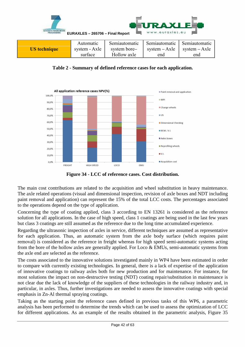
EURAXLES – 265706 – Final Report
Page 42 of 63
US technique Automatic
system - Axle
surface
Semiautomatic
system bore–
Hollow axle
Semiautomatic
system – Axle
end
Semiautomatic
system – Axle
end
Table 2 - Summary of defined reference cases for each application.
Figure 34 - LCC of reference cases. Cost distribution.
The main cost contributions are related to the acquisition and wheel substitution in heavy maintenance. The axle related operations (visual and dimensional inspection, revision of axle boxes and NDT including paint removal and application) can represent the 15% of the total LCC costs. The percentages associated to the operations depend on the type of application.
Concerning the type of coating applied, class 3 according to EN 13261 is considered as the reference solution for all applications. In the case of high speed, class 1 coatings are being used in the last few years but class 3 coatings are still assumed as the reference due to the long time accumulated experience.
Regarding the ultrasonic inspection of axles in service, different techniques are assumed as representative for each application. Thus, an automatic system from the axle body surface (which requires paint removal) is considered as the reference in freight whereas for high speed semi-automatic systems acting from the bore of the hollow axles are generally applied. For Loco & EMUs, semi-automatic systems from the axle end are selected as the reference.
The costs associated to the innovative solutions investigated mainly in WP4 have been estimated in order to compare with currently existing technologies. In general, there is a lack of expertise of the application of innovative coatings to railway axles both for new production and for maintenance. For instance, for most solutions the impact on non-destructive testing (NDT) coating repair/substitution in maintenance is not clear due the lack of knowledge of the suppliers of these technologies in the railway industry and, in particular, in axles. Thus, further investigations are needed to assess the innovative coatings with special emphasis in Zn-Al thermal spraying coatings.
Taking as the starting point the reference cases defined in previous tasks of this WP6, a parametric analysis has been performed to determine the trends which can be used to assess the optimization of LCC for different applications. As an example of the results obtained in the parametric analysis, Figure 35

EURAXLES – 265706 – Final Report
Page 43 of 63
shows the estimated LCC variation for high speed applications when the intervals for different maintenance operations are changed taking as the initial situation the corresponding reference case. As can be seen, the highest influence is related to the heavy maintenance (H.M.) operations which, among others, include the substitution of wheels and the paint removal for MPI inspections. Similar analyses have been performed for other parameters like US techniques and types of coatings. Studies of the other selected applications (Freight, Loco and EMUs) have yielded analogous results. The obtained curves can be used to estimate the cost savings when modifications on the maintenance practices are considered.
Figure 35 - LCC parametric analysis results. High speed.
The investigations carried out in the Euraxles project have been combined to assess, in a first attempt, the maintenance practices in order to ensure the target reliability of axles in service. In general terms, the aim of any maintenance should be to preventively avoid any problem related to deterioration of the axles in service and, more specifically to the axle surface and coatings, to 'maintain the original surface condition' of the axle. A methodology for the reliability and cost analysis of the axles has developed considering mechanical impacts and corrosion as the failures affecting the reliability of the axle which can be found on service.
The methodology has been applied to a high speed application as a demonstrator taking as the basis the maintenance information related to the reference case for this particular application and the load spectrum extracted from the HYPERWHEEL project.
Figure 36 shows an example of the attained results. In this case, both the average failure rate and the annual cost as a function of the inspection intervals (an annual mileage of 350,000 km has been considered) of an axle subjected to corrosion for a maximum stress of 210 MPa acting on the axle are represented. It can be seen that the inspection interval to achieve the target failure rate is 70,000 km. Concerning the cost calculation, which accounts for the cost of maintenance and the potential cost related to a derailment, the optimal minimum cost is obtained for an inspection interval of 70,000 km too.
Analogous calculations have been done for different situations and the main conclusion which can be derived is that the inspection intervals depend on the applied stress so that the higher the acting stress the smaller the inspection interval required to reach the target failure rate and, conversely, the higher associated costs.

EURAXLES – 265706 – Final Report
Page 44 of 63
a) Failure rate b) Annual cost
Figure 36 - Reliability and cost analysis of and axle subjected to corrosion. Failure rate and cost vs. inspection intervals for a maximum stresses = 210 MPa.
The main conclusions of the tasks performed in WP6 are highlighted below:
- According to the return of experience, the risk to have axle failures in actual railway traffic is very low so the railway transport is extremely safe.
- There is a significant scatter of maintenance practices among the different companies showing the lack of harmonization of maintenance rules in Europe.
- Information about reliability of axles in service is lacking. Collaboration between different companies involved in the supply and maintenance of axles is needed for further optimization of safety and LCC of these components.
- The main cost contributions to LCC of axles are related to the acquisition and wheel substitution in heavy maintenance. The percentages associated to these operations depend on the type of application.
- The axle related operations can represent 15% of the total LCC costs, depending on the application.
- There is a lack of expertise of the application of innovative coatings to railway axles both for new production and for maintenance. Thus, further investigations are needed to assess the innovative coatings with special emphasis in Zn-Al thermal spraying coatings.
- A method for risk analysis linked to cost calculations for determining the optimal inspection intervals has been derived. The resulting intervals depend on the maximum stress of the load spectrum.
The common approach to RAMS/LCC analysis defined in EURAXLES can serve as a starting point for unified safety and cost evaluation of railway systems in general and wheelsets in particular within the European railway industry.
EURAXLES – 265706 – Final Report
Page 45 of 63
1.4 Potential impacts A high impact from the different solutions and recommendations from the project is expected in the following technical areas, highlighted at the inception of the project.
• Optimised axle design The project has proposed a new axle design methodology based on modern analysis techniques and appropriate safety limits derived from calculated and tested loading scenarios of vehicles in service. The new optimised design method will enable the axle to adequately withstand the applied loads leading to reduced axle degradation, thus reducing the risk of axle failure and vehicle accidents. This specific activity carried out in the project has been presented in the spring 2014 to CEN (European Committee for Standardization). The committee responsible for the standardization of railway rolling stock, in more specifically in the field of Wheels and Wheelsets had decided to officially start working on the publication of a CEN “Technical Report”. This report will use the key results of this activity in order to prepare the grounds for future standardization work.
• New coating solutions Fatigue cracks causing axle failures are a major cause of accidents, and two recent events (in Italy and Germany) highlight this link. Current organic based coatings are particularly susceptible to degradation from the environment and ballast impact. The project will develop a more robust coating system (through the investigation of various innovative coatings) ensuring axle projection and hence improved fatigue resistance. This will significantly reduce the likelihood of axle failure and axle failure induced accidents, thus reducing the number of fatalities and injuries caused.
• Better detection of defects Improved detection of defects will be enabled through an improved/innovative NDT methodologies which will permit more accurate measurements of the axle condition and detection of defects. The technology will detect possible defect-induced failures before they occur, thus leading to fewer axle failures and accidents. An improved knowledge of the fatigue properties of used steel and understanding of crack creation and propagation will enable an optimised regime for in service inspection by NDT, MPI, and possibly other new methods. These measures lead directly to a lower probability of crack creation, axle failure and vehicle accidents. In addition, the common approach to RAMS/LCC analysis defined in EURAXLES can serve as a starting point for unified safety and cost evaluation of railway systems in general and wheelsets, in particular within the European railway industry. Considering the fragmentation in this field in the rail sector, this activity also allowed to advance the RAMS/LCC approach. The project’s contributions to the standardization process will allow a direct influence of its results onto the different actors of the rail sector, especially at the design level and during the maintenance process. The results will ensure an ever high level of safety of rail transport, and will ensure an improved and cost effective maintenance process, which will have an impact on the competitiveness of the sector as a whole (operators and manufacturers). The complementarity of the EURAXLES consortium is a strength for the research aspect but will also allow an efficient and effective dissemination of the project results.

EURAXLES – 265706 – Final Report
Page 46 of 63
They key members of the CEN WG11, responsible for the standardization of railway wheels and wheelsets are also major partners of the project. This will ensure the smooth transition of the project results to standardization, which was one of the main goals of the project. In addition, UNIFE, as coordinator and dissemination leader, and UIC as dissemination partner, will enable the good communication around the project. The two sector associations are well placed in terms of membership and relations with the key stakeholders to ensure the afterlife of EURAXLES. EURAXLES was already represented in major events since 2010:
• WCRR 2011, Lille, France and WCRR 2013, Sydney, Australia. • Transport Research Arena (TRA) 2012 in Athens, Greece and TRA 2014 in Paris, France. • Dedicated session at the occasion of the 17th International Wheelset Congress (IWC) in Kiev,
Ukraine, September 2013. • The 1st European Forum on Running Gears, Madrid, Spain, in June 2011. The project results were
again presented after the official end of the project in June 2014 at the occasion of the 2nd European Forum on Running Gear, Madrid, Spain.
1.5 Address of the project public website and contact details
The address of the project public website is given on the front page of this report: http://www.EURAXLES.eu.
The main contact is the project coordinator: Léa Paties, Project Manager, UNIFE.

Page 47 of 63
2. Use and dissemination of foreground
Section A (public)
NO. Title Main author
Title of the periodical
or the series
Number, date or frequency
Publisher Year of
publication Relevant
pages
Is/Will open
access2 provided to
this publication?
1 Room and high temperature wear
behavior of Ni matrix micro- and nano-SiC
composite electrodeposits
M. Lekka, A. Lanzutti, A. Casagrande, C. de Leitenburg, P.L. Bonora, L. Fedrizzi
Surface and Coatings Technology
206 Elsevier 2012 3658-3665 no
Table 3 – List of publications
TEMPLATE A2: LIST OF DISSEMINATION ACTIVITIES
2 Open Access is defined as free of charge access for anyone via Internet. Please answer "yes" if the open access to the publication is already established and also if the embargo period for open access is not yet over but you intend to establish open access afterwards.