euclidean distance transformations and model-guided image interpretation
TRANSCRIPT

Pate R-me
L-:: crs
a :? 19- .9
January 19s-N r:h-Ho . :ar.d
Euclidean distance transformations andmodel-guided image interpretation
F . KLEIN and 0 . KUBLERfeaiilote of Commtm(catiwrs Techrrolo . ,v, Swiss Federal burinne of Technologv, ETH-Zentruto, CH-8092 Zurich,S,' itcerland
Received September 1985
Revised March 1986
ihsrract Euclidean distance transformations (EDT) and skeletons are used to give robust characterizations of shape and torepresent muhi-component objects by close approximations to the continuous medial axis . Geometrical and topological proper-ties are reconciled by connecting local maxima while preserving Euclidean distance. A natural hierarchy for shape details isestablished to support decomposition of complicated objects into their constituents . The EDT is augmented with the capacityto propagate information to describe the proximity of object components by generalized Voronoi tesselation . The EDT and,-, extensions are applied to deagglomerate objects in mutual contact and to define image primitives suited for the structuralinterpretation of characteristic patterns in line drawings .
Ax, words: Distance transformations, medial axis, skeletons, thinning, connectedness, object representation, proximity, imageprimitives, line drawings.
I . Introduction
Characterizing shapes in images, identifying andrepresenting objects, and specifying spatial rela-tionships are of fundamental importance in sceneanalysis, A useful approach to these tasks for con-tinuous binary images is presented by the medialaxis transformation (MAT) . In discrete geometry,this concept has a much less straightforward foun-dation. There are two lines of attack .
Distance transformations (DT's) (review andbibliography in Toriwaki and Yokoi (1981)) arenormally invoked to capture shape informationand to represent general binary objects faithfullywhile thinning procedures (Hilditch, 1983) are pre-ponderant if the connectivity of elongated objectsis to be preserved. The geometric and topologicalaspects have been reconciled by deriving connectedskeletons (Arcelli et al., 1981) in a systematic(Davies and Plummer, 1981) and efficient (Arcelliand Sanniti di Baja, 1985) way from DT's or
by labelling a thinned image (Pavlidis, 1982) sothat exact reconstruction of the original becomespossible .
In implementing the MAT in the discrete planean appropriate distance metric and type of connec-tivity for object and background have to be fixed .Although Euclidean distance would be most de-sirable to achieve rotationally invariant object des-criptions, it is normally not used for computa-tional reasons . Furthermore, thinning by success-ive erosion of the outermost layers of a figure willinduce metric related effects which will generallycause the connected skeleton to differ considerablyfrom the continuous medial axis .
We have set out to explore the potential of Eucli-dean DT's and Euclidean connected skeletons togive robust characterizations of shape, to representobjects and to specify spatial relationships betweenthem . The algorithms and data structures pro-posed for this purpose are presented and illustratedby examples . A %ision task involving the isolation
olh - 36±' i- S357 - 194' . Else'icr Science Publisher, B .6 . (North -Holiandl
is

ko!unle s . Number I
PATTER\ RECOGNITION LETTERS
of abutting objects could be solved completely andwe will use it as a tutorial example . The methodsdeveloped also form the basis for model-guidedanalysis of technical drawings . Structured lineswere successfully identified as logical entities and asimple case will be presented to illustrate the pro-cedure .
2. Euclidean distance transformation (EDT)
The discrete nature of digital pictures makes it
20
January 198-
difficult to use the Euclidean metric for distancemapping although it is an ideal standard for mostapplications . If close approximations are sufficientthe computational burden can be reduced by re-sorting to effective sequential algorithms proposedby Danielson (1980) . Our implementation of EDTowes much to his ideas, It produces, however, exactdistance values and is a parallel procedure whichcan run on special purpose hardware . The EDT isdefined according to Toriwaki and Yokoi's (1981)formalism by finding, for every pixel of the binary
Figure 1 . Medial axis, Euclidean distance transform and discrete skeletons . (a) medial axis (bright line) of continuous polygonal object(dark) . Euclidean distances to the object borders are indicated by varying Bray intensities : Ib) discrete Euclidean skeleton )adjacentand disconnected bright points) and examples of maximal defining disks : (c) 8-connected skeleton obtained by thinning (bright) anddisconnected Euclidean skeleton (gray) : (d) connected Euclidean skeleton obtained by topology preserving link procedure and
Euclidean distances (as in a)).
Volume 5, Number I
PATTERN RECOGNITION LETTERS
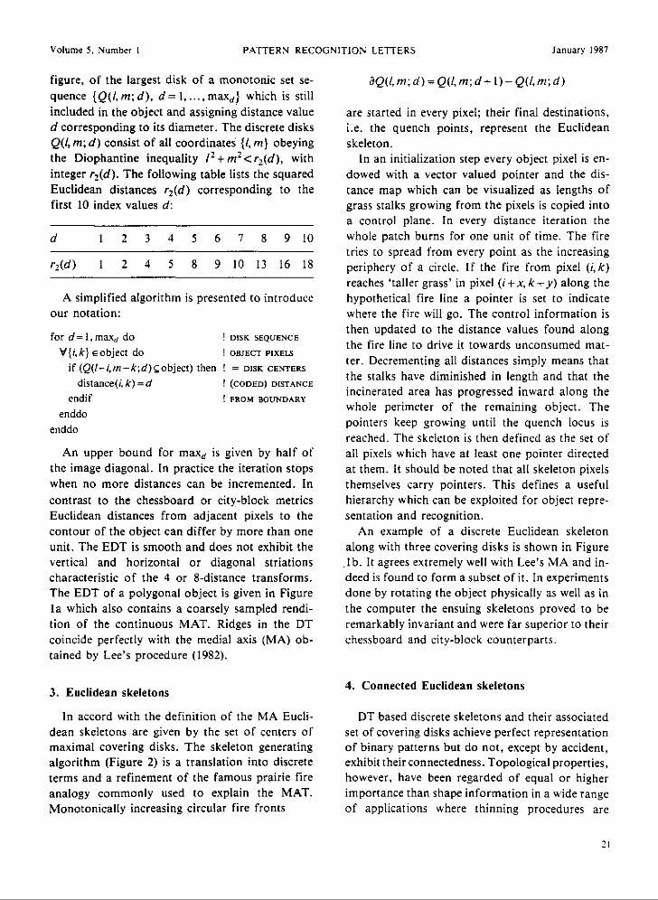
figure, of the largest disk of a monotonic set se-quence (Q(1, m; d), d = I, . . . , maid} which is stillincluded in the object and assigning distance valued corresponding to its diameter . The discrete disksQ(I, m ; d) consist of all coordinates {l, m} obeyingthe Diophantine inequality I 2 +m2 <r2(d), withinteger r2(d) . The following table lists the squaredEuclidean distances r2 (d) corresponding to thefirst 10 index values d :
A simplified algorithm is presented to introduceour notation :
for d=1,maxd do
! DISK SEQUENCE
V(i,k ) E object do
! OBJECT PIXELSif (Q(I-i,m-k ;d)Cobject) then ! = DISK CENTERS
distance(i, k) = d
! (CODED) DISTANCE
endif
! FROM BOUNDARYenddo
enddo
An upper bound for maxd is given by half ofthe image diagonal . In practice the iteration stopswhen no more distances can be incremented . Incontrast to the chessboard or city-block metricsEuclidean distances from adjacent pixels to thecontour of the object can differ by more than oneunit . The EDT is smooth and does not exhibit thevertical and horizontal or diagonal striationscharacteristic of the 4 or 8-distance transforms .The EDT of a polygonal object is given in FigureIII which also contains a coarsely sampled rendi-tion of the continuous MAT . Ridges in the DTcoincide perfectly with the medial axis (MA) ob-tained by Lee's procedure (1982) .
3 . Euclidean skeletons
In accord with the definition of the MA Eucli-dean skeletons are given by the set of centers ofmaximal covering disks . The skeleton generatingalgorithm (Figure 2) is a translation into discreteterms and a refinement of the famous prairie fireanalogy commonly used to explain the MAT .Monotonically increasing circular fire fronts
3Q(1, m ; d)=Q(1,m; d+ 1)-Q(l, m ; d )
are started in every pixel ; their final destinations,i .e. the quench points, represent the Euclideanskeleton .
In an initialization step every object pixel is en-dowed with a vector valued pointer and the dis-tance map which can be visualized as lengths ofgrass stalks growing from the pixels is copied intoa control plane . In every distance iteration thewhole patch burns for one unit of time . The firetries to spread from every point as the increasingperiphery of a circle . If the fire from pixel (i,k)reaches `taller grass' in pixel (i+ .r, k+y) along thehypothetical fire line a pointer is set to indicatewhere the fire will go . The control information isthen updated to the distance values found alongthe fire line to drive it towards unconsumed mat-ter. Decrementing all distances simply means thatthe stalks have diminished in length and that theincinerated area has progressed inward along thewhole perimeter of the remaining object. Thepointers keep growing until the quench locus isreached. The skeleton is then defined as the set ofall pixels which have at least one pointer directedat them. It should be noted that all skeleton pixelsthemselves carry pointers . This defines a usefulhierarchy which can be exploited for object repre-sentation and recognition .
An example of a discrete Euclidean skeletonalong with three covering disks is shown in Figure.Ib. It agrees extremely well with Lee's MA and in-deed is found to form a subset of it . In experimentsdone by rotating the object physically as well as inthe computer the ensuing skeletons proved to beremarkably invariant and were far superior to theirchessboard and city-block counterparts .
4. Connected Euclidean skeletons
DT based discrete skeletons and their associatedset of covering disks achieve perfect representationof binary patterns but do not, except by accident,exhibit their connectedness . Topological properties,however, have been regarded of equal or higherimportance than shape information in a wide rangeof applications where thinning procedures are
January 1987
d 1 2 3 4 5 6 7 8 9 10
r 2 (d) 1 2 4 5 8 9 10 13 16 18

Volume 5, Number I
PATTERN RECOGNITION LETTERS
January 1987
V(i,k}eobject do
! INITIALIZE :
pointer(i,k)={0,0}
! DESTINATION POINTERS
control(i,k)=distance(i,k) ! CONTROL INFORMATION
skeleton (I, k) = 0
! SKELETONenddo
for d=1,maxd do
! INCREASING DISTANCES
V {i, k} a object doV {l, m} a .Q(l, m ; d) do
! POINTS ON CIRCULAR FIRE
if (control (i,k)Sdistance(i+1,k+m) then
! FRONTS BURNT PREVIOUSLY?
pointer(i,k)={1,m}
! FIRE DESTINATION
control(i,k)=distance(i+I,,k+m)
! & PROPAGATIONendif
enddodistance(;k)=distance(i, k) - I
I CLIP BURNT PARTS
enddoenddo
V{i,k} eobject do
I FIRE FROM EACH POINT
{xy}=pointer(i,k)
I BURNS TO QUENCH LOCUS
skeleton(i+x,k+y)=l I MARK SKELETON
enddo
Figure 2 . Generation of hierarchically ordered Euclidean skeletons .
traditionally employed . The objectives of thinning(Rutovitz, 1966; Tamura, 1978 ; Pavlidis, 1980) areto reduce a plane object to a MA-like lineal set ofsingle pixel width, to maintain the connectivity ofobject and background, and to reflect shape infor-mation by preserving `end points' of objects . Thelast requirement in particular has led to a prolifera-tion of algorithms a critique of which was com-piled by Davies and Plummer (1981) . They arguethat `end points' are global features which cannotbe discriminated from `noise spurs' within thelocal 3*3 neighborhoods sufficient to establishconnectivity and, like Arcelli et al . (1981), theypropose to derive connected skeletons by linkinglocal maxima of previously calculated distancemaps .
Significantly improved descriptions of arbitraryobjects and their tips in particular cannot be ex-pected from this procedure as long as it is based onthe 4- or 8-neighbor DT's as was illustrated byHilditch (1983) in her comparison of parallel thin-ning algorithms . Indeed, 8- (or 4-)connectivity pre-serving thinning by successive deletion of contourpoints generates skeletons in a manner which
22
makes them, just like the local maxima, subsets ofthe ridge points in distance maps employing thechessboard (or city-block) metrics. This fact is ex-ploited by Arcelli and Sanniti di Baja (1985) to im-plement an effective width independent thinningalgorithm . Skeletons obtained by thinning or maxi-mum linking will thus simply trace out longer orshorter connected sections of the ridge-lines in therespective DT's . A conventional thinned skeletonusing 8-connectivity for the object is superimposedon its disjoint Euclidean counterpart in Figure Icand seen to deviate substantially from the con-tinuous MA in Figure la .
The superior shape representation achieved bydiscrete Euclidean skeletons is a compelling reasonfor devising procedures for establishing connected-ness by linking local maxima in the EDT in such away that the continuous MA is closely approxi-mated . The methods applied to n-neighborhoodDT's cannot be used immediately since they makeno provision for the fact that the Euclidean metricis incompatible with the metric induced by gener-ating connectedness with 3*3 window operators .Pixels with constant Euclidean distance need not

Volume 5, Number I
PATTERN RECOGNITION LETTERS
be adjacent in any n-neighborhood sense such thatindiscriminate successive erosion confuses the EDT .The topological properties of binary objects wouldbe represented faithfully but the resulting patternstend to have many spurious limbs sticking awayfrom the Euclidean ridges and differ considerablyfrom the continuous MA .
An approach which tries to reconcile the Eucli-dean metric and connectedness is given by the fol-lowing algorithm shown in Figure 3 .
V {i, k} E object docon_skeleton(1, k)=1
enddo
conversion into a graph representation can be ob-tained by at most two final thinning steps .
A connected Euclidean skeleton is shown inFigure Id and seen to give satisfactory agreementwith the continuous MA . The present algorithmstill does not suppress spurious limbs entirely as isapparent in the `nose' part of the skeleton . Morerefined methods are currently being investigatedwhich indicate that a new contour based algorithmwill yield better results .
5. Representation of extended objects
The EDT allows the definition of an objectrepresentation which puts structural details of abinary figure into a natural order of significance .The skeleton points have an inherent hierarchicalrelationship by means of which their geometricalvicinity can be expressed to complement and sim-
January 1987
The neighborhood code {nc(i,k)} is computedby convolving the object with a 3 .3 kernel suchthat the center-surround pixels are mapped into thecoefficients of an 8-bit number . Deletability of apixel is determined as operation LUT(nc) on alook-up-table which can accomodate any of thesituations proposed in the multitude of thinningalgorithms (Hilditch, 1983) and actual deletion iscarried out in the familiar North, South, East,West passes . Unit width to facilitate subsequent
INITIALIZE :
I CONNECTED SKELETON
for d=1, maid do
I REMOVE
V{i,k}econ-skeleton do
POINTS WITH
nc (i, k) =3 .3_neighborhood_code (i, k)enddoV {i, k} E {object I distance(i, k)? d } do N,S,E, W
if (LUT(nc(i, k)) ='delete'
I NO SIGNIFICANCE FOR
and skeleton(i,k)=0) then
I TOPOLOGY & GEOMETRY
con_skeleton(i, k) = 0endif
enddoenddo
Figure 3 . Correcting topology of discrete Euclidean skeletons .
plify proposals like the augmented MAT of Ahujaand Hoff (1984) which couples the skeletal pointswith their neighborhood graph .
This hierarchy originates from the pointer gener-ating procedure presented in Section 3 . The re-sulting data structure can be appreciated byinvestigating a synthetic figure produced fromoverlapping disks and consisting of two connectedcomponents as in Figure 4a . The isolated disk haspointers for all pixels which lead directly to thecenter. This defines a skeletal point of topmosthierarchical level since it immediately representsone object component . The directions of thepointers are indicated by 4 different shades of graywhile their length is given by the Euclidean dis-tance of each pixel to its skeletal point and sup-pressed in the figure . The component made fromoverlapping disks has a more involved skeletonstructure with different levels of hierarchy dis-
23

Volume 5, Number I
a
Figure 4 . Skeleton generating pointers and their hierarchy . (a) Euclidean skeleton (bright) and generating pointers for object of singleand overlapping circular areas . All object positions have pointers to centers of maximal covering disks . Pointer direction is indicatedby gray (left, down), dark (right, down), black (right, up) and light gray (left, up); (b) circular object components and hierarchy ofskeleton-pointers (correspondence identified by texture) . Isolated disk generates pointers of identical (top) level while components with(sufficient) overlap give tree-structure . Small circle in 9 o'clock position is severed because its center remains outside all maximal
covering disks of big component (see text) .
tinguished by the circle radii and their varyingdegrees of overlap .
In the case of a small disk center inside the peri-meter of a larger circle, both centers are of courseskeletal points as is the line connecting them, as isto be expected from the grass fire analogy . Thepointers at all skeleton loci are directed to thecenter of the larger disk so that the small pro-truding circle has a lower hierarchical level . In thedegenerate case of equal radii both centers have thesame level .
The second situation is represented by twocircles each of whose centers are outside the other'sperimeter. It must be subdivided into the casewhere the center of the smaller circle lies outside(inside) its reflexion in the secant through thepoints where the original perimeters intersect. Ifthe smaller disk is `inside' its skeletal points are in-corporated into the skeleton of the bigger one atlower hierarchical level . Otherwise the smaller diskis severed and considered an entity of its own attop level .
We assert that this capability of 'mitosis' en-hances the power of the hierarchical skeleton struc-ture since it can be used for automatic pruning of
24
PATTERN RECOGNITION LETTERS January 1987
noisy contours and it helps to identify separated orabutting objects which have become fused in theprocess of converting a gray level picture into abinary image. Different, nearly or completelydisconnected, object components generated by afamily of overlapping disks with a unique largestmember can eventually be identified by the toplevel entries in the hierarchical skeleton structure .More complicated figures can be decomposed intosuch substructures and be classified similarly and itwould be attractive to construct an augmentedMAT on this basis . An example of a hierarchicalskeleton is given in Figure 4b where the correspon-dence between level and disk is indicated bytexture .
6. Proximity of object components
A concept of proximity of objects is crucial foranalyzing and describing scenes which consist oflogically interrelated items or characteristic ar-rangements of picture primitives . A sound notionof neighborhood should reflect geometrical infor-mation and possess properties analogous to thoseof the well known topological concept of neighbor-

\oium_ 5 . Numher
PAFLERN RECOGNITION LETTERS
Januar !9R -
hood of a point .A suggestive definition of proximity in binary
images is based on propagating individual objectcomponents over the background until the in-fluence zones of several connected componentsbalance . Using the Euclidean metric for this pro-cess will produce an obvious generalization of theVoronoi tesselation where the boundaries of the in-fluence zones coincide with the exoskeleton . TheEDT can be augmented to solve the dual problemby endowing it with the capacity of passing infor-mation from an object component to its region ofinfluence . The resultant algorithm is presented inFigure 5 .
V{p,q}ebackgrounddo
! INITIALIZE :
pointer(p,q)={0,0}
! PROPAGATION POINTERS
enddo
V{i,k}Eobjeet do
! PREVENT PROPAGATION
pointer(t,k)={m,co
TO OBJECT INTERIOR
enddo
for d=I,max,e doV{i,k}eobject do
V {/, m} e aQ(I, m; d) do
! PROPAGATE OBJECT
if (pointer(i+l,k+m)={0,0} then ! OVER BACKGROUND
pointer(i+(,k+m)={-l.-m}
! DESTINATION
endifenddo
enddoenddo
V ;p,q}E background do
! PROPAGATE
{x. y}=pointer(p,q)
! LABEL
FROM
label(p,q)=original_label(p+x,q+y)
! OBJECT TO
enddo
BACKGROUND
Figure 5 . Creating regions of influence by expansion of object components .
Euclidean zones of influence around simply con-nected object components is given in Figure 6 . Theframe boundary is treated as one special objectcomponent to display the clearance of peripheralpoints .
Region boundaries are formed by the crack be-tween pixels with different attributes . These com-prise the property of belonging to object or
The stratagem consists of introducing the Eucli-dean vector-distance between each point of thebackground and its nearest object pixel . The dis-tance iteration is performed such that only peri-pheral object pixels are taken into account andstops when all pointers have nonvanishing length .Any desirable object information such as identityof a component or previously computed shape fea-tures can be incorporated into a label which istransmitted into the neighborhood by simple vec-tor propagation .
Zones of influence are recognized as regions ofhomogeneous labels which surround the 'seed'-component and also fill its holes . An example of
background, component labels, distance valuesand task specific ancillary information . Everyboundary locus is accordingly associated with apair of attribute sets which reflect the relativespatial arrangement of object components .
A natural extension to the augmented EDT is tocompile the crack boundaries from a raster arrayinto list encoded line structures just as connected

Volume ` . `umber I
Figure 6. Augmented distance transform and region labels .Euclidean expansion of (labeled) object components creates'regions of influence' indicated by different gray values . Image
border is regarded as special object component .
skeletons are converted into a graph representa-tion . The attributes are carried along and alsoentered in the data structure . The symbolic repre-sentation of objects and their proximity are a pre-requisite to analyze more complex scenes and willbe used to interpret drawn documents .
7. Identification of abutting objects
A common requirement in industrial applica-tions of computer vision is that of recognition andidentifying physical objects from their images, fortasks ranging from simple sorting and packagingto complicated robot assembly . The silhouettes ofisolated objects in many cases contain sufficient in-formation to derive discriminatory shape featuressuch as parameter values of a priori known analyti-cal models, Fourier descriptors of the contour orsets of moments . To analyze a scene containingmany objects on the basis of a binary image thenamounts to dissecting the overall silhouette into itsconstituent parts, or attributing appropriate por-tions of the visible contour to the correct gener-ating object .
The extremes of arbitrarily overlapping partsand totally isolated objects are often used to illus-
26
PATTERN RECOGNITION LETTER January !9i'
trace the problems and the potential of under-standing binary images of industrial scenes . Weargue that a more realistic scenario for actualapplications is given by an intermediate situationwhere objects touch but do not lie on top of oneanother. Bilevel images of parts on conveyor beltsor similar, essentially two-dimensional, supplydevices will then consist of touching shapes whichcan be separated with the aid of hierarchical Eucli-dean skeletons .
We illustrate the deagglomeration of abuttingobjects with a simple example where the shape fea-tures of the constituent figures are parameters ofan analytical model . In a chocolate factory, ovalpieces of candy are put on trays for cooling beforebeing packaged . The task is to find their center co-ordinates and orientation to drive a suction devicefor pickup and manipulation .
Binary images can be obtained by trans'illumina-tion . One particular configuration is given by thedark blobs in Figures 7a, 7b, 7c and seen to formone single connected component . The original ar-rangement is viewed from above in Figure 7d .Contours are immediately available and sufficientto determine center, orientation and axis-of-fit-ellipses provided the segmentation of the indi-vidual pieces has been established successfully . Thetotal silhouette is dissected into appropriate partsby using the pointers which produce the skeletonfrom the EDT . Each elliptical blob can be decom-posed into one biggest covering disk and a descen-ding hierarchy of smaller disks just as in theexample of Figure 4 . All object pixels have asso-ciated skeleton pointers which ultimately lead toone specific top level disk . Points of the visiblecontour in particular are thus automatically assign-ed to their specific oval piece of candy as indicatedin Figure 7e . A least squares fit produces the resultof Figure 7f which shows the ellipses and the orien-tation of their major axes superimposed on the setof contour pixels . Scrutiny of the numerical valuesreveals that the chocolate-makers turned out uni-form pieces of less than one percent variation insize .
The potential of the hierarchical Euclideanskeleton is not fully demonstrated by the chosentutorial example since agglomerations of objectswith highly diverse shapes and sizes can be treated

Volume 4, Number I
Figure 7 . Deagglomeration of abutting elliptical objects- (a,b,c) distance transforms (gray intensities) and skeletons (bright) of binaryelliptical objects using 4metric (a), Euclidean distance (b) and 8-metric (c) ; (d) original pieces of candy ; (e) skeleton pointers (directioncode as in Figure 2) and Euclidean skeleton . Object borders are relayed to largest covering disk by pointer hierarchy ; IfI object contours
(black), periphery and direction of major axes of fit ellipses (light) identifying constituents .
by the same approach . The EDT is superior to the4- or 8-neighbor DT's not only due to the naturalhierarchy of its skeleton but also because of itsaccuracy as can be inferred by comparing Figures7a, 7b and 7c . The EDT main ridges directly dis-play the orientation of the ellipses while both otherDT's show ridges whose orientation is more domi-nated by the metric than the object . The computa-tional complexity of EDT and hierarchicalskeleton generation appears well compensated bythe results as compared to those obtained by thechessboard or city-block DT's . In addition, a se-quential algorithm is currently under test whichwill reduce computation times considerably whileretaining full accuracy .
8. Automated interpretation of drawings
The automated analysis and interpretation of
PArTERN RECOGNITION LETTERS January 194'
engineering drawings or documents with line struc-tures in general represents an area of computervision which may be regarded as prototypical formodel guided image understanding . Specimens ofthis kind divide into object and complementalbackground in a natural way and can be segmentedby existing image processing methods . The objectcomponents and their spatial arrangement have tobe extracted and represented symbolically . Theyfurnish the geometrical and topological context forinterpretation with a task specific model . Its con-struction is essentially based on the rules whichhave to be obeyed when generating the document,
Standard procedures to recognize symbols inline drawings are chiefly based on the detection ofsubgraph isomorphisms in graphical representa-tions of thinned images . Line patterns consistingof elements with varying width and length incharacteristic spatial arrangements impede analysissince geometric relationships of components are
not represented in standard image graphs .The connected skeleton and the boundaries of
the dual influence regions with their attributes arewell suited to express the characteristic spatial ar-rangements in line patterns and to recognize themas logical entities . The connected thinned skeletonyields the primitives point, line, and junction-nodes with structure
point :={point_no, x, v, radius},line :={line-no, startpoint, endpoint},node
node-no, point-no, line-no,next-line-no ; ,
while the boundaries of the influence regions pro-duce the attributed dual primitives
d_point := {d_point_no, x, y, radius},d_line :_ td-line-no, d_startpoint,
d_endpoint, left_component,right-component } ,
d_node := ;d_node_no, d_point_no,d_line_no, next _d_Iine_no},
which are compiled in a relational data structure .All primitives carry an identification number . Geo-metric information is specified by the coordinatesand radius of a point or by references to the startand end elements of a previously ordered sequenceof points forming a line . The nodes are specialpoints which have to contain references to the 3 or4 lines forming the junction . This is done by givinga pair whose members follow one another in a fix-ed sense of revolution . The attributes are sym-metric for the direct and dual primitives except forthe dual line which contains references to theobject components closest to its left and right`banks' .The primitives extracted from the connectivity
preserving augmented EDT of object and back-ground can be exploited to recognize specific linepatterns in quite an obvious manner . Parallel linesas used to represent main roads in maps would becharacterized by an enclosed dual line whosepoints have constant radius . A dashed line in anengineering drawing can be reconstructed from thesingle strokes by observing their geometric prox-imity which shows up in the respective distancesalong the separating dual line . These loose ideashate been formulated systematically using tools of
PATTERN RECOGNITION LEtTERS Januar' 198-
artificial intelligence to build the model. A contextfree attributed grammar is used in which the ter-minal elements are identical to the extracted primi-tives . Five different line types present in theschematic of a control circuit and the familiar car-tographic symbols in maps were instantiatedsucessfully by the model . A full account is outsidethe scope of this paper and has been presented else-where (Egeli et al ., 1985) .
9. Conclusions
The EDT gives a MAT-like robust object des-cription which is almost invariant under rotationsand permits exact reconstruction . The Euclideanskeleton encodes shape properties of a binaryfigure in a natural hierarchy by means of which itbecomes possible to identify objects in mutual con-tact automatically from the overall silhouette .Metric properties and object connectedness can bereconciled by linking the local maxima of the in-itial Euclidean skeleton into a topology preservingredundant structure which is particularly suited forcompilation into a graph representation . Theproximity of object components can be extractedfrom the augmented EDT of the background andexpressed by attributes associated with the pointsof a generalized Voronoi diagram. The primitivesextracted from the direct and dual EDT's are im-mediately suited as terminal elements of an attri-buted grammar to describe characteristic generalpatterns of lineal elements in engineering sche-matics and road maps. The EDT and its ramifica-tions can be regarded as forming a sound basis forthe structural interpretation of binary images .
References
Ahuja, N. and W. Hoff 11984) . Augmented medial axis trans-form . Proc 7th Int . Conf. Pattern Recognition, Montreal,Canada . (1) 336-338 .
Arcelli, C ., L .P . Cordella and S . Le'ialdi (1981) . From localmaxima to connected skeleton . IEEE Trans . Putt . Anal .Mach . Intel!. 4, 134-143 .
Arcelli, C . and G . Sanniti di Baja (!985) . A width-independentfat thinning algorithm . IEEE Trans. Pall . Anal. Mach.Iatell. 7, 463-a"4 .

Volume 5 . Number I
PATTERN RECOGNITION LETTERS
January 1987
Danielsson, P .-E . (1980) . Euclidean distance mapping . Com-put. Graph . Image Processing 14, 227-248 .
Davies, E .R. and A .P.N. Plummer (1981) . Thinning algor-ithms: A critique and a new methodology . Pattern Recogni-tion 14, 53-63 .
Egeli, E ., F . Klein and G . Maderlechner (1985), ModellgestutzteSymbolinstanziierung aus relational verknupften Bifdprimi-tiven . Mustererkennung 1985, 7 . DAGM-Symposium, Er-langen, Germany, Springer 267-271 .
Hilditch, CJ . (1983) . Comparison of thinning algorithms on aparallel processor . Image Vision Computing 1 . 115-132 .
Lee, D .T . (1982) . Medial axis transformation of a planar shape .IEEE Trans. Part . Anal. Mach . Intell . 4, 363-369.
Pavlidis, T . (1980) . A thinning algorithm for discrete binary im-ages . Comput. Graph. Image Processing 13, 142-I57 .
Pavlidis, T . (1982) . An asynchronous thinning algorithm . Com-put. Graph . Image Processing 20, 133-157 .
Rutovitz, D . (1966) . Pattern recognition . J. R. Statist . Soc . 129,504-530.
Tamura, H. (1978) . A comparison of line thinning algorithmsfrom digital geometry viewpoint . Proc. 4th Int. Joint Conf.Pattern Recognition, Kvoto, Japan, 715-719 .
Toriwaki, J . and S . Yokoi (1981) . Distance transformationsand skeletons of digitized pictures with applications . In : L .N .Kanal and A . Rosenfeld, Eds ., Progress in Pattern Recogni-tion . North-Holland, Amsterdam, 187-264 .
29