etsi/tc/smg#30 td smg 584/99 brighton, u.k. … available smg only 28 ts 101 350 v8.0.0 (1999-07)...
TRANSCRIPT

ETSI/TC/SMG#30 TD SMG 584/99Brighton, U.K. Agenda Item: 6.29 - 11 November 1999
Source: SMG2
CRs to GSM 03.30 and GSM 03.64 (EDGE)
Introduction :
This document contains 4 CRs to GSM 03 Series (all strategic) agreed by SMG2and forwarded to SMG for approval.
TdocSMG2
SPEC CR REV PHASE VERS SUBJECT CAT Page
2-99-A72 03.30 A006 R99 8.0.0 850 Link Budgets B 22-99-992 03.64 A058 R99 8.0.0 EGPRS fine tuning B 62-99-D99 03.64 A059 1 R99 8.0.0 EDGE Compact Cell Reselection B 172-99-D96 03.64 A060 1 R99 8.0.0 EDGE Compact logical channels B 20

ETSI STC SMG2 Tdoc SMG2 992/99
Meeting no 32 Agenda item 7.2.6.6Bordeaux, France20 - 24 September 1999
ETSI SMG2 Working Session on EDGE Tdoc SMG2 EDGE 2E99-390Montigny Le Bretonneux, France Agenda Item 6.424th-27th August, 1999Source: SMG2EDGE WS #101 Revised from Tdoc 2E99-283
CHANGE REQUEST No : A058 Please see embedded help file at the bottom of thispage for instructions on how to fill in this form correctly.
Technical Specification GSM / UMTS: 03.64 Version 8.0.0
Submitted to SMG 30 for approval X without presentation ("non-strategic")list plenary meeting or STC here ↑ for information with presentation ("strategic") X
PT SMG CR cover form. Filename: crf26_3.doc
Proposed change affects: SIM ME X Network X(at least one should be marked with an X)
Work item: EDGE Compact and support for EGPRS in ANSI-136 networks
Source: SMG2 Date: 9.11.1999
Subject: EGPRS fine tuning
Category: F Correction Release: Phase 2A Corresponds to a correction in an earlier release Release 96
(one category B Addition of feature X Release 97and one release C Functional modification of feature Release 98only shall be D Editorial modification Release 99 Xmarked with an X) UMTS
Reason forchange:
Latest fine tuning of EGPRS coding
Clauses affected: 6.5.4; 6.5.5; 6.5.5.1.2.
Other specs Other releases of same spec → List of CRs:affected: Other core specifications → List of CRs:
MS test specifications / TBRs → List of CRs:BSS test specifications → List of CRs:O&M specifications → List of CRs:
1 SMG2EDGE WS #10: Alcatel, Allgon, AT&T Wireless, Bouygues Telecom, Comsys, CSELT, DSP Inc, Ericsson, France Telecom,Hewlett Packard, Interdigital Communications, Lucent Technologies, Motorola, Nokia, Nortel Networks, Orange, Rhode & Schwarz,Roke Manor, SBC, Sharp, Siemens, Vodafone

Othercomments:
ETSI
TS 101 350 V8.0.0 (1999-07)21Available SMG only
6.5.4 Radio Block Structure
Different Radio Block structures for data transfer and control message transfer purposes are defined. The Radio Blockstructure for data transfer is different for GPRS and EGPRS, whereas the same Radio Block structure is used for controlmessages. For detailed definition of radio block structure, see GSM 04.60.
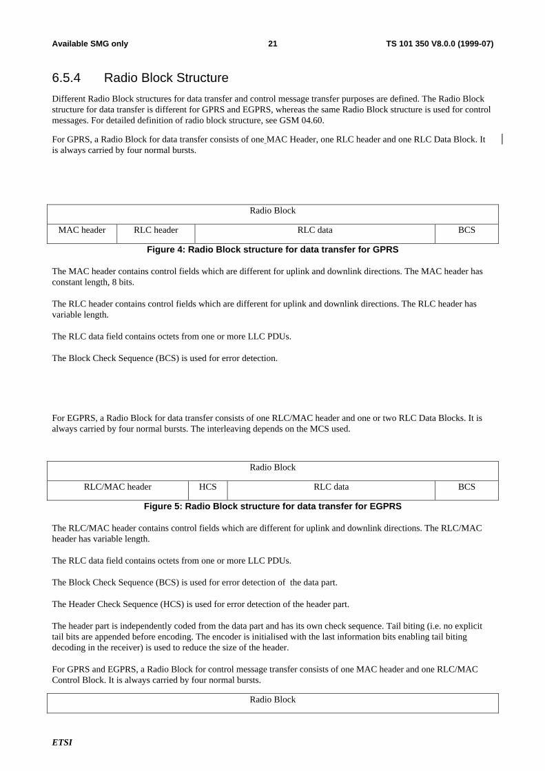
For GPRS, a Radio Block for data transfer consists of one MAC Header, one RLC header and one RLC Data Block. Itis always carried by four normal bursts.
Radio Block
MAC header RLC header RLC data BCS
Figure 4: Radio Block structure for data transfer for GPRS
The MAC header contains control fields which are different for uplink and downlink directions. The MAC header hasconstant length, 8 bits.
The RLC header contains control fields which are different for uplink and downlink directions. The RLC header hasvariable length.
The RLC data field contains octets from one or more LLC PDUs.
The Block Check Sequence (BCS) is used for error detection.
For EGPRS, a Radio Block for data transfer consists of one RLC/MAC header and one or two RLC Data Blocks. It isalways carried by four normal bursts. The interleaving depends on the MCS used.
Radio Block
RLC/MAC header HCS RLC data BCS
Figure 5: Radio Block structure for data transfer for EGPRS
The RLC/MAC header contains control fields which are different for uplink and downlink directions. The RLC/MACheader has variable length.
The RLC data field contains octets from one or more LLC PDUs.
The Block Check Sequence (BCS) is used for error detection of the data part.
The Header Check Sequence (HCS) is used for error detection of the header part.
The header part is independently coded from the data part and has its own check sequence. Tail biting (i.e. no explicittail bits are appended before encoding. The encoder is initialised with the last information bits enabling tail bitingdecoding in the receiver) is used to reduce the size of the header.
For GPRS and EGPRS, a Radio Block for control message transfer consists of one MAC header and one RLC/MACControl Block. It is always carried by four normal bursts.
Radio Block

ETSI
TS 101 350 V8.0.0 (1999-07)22Available SMG only
MAC header RLC/MAC Control Message BCS
Figure 6: Radio Block structure for control message for GPRS and EGPRS
The MAC header contains control fields which are different for uplink and downlink directions. The MAC header hasconstant length, 8 bits.
The Block Check Sequence (BCS) is used for error detection.
The RLC/MAC Control message field contains one RLC/MAC control message.
MAC header contains control fields which are different for uplink and downlink directions. MAC header is constantlength, 8 bits.
RLC header contains control fields which are different for uplink and downlink directions. RLC header is variablelength.
RLC data field contains octets from one or more LLC PDUs.
Block Check Sequence (BCS) is used for error detection.
RLC/MAC Control message field contains one RLC/MAC control message.
6.5.5 Channel Coding
NOTE: The text in this subclause is informative. The normative text is in GSM 05.03 [5]. Where there is aconflict between these descriptions, the normative text has precedence.
Four coding schemes, CS-1 to CS-4, are defined for the GPRS packet data traffic channels. For all other GPRS packetcontrol channels than Packet Random Access Channel (PRACH) and Packet Timing Advance Control Channel onUplink (PTCCH/U), coding scheme CS-1 is always used. For access bursts on PRACH, two coding schemes arespecified.
All coding schemes (CS-1 to CS-4) are mandatory for MSs supporting GPRS. CS-1 is mandatory for a networksupporting GPRS.
Nine modulation and coding schemes, MCS-1 to MCS-9, are defined for the EGPRS packet data traffic channels. For allEGPRS packet control channels the corresponding GPRS control channel coding is used. Coding schemes MCS-1 toMCS-9 are mandatory for MSs supporting EGPRS. A network supporting EGPRS may only support only some of theMCSs.

ETSI
TS 101 350 V8.0.0 (1999-07)24Available SMG only
6.5.5.1.2 Channel coding for EGPRS PDTCH
Nine different modulation and coding schemes, MCS-1 to MCS-9, are defined for the EGPRS Radio Blocks (4 bursts,20ms) carrying RLC data blocks. The block structures of the coding schemes are shown from Figure 10 to Figure 18 andin Table 4. A general description of the MCSs is given in Figure 9.
The MCSs are divided into different families A, B and C. Each family has a different basic unit of payload: 37 (and 34),28 and 22 octets respectively. Different code rates within a family are achieved by transmitting a different number ofpayload units within one Radio Block. For families A and B, 1, 2 or 4 payload units are transmitted, for family C, only 1or 2 payload units are transmitted.
When 4 payload units are transmitted (MCS-7, MCS-8 and MCS-9), these are splitted into two separate RLC blocks (i.e.with separate sequence numbers and BCSs). These blocks in turn are interleaved over two bursts only, for MCS-8 andMCS-9. For MCS-7, these blocks are interleaved over four bursts. All the other MCSs carry one RLC block which isinterleaved over four bursts. When switching to MCS-3 or MCS-6 from MCS-8, 3 or 6 padding octets, respectively, areadded to the data octets.
37 octets 37 octets 37 octets37 octets
MCS-3
MCS-6
Family A
MCS-9
28 octets 28 octets 28 octets28 octets
MCS-2
MCS-5
MCS-7
Family B
22 octets22 octets
MCS-1
MCS-4
Family C
34+3 octets34+3 octets
MCS-3
MCS-6Family A padding
MCS-8
34 octets 34 octets 34 octets34 octets
Figure 9: General description of the Modulation and Coding Schemes for EGPRS
To ensure strong header protection, the header part of the Radio Block is independently coded from the data part of theRadio Block (8 bit CRC calculated over the header -excl. USF- for error detection, followed by rate 1/3 convolutionalcoding –and eventually puncturing- for error correction). Three different header formats are used, one for MCS-7,MCS-8 and MCS-9, one for MCS-5 and MCS-6 and one for MCS-1 to MCS-4. The two first formats are for 8PSK
ETSI
TS 101 350 V8.0.0 (1999-07)25Available SMG only
modes, the difference being in the number of Sequence Numbers carried (2 for MCS-7, -8 and -9, 1 for MCS-5 and –6).The third format is common to all GMSK modes. The header is always interleaved over four bursts. See GSM 04.60 formore details.

ETSI
TS 101 350 V8.0.0 (1999-07)26Available SMG only
Following figures show the coding and puncturing for all the Modulation and Coding Schemes, for downlink traffic.
Figure 10: Coding and puncturing for MCS-9; uncoded 8PSK, two RLC blocks per 20ms
Figure 11: Coding and puncturing for MCS-8; rate 0.92 8PSK, two RLC blocks per 20ms
P2 P3P1 P2
puncturingpuncturing
1836 bits
USF RLC/MACHdr.
36 bits
Rate 1/3 convolutional coding
135 bits
612 bits
612 bits124 bits36 bitsSB = 8
1392 bits
45 bits
Data = 592 bits BCS TB
612 bits
612 bits 612 bits
1836 bits
Rate 1/3 convolutional coding
EFBIData = 592 bits BCS TBEFBI
612 bits 612 bits 612 bits
P3 P1
3 bits
HCS
puncturing
P2 P3P1 P2
puncturingpuncturing
1692 bits
USF RLC/MACHdr.
36 bits
Rate 1/3 convolutional coding
135 bits
564 bits
612 bits124 bits36 bitsSB = 8
1392 bits
45 bits
Data = 544 bits BCS TB
564 bits
612 bits 612 bits
1692 bits
Rate 1/3 convolutional coding
EFBIData = 544 bits BCS TBEFBI
612 bits 612 bits 612 bits
P3 P1
3 bits
HCS
puncturing

ETSI
TS 101 350 V8.0.0 (1999-07)27Available SMG only
Figure 12: Coding and puncturing for MCS-7; rate 0.76 8PSK, two RLC blocks per 20ms
P2 P3P1 P2
puncturingpuncturing
1404 bits
USF RLC/MACHdr.
36 bits
Rate 1/3 convolutional coding
135 bits
468 bits
612 bits124 bits36 bitsSB = 8
1392 bits
45 bits
Data = 448 bits BCS TB
468 bits
612 bits 612 bits
1404 bits
Rate 1/3 convolutional coding
EFBIData = 448 bits BCS TBEFBI
612 bits 612 bits 612 bits
P3 P1
3 bits
HCS
puncturing

ETSI
TS 101 350 V8.0.0 (1999-07)28Available SMG only
Figure 13: Coding and puncturing for MCS-6; rate 0.49 8PSK, one RLC block per 20 ms
Figure 14: Coding and puncturing for MCS-5; rate 0.37 8PSK, one RLC block per 20 ms
P2P1puncturing
1836 bits
USF RLC/MACHdr.
Data = 74 octets = 592 bits BCS
36 bits
Rate 1/3 convolutional coding
99 bits
612 bits
1248 bits100 bits36 bitsSB = 8
1392 bits
33 bits
TBFBI EHCS
3 bits
1248 bits
+1 bit
P2P1puncturing
1404 bits
USF RLC/MACHdr.
Data = 56 octets = 448 bits BCS
36 bits
Rate 1/3 convolutional coding
99 bits
468 bits
1248 bits100 bits36 bitsSB = 8
1392 bits
33 bits
TBFBI EHCS
3 bits
1248 bits
+1 bit

ETSI
TS 101 350 V8.0.0 (1999-07)29Available SMG only
Figure 15: Coding and puncturing for MCS-4; uncoded GMSK, one RLC block per 20 ms
Figure 16: Coding and puncturing for MCS-3; rate 0.80 GMSK, one RLC block per 20 ms
P1 P3P2
puncturing
1116 bits
USF RLC/MACHdr.
Data = 44 octets = 352 bits BCS
12 bits
Rate 1/3 convolutional coding
108 bits
372 bits
372 bits68 bits12 bitsSB = 12
464 bits
36 bits
TBFBI EHCS
3 bits
372 bits 372 bits
puncturing
P1 P3P2
puncturing
948 bits
USF RLC/MACHdr.
Data = 37 octets = 296 bits BCS
12 bits
Rate 1/3 convolutional coding
108 bits
316 bits
372 bits68 bits12 bitsSB = 12
464 bits
36 bits
TBFBI EHCS
3 bits
372 bits 372 bits
puncturing

ETSI
TS 101 350 V8.0.0 (1999-07)30Available SMG only
Figure 17: Coding and puncturing for MCS-2; rate 0.66 GMSK, one RLC block per 20 ms
Figure 18: Coding and puncturing for MCS-1; rate 0.53 GMSK, one RLC block per 20 ms
P1 P2
puncturing
672 bits
USF RLC/MACHdr.
Data = 28 octets = 224 bits TB
12 bits
Rate 1/3 convolutional coding
108 bits
244 bits
372 bits68 bits12 bitsSB = 12
464 bits
36 bits
BCS
puncturing
HCS FBI E
3 bits
372 bits
P1 P2
puncturing
588 bits
USF RLC/MACHdr.
Data = 22 octets = 176 bits TB
12 bits
Rate 1/3 convolutional coding
108 bits
196 bits
372 bits68 bits12 bitsSB = 12
464 bits
36 bits
BCS
puncturing
HCS FBI E
3 bits
372 bits

ETSI
TS 101 350 V8.0.0 (1999-07)31Available SMG only
The USF has 8 states, which are represented by a binary 3 bit field in the MAC Header. The USF is encoded to 12symbols similarily to GPRS, (i.e., 12 bits for GMSK modes and 36 bits for 8PSK modes).
The FBI (Final Block Indicator) bit and the E (Extension) bit defined in GSM 04.60 do not require extra protection:they are encoded along with the data part.
The first step of the coding procedure is to add a Block Check Sequence (BCS) for error detection.
The second step consists of adding six tail bits (TB) and a 1/3 rate convolutional coding for error correction that ispunctured to give the desired coding rate. The Pi for each MCS correspond to different puncturing schemes achievingthe same coding rate. The bits indicating the MCS used are in the coded header. In 8PSK mode the stealing bits (SB) ofthe block are used to indicate the two possible header formats. For GMSK eight stealing bits indicate CS-4.In both8PSK and GMSK modes the stealing bits (SB) of the block are used to indicate the header formats. There are eight SBfor 8PSK mode which allow to indicate four header formats. There are twelve SB for GMSK mode which allow toindicate two header formats: the first eight of the twelve SB indicate CS-4.
The details of the EGPRS coding schemes are shown in table 4:
Table 4: Coding parameters for the EGPRS coding schemes
Scheme Code rate HeaderCode rate
Modulation RLC blocksper Radio
Block(20ms)
Raw Datawithin one
RadioBlock
Family BCS Tailpayload
HCS Data ratekb/s
MCS-9 1.0 0.3536 2 2x592 A 59.2
MCS-8 0.92 0.3536 2 2x544 A 54.4
MCS-7 0.76 0.3536 2 2x448 B
2x12 2x6
44.8
MCS-6 0.49 1/3 1 592544+48
A 29.627.2
MCS-5 0.37 1/3
8PSK
1 448 B 22.4
MCS-4 1.0 0.5153 1 352 C 17.6
MCS-3 0.80 0.5153 1 296 272+24
A 14.813.6
MCS-2 0.66 0.5153 1 224 B 11.2
MCS-1 0.53 0.5153
GMSK
1 176 C
12 6
8
8.8
NOTE: the italic captions indicate the padding.

ETSI
ETSI STC SMG2Meeting no 32 Tdoc 1072/99Bordeaux, France Agenda item 7.2.6.620-24 September, 1999
CHANGE REQUEST No : A006 Please see embedded help file at the bottom of thispage for instructions on how to fill in this form correctly.
Technical Specification GSM / UMTS: 03.30 Version: 8.0.0
Submitted to SMG 30 for approval X Without presentation ("non-strategic")List SMG plenary meeting no. here ↑ for information with presentation ("strategic") X
PT SMG CR cover form. Filename: crf26_3.doc
Proposed change affects: SIM ME Network X(at least one should be marked with an X)
Work item: EDGE Compact and support for EGPRS in ANSI-136 networks
Source: SMG2 Date: Nov. 09, 1999
Subject: 850 Link Budgets
Category: F Correction Release: Phase 2A Corresponds to a correction in an earlier release Release 96
(one category B Addition of feature X Release 97And one release C Functional modification of feature Release 98Only shall be D Editorial modification Release 99 XMarked with an X) UMTS
Reason forchange:
Include 850 band information
Clauses affected: 3, 4
Other specs Other releases of same spec → List of CRs:Affected: Other core specifications → List of CRs:
MS test specifications / TBRs → List of CRs:BSS test specifications → List of CRs:O&M specifications → List of CRs:
Othercomments:
help.doc
<--------- double-click here for help and instructions on how to create a CR.

ETSI
Error! No text of specified style in document.2Error! No text of specified style in document.
3.3 RF-budgetsThe RF-link between a Base Transceiver Station (BTS) and a Mobile Station (MS) including handheld is best describedby an RF-budget. Annex A consists of 4 such budgets; A.1 for GSM 900 MS class 4; A.2 for GSM 900 MS class 2, A.3for DCS 1800 MS classes 1 and 2, aA.4 for GSM 900 class 4 in small cells, and A.5 for GSM 400 class 4 in small cells.GSM 900 RF-budgets should be used for 850 band.
The antenna gain for the hand portable unit can be set to 0 dBi due to loss in the human body as described in CCIRReport 567. An explicit body loss factor is incorporated in annex A.3
At 900 MHz, the indoor loss is the field strength decrease when moving into a house on the bottom floor on 1.5 mheight from the street. The indoor loss near windows ( < 1 m) is typically 12 dB. However, the building loss has beenmeasured by the Finnish PTT to vary between 37 dB and -8 dB with an average of 18 dB taken over all floors andbuildings (Kajamaa, 1985). See also CCIR Report 567.
At 1800 MHz, the indoor loss for large concrete buildings was reported in COST 231 TD(90)117 and values in therange 12 - 17 dB were measured. Since these buildings are typical of urban areas a value of 15 dB is assumed inannex A.3. In rural areas the buildings tend to be smaller and a 10 dB indoor loss is assumed.
The isotropic power is defined as the RMS value at the terminal of an antenna with 0 dBi gain. A quarter-wavemonopole mounted on a suitable earth-plane (car roof) without losses has antenna gain 2 dBi. An isotropic power of-113 dBm corresponds to a field strength of 23.5 dBuV/m for 925 MHz and 29.3 dBuV/m at 1795 MHz, see CEPTRecommendation T/R 25-03 and GSM 05.05 section 5 for formulas. GSM900 BTS can be connected to the samefeeders and antennas as analog 900 MHz BTS by diplexers with less than 0.5 dB loss.
3.4 Cell ranges
3.4.1 Large cells
In large cells the base station antenna is installed above the maximum height of the surrounding roof tops; the path lossis determined mainly by diffraction and scattering at roof tops in the vicinity of the mobile i.e. the main rays propagateabove the roof tops; the cell radius is minimally 1 km and normally exceeds 3 km. Hata's model and its extension up to2000 MHz (COST 231-Hata model) can be used to calculate the path loss in such cells (see COST 231 TD (90) 119Rev 2 and annex B).
The field strength on 1.5 m reference height outdoor for MS including handheld is a value which inserted in the curvesof CCIR Report 567-3 Figure 2 (Okumura) together with the BTS antenna height and effective radiated power (ERP)yields the range and re-use distance for urban areas (section 5.2).
The cell range can also be calculated by putting the maximum allowed path loss between isotropic antennas into theFigures 1 to 3 of annex C. The same path loss can be found in the RF-budgets in annex A. The figures 1 and 2(GSM 900) in annex C are based on Hata's propagation model which fits Okumura's experimental curves up to 1500MHz and figure 3 (DCS 1800) is based on COST 231-Hata model according to COST 231 TD (90) 119 Rev 2. GSM900 models should be used for 850 band range calculation.
The example RF-budget shown in annex A.1 for a GSM900 MS handheld output power 2 W yields about double therange outdoors compared with indoors. This means that if the cells are dimensioned for handhelds with indoor loss 10dB, the outdoor coverage for MS will be interference limited, see section 4.2. Still more extreme coverage can be foundover open flat land of 12 km as compared with 3 km in urban areas outdoor to the same cell site.
For GSM 900 the Max EIRP of 50 W matches MS class 2 of max peak output power 8 W, see annex A.2.
An example RF budget for DCS 1800 is shown in annex A.3. Range predictions are given for 1 W and 250 mW DCS1800 MS with BTS powers which balance the up- and down- links.
The propagation assumptions used in annex A1, A2, A3 are shown in the tables below :
For GSM 900 :

ETSI
Error! No text of specified style in document.3Error! No text of specified style in document.
Rural Rural Urban
(Open Area) (Quasi-open)
Base station 100 100 50
height (m)
Mobile height (m) 1.5 1.5 1.5
Hata's loss 90.7+31.8log(d) 95.7+31.8log(d) 123.3+33.7log(d)
formula (d in km)
Indoor Loss (dB) 10 10 15
For DCS 1800 :
Rural Rural Urban (*)
(Open Area) (Quasi-Open)
Base station 60 60 50
height (m)
Mobile height (m) 1.5 1.5 1.5
COST 231 100.1+33.3log(d) 105.1+33.3log(d) 133.2+33.8log (d)
Hata's loss
formula (d in km)
Indoor Loss (dB) 10 10 15
(*) medium sized city and suburban centres (see COST 231 TD (90) 119 Rev2). For metropolitan centres add 3dB to the path loss.
NOTE 1: The rural (Open Area) model is useful for desert areas and the rural (Quasi-Open) for countryside.NOTE 2: The correction factors for Quasi-open and Open areas are applicable in the frequency range 100-2000
MHz (Okumura,1968)

Error! No text of specified style in document.4Error! No text of specified style in document.
4.8 Channel allocationChannel allocation is normally made on an FDMA basis. However, in synchronized networks channel allocation can bemade on a TDMA basis. Note that a BCCH RF channel must always be fully allocated to one cell. In case of EGPRSCompact, CPBCCH must be allocated to one cell.
Channel allocation for uniform traffic distribution preferably follows one of the well known re-use clusters depending onC/I-distribution, e.g. a 9-cell cluster (3-cell 3-site repeat pattern) using 9 RF channel groups or cell allocations (CAs),(Stjernvall, 1985).
Channel allocation for non-uniform traffic distribution preferably follows a vortex from a BTS concentration on thetraffic centre, if a bell-shaped area traffic model holds. In real life the traffic distribution is more complicated with alsoline and point traffic. In this case the cell areas will be rather different for various BTS locations from city centre. Thechannel allocation can be optimized by using graph colouring heuristics as described in CCIR Report 842.
Base transceiver station identity code (BSIC) allocation is done so that maximum re-use distance per carrier is achievedin order to exclude co-channel ambiguity.
Frequency co-ordination between countries is a matter of negotiations between countries as described in CEPTRecommendation T/R 25-04. Co-channel and 200 kHz adjacent channels need to be considered between PLMNs andother services as stated in GSM 05.05.
Frequency sharing between GSM countries is regulated in CEPT Recommendation T/R 20-08 concerning frequencyplanning and frequency co-ordination for the GSM service.
ETSI STC SMG2 Tdoc SMG2 1396/99
Meeting no 32 Agenda item 7.2.6.6Bordeaux, France20 - 24 September 1999
ETSI STC SMG2 EDGE Working Session #10 Tdoc SMG2 EDGE 432/99Bois D'Arcy, France Agenda Item 6.224-27 August 1999
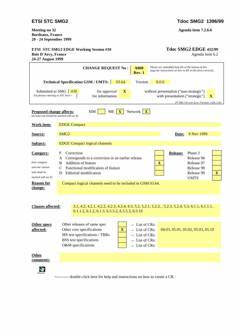
CHANGE REQUEST No : A060Rev. 1
Please see embedded help file at the bottom of thispage for instructions on how to fill in this form correctly.
Technical Specification GSM / UMTS: 03.64 Version 8.0.0
Submitted to SMG #30 for approval X without presentation ("non-strategic")list plenary meeting or STC here ↑ for information with presentation ("strategic") X
PT SMG CR cover form. Filename: crf26_3.doc
Proposed change affects: SIM ME X Network X(at least one should be marked with an X)
Work item: EDGE Compact
Source: SMG2 Date: 9 Nov 1999
Subject: EDGE Compact logical channels
Category: F Correction Release: Phase 2A Corresponds to a correction in an earlier release Release 96
(one category B Addition of feature X Release 97and one release C Functional modification of feature Release 98only shall be D Editorial modification Release 99 Xmarked with an X) UMTSReason forchange:
Compact logical channels need to be included in GSM 03.64.
Clauses affected: 3.1, 4.2, 4.2.1, 4.2.2, 4.2.3, 4.2.4, 4.3, 5.2, 5.2.1, 5.2.2, , 5.2.3, 5.2.4, 5.3, 6.1.1, 6.1.1.1,6.1.1.2, 6.1.2, 6.1.3, 6.5.5.2, 6.5.5.3, 6.5.10
Other specs Other releases of same spec → List of CRs:affected: Other core specifications X → List of CRs: 04.03, 05.01, 05.02, 05.03, 05.10
MS test specifications / TBRs → List of CRs:BSS test specifications → List of CRs:O&M specifications → List of CRs:
Othercomments:
help.doc
<--------- double-click here for help and instructions on how to create a CR.

Page 2
3.1 AbbreviationsIn addition to abbreviations in GSM 01.04 and GSM 02.60 following abbreviations apply:
ARQ Automatic Repeat reQuestBCS Block Check SequenceBEC Backward Error CorrectionBH Block HeaderCFCCH Compact Frequency Correction ChannelCPAGCH Compact Packet Access Grant ChannelCPBCCH Compact Packet Broadcast Control ChannelCPCCCH Compact Packet Common Control ChannelCPNCH Compact Packet Notification Channel (for PTM-M on CPCCCH)CPPCH Compact Packet Paging ChannelCPRACH Compact Packet Random Access ChannelCSCH Compact Synchronization ChannelCS Coding SchemeCU Cell UpdateEGPRS Enhanced GPRSFBI Final Block IndicatorFH Frame HeaderGGSN Gateway GPRS Support NodeHCS Header Check SequenceIR Incremental RedundancyLLC Logical Link ControlMAC Medium Access ControlMCS Modulation and Coding SchemeNCH Notification Channel (for PTM-M on CCCH)NSS Network and Switching SubsystemPACCH Packet Associate Control ChannelPAGCH Packet Access Grant ChannelPBCCH Packet Broadcast Control ChannelPC Power ControlPCCCH Packet Common Control ChannelPDCH Packet Data ChannelPDTCH Packet Data Traffic ChannelPDU Protocol Data UnitPL Physical LinkPNCH Packet Notification Channel (for PTM-M on PCCCH)PPCH Packet Paging ChannelPRACH Packet Random Access ChannelPSI Packet System InformationPTCCH Packet Timing Advance Control ChannelRLC Radio Link ControlSGSN Serving GPRS Support NodeSNDC Subnetwork Dependent ConvergenceTA Timing AdvanceTBF Temporary Block FlowTFI Temporary Frame IdentityUSF Uplink State Flag

Page 3
4.2 Packet Common Control Channel (PCCCH) and Compact(CPCCCH)
PCCCH and CPCCCH comprises logical channels for common control signalling used for packet data as described inthe following subclauses.
4.2.1 Packet Random Access Channel (PRACH) and Compact PacketRandom Access Channel (CPRACH) - uplink only
PRACH and CPRACH areis used by MS to initiate uplink transfer for sending data or signalling information. PacketAccess burst and Extended Packet Access burst are used on PRACH. Extended Packet Access burst is used onCPRACH [12].
4.2.2 Packet Paging Channel (PPCH) and Compact Packet PagingChannel (CPPCH) - downlink only
PPCH and CPPCH areis used to page an MS prior to downlink packet transfer. PPCH and CPPCH uses paging groupsin order to allow usage of DRX mode. PPCH can be used for paging of both circuit switched and packet data services.The paging for circuit switched services on PPCH is applicable for class A and B GPRS MSs in Network operationmode I, see GSM 03.60.
4.2.3 Packet Access Grant Channel (PAGCH) and Compact PacketAccess Grant Channel (CPAGCH) - downlink only
PAGCH and CPAGCH areis used in the packet transfer establishment phase to send resource assignment to an MSprior to packet transfer.
4.2.4 Packet Notification Channel (PNCH) and Compact PacketNotification Channel (CPNCH) - downlink only
PNCH and CPNCH areis used to send a PTM-M (Point To Multipoint - Multicast) notification to a group of MSs priorto a PTM-M packet transfer.
DRX mode shall be provided for monitoring PNCH and CPNCH. Furthermore, a “PTM-M new message” indicatormay optionally be sent on all individual paging channels to inform MSs interested in PTM-M when they need to listento PNCH and CPNCH.
The PTM-M service is not specified in GPRS Phase 1.
4.3 Packet Broadcast Control Channel (PBCCH) and CompactPacket Broadcast Control Channel (CPBCCH) - downlinkonly
PBCCH and CPBCCH broadcasts packet data specific System Information. If PBCCH is not allocated, the packet dataspecific system information is broadcast on BCCH. For Compact, CPBCCH shall be allocated. CPBCCH and BCCHare mutually exclusive.

Page 4
5.1 GeneralDifferent packet data logical channels can occur on the same physical channel (i.e. PDCH). The sharing of the physicalchannel is based on blocks of 4 consecutive bursts, except for PTCCH. The mapping in frequency of PDCH on to thephysical channel shall be as defined in GSM 05.02.
GPRS and EGPRS employ the same physical layer, except for the PDTCH.
On PRACH, CPRACH, and PTCCH/U, access bursts are used. On all other packet data logical channels, radio blockscomprising 4 normal bursts are used. The only exception is some messages on uplink PACCH which comprise 4consecutive access bursts (to increase robustness).
5.2 Packet Common Control Channels (PCCCH and CPCCCH)At a given time, the logical channels of the PCCCH are mapped on different physical resources than the logicalchannels of the CCCH.
The PCCCH and CPCCCH does not have to be allocated permanently in the cell. Whenever the PCCCH is notallocated, the CCCH shall be used to initiate a packet transfer. For Compact, CPCCCH shall be allocated.
One given MS may use only a subset of the PCCCH and CPCCCH, the subset being mapped onto one physical channel(i.e. PDCH).
The PCCCH, when it exists:
- is mapped on one or several physical channels according to a 52-multiframe, In that case the PCCCH, PBCCHand PDTCH share same physical channels (PDCHs).
The existence and location of the PCCCH shall be broadcast on the cell [6].
Since GSM phase 1 and phase 2 MS can only see and use the CCCH, the use on the PCCCH can be optimised forGPRS e.g. a PRACH of 11 bits can be used on uplink.
For Compact, one radio frequency channel of the cell allocation shall be used to carry synchronization information andthe CPBCCH, this shall be known as the primary Compact carrier. All other radio frequency channels of the cellallocation shall be known as secondary Compact carriers.
For primary and secondary Compact carriers, CPCCCHs shall be allocated on only one timeslot (which is associatedwith a time group as defined in GSM 05.02). This time group is known as the serving time group and rotates over oddtimeslot numbers as follows: 7, 5, 3, 1, 7, 5, …. The CPCCCH is mapped according to a Compact 52-multiframe andthe serving time group rotation occurs between frame numbers (FN) mod 52 = 3 and 4.
5.2.1 Packet Random Access Channel (PRACH and CPRACH)
The PRACH and CPRACH areis mapped on one or several physical channels. The physical channels on which thePRACH is mapped are derived by the MS from information broadcast on the PBCCH or BCCH. The physical channelson which the CPRACH is mapped are derived by the MS from information broadcast on the CPBCCH.
PRACH and CPRACH areis determined by the Uplink State Flag marked as free that is broadcast continuously on thecorresponding downlink (see subclause 6.6.4.1). Additionally, a predefined fixed part of the multiframe structure forPDCH can be used as PRACH or CPRACH only and the information about the mapping on the physical channel isbroadcast on PBCCH or CPBCCH. During those time periods an MS does not have to monitor the USF that issimultaneously broadcast on the downlink.
5.2.2 Packet Paging Channel (PPCH and CPPCH)
The PPCH and CPPCH areis mapped on one or several physical channels. The exact mapping on each physical channelfollows a predefined rule (see subclause 6.1.2), as it is done for the PCH.
The physical channels on which the PPCH or CPPCH areis mapped, as well as the rule that is followed on the physicalchannels, are derived by the MS from information broadcast on the PBCCH or CPBCCH.

Page 5
5.2.3 Packet Access Grant Channel (PAGCH and CPAGCH)
The PAGCH and CPAGCH areis mapped on one or several physical channels. The exact mapping on each physicalchannel follows a predefined rule (see subclause 6.1.2).
The physical channels on which the PAGCH or CPAGCH areis mapped, as well as the rule that is followed on thephysical channels, are derived by the MS from information broadcast on the PBCCH or CPBCCH.
5.2.4 Packet Notification Channel (PNCH and CPNCH)
The PNCH and CPNCH areis mapped on one or several blocks on PCCCH and CPCCCH. The exact mapping follows apredefined rule. The mapping is derived by the MS from information broadcast on the PBCCH or CPBCCH.
5.3 Packet Broadcast Control Channel (PBCCH and CPBCCH)The PBCCH and CPBCCH shall be mapped on one or several physical channels. The exact mapping on each physicalchannel follows a predefined rule (see subclause 6.1.2), as it is done for the BCCH. For Compact, CPBCCH shall beallocated. CPBCCH and BCCH are mutually exclusive.
The existence of the PCCCH, and consequently the existence of the PBCCH, is indicated on the BCCH.
For Compact, one radio frequency channel of the cell allocation shall be used to carry synchronization information andthe CPBCCH, this shall be known as the primary Compact carrier. All other radio frequency channels of the cellallocation shall be known as secondary Compact carriers.
The CPBCCH shall be mapped on only one timeslot (which is associated with a time group as defined in GSM 05.02).This time group is known as the serving time group and rotates over odd timeslot numbers as follows: 7, 5, 3, 1, 7, 5,…. The CPBCCH is mapped according to a Compact 52-multiframe and the serving time group rotation occursbetween frame numbers (FN) mod 52 = 3 and 4. The exact mapping follows a predefined rule (see subclause 6.1.2).
5.3a Compact Frequency Correction Channel (CFCCH)The CFCCH is the same as the FCCH with one exception the FCCH is mapped onto a 51-multiframe as defined inGSM 05.02.
5.3b Compact Synchronization Channel (CSCH)The CSCH is similar to the SCH. The major difference is that the SCH is mapped onto a 51-multiframe as defined inGSM 05.02. This results in a different layout for the reduced TDMA frame number (RFN).

Page 6
6.1 Radio Resource management principles
6.1.1 Allocation of resources for the GPRS
A cell supporting GPRS may allocate resources on one or several physical channels in order to support the GPRStraffic. Those physical channels (i.e. PDCHs), shared by the GPRS MSs, are taken from the common pool of physicalchannels available in the cell. The allocation of physical channels to circuit switched services and GPRS is donedynamically according to the "capacity on demand" principles described below.
Common control signalling required by GPRS in the initial phase of the packet transfer is conveyed on PCCCH, whenallocated, or on CCCH. This allows the operator to have capacity allocated specifically to GPRS in the cell only when apacket is to be transferred.
For Compact, common control signaling required by the mobile station in the initial phase of the packet transfer isconveyed on CPCCCH.
6.1.1.1 Master-Slave concept
At least one PDCH, acting as a master, accommodates packet common control channels that carry all the necessarycontrol signalling for initiating packet transfer (i.e. PCCCH), whenever that signalling is not carried by the existingCCCH, as well as user data and dedicated signalling (i.e. PDTCH and PACCH). Other PDCHs, acting as slaves, areused for user data transfer and for dedicated signalling.
For Compact, one radio frequency channel of the cell allocation shall be used to carry synchronization information andthe CPBCCH, this shall be known as the primary Compact carrier. All other radio frequency channels of the cellallocation shall be known as secondary Compact carriers.
For the primary Compact carrier, timeslot numbers (TN) 1, 3, 5, and 7, acting as a master, accommodate packetcommon control channels that carry all necessary control signalling for initiating packet transfer as well as user data anddedicated signalling (i.e., PDTCH and PACCH). TNs 0, 2, 4, and 6, acting as slaves, are used for user data transfer andfor dedicated signalling.
For the secondary Compact carrier(s) carrying CPCCCH, timeslot numbers (TN) 1, 3, 5, and 7, acting as a master,accommodate packet common control channels that carry all necessary control signalling for initiating packet transferas well as user data and dedicated signalling. TNs 0, 2, 4, and 6, acting as slaves, are used for user data transfer and fordedicated signalling.
For the secondary Compact carrier(s) not carrying CPCCCH, timeslot numbers (TN) 0 through 7, acting as slaves, areused for user data transfer and for dedicated signalling.
6.1.1.2 Capacity on demand concept
The GPRS does not require permanently allocated PDCHs. The allocation of capacity for GPRS can be based on theneeds for actual packet transfers which is here referred to as the "capacity on demand" principle. The operator can, aswell, decide to dedicate permanently or temporarily some physical resources (i.e. PDCHs) for the GPRS traffic.
When the PDCHs are congested due to the GPRS traffic load and more resources are available in the cell, the Networkcan allocate more physical channels as PDCHs.
However, the existence of PDCH(s) does not imply the existence of PCCCH.
When no PCCCH is allocated in a cell, all GPRS attached MSs camp on the CCCH.
In response to a Packet Channel Request sent on CCCH from the MS that wants to transmit GPRS packets, the networkcan assign resources on PDCH(s) for the uplink transfer.. After the transfer, the MS returns to CCCH. [6]
When PCCCH is allocated in a cell, all GPRS attached MSs camp on it. PCCCH can be allocated either as the result ofthe increased demand for packet data transfers or whenever there is enough available physical channels in a cell (toincrease the quality of service). The information about PCCCH is broadcast on BCCH. When the PCCCH capacity isinadequate, it is possible to allocate additional PCCCH resources on one or several PDCHs. If the network releases thelast PCCCH, the MS performs cell re-selection.

Page 7
For Compact, CPBCCH shall be allocated. CPBCCH is a stand-alone packet control channel for Compact. CPCCCHshall be allocated. The information about CPCCCH is broadcast on CPBCCH. When CPCCCH capacity is inadequate,it is possible to allocate additional CPCCCH resources on primary and secondary Compact carriers.
6.1.2 Multiframe structure for PDCH
NOTE: The text in this clause is informative. The normative text is in GSM 05.02. Where there is a conflictbetween these descriptions, the normative text has precedence.
The mapping in time of the logical channels is defined by a multiframe structure. The multiframe structure for PDCHconsists of 52 TDMA frames, divided into 12 blocks (of 4 frames), 2 idle frames and 2 frames used for the PTCCHaccording to Figure 2.
52 TDMA Frames
B0 B1 B2 T B3 B4 B5 X B6 B7 B8 T B9 B10 B11 X
X = Idle frameT = Frame used for PTCCH
B0 - B11 = Radio blocks
Figure 2: Multiframe structure for PDCH
The mapping of logical channels onto the radio blocks is defined in the rest of this subclause by means of the orderedlist of blocks (B0, B6, B3, B9, B1, B7, B4, B10, B2, B8, B5, B11).
One PDCH that contains PCCCH (if any) is indicated on BCCH. That PDCH is the only one that contains PBCCHblocks. On the downlink of this PDCH, the first block (B0) in the ordered list of blocks is used as PBCCH. If required,up to 3 more blocks on the same PDCH can be used as additional PBCCH. Any additional PDCH containing PCCCH isindicated on PBCCH.
On any PDCH with PCCCH (with or without PBCCH), the next up to 12 blocks in the ordered list of blocks are usedfor PAGCH, PNCH, PDTCH or PACCH in the downlink. The remaining blocks in the ordered list are used for PPCH,PAGCH, PNCH, PDTCH or PACCH in the downlink. In all cases, the actual usage of the blocks is indicated by themessage type. On an uplink PDCH that contains PCCCH, all blocks in the multiframe can be used as PRACH, PDTCHor PACCH. Optionally, the first blocks in the ordered list of blocks can only used as PRACH. The MS may chose toeither ignore the USF (consider it as FREE) or use the USF to determine the PRACH in the same way as for the otherblocks.
The mapping of channels on multiframes are controlled by several parameters broadcast on PBCCH.
On a PDCH that does not contain PCCCH, all blocks can be used as PDTCH or PACCH. The actual usage is indicatedby the message type.
Two frames are used for PTCCH (see GSM 05.02) and the two idle frames as well as the PTCCH frames can be usedby the MS for signal measurements and BSIC identification.
6.1.2a Multiframe structure for Compact PDCH
NOTE: The text in this clause is informative. The normative text is in GSM 05.02. Where there is a conflictbetween these descriptions, the normative text has precedence.
For Compact, one radio frequency channel of the cell allocation shall be used to carry synchronization information andthe CPBCCH, this shall be known as the primary Compact carrier. All other radio frequency channels of the cellallocation shall be known as secondary Compact carriers.
For the primary Compact carrier, timeslot numbers (TN) 1, 3, 5, and 7 accommodate packet common control channels(i.e., CPBCCH and CPCCCH) as well as user data and dedicated signalling (i.e., PDTCH and PACCH). TNs 0, 2, 4,and 6 are used for user data transfer and for dedicated signalling.
For the secondary Compact carrier(s) carrying CPCCCH, timeslot numbers (TN) 1, 3, 5, and 7 accommodate packetcommon control channels as well as user data and dedicated signalling. TNs 0, 2, 4, and 6 are used for user data transferand for dedicated signalling.

Page 8
For the secondary Compact carrier(s) not carrying CPCCCH, timeslot numbers (TN) 0 through 7 are used for user datatransfer and for dedicated signalling.
For Compact, a base station is typically assigned at least 3 frequencies (one per cell which translates into one primaryCompact carrier per cell allocation) using a 1/3 frequency re-use pattern. Each cell is assigned one time group basedupon which timeslot number is allocated for control (see GSM 05.02). This is known as the serving time group.
Timeslot mapping and rotation of the control channels is used such that control channels belonging to a serving timegroup are rotated over odd timeslot numbers as follows: 7, 5, 3, 1, 7, 5 … . The rotation occurs between frame numbers(FN) mod 52 = 3 and 4. Packet switched logical channels PDTCH, PACCH, and PTCCH are never rotated.
For Compact, packet switched logical channels are mapped onto a Compact 52-multiframe. A Compact 52-multiframeconsists of 12 blocks of 4 consecutive frames, 2 idle frames (which can be used for CFCCH and CSCH), and 2 framesused for PTCCH (see GSM 05.02 and 05.10) as shown in Figure 2. A block allocated to a given logical channelcomprises one radio block or, in uplink only, 4 random access bursts. The type of channel may vary on a block by blockbasis.
The mapping of CPBCCH onto the radio blocks is defined by means of the ordered list of blocks (B0, B6, B3, B9, B1,B7, B4, B10, B2, B8, B5, B11). On the downlink of the primary Compact carrier, the first block (B0) shall be used asCPBCCH. If required, up to 3 more blocks on the primary Compact carrier can be used as additional CPBCCH. Thenext up to 12 blocks in the ordered list of blocks are used for CPAGCH, CPNCH, PDTCH, and PACCH in thedownlink. The remaining blocks in the ordered list are used for CPPCH, CPAGCH, and CPNCH in the downlink. In allcases, the actual usage of the blocks is indicated by the message type. The same applies to secondary Compact carriers.
In the uplink of the primary Compact carrier and secondary Compact carrier(s), all blocks in the multiframe can be usedas CPRACH. However, a prioritization scheme is recommended (see GSM 05.02). The MS may chose to either ignorethe USF (consider it as FREE) or use the USF to determine the CPRACH in the same way as for the other blocks.Optionally, the first blocks in the ordered list of blocks can only be used as CPRACH.
The mapping of channels on multiframes are controlled by several parameters broadcast on CPBCCH.
6.1.3 Scheduling of PBCCH information.
An MS attached to GPRS shall not be required to monitor BCCH if a PBCCH exists. All system information relevantfor GPRS and some information relevant for circuit switched services (e.g. the access classes) shall in this case bebroadcast on PBCCH. For Compact, CPBCCH shall be allocated. CPBCCH and BCCH are mutually exclusive.
In order to facilitate the MS operation, the network is required to transmit certain types of Packet System Information(PSI) messages in specific multiframes and specific PBCCH or CPBCCH blocks within the multiframes. The exactscheduling is in GSM 05.02.
When no PCCCH is allocated, the MS camps on CCCH and receives all system information on BCCH. Any necessaryGPRS specific system information shall in that case be broadcast on BCCH. For Compact, CPCCCH shall be allocated.

Page 9
6.5.5.2 Channel coding for PACCH, PBCCH, PAGCH, PPCH,PNCH and PTCCH
The channel coding for the PACCH, PBCCH, PAGCH, PPCH,PNCH and downlink PTCCH is the same as the codingscheme CS-1 presented in subclause 6.5.5.1.
The coding scheme used for uplink PTCCH is the same as for PRACH.
6.5.5.2a Channel coding for CPBCCH, CPAGCH, CPPCH, CPNCH, and CSCH
The channel coding for the CPBCCH, CPAGCH, CPPCH, and CPNCH is the same as the coding scheme CS-1presented in subclause 6.5.5.1. The channel coding for the CSCH is identical to SCH.
6.5.5.3 Channel Coding for the PRACH and CPRACH
Two types of packet access burst may be transmitted on the PRACH: an 8 information bits access burst or an 11information bits access burst called the extended packet access burst. The mobile shall support both access bursts. Thechannel coding for both burst formats is indicated in the following subclauses. Only the 11 information bits access burstmay be transmitted on the CPRACH.
6.5.5.3.1 Coding of the 8 data bit Packet Access Burst
The channel coding used for the burst carrying the 8 data bit packet access uplink message is identical to the coding ofthe access burst as defined for random access channel in GSM 05.03.
6.5.5.3.2 Coding of the 11 data bit Packet Access Burst
The channel coding for 11 bit access burst is the punctured version of the same coding as used for 8 bit access burst.

Page 10
6.5.10 Discontinuous Reception (DRX)
NOTE: The text in this subclause is informative. The normative text is in GSM 05.02. Where there is a conflictbetween these descriptions, the normative text has precedence.
DRX (sleep mode) shall be supported when the MS is in Packet Idle mode. DRX is independent from MM states Readyand Standby.
Negotiation of DRX parameters is per MS. An MS may choose to use DRX or not together with some operatingparameters. The following parameters are established:
- DRX/non-DRX indicatorIt indicates whether the MS uses DRX or not.
- DRX periodA conditional parameter for MSs using DRX to determine the right paging group. The DRX period is defined bythe parameter SPLIT_PG_CYCLE.
- Non-DRX timerA conditional parameter for MSs using DRX to determine the time period within which the non-DRX mode iskept after leaving the Transfer state. The support for this feature is optional on the network side and theinformation about the maximum supported value for the timer in the cell is broadcast on PBCCH.
An MS in DRX mode is only required to monitor the radio blocks defined by its paging group as definedin GSM 05.02.
Paging group definition based on SPLIT_PG_CYCLE is optional on CCCH for both BTS and MS. If not supported, thedefinition based on BS_PA_MFRMS shall be used. The parameters used to define the paging group for GPRS areshown in the Table 5, together with the corresponding GSM parameters. BS_PCC_CHANS is the number of PDCHscontaining PCCCH. For Compact, BS_PCC_CHANS is the number of radio frequency channels per cell carryingCPCCCHs including the radio frequency channel carrying the CPBCCH.
An MS in non-DRX mode is required to monitor all the radio blocks where PCCCH or (for Compact) CPCCCH may bemapped on the PDCH defined by its paging group.
When page for circuit-switched services is conveyed on PPCH, it follows the same scheduling principles as the page forpacket data. The same is valid for scheduling of resource assignments for downlink packet transfers for MSs in ReadyState (i.e. where no paging is performed).
The MS may need to monitor also PNCH or CPNCH in the case of PTM-M services.
NOTE: Paging reorganisation may be supported in the same way as for circuit switched GSM.
Table 5: Parameters for DRX operation
Parameter GPRS Corresponding GSMparameters
PCCCH CCCH CCCH
DRX period SPLIT_PG_CYCLE BS_PA_MFRMS *)SPLIT_PG_CYCLE **)
BS_PA_MFRMS
Blocks not available forPPCH or CPPCH per
multiframe
BS_PAG_BLKS_RES+ BS_PBCCH_BLKS
BS_AG_BLKS_RES BS_AG_BLKS_RES
Number of physical channelscontaining paging;
or
for Compact, number of radiofrequency channels per cell
carrying CPCCCHs including
BS_PCC_CHANS BS_CC_CHANS BS_CC_CHANS

Page 11
the radio frequency channelcarrying the CPBCCH.
*) Only when DRX period split is not supported.**) Only when DRX period split is supported.
ETSI STC SMG2 Tdoc SMG2 1399/99
Meeting no 32Bordeaux, France20 - 24 September 1999
IntroductionThis contribution provides a draft CR for COMPACT reselection impacts on GSM 03.64.
DescriptionThe concept description for GPRS-136HS EDGE describes a new COMPACT (possible to deploy in less than 1 MHzof spectrum) control channel option. The compact deployment is accomplished by synchronizing the base stations andtime sharing carriers in order to get higher effective re-use, than the 1/3 that is possible with 3 carrier frequencies.Dividing each carrier into 4 time groups accomplishes the time-sharing. This results in a discontinuous carrier for theCOMPACT control channels.
To be able to do correct neighbour cell measurements for COMPACT neighbours, a mobile station must know whichtime group a specific neighbour cell belongs to and a guaranteed amount of radio blocks that will contain controlinformation. Note that power must always be on for the control blocks, this is not true for traffic blocks where thepower will be off if there is no data to send. With this information the mobile station can calculate when it can performneighbour cell measurements on a particular neighbour cell.
It is possible that some operators may desire to utilize COMPACT control channels in some parts of their service areaand standard (Classic) control channels in other parts. In this kind of deployment, there will exist border areas betweenClassic and COMPACT, where reselection from Classic to COMPACT must be supported.
In order to support this scenario, a base station having at least one COMPACT neighbor cell, must be synchronizedwith the latter.
This CR contains the necessary changes to 03.64 to support base station synchronization.

ETSI STC SMG2 Tdoc SMG2 1399/99
Meeting no 32Bordeaux, France20 - 24 September 1999
CHANGE REQUEST No : A059 rev1 Please see embedded help file at the bottom of thispage for instructions on how to fill in this form correctly.
Technical Specification GSM / UMTS: 03.64 Version: 8.0.0
Submitted to SMG #30 for approval X without presentation ("non-strategic")list SMG plenary meeting no. here ↑ for information with presentation ("strategic") X
PT SMG CR cover form. Filename: crf26_3.doc
Proposed change affects: SIM ME X Network X(at least one should be marked with an X)
Work item: EDGE Compact and support for EGPRS in ANSI-136 networks
Source: SMG2 Date: 1999-11-09
Subject: EDGE COMPACT Cell Reselection
Category: F Correction Release: Phase 2A Corresponds to a correction in an earlier release Release 96
(one category B Addition of feature X Release 97and one release C Functional modification of feature Release 98only shall be D Editorial modification Release 99 Xmarked with an X) UMTS
Reason forchange:
To support COMPACT. The changes are required to specify neighbour measurements atreselection.
Clauses affected: 6.5.6.1
Other specs Other releases of same spec → List of CRs:affected: Other core specifications X → List of CRs: 05.02, 05.08, 04.08, 04.60
MS test specifications / TBRs → List of CRs:BSS test specifications → List of CRs:O&M specifications → List of CRs:
Othercomments:
help.doc
<--------- double-click here for help and instructions on how to create a CR.

ETSI
6.5.6.1 Measurements for Cell Re-selection
The MS shall measure the received RF signal strength on the BCCH frequencies of the serving cell and the neighbour cells asindicated in the BA-GPRS list, and calculate the received level average (RLA) for each frequency, as specified in GSM 05.08.In addition the MS shall verify the BSIC of the cells. Only channels with the same BSIC as broadcast together with BA-GPRSon PBCCH shall be considered for re-selection.
A COMPACT capable MS shall in addition perform the above tasks for any CPBCCH, either transmitted in the serving cell orindicated, by way of frequency and time group in the BA-GPRS list.
Any cell having a CPBCCH indicated in the BA-GPRS list shall be time synchronized to that cell, as specified in GSM 05.10.
When the number of downlink PDCHs assigned to certain types of multislot MS (see GSM 05.02, annex B) does not allowthem to perform measurements within the TDMA frame, the network shall provide measurement windows to ensure that theMS can perform a required number of measurements. The network shall provide periods of inactivity during a fixed allocationto allow the MS to make adjacent cell power measurements and BSIC detection.