ethernet media access controller (emac) user's guide for
TRANSCRIPT
KeyStone Architecture
Literature Number: SPRUHH1July 2012
Ethernet Media Access Controller (EMAC)/ Management Data Input/Output (MDIO)
User Guide
ø-ii KeyStone Architecture EMAC/MDIO User Guide SPRUHH1—July 2012Submit Documentation Feedback
—Release History www.ti.com
Release History
Release Date Description/Comments
SPRUHH1 July 2012 First Issue
Contents
SPRUHH1—July 2012 KeyStone Architecture EMAC/MDIO User Guide ø-iiiSubmit Documentation Feedback
www.ti.com
ContentsRelease History. . . . . . . . . . . . . . . . . . . . . . . . . . . . . . . . . . . . . . . . . . . . . . . . . . . . . . . . . . . . . . . . . . . . . . . . . . . . . . . . . . . . . . . . . . . . . . . . . . . . . . . ø-iiList of Figures . . . . . . . . . . . . . . . . . . . . . . . . . . . . . . . . . . . . . . . . . . . . . . . . . . . . . . . . . . . . . . . . . . . . . . . . . . . . . . . . . . . . . . . . . . . . . . . . . . . . . . . . ø-ixList of Tables . . . . . . . . . . . . . . . . . . . . . . . . . . . . . . . . . . . . . . . . . . . . . . . . . . . . . . . . . . . . . . . . . . . . . . . . . . . . . . . . . . . . . . . . . . . . . . . . . . . . . . . . ø-xiiList of Examples. . . . . . . . . . . . . . . . . . . . . . . . . . . . . . . . . . . . . . . . . . . . . . . . . . . . . . . . . . . . . . . . . . . . . . . . . . . . . . . . . . . . . . . . . . . . . . . . . . . . . ø-xvList of Procedures . . . . . . . . . . . . . . . . . . . . . . . . . . . . . . . . . . . . . . . . . . . . . . . . . . . . . . . . . . . . . . . . . . . . . . . . . . . . . . . . . . . . . . . . . . . . . . . . . . . ø-xvi
Preface ø-xviiAbout This Manual . . . . . . . . . . . . . . . . . . . . . . . . . . . . . . . . . . . . . . . . . . . . . . . . . . . . . . . . . . . . . . . . . . . . . . . . . . . . . . .ø-xviiNotational Conventions . . . . . . . . . . . . . . . . . . . . . . . . . . . . . . . . . . . . . . . . . . . . . . . . . . . . . . . . . . . . . . . . . . . . . . . . . .ø-xviiRelated Documentation from Texas Instruments . . . . . . . . . . . . . . . . . . . . . . . . . . . . . . . . . . . . . . . . . . . . . . . . . ø-xviiiTrademarks . . . . . . . . . . . . . . . . . . . . . . . . . . . . . . . . . . . . . . . . . . . . . . . . . . . . . . . . . . . . . . . . . . . . . . . . . . . . . . . . . . . . . ø-xviii
Chapter 1
Introduction 1-11.1 Purpose of the Peripheral . . . . . . . . . . . . . . . . . . . . . . . . . . . . . . . . . . . . . . . . . . . . . . . . . . . . . . . . . . . . . . . . . . . . . . 1-21.2 Features . . . . . . . . . . . . . . . . . . . . . . . . . . . . . . . . . . . . . . . . . . . . . . . . . . . . . . . . . . . . . . . . . . . . . . . . . . . . . . . . . . . . . . . 1-21.3 Functional Block Diagram . . . . . . . . . . . . . . . . . . . . . . . . . . . . . . . . . . . . . . . . . . . . . . . . . . . . . . . . . . . . . . . . . . . . . . 1-31.4 Industry Standard(s) Compliance Statement . . . . . . . . . . . . . . . . . . . . . . . . . . . . . . . . . . . . . . . . . . . . . . . . . . . . 1-4
Chapter 2
EMAC Functional Architecture 2-12.1 Clock Control . . . . . . . . . . . . . . . . . . . . . . . . . . . . . . . . . . . . . . . . . . . . . . . . . . . . . . . . . . . . . . . . . . . . . . . . . . . . . . . . . . 2-2
2.1.1 GMII Clocking . . . . . . . . . . . . . . . . . . . . . . . . . . . . . . . . . . . . . . . . . . . . . . . . . . . . . . . . . . . . . . . . . . . . . . . . . . . . . . . . . . . . . . . 2-22.1.2 SGMII Clocking. . . . . . . . . . . . . . . . . . . . . . . . . . . . . . . . . . . . . . . . . . . . . . . . . . . . . . . . . . . . . . . . . . . . . . . . . . . . . . . . . . . . . . 2-22.1.3 SGMII SerDes Clocking . . . . . . . . . . . . . . . . . . . . . . . . . . . . . . . . . . . . . . . . . . . . . . . . . . . . . . . . . . . . . . . . . . . . . . . . . . . . . . 2-2
2.2 Memory Map . . . . . . . . . . . . . . . . . . . . . . . . . . . . . . . . . . . . . . . . . . . . . . . . . . . . . . . . . . . . . . . . . . . . . . . . . . . . . . . . . . 2-32.3 System Level Connection . . . . . . . . . . . . . . . . . . . . . . . . . . . . . . . . . . . . . . . . . . . . . . . . . . . . . . . . . . . . . . . . . . . . . . 2-4
2.3.1 Serial Gigabit Media Independent Interface (SGMII) Connections . . . . . . . . . . . . . . . . . . . . . . . . . . . . . . . . . . . . . 2-42.4 Ethernet Protocol Overview . . . . . . . . . . . . . . . . . . . . . . . . . . . . . . . . . . . . . . . . . . . . . . . . . . . . . . . . . . . . . . . . . . . . 2-6
2.4.1 Ethernet Frame Format. . . . . . . . . . . . . . . . . . . . . . . . . . . . . . . . . . . . . . . . . . . . . . . . . . . . . . . . . . . . . . . . . . . . . . . . . . . . . . 2-62.4.2 Multiple Access Protocol . . . . . . . . . . . . . . . . . . . . . . . . . . . . . . . . . . . . . . . . . . . . . . . . . . . . . . . . . . . . . . . . . . . . . . . . . . . . 2-6
2.5 Programming Interface . . . . . . . . . . . . . . . . . . . . . . . . . . . . . . . . . . . . . . . . . . . . . . . . . . . . . . . . . . . . . . . . . . . . . . . . 2-82.5.1 Packet Buffer Descriptors. . . . . . . . . . . . . . . . . . . . . . . . . . . . . . . . . . . . . . . . . . . . . . . . . . . . . . . . . . . . . . . . . . . . . . . . . . . . 2-82.5.2 Transmit and Receive Descriptor Queues . . . . . . . . . . . . . . . . . . . . . . . . . . . . . . . . . . . . . . . . . . . . . . . . . . . . . . . . . . . . 2-92.5.3 Transmit and Receive EMAC Interrupts. . . . . . . . . . . . . . . . . . . . . . . . . . . . . . . . . . . . . . . . . . . . . . . . . . . . . . . . . . . . . .2-102.5.4 Transmit Buffer Descriptor Format . . . . . . . . . . . . . . . . . . . . . . . . . . . . . . . . . . . . . . . . . . . . . . . . . . . . . . . . . . . . . . . . . .2-11
2.5.4.1 Next Descriptor Pointer . . . . . . . . . . . . . . . . . . . . . . . . . . . . . . . . . . . . . . . . . . . . . . . . . . . . . . . . . . . . . . . . . . . . . .2-122.5.4.2 Buffer Pointer . . . . . . . . . . . . . . . . . . . . . . . . . . . . . . . . . . . . . . . . . . . . . . . . . . . . . . . . . . . . . . . . . . . . . . . . . . . . . . .2-122.5.4.3 Buffer Offset. . . . . . . . . . . . . . . . . . . . . . . . . . . . . . . . . . . . . . . . . . . . . . . . . . . . . . . . . . . . . . . . . . . . . . . . . . . . . . . . .2-122.5.4.4 Buffer Length. . . . . . . . . . . . . . . . . . . . . . . . . . . . . . . . . . . . . . . . . . . . . . . . . . . . . . . . . . . . . . . . . . . . . . . . . . . . . . . .2-132.5.4.5 Packet Length . . . . . . . . . . . . . . . . . . . . . . . . . . . . . . . . . . . . . . . . . . . . . . . . . . . . . . . . . . . . . . . . . . . . . . . . . . . . . . .2-132.5.4.6 Start-of-Packet (SOP) Flag. . . . . . . . . . . . . . . . . . . . . . . . . . . . . . . . . . . . . . . . . . . . . . . . . . . . . . . . . . . . . . . . . . . .2-132.5.4.7 End-of-Packet (EOP) Flag. . . . . . . . . . . . . . . . . . . . . . . . . . . . . . . . . . . . . . . . . . . . . . . . . . . . . . . . . . . . . . . . . . . . .2-132.5.4.8 Ownership (OWNER) Flag . . . . . . . . . . . . . . . . . . . . . . . . . . . . . . . . . . . . . . . . . . . . . . . . . . . . . . . . . . . . . . . . . . . .2-132.5.4.9 End-of-Queue (EOQ) flag. . . . . . . . . . . . . . . . . . . . . . . . . . . . . . . . . . . . . . . . . . . . . . . . . . . . . . . . . . . . . . . . . . . . .2-132.5.4.10 Teardown Complete (TDOWNCMPLT) Flag . . . . . . . . . . . . . . . . . . . . . . . . . . . . . . . . . . . . . . . . . . . . . . . . . .2-142.5.4.11 Pass CRC (PASSCRC) Flag . . . . . . . . . . . . . . . . . . . . . . . . . . . . . . . . . . . . . . . . . . . . . . . . . . . . . . . . . . . . . . . . . . .2-14
2.5.5 Receive Buffer Descriptor Format . . . . . . . . . . . . . . . . . . . . . . . . . . . . . . . . . . . . . . . . . . . . . . . . . . . . . . . . . . . . . . . . . . .2-142.5.5.1 Next Descriptor Pointer . . . . . . . . . . . . . . . . . . . . . . . . . . . . . . . . . . . . . . . . . . . . . . . . . . . . . . . . . . . . . . . . . . . . . .2-152.5.5.2 Buffer Pointer . . . . . . . . . . . . . . . . . . . . . . . . . . . . . . . . . . . . . . . . . . . . . . . . . . . . . . . . . . . . . . . . . . . . . . . . . . . . . . .2-152.5.5.3 Buffer Offset. . . . . . . . . . . . . . . . . . . . . . . . . . . . . . . . . . . . . . . . . . . . . . . . . . . . . . . . . . . . . . . . . . . . . . . . . . . . . . . . .2-15
Contents
ø-iv KeyStone Architecture EMAC/MDIO User Guide SPRUHH1—July 2012Submit Documentation Feedback
www.ti.com
2.5.5.4 Buffer Length. . . . . . . . . . . . . . . . . . . . . . . . . . . . . . . . . . . . . . . . . . . . . . . . . . . . . . . . . . . . . . . . . . . . . . . . . . . . . . . .2-162.5.5.5 Packet Length . . . . . . . . . . . . . . . . . . . . . . . . . . . . . . . . . . . . . . . . . . . . . . . . . . . . . . . . . . . . . . . . . . . . . . . . . . . . . . .2-162.5.5.6 Start-of-Packet (SOP) Flag. . . . . . . . . . . . . . . . . . . . . . . . . . . . . . . . . . . . . . . . . . . . . . . . . . . . . . . . . . . . . . . . . . . .2-162.5.5.7 End-of-Packet (EOP) Flag. . . . . . . . . . . . . . . . . . . . . . . . . . . . . . . . . . . . . . . . . . . . . . . . . . . . . . . . . . . . . . . . . . . . .2-162.5.5.8 Ownership (OWNER) Flag . . . . . . . . . . . . . . . . . . . . . . . . . . . . . . . . . . . . . . . . . . . . . . . . . . . . . . . . . . . . . . . . . . . .2-162.5.5.9 End-of-Queue (EOQ) Flag . . . . . . . . . . . . . . . . . . . . . . . . . . . . . . . . . . . . . . . . . . . . . . . . . . . . . . . . . . . . . . . . . . . .2-172.5.5.10 Teardown Complete (TDOWNCMPLT) Flag . . . . . . . . . . . . . . . . . . . . . . . . . . . . . . . . . . . . . . . . . . . . . . . . . .2-172.5.5.11 Pass CRC (PASSCRC) Flag . . . . . . . . . . . . . . . . . . . . . . . . . . . . . . . . . . . . . . . . . . . . . . . . . . . . . . . . . . . . . . . . . . .2-172.5.5.12 Jabber Flag . . . . . . . . . . . . . . . . . . . . . . . . . . . . . . . . . . . . . . . . . . . . . . . . . . . . . . . . . . . . . . . . . . . . . . . . . . . . . . . .2-172.5.5.13 Oversize Flag. . . . . . . . . . . . . . . . . . . . . . . . . . . . . . . . . . . . . . . . . . . . . . . . . . . . . . . . . . . . . . . . . . . . . . . . . . . . . . .2-172.5.5.14 Fragment Flag . . . . . . . . . . . . . . . . . . . . . . . . . . . . . . . . . . . . . . . . . . . . . . . . . . . . . . . . . . . . . . . . . . . . . . . . . . . . .2-172.5.5.15 Undersized Flag . . . . . . . . . . . . . . . . . . . . . . . . . . . . . . . . . . . . . . . . . . . . . . . . . . . . . . . . . . . . . . . . . . . . . . . . . . . .2-172.5.5.16 Control Flag. . . . . . . . . . . . . . . . . . . . . . . . . . . . . . . . . . . . . . . . . . . . . . . . . . . . . . . . . . . . . . . . . . . . . . . . . . . . . . . .2-172.5.5.17 Overrun Flag . . . . . . . . . . . . . . . . . . . . . . . . . . . . . . . . . . . . . . . . . . . . . . . . . . . . . . . . . . . . . . . . . . . . . . . . . . . . . . .2-182.5.5.18 Code Error (CODEERROR) Flag . . . . . . . . . . . . . . . . . . . . . . . . . . . . . . . . . . . . . . . . . . . . . . . . . . . . . . . . . . . . . .2-182.5.5.19 Alignment Error (ALIGNERROR) Flag . . . . . . . . . . . . . . . . . . . . . . . . . . . . . . . . . . . . . . . . . . . . . . . . . . . . . . . .2-182.5.5.20 CRC Error (CRCERROR) Flag . . . . . . . . . . . . . . . . . . . . . . . . . . . . . . . . . . . . . . . . . . . . . . . . . . . . . . . . . . . . . . . . .2-182.5.5.21 No Match (NOMATCH) Flag . . . . . . . . . . . . . . . . . . . . . . . . . . . . . . . . . . . . . . . . . . . . . . . . . . . . . . . . . . . . . . . . .2-18
2.6 EMAC Control Module . . . . . . . . . . . . . . . . . . . . . . . . . . . . . . . . . . . . . . . . . . . . . . . . . . . . . . . . . . . . . . . . . . . . . . . .2-192.6.1 Descriptor Memory . . . . . . . . . . . . . . . . . . . . . . . . . . . . . . . . . . . . . . . . . . . . . . . . . . . . . . . . . . . . . . . . . . . . . . . . . . . . . . . .2-192.6.2 Bus Arbiter. . . . . . . . . . . . . . . . . . . . . . . . . . . . . . . . . . . . . . . . . . . . . . . . . . . . . . . . . . . . . . . . . . . . . . . . . . . . . . . . . . . . . . . . .2-192.6.3 Interrupt Control . . . . . . . . . . . . . . . . . . . . . . . . . . . . . . . . . . . . . . . . . . . . . . . . . . . . . . . . . . . . . . . . . . . . . . . . . . . . . . . . . . .2-20
2.6.3.1 Transmit Interrupt Description . . . . . . . . . . . . . . . . . . . . . . . . . . . . . . . . . . . . . . . . . . . . . . . . . . . . . . . . . . . . . . .2-202.6.3.2 Receive Interrupt Description . . . . . . . . . . . . . . . . . . . . . . . . . . . . . . . . . . . . . . . . . . . . . . . . . . . . . . . . . . . . . . . .2-202.6.3.3 Receive Threshold Interrupt Description. . . . . . . . . . . . . . . . . . . . . . . . . . . . . . . . . . . . . . . . . . . . . . . . . . . . . .2-202.6.3.4 Miscellaneous Interrupt Description. . . . . . . . . . . . . . . . . . . . . . . . . . . . . . . . . . . . . . . . . . . . . . . . . . . . . . . . . .2-212.6.3.5 Interrupt Pacing . . . . . . . . . . . . . . . . . . . . . . . . . . . . . . . . . . . . . . . . . . . . . . . . . . . . . . . . . . . . . . . . . . . . . . . . . . . . .2-21
2.7 Management Data Input/Output (MDIO) Module . . . . . . . . . . . . . . . . . . . . . . . . . . . . . . . . . . . . . . . . . . . . . .2-222.7.1 MDIO Module Components . . . . . . . . . . . . . . . . . . . . . . . . . . . . . . . . . . . . . . . . . . . . . . . . . . . . . . . . . . . . . . . . . . . . . . . .2-22
2.7.1.1 MDIO Clock Generator . . . . . . . . . . . . . . . . . . . . . . . . . . . . . . . . . . . . . . . . . . . . . . . . . . . . . . . . . . . . . . . . . . . . . . .2-222.7.1.2 Global PHY Detection and Link State Monitoring . . . . . . . . . . . . . . . . . . . . . . . . . . . . . . . . . . . . . . . . . . . . .2-232.7.1.3 Active PHY Monitoring. . . . . . . . . . . . . . . . . . . . . . . . . . . . . . . . . . . . . . . . . . . . . . . . . . . . . . . . . . . . . . . . . . . . . . .2-232.7.1.4 PHY Register User Access . . . . . . . . . . . . . . . . . . . . . . . . . . . . . . . . . . . . . . . . . . . . . . . . . . . . . . . . . . . . . . . . . . . .2-23
2.7.2 MDIO Module Operational Overview . . . . . . . . . . . . . . . . . . . . . . . . . . . . . . . . . . . . . . . . . . . . . . . . . . . . . . . . . . . . . . .2-232.7.2.1 Initializing the MDIO Module. . . . . . . . . . . . . . . . . . . . . . . . . . . . . . . . . . . . . . . . . . . . . . . . . . . . . . . . . . . . . . . . .2-242.7.2.2 Writing Data to a PHY Register . . . . . . . . . . . . . . . . . . . . . . . . . . . . . . . . . . . . . . . . . . . . . . . . . . . . . . . . . . . . . . .2-242.7.2.3 Reading Data From a PHY Register . . . . . . . . . . . . . . . . . . . . . . . . . . . . . . . . . . . . . . . . . . . . . . . . . . . . . . . . . . .2-252.7.2.4 Example of MDIO Register Access Code . . . . . . . . . . . . . . . . . . . . . . . . . . . . . . . . . . . . . . . . . . . . . . . . . . . . . .2-25
2.8 EMAC Module . . . . . . . . . . . . . . . . . . . . . . . . . . . . . . . . . . . . . . . . . . . . . . . . . . . . . . . . . . . . . . . . . . . . . . . . . . . . . . . .2-272.8.1 EMAC Module Components . . . . . . . . . . . . . . . . . . . . . . . . . . . . . . . . . . . . . . . . . . . . . . . . . . . . . . . . . . . . . . . . . . . . . . . .2-27
2.8.1.1 Receive DMA Engine. . . . . . . . . . . . . . . . . . . . . . . . . . . . . . . . . . . . . . . . . . . . . . . . . . . . . . . . . . . . . . . . . . . . . . . . .2-272.8.1.2 Receive FIFO . . . . . . . . . . . . . . . . . . . . . . . . . . . . . . . . . . . . . . . . . . . . . . . . . . . . . . . . . . . . . . . . . . . . . . . . . . . . . . . .2-282.8.1.3 MAC Receiver . . . . . . . . . . . . . . . . . . . . . . . . . . . . . . . . . . . . . . . . . . . . . . . . . . . . . . . . . . . . . . . . . . . . . . . . . . . . . . .2-282.8.1.4 Receive Address . . . . . . . . . . . . . . . . . . . . . . . . . . . . . . . . . . . . . . . . . . . . . . . . . . . . . . . . . . . . . . . . . . . . . . . . . . . . .2-282.8.1.5 Transmit DMA Engine . . . . . . . . . . . . . . . . . . . . . . . . . . . . . . . . . . . . . . . . . . . . . . . . . . . . . . . . . . . . . . . . . . . . . . .2-282.8.1.6 Transmit FIFO . . . . . . . . . . . . . . . . . . . . . . . . . . . . . . . . . . . . . . . . . . . . . . . . . . . . . . . . . . . . . . . . . . . . . . . . . . . . . . .2-282.8.1.7 MAC Transmitter . . . . . . . . . . . . . . . . . . . . . . . . . . . . . . . . . . . . . . . . . . . . . . . . . . . . . . . . . . . . . . . . . . . . . . . . . . . .2-282.8.1.8 Statistics Logic . . . . . . . . . . . . . . . . . . . . . . . . . . . . . . . . . . . . . . . . . . . . . . . . . . . . . . . . . . . . . . . . . . . . . . . . . . . . . .2-282.8.1.9 State RAM . . . . . . . . . . . . . . . . . . . . . . . . . . . . . . . . . . . . . . . . . . . . . . . . . . . . . . . . . . . . . . . . . . . . . . . . . . . . . . . . . . .2-282.8.1.10 EMAC Interrupt Controller . . . . . . . . . . . . . . . . . . . . . . . . . . . . . . . . . . . . . . . . . . . . . . . . . . . . . . . . . . . . . . . . . .2-292.8.1.11 Control Registers and Logic. . . . . . . . . . . . . . . . . . . . . . . . . . . . . . . . . . . . . . . . . . . . . . . . . . . . . . . . . . . . . . . . .2-292.8.1.12 Clock and Reset Logic . . . . . . . . . . . . . . . . . . . . . . . . . . . . . . . . . . . . . . . . . . . . . . . . . . . . . . . . . . . . . . . . . . . . . .2-29
2.8.2 EMAC Module Operational Overview . . . . . . . . . . . . . . . . . . . . . . . . . . . . . . . . . . . . . . . . . . . . . . . . . . . . . . . . . . . . . . .2-292.9 Media Independent Interfaces. . . . . . . . . . . . . . . . . . . . . . . . . . . . . . . . . . . . . . . . . . . . . . . . . . . . . . . . . . . . . . . . .2-31
2.9.1 Data Reception . . . . . . . . . . . . . . . . . . . . . . . . . . . . . . . . . . . . . . . . . . . . . . . . . . . . . . . . . . . . . . . . . . . . . . . . . . . . . . . . . . . .2-312.9.1.1 Receive Control . . . . . . . . . . . . . . . . . . . . . . . . . . . . . . . . . . . . . . . . . . . . . . . . . . . . . . . . . . . . . . . . . . . . . . . . . . . . .2-312.9.1.2 Receive Inter-Frame Interval . . . . . . . . . . . . . . . . . . . . . . . . . . . . . . . . . . . . . . . . . . . . . . . . . . . . . . . . . . . . . . . . .2-312.9.1.3 Receive Flow Control . . . . . . . . . . . . . . . . . . . . . . . . . . . . . . . . . . . . . . . . . . . . . . . . . . . . . . . . . . . . . . . . . . . . . . . .2-31
Contents
SPRUHH1—July 2012 KeyStone Architecture EMAC/MDIO User Guide ø-vSubmit Documentation Feedback
www.ti.com
2.9.1.4 Collision-Based Receive Buffer Flow Control . . . . . . . . . . . . . . . . . . . . . . . . . . . . . . . . . . . . . . . . . . . . . . . . . .2-322.9.1.5 IEEE 802.3X Based Receive Buffer Flow Control . . . . . . . . . . . . . . . . . . . . . . . . . . . . . . . . . . . . . . . . . . . . . . .2-32
2.9.2 Data Transmission . . . . . . . . . . . . . . . . . . . . . . . . . . . . . . . . . . . . . . . . . . . . . . . . . . . . . . . . . . . . . . . . . . . . . . . . . . . . . . . . .2-332.9.2.1 Transmit Control . . . . . . . . . . . . . . . . . . . . . . . . . . . . . . . . . . . . . . . . . . . . . . . . . . . . . . . . . . . . . . . . . . . . . . . . . . . .2-332.9.2.2 CRC Insertion. . . . . . . . . . . . . . . . . . . . . . . . . . . . . . . . . . . . . . . . . . . . . . . . . . . . . . . . . . . . . . . . . . . . . . . . . . . . . . . .2-332.9.2.3 Adaptive Performance Optimization (APO) . . . . . . . . . . . . . . . . . . . . . . . . . . . . . . . . . . . . . . . . . . . . . . . . . . .2-332.9.2.4 Interpacket-Gap (IPG) Enforcement . . . . . . . . . . . . . . . . . . . . . . . . . . . . . . . . . . . . . . . . . . . . . . . . . . . . . . . . . .2-342.9.2.5 Back Off . . . . . . . . . . . . . . . . . . . . . . . . . . . . . . . . . . . . . . . . . . . . . . . . . . . . . . . . . . . . . . . . . . . . . . . . . . . . . . . . . . . . .2-342.9.2.6 Transmit Flow Control . . . . . . . . . . . . . . . . . . . . . . . . . . . . . . . . . . . . . . . . . . . . . . . . . . . . . . . . . . . . . . . . . . . . . . .2-342.9.2.7 Speed, Duplex, and Pause Frame Support . . . . . . . . . . . . . . . . . . . . . . . . . . . . . . . . . . . . . . . . . . . . . . . . . . . .2-35
2.10 Packet Receive Operation . . . . . . . . . . . . . . . . . . . . . . . . . . . . . . . . . . . . . . . . . . . . . . . . . . . . . . . . . . . . . . . . . . . .2-362.10.1 Receive DMA Host Configuration . . . . . . . . . . . . . . . . . . . . . . . . . . . . . . . . . . . . . . . . . . . . . . . . . . . . . . . . . . . . . . . . . .2-362.10.2 Receive Channel Enabling. . . . . . . . . . . . . . . . . . . . . . . . . . . . . . . . . . . . . . . . . . . . . . . . . . . . . . . . . . . . . . . . . . . . . . . . .2-362.10.3 Receive Channel Addressing . . . . . . . . . . . . . . . . . . . . . . . . . . . . . . . . . . . . . . . . . . . . . . . . . . . . . . . . . . . . . . . . . . . . . .2-372.10.4 Hardware Receive QOS Support . . . . . . . . . . . . . . . . . . . . . . . . . . . . . . . . . . . . . . . . . . . . . . . . . . . . . . . . . . . . . . . . . . .2-372.10.5 Host Free Buffer Tracking . . . . . . . . . . . . . . . . . . . . . . . . . . . . . . . . . . . . . . . . . . . . . . . . . . . . . . . . . . . . . . . . . . . . . . . . .2-382.10.6 Receive Channel Teardown . . . . . . . . . . . . . . . . . . . . . . . . . . . . . . . . . . . . . . . . . . . . . . . . . . . . . . . . . . . . . . . . . . . . . . .2-382.10.7 Receive Frame Classification . . . . . . . . . . . . . . . . . . . . . . . . . . . . . . . . . . . . . . . . . . . . . . . . . . . . . . . . . . . . . . . . . . . . . .2-392.10.8 Promiscuous Receive Mode . . . . . . . . . . . . . . . . . . . . . . . . . . . . . . . . . . . . . . . . . . . . . . . . . . . . . . . . . . . . . . . . . . . . . . .2-392.10.9 Receive Overrun . . . . . . . . . . . . . . . . . . . . . . . . . . . . . . . . . . . . . . . . . . . . . . . . . . . . . . . . . . . . . . . . . . . . . . . . . . . . . . . . . .2-40
2.11 Packet Transmit Operation . . . . . . . . . . . . . . . . . . . . . . . . . . . . . . . . . . . . . . . . . . . . . . . . . . . . . . . . . . . . . . . . . . .2-422.11.1 Transmit DMA Host Configuration. . . . . . . . . . . . . . . . . . . . . . . . . . . . . . . . . . . . . . . . . . . . . . . . . . . . . . . . . . . . . . . . .2-422.11.2 Transmit Channel Teardown . . . . . . . . . . . . . . . . . . . . . . . . . . . . . . . . . . . . . . . . . . . . . . . . . . . . . . . . . . . . . . . . . . . . . .2-42
2.12 Receive and Transmit Latency . . . . . . . . . . . . . . . . . . . . . . . . . . . . . . . . . . . . . . . . . . . . . . . . . . . . . . . . . . . . . . . .2-432.13 Transfer Node Priority. . . . . . . . . . . . . . . . . . . . . . . . . . . . . . . . . . . . . . . . . . . . . . . . . . . . . . . . . . . . . . . . . . . . . . . .2-442.14 Reset Considerations . . . . . . . . . . . . . . . . . . . . . . . . . . . . . . . . . . . . . . . . . . . . . . . . . . . . . . . . . . . . . . . . . . . . . . . .2-45
2.14.1 Software Reset Considerations . . . . . . . . . . . . . . . . . . . . . . . . . . . . . . . . . . . . . . . . . . . . . . . . . . . . . . . . . . . . . . . . . . . .2-452.14.2 Hardware Reset Considerations . . . . . . . . . . . . . . . . . . . . . . . . . . . . . . . . . . . . . . . . . . . . . . . . . . . . . . . . . . . . . . . . . . .2-45
2.15 Initialization . . . . . . . . . . . . . . . . . . . . . . . . . . . . . . . . . . . . . . . . . . . . . . . . . . . . . . . . . . . . . . . . . . . . . . . . . . . . . . . . .2-462.15.1 EMAC Control Module Initialization. . . . . . . . . . . . . . . . . . . . . . . . . . . . . . . . . . . . . . . . . . . . . . . . . . . . . . . . . . . . . . . .2-462.15.2 MDIO Module Initialization . . . . . . . . . . . . . . . . . . . . . . . . . . . . . . . . . . . . . . . . . . . . . . . . . . . . . . . . . . . . . . . . . . . . . . . .2-472.15.3 EMAC Module Initialization. . . . . . . . . . . . . . . . . . . . . . . . . . . . . . . . . . . . . . . . . . . . . . . . . . . . . . . . . . . . . . . . . . . . . . . .2-47
2.16 Interrupt Support . . . . . . . . . . . . . . . . . . . . . . . . . . . . . . . . . . . . . . . . . . . . . . . . . . . . . . . . . . . . . . . . . . . . . . . . . . . .2-492.16.1 EMAC Module Interrupt Events and Requests . . . . . . . . . . . . . . . . . . . . . . . . . . . . . . . . . . . . . . . . . . . . . . . . . . . . . .2-49
2.16.1.1 Transmit Packet Completion Interrupts . . . . . . . . . . . . . . . . . . . . . . . . . . . . . . . . . . . . . . . . . . . . . . . . . . . . .2-492.16.1.2 Receive Packet Completion Interrupts . . . . . . . . . . . . . . . . . . . . . . . . . . . . . . . . . . . . . . . . . . . . . . . . . . . . . .2-502.16.1.3 Receive Threshold Interrupts . . . . . . . . . . . . . . . . . . . . . . . . . . . . . . . . . . . . . . . . . . . . . . . . . . . . . . . . . . . . . . .2-502.16.1.4 Statistics Interrupt. . . . . . . . . . . . . . . . . . . . . . . . . . . . . . . . . . . . . . . . . . . . . . . . . . . . . . . . . . . . . . . . . . . . . . . . . .2-512.16.1.5 Host Error Interrupt. . . . . . . . . . . . . . . . . . . . . . . . . . . . . . . . . . . . . . . . . . . . . . . . . . . . . . . . . . . . . . . . . . . . . . . . .2-51
2.16.2 MDIO Module Interrupt Events and Requests . . . . . . . . . . . . . . . . . . . . . . . . . . . . . . . . . . . . . . . . . . . . . . . . . . . . . .2-512.16.2.1 Link Change Interrupt . . . . . . . . . . . . . . . . . . . . . . . . . . . . . . . . . . . . . . . . . . . . . . . . . . . . . . . . . . . . . . . . . . . . . .2-512.16.2.2 User Access Completion Interrupt. . . . . . . . . . . . . . . . . . . . . . . . . . . . . . . . . . . . . . . . . . . . . . . . . . . . . . . . . . .2-52
2.16.3 Proper Interrupt Processing . . . . . . . . . . . . . . . . . . . . . . . . . . . . . . . . . . . . . . . . . . . . . . . . . . . . . . . . . . . . . . . . . . . . . . .2-522.16.4 Interrupt Multiplexing . . . . . . . . . . . . . . . . . . . . . . . . . . . . . . . . . . . . . . . . . . . . . . . . . . . . . . . . . . . . . . . . . . . . . . . . . . . .2-52
2.17 Pulse Interrupts. . . . . . . . . . . . . . . . . . . . . . . . . . . . . . . . . . . . . . . . . . . . . . . . . . . . . . . . . . . . . . . . . . . . . . . . . . . . . .2-532.17.1 Pulse Interrupt Description. . . . . . . . . . . . . . . . . . . . . . . . . . . . . . . . . . . . . . . . . . . . . . . . . . . . . . . . . . . . . . . . . . . . . . . .2-53
2.17.1.1 Transmit Packet Completion Interrupts . . . . . . . . . . . . . . . . . . . . . . . . . . . . . . . . . . . . . . . . . . . . . . . . . . . . .2-532.17.1.2 Receive Packet Completion Interrupts . . . . . . . . . . . . . . . . . . . . . . . . . . . . . . . . . . . . . . . . . . . . . . . . . . . . . .2-532.17.1.3 EMAC Event Connectivity. . . . . . . . . . . . . . . . . . . . . . . . . . . . . . . . . . . . . . . . . . . . . . . . . . . . . . . . . . . . . . . . . . .2-53
2.18 SGMII Interface . . . . . . . . . . . . . . . . . . . . . . . . . . . . . . . . . . . . . . . . . . . . . . . . . . . . . . . . . . . . . . . . . . . . . . . . . . . . . .2-542.18.1 Receive Interface . . . . . . . . . . . . . . . . . . . . . . . . . . . . . . . . . . . . . . . . . . . . . . . . . . . . . . . . . . . . . . . . . . . . . . . . . . . . . . . . .2-542.18.2 Transmit Interface . . . . . . . . . . . . . . . . . . . . . . . . . . . . . . . . . . . . . . . . . . . . . . . . . . . . . . . . . . . . . . . . . . . . . . . . . . . . . . . .2-542.18.3 Loopback. . . . . . . . . . . . . . . . . . . . . . . . . . . . . . . . . . . . . . . . . . . . . . . . . . . . . . . . . . . . . . . . . . . . . . . . . . . . . . . . . . . . . . . . .2-542.18.4 SGMII Mode-CPGMAC to PHY . . . . . . . . . . . . . . . . . . . . . . . . . . . . . . . . . . . . . . . . . . . . . . . . . . . . . . . . . . . . . . . . . . . . .2-55
2.19 SERDES Macro and Configurations . . . . . . . . . . . . . . . . . . . . . . . . . . . . . . . . . . . . . . . . . . . . . . . . . . . . . . . . . . .2-562.19.1 Enabling the PLL. . . . . . . . . . . . . . . . . . . . . . . . . . . . . . . . . . . . . . . . . . . . . . . . . . . . . . . . . . . . . . . . . . . . . . . . . . . . . . . . . .2-562.19.2 Enabling Transmitter. . . . . . . . . . . . . . . . . . . . . . . . . . . . . . . . . . . . . . . . . . . . . . . . . . . . . . . . . . . . . . . . . . . . . . . . . . . . . .2-572.19.3 Enabling Receiver. . . . . . . . . . . . . . . . . . . . . . . . . . . . . . . . . . . . . . . . . . . . . . . . . . . . . . . . . . . . . . . . . . . . . . . . . . . . . . . . .2-57
Contents
ø-vi KeyStone Architecture EMAC/MDIO User Guide SPRUHH1—July 2012Submit Documentation Feedback
www.ti.com
2.20 MAC Address . . . . . . . . . . . . . . . . . . . . . . . . . . . . . . . . . . . . . . . . . . . . . . . . . . . . . . . . . . . . . . . . . . . . . . . . . . . . . . . .2-592.21 Power Management . . . . . . . . . . . . . . . . . . . . . . . . . . . . . . . . . . . . . . . . . . . . . . . . . . . . . . . . . . . . . . . . . . . . . . . . .2-602.22 Emulation Considerations. . . . . . . . . . . . . . . . . . . . . . . . . . . . . . . . . . . . . . . . . . . . . . . . . . . . . . . . . . . . . . . . . . . .2-61
Chapter 3
EMAC Interrupt Controller Registers 3-13.1 Introduction . . . . . . . . . . . . . . . . . . . . . . . . . . . . . . . . . . . . . . . . . . . . . . . . . . . . . . . . . . . . . . . . . . . . . . . . . . . . . . . . . . . 3-23.2 Identification and Version Register (IDVER). . . . . . . . . . . . . . . . . . . . . . . . . . . . . . . . . . . . . . . . . . . . . . . . . . . . . . 3-33.3 Software Reset Register (SOFT_RESET) . . . . . . . . . . . . . . . . . . . . . . . . . . . . . . . . . . . . . . . . . . . . . . . . . . . . . . . . . . 3-43.4 Emulation Control Register (EM_CONTROL) . . . . . . . . . . . . . . . . . . . . . . . . . . . . . . . . . . . . . . . . . . . . . . . . . . . . . 3-53.5 Interrupt Control Register (INT_CONTROL) . . . . . . . . . . . . . . . . . . . . . . . . . . . . . . . . . . . . . . . . . . . . . . . . . . . . . . 3-63.6 Receive Threshold Enable Register (Cn_RX_THRESH_EN) . . . . . . . . . . . . . . . . . . . . . . . . . . . . . . . . . . . . . . . . 3-73.7 Receive Enable Register (Cn_RX_EN). . . . . . . . . . . . . . . . . . . . . . . . . . . . . . . . . . . . . . . . . . . . . . . . . . . . . . . . . . . . 3-83.8 Transmit Enable Register (Cn_TX_EN). . . . . . . . . . . . . . . . . . . . . . . . . . . . . . . . . . . . . . . . . . . . . . . . . . . . . . . . . . . 3-93.9 Miscellaneous Enable Register (Cn_MISC_EN) . . . . . . . . . . . . . . . . . . . . . . . . . . . . . . . . . . . . . . . . . . . . . . . . . .3-103.10 Receive Threshold Status Register (Cn_RX_THRESH_STAT) . . . . . . . . . . . . . . . . . . . . . . . . . . . . . . . . . . . .3-113.11 Receive Status Register (Cn_RX_STAT). . . . . . . . . . . . . . . . . . . . . . . . . . . . . . . . . . . . . . . . . . . . . . . . . . . . . . . .3-123.12 Transmit Status Register (Cn_TX_STAT) . . . . . . . . . . . . . . . . . . . . . . . . . . . . . . . . . . . . . . . . . . . . . . . . . . . . . . .3-133.13 Miscellaneous Status Register (Cn_MISC_STAT) . . . . . . . . . . . . . . . . . . . . . . . . . . . . . . . . . . . . . . . . . . . . . . .3-143.14 Receive Interrupts per Millisecond Register (Cn_RX_IMAX) . . . . . . . . . . . . . . . . . . . . . . . . . . . . . . . . . . . .3-153.15 Transmit Interrupts per Millisecond Register (Cn_TX_IMAX) . . . . . . . . . . . . . . . . . . . . . . . . . . . . . . . . . . .3-16
Chapter 4
EMAC Port Registers 4-14.1 Introduction . . . . . . . . . . . . . . . . . . . . . . . . . . . . . . . . . . . . . . . . . . . . . . . . . . . . . . . . . . . . . . . . . . . . . . . . . . . . . . . . . . . 4-34.2 Transmit Identification and Version Register (TXIDVER) . . . . . . . . . . . . . . . . . . . . . . . . . . . . . . . . . . . . . . . . . . 4-64.3 Transmit Control Register (TXCONTROL) . . . . . . . . . . . . . . . . . . . . . . . . . . . . . . . . . . . . . . . . . . . . . . . . . . . . . . . . 4-74.4 Transmit Teardown Register (TXTEARDOWN) . . . . . . . . . . . . . . . . . . . . . . . . . . . . . . . . . . . . . . . . . . . . . . . . . . . 4-84.5 Receive Identification and Version Register (RXIDVER) . . . . . . . . . . . . . . . . . . . . . . . . . . . . . . . . . . . . . . . . . . . 4-94.6 Receive Control Register (RXCONTROL) . . . . . . . . . . . . . . . . . . . . . . . . . . . . . . . . . . . . . . . . . . . . . . . . . . . . . . . .4-104.7 Receive Teardown Register (RXTEARDOWN) . . . . . . . . . . . . . . . . . . . . . . . . . . . . . . . . . . . . . . . . . . . . . . . . . . .4-114.8 Transmit Interrupt Status (Unmasked) Register (TXINTSTATRAW) . . . . . . . . . . . . . . . . . . . . . . . . . . . . . . .4-124.9 Transmit Interrupt Status (Masked) Register (TXINTSTATMASKED) . . . . . . . . . . . . . . . . . . . . . . . . . . . . . .4-134.10 Transmit Interrupt Mask Set Register (TXINTMASKSET) . . . . . . . . . . . . . . . . . . . . . . . . . . . . . . . . . . . . . . . .4-144.11 Transmit Interrupt Mask Clear Register (TXINTMASKCLEAR) . . . . . . . . . . . . . . . . . . . . . . . . . . . . . . . . . . .4-154.12 MAC Input Vector Register (MACINVECTOR) . . . . . . . . . . . . . . . . . . . . . . . . . . . . . . . . . . . . . . . . . . . . . . . . . .4-164.13 MAC End-of-Interrupt Vector Register (MACEOIVECTOR) . . . . . . . . . . . . . . . . . . . . . . . . . . . . . . . . . . . . . .4-174.14 Receive Interrupt Status (Unmasked) Register (RXINTSTATRAW) . . . . . . . . . . . . . . . . . . . . . . . . . . . . . . .4-184.15 Receive Interrupt Status (Masked) Register (RXINTSTATMASKED) . . . . . . . . . . . . . . . . . . . . . . . . . . . . . .4-194.16 Receive Interrupt Mask Set Register (RXINTMASKSET) . . . . . . . . . . . . . . . . . . . . . . . . . . . . . . . . . . . . . . . . .4-204.17 Receive Interrupt Mask Clear Register (RXINTMASKCLEAR) . . . . . . . . . . . . . . . . . . . . . . . . . . . . . . . . . . . .4-214.18 MAC Interrupt Status (Unmasked) Register (MACINTSTATRAW). . . . . . . . . . . . . . . . . . . . . . . . . . . . . . . .4-224.19 MAC Interrupt Status (Masked) Register (MACINTSTATMASKED). . . . . . . . . . . . . . . . . . . . . . . . . . . . . . .4-234.20 MAC Interrupt Mask Set Register (MACINTMASKSET) . . . . . . . . . . . . . . . . . . . . . . . . . . . . . . . . . . . . . . . . . .4-244.21 MAC Interrupt Mask Clear Register (MACINTMASKCLEAR) . . . . . . . . . . . . . . . . . . . . . . . . . . . . . . . . . . . . .4-254.22 Receive Multicast/Broadcast/Promiscuous Channel Enable Register (RXMBPENABLE) . . . . . . . . . .4-264.23 Receive Unicast Enable Set Register (RXUNICASTSET) . . . . . . . . . . . . . . . . . . . . . . . . . . . . . . . . . . . . . . . . .4-284.24 Receive Unicast Clear Register (RXUNICASTCLEAR). . . . . . . . . . . . . . . . . . . . . . . . . . . . . . . . . . . . . . . . . . . .4-294.25 Receive Maximum Length Register (RXMAXLEN) . . . . . . . . . . . . . . . . . . . . . . . . . . . . . . . . . . . . . . . . . . . . . .4-304.26 Receive Buffer Offset Register (RXBUFFEROFFSET) . . . . . . . . . . . . . . . . . . . . . . . . . . . . . . . . . . . . . . . . . . . .4-314.27 Receive Filter Low Priority Frame Threshold Register (RXFILTERLOWTHRESH) . . . . . . . . . . . . . . . . . .4-324.28 Receive Channel 0-7 Flow Control Threshold Register (RXnFLOWTHRESH) . . . . . . . . . . . . . . . . . . . . .4-33
Contents
SPRUHH1—July 2012 KeyStone Architecture EMAC/MDIO User Guide ø-viiSubmit Documentation Feedback
www.ti.com
4.29 Receive Channel 0-7 Free Buffer Count Register (RXnFREEBUFFER) . . . . . . . . . . . . . . . . . . . . . . . . . . . .4-344.30 MAC Control Register (MACCONTROL) . . . . . . . . . . . . . . . . . . . . . . . . . . . . . . . . . . . . . . . . . . . . . . . . . . . . . . .4-354.31 MAC Status Register (MACSTATUS) . . . . . . . . . . . . . . . . . . . . . . . . . . . . . . . . . . . . . . . . . . . . . . . . . . . . . . . . . . .4-374.32 Emulation Control Register (EMCONTROL). . . . . . . . . . . . . . . . . . . . . . . . . . . . . . . . . . . . . . . . . . . . . . . . . . . .4-394.33 FIFO Control Register (FIFOCONTROL) . . . . . . . . . . . . . . . . . . . . . . . . . . . . . . . . . . . . . . . . . . . . . . . . . . . . . . . .4-404.34 MAC Configuration Register (MACCONFIG) . . . . . . . . . . . . . . . . . . . . . . . . . . . . . . . . . . . . . . . . . . . . . . . . . . .4-414.35 Soft Reset Register (SOFTRESET) . . . . . . . . . . . . . . . . . . . . . . . . . . . . . . . . . . . . . . . . . . . . . . . . . . . . . . . . . . . . . .4-424.36 MAC Source Address Low Bytes Register (MACSRCADDRLO) . . . . . . . . . . . . . . . . . . . . . . . . . . . . . . . . . .4-434.37 MAC Source Address High Bytes Register (MACSRCADDRHI) . . . . . . . . . . . . . . . . . . . . . . . . . . . . . . . . . .4-444.38 MAC Hash Address Register 1 (MACHASH1). . . . . . . . . . . . . . . . . . . . . . . . . . . . . . . . . . . . . . . . . . . . . . . . . . .4-454.39 MAC Hash Address Register 2 (MACHASH2). . . . . . . . . . . . . . . . . . . . . . . . . . . . . . . . . . . . . . . . . . . . . . . . . . .4-464.40 Back Off Test Register (BOFFTEST) . . . . . . . . . . . . . . . . . . . . . . . . . . . . . . . . . . . . . . . . . . . . . . . . . . . . . . . . . . . .4-474.41 Transmit Pacing Algorithm Test Register (TPACETEST) . . . . . . . . . . . . . . . . . . . . . . . . . . . . . . . . . . . . . . . .4-484.42 Receive Pause Timer Register (RXPAUSE) . . . . . . . . . . . . . . . . . . . . . . . . . . . . . . . . . . . . . . . . . . . . . . . . . . . . .4-494.43 Transmit Pause Timer Register (TXPAUSE) . . . . . . . . . . . . . . . . . . . . . . . . . . . . . . . . . . . . . . . . . . . . . . . . . . . .4-504.44 MAC Address Low Bytes Register (MACADDRLO) . . . . . . . . . . . . . . . . . . . . . . . . . . . . . . . . . . . . . . . . . . . . .4-514.45 MAC Address High Bytes Register (MACADDRHI). . . . . . . . . . . . . . . . . . . . . . . . . . . . . . . . . . . . . . . . . . . . . .4-524.46 MAC Index Register (MACINDEX) . . . . . . . . . . . . . . . . . . . . . . . . . . . . . . . . . . . . . . . . . . . . . . . . . . . . . . . . . . . . .4-534.47 Transmit Channel 0-7 DMA Head Descriptor Pointer Register (TXnHDP). . . . . . . . . . . . . . . . . . . . . . . .4-544.48 Receive Channel 0-7 DMA Head Descriptor Pointer Register (RXnHDP) . . . . . . . . . . . . . . . . . . . . . . . .4-554.49 Transmit Channel 0-7 Completion Pointer Register (TXnCP) . . . . . . . . . . . . . . . . . . . . . . . . . . . . . . . . . . .4-564.50 Receive Channel 0-7 Completion Pointer Register (RXnCP) . . . . . . . . . . . . . . . . . . . . . . . . . . . . . . . . . . . .4-57
Chapter 5
MDIO Registers 5-15.1 Introduction . . . . . . . . . . . . . . . . . . . . . . . . . . . . . . . . . . . . . . . . . . . . . . . . . . . . . . . . . . . . . . . . . . . . . . . . . . . . . . . . . . . 5-25.2 MDIO Version Register (VERSION). . . . . . . . . . . . . . . . . . . . . . . . . . . . . . . . . . . . . . . . . . . . . . . . . . . . . . . . . . . . . . . 5-35.3 MDIO Control Register (CONTROL) . . . . . . . . . . . . . . . . . . . . . . . . . . . . . . . . . . . . . . . . . . . . . . . . . . . . . . . . . . . . . 5-45.4 PHY Acknowledge Status Register (ALIVE) . . . . . . . . . . . . . . . . . . . . . . . . . . . . . . . . . . . . . . . . . . . . . . . . . . . . . . 5-55.5 PHY Link Status Register (LINK) . . . . . . . . . . . . . . . . . . . . . . . . . . . . . . . . . . . . . . . . . . . . . . . . . . . . . . . . . . . . . . . . . 5-65.6 MDIO Link Status Change Interrupt (Unmasked) Register (LINKINTRAW) . . . . . . . . . . . . . . . . . . . . . . . . . 5-75.7 MDIO Link Status Change Interrupt (Masked) Register (LINKINTMASKED) . . . . . . . . . . . . . . . . . . . . . . . . 5-85.8 MDIO User Command Complete Interrupt (Unmasked) Register (USERINTRAW) . . . . . . . . . . . . . . . . . . 5-95.9 MDIO User Command Complete Interrupt (Masked) Register (USERINTMASKED) . . . . . . . . . . . . . . . .5-105.10 MDIO User Command Complete Interrupt Mask Set Register Descriptions (USERINTMASKSET) .5-115.11 MDIO User Command Complete Interrupt Mask Clear Register (USERINTMASKCLEAR) . . . . . . . . .5-125.12 MDIO User Access Register 0 (USERACCESS0) . . . . . . . . . . . . . . . . . . . . . . . . . . . . . . . . . . . . . . . . . . . . . . . . .5-135.13 MDIO User PHY Select Register 0 (USERPHYSEL0) . . . . . . . . . . . . . . . . . . . . . . . . . . . . . . . . . . . . . . . . . . . . .5-145.14 MDIO User Access Register 1 (USERACCESS1) . . . . . . . . . . . . . . . . . . . . . . . . . . . . . . . . . . . . . . . . . . . . . . . . .5-155.15 MDIO User PHY Select Register 1 (USERPHYSEL1) . . . . . . . . . . . . . . . . . . . . . . . . . . . . . . . . . . . . . . . . . . . . .5-16
Chapter 6
SerDes Registers 6-16.1 Introduction . . . . . . . . . . . . . . . . . . . . . . . . . . . . . . . . . . . . . . . . . . . . . . . . . . . . . . . . . . . . . . . . . . . . . . . . . . . . . . . . . . . 6-26.2 SGMII SerDes Status Register (SGMII_SERDES_STS) . . . . . . . . . . . . . . . . . . . . . . . . . . . . . . . . . . . . . . . . . . . . . . 6-36.3 SGMII SerDes PLL Configuration Register (SGMII_SERDES_CFGPLL) . . . . . . . . . . . . . . . . . . . . . . . . . . . . . . 6-46.4 SGMII SerDes Receive Configuration Register 0 (SGMII_SERDES_CFGRX0) . . . . . . . . . . . . . . . . . . . . . . . . 6-66.5 SGMII SerDes Transmit Configuration Register 0 (SGMII_SERDES_CFGTX0) . . . . . . . . . . . . . . . . . . . . . . . 6-8
Chapter 7
SGMII Registers 7-1
Contents
ø-viii KeyStone Architecture EMAC/MDIO User Guide SPRUHH1—July 2012Submit Documentation Feedback
www.ti.com
7.1 Introduction . . . . . . . . . . . . . . . . . . . . . . . . . . . . . . . . . . . . . . . . . . . . . . . . . . . . . . . . . . . . . . . . . . . . . . . . . . . . . . . . . . . 7-27.2 Identification and Version Register (IDVER). . . . . . . . . . . . . . . . . . . . . . . . . . . . . . . . . . . . . . . . . . . . . . . . . . . . . . 7-37.3 Software Reset Register (SOFT_RESET) . . . . . . . . . . . . . . . . . . . . . . . . . . . . . . . . . . . . . . . . . . . . . . . . . . . . . . . . . . 7-47.4 Control Register (CONTROL). . . . . . . . . . . . . . . . . . . . . . . . . . . . . . . . . . . . . . . . . . . . . . . . . . . . . . . . . . . . . . . . . . . . 7-57.5 Status Register (STATUS) . . . . . . . . . . . . . . . . . . . . . . . . . . . . . . . . . . . . . . . . . . . . . . . . . . . . . . . . . . . . . . . . . . . . . . . 7-67.6 Advertised Ability Register (MR_ADV_ABILITY) . . . . . . . . . . . . . . . . . . . . . . . . . . . . . . . . . . . . . . . . . . . . . . . . . . 7-77.7 Link Partner Advertised Ability Register (MR_LP_AD V_ABILITY) . . . . . . . . . . . . . . . . . . . . . . . . . . . . . . . . . 7-8
Chapter 8
STATS Registers 8-18.1 Introduction . . . . . . . . . . . . . . . . . . . . . . . . . . . . . . . . . . . . . . . . . . . . . . . . . . . . . . . . . . . . . . . . . . . . . . . . . . . . . . . . . . . 8-38.2 Good Receive Frames Register (RXGOODFRAMES) . . . . . . . . . . . . . . . . . . . . . . . . . . . . . . . . . . . . . . . . . . . . . . 8-58.3 Broadcast Receive Frames Register (RXBROADCASTFRAMES) . . . . . . . . . . . . . . . . . . . . . . . . . . . . . . . . . . . . 8-68.4 Multicast Receive Frames Register (RXMULTICASTFRAMES). . . . . . . . . . . . . . . . . . . . . . . . . . . . . . . . . . . . . . 8-78.5 Pause Receive Frames Register (RXPAUSEFRAMES) . . . . . . . . . . . . . . . . . . . . . . . . . . . . . . . . . . . . . . . . . . . . . . 8-88.6 Receive CRC Errors Register (RXCRCERRORS) . . . . . . . . . . . . . . . . . . . . . . . . . . . . . . . . . . . . . . . . . . . . . . . . . . . . 8-98.7 Receive Align/Code Errors Register (RXALIGNCODEERRORS) . . . . . . . . . . . . . . . . . . . . . . . . . . . . . . . . . . . .8-108.8 Oversize Receive Frames Register (RXOVERSIZEDFRAMES). . . . . . . . . . . . . . . . . . . . . . . . . . . . . . . . . . . . . .8-118.9 Receive Jabber Frames Register (RXJABBERFRAMES) . . . . . . . . . . . . . . . . . . . . . . . . . . . . . . . . . . . . . . . . . . .8-128.10 Undersize (Short) Receive Frames Register (RXUNDERSIZEDFRAMES) . . . . . . . . . . . . . . . . . . . . . . . . . .8-138.11 Receive Fragment Register (RXFRAGMENTS) . . . . . . . . . . . . . . . . . . . . . . . . . . . . . . . . . . . . . . . . . . . . . . . . . .8-148.12 Filtered Receive Frames Register (RXFILTERED) . . . . . . . . . . . . . . . . . . . . . . . . . . . . . . . . . . . . . . . . . . . . . . .8-158.13 Receive QOS Filtered Register (RXQOSFILTERED). . . . . . . . . . . . . . . . . . . . . . . . . . . . . . . . . . . . . . . . . . . . . .8-168.14 Receive Octets Register (RXOCTETS) . . . . . . . . . . . . . . . . . . . . . . . . . . . . . . . . . . . . . . . . . . . . . . . . . . . . . . . . . .8-178.15 Good Transmit Frames Register (TXGOODFRAMES) . . . . . . . . . . . . . . . . . . . . . . . . . . . . . . . . . . . . . . . . . . .8-188.16 Broadcast Transmit Frames Register (TXBROADCASTFRAMES) . . . . . . . . . . . . . . . . . . . . . . . . . . . . . . . . .8-198.17 Multicast Transmit Frames (TXMULTICASTFRAMES) . . . . . . . . . . . . . . . . . . . . . . . . . . . . . . . . . . . . . . . . . . .8-208.18 Pause Transmit Frames (TXPAUSEFRAMES) . . . . . . . . . . . . . . . . . . . . . . . . . . . . . . . . . . . . . . . . . . . . . . . . . . .8-218.19 Deferred Transmit Frames Register (TXDEFERREDFRAMES) . . . . . . . . . . . . . . . . . . . . . . . . . . . . . . . . . . . .8-228.20 Transmit Frames Collision Register (TXCOLLISIONFRAMES) . . . . . . . . . . . . . . . . . . . . . . . . . . . . . . . . . . . .8-238.21 Transmit Frames Single Collision Register (TXSINGLECOLLFRAMES) . . . . . . . . . . . . . . . . . . . . . . . . . . .8-248.22 Transmit Frames Multiple Collision Register (TXMULTCOLLFRAMES) . . . . . . . . . . . . . . . . . . . . . . . . . . .8-258.23 Excessive Collision Register (TXEXCESSIVECOLLISIONS) . . . . . . . . . . . . . . . . . . . . . . . . . . . . . . . . . . . . . . .8-268.24 Late Collisions Register (TXLATECOLLISIONS) . . . . . . . . . . . . . . . . . . . . . . . . . . . . . . . . . . . . . . . . . . . . . . . . .8-278.25 Transmit Frames Underrun Register (TXUNDERRUN) . . . . . . . . . . . . . . . . . . . . . . . . . . . . . . . . . . . . . . . . . .8-288.26 Carrier Sense Errors Register (TXCARRIERSENSEERRORS) . . . . . . . . . . . . . . . . . . . . . . . . . . . . . . . . . . . . . .8-298.27 Transmit Octets Register (TXOCTETS) . . . . . . . . . . . . . . . . . . . . . . . . . . . . . . . . . . . . . . . . . . . . . . . . . . . . . . . . .8-308.28 Receive and Transmit 64 Octet Frames Register (64OCTETFRAMES). . . . . . . . . . . . . . . . . . . . . . . . . . . .8-318.29 Receive and Transmit 65-127 Octet Frames Register (65T127OCTETFRAMES) . . . . . . . . . . . . . . . . . .8-328.30 Receive and Transmit 128-255 Octet Frames Register (128T255OCTETFRAMES) . . . . . . . . . . . . . . . .8-338.31 Receive and Transmit 256-511 Octet Frames Register (256T511OCTETFRAMES) . . . . . . . . . . . . . . . .8-348.32 Receive and Transmit 512-1023 Octet Frames Register (512T1023OCTETFRAMES). . . . . . . . . . . . . .8-358.33 Receive and Transmit 1024 and Up Octet Frames Register (1024TUPOCTETFRAMES) . . . . . . . . . . .8-368.34 Net Octets Register (NETOCTETS). . . . . . . . . . . . . . . . . . . . . . . . . . . . . . . . . . . . . . . . . . . . . . . . . . . . . . . . . . . . .8-378.35 Receive Start of Frame Overruns Register (RXSOFOVERRUNS) . . . . . . . . . . . . . . . . . . . . . . . . . . . . . . . . .8-388.36 Receive Middle of Frame Overruns Register (RXMOFOVERRUNS) . . . . . . . . . . . . . . . . . . . . . . . . . . . . . .8-398.37 Receive DMA Overruns Register (RXDMAOVERRUNS) . . . . . . . . . . . . . . . . . . . . . . . . . . . . . . . . . . . . . . . . .8-40
Appendix A
Glossary A-1
List of Figures
SPRUHH1—July 2012 KeyStone Architecture EMAC/MDIO User Guide ø-ixSubmit Documentation Feedback
www.ti.com
List of Figures
Figure 1-1 EMAC and MDIO Block Diagram. . . . . . . . . . . . . . . . . . . . . . . . . . . . . . . . . . . . . . . . . . . . . . . . . . . . . . . . . . . . . . . . . . . . . . . . . . . . . . . . . . 1-3Figure 2-1 Ethernet Configuration with SGMII Interface. . . . . . . . . . . . . . . . . . . . . . . . . . . . . . . . . . . . . . . . . . . . . . . . . . . . . . . . . . . . . . . . . . . . . . 2-4Figure 2-2 Ethernet Frame. . . . . . . . . . . . . . . . . . . . . . . . . . . . . . . . . . . . . . . . . . . . . . . . . . . . . . . . . . . . . . . . . . . . . . . . . . . . . . . . . . . . . . . . . . . . . . . . . . 2-6Figure 2-3 Basic Descriptor Format . . . . . . . . . . . . . . . . . . . . . . . . . . . . . . . . . . . . . . . . . . . . . . . . . . . . . . . . . . . . . . . . . . . . . . . . . . . . . . . . . . . . . . . . . 2-8Figure 2-4 Typical Descriptor Linked List . . . . . . . . . . . . . . . . . . . . . . . . . . . . . . . . . . . . . . . . . . . . . . . . . . . . . . . . . . . . . . . . . . . . . . . . . . . . . . . . . . . . 2-9Figure 2-5 Transmit Descriptor Format. . . . . . . . . . . . . . . . . . . . . . . . . . . . . . . . . . . . . . . . . . . . . . . . . . . . . . . . . . . . . . . . . . . . . . . . . . . . . . . . . . . . . 2-11Figure 2-6 Receive Descriptor Format. . . . . . . . . . . . . . . . . . . . . . . . . . . . . . . . . . . . . . . . . . . . . . . . . . . . . . . . . . . . . . . . . . . . . . . . . . . . . . . . . . . . . . 2-14Figure 2-7 EMAC Control Module Block Diagram . . . . . . . . . . . . . . . . . . . . . . . . . . . . . . . . . . . . . . . . . . . . . . . . . . . . . . . . . . . . . . . . . . . . . . . . . . . 2-19Figure 2-8 MDIO Module Block Diagram . . . . . . . . . . . . . . . . . . . . . . . . . . . . . . . . . . . . . . . . . . . . . . . . . . . . . . . . . . . . . . . . . . . . . . . . . . . . . . . . . . . 2-22Figure 2-9 EMAC Module Block Diagram . . . . . . . . . . . . . . . . . . . . . . . . . . . . . . . . . . . . . . . . . . . . . . . . . . . . . . . . . . . . . . . . . . . . . . . . . . . . . . . . . . 2-27Figure 2-10 CPGMAC to PHY Interface . . . . . . . . . . . . . . . . . . . . . . . . . . . . . . . . . . . . . . . . . . . . . . . . . . . . . . . . . . . . . . . . . . . . . . . . . . . . . . . . . . . . . . 2-55Figure 2-11 MACID1 Register . . . . . . . . . . . . . . . . . . . . . . . . . . . . . . . . . . . . . . . . . . . . . . . . . . . . . . . . . . . . . . . . . . . . . . . . . . . . . . . . . . . . . . . . . . . . . . . 2-59Figure 2-12 MACID2 Register . . . . . . . . . . . . . . . . . . . . . . . . . . . . . . . . . . . . . . . . . . . . . . . . . . . . . . . . . . . . . . . . . . . . . . . . . . . . . . . . . . . . . . . . . . . . . . . 2-59Figure 3-1 Identification and Version Register (IDVER) . . . . . . . . . . . . . . . . . . . . . . . . . . . . . . . . . . . . . . . . . . . . . . . . . . . . . . . . . . . . . . . . . . . . . . . 3-3Figure 3-2 Software Reset Register (SOFT_RESET) . . . . . . . . . . . . . . . . . . . . . . . . . . . . . . . . . . . . . . . . . . . . . . . . . . . . . . . . . . . . . . . . . . . . . . . . . . . 3-4Figure 3-3 Emulation Control Register (EM_CONTROL) . . . . . . . . . . . . . . . . . . . . . . . . . . . . . . . . . . . . . . . . . . . . . . . . . . . . . . . . . . . . . . . . . . . . . . 3-5Figure 3-4 Interrupt Control Register (INT_CONTROL) . . . . . . . . . . . . . . . . . . . . . . . . . . . . . . . . . . . . . . . . . . . . . . . . . . . . . . . . . . . . . . . . . . . . . . . 3-6Figure 3-5 Receive Threshold Enable Register (Cn_RX_THRESH_EN) . . . . . . . . . . . . . . . . . . . . . . . . . . . . . . . . . . . . . . . . . . . . . . . . . . . . . . . . . 3-7Figure 3-6 Receive Enable Register (Cn_RX_EN) . . . . . . . . . . . . . . . . . . . . . . . . . . . . . . . . . . . . . . . . . . . . . . . . . . . . . . . . . . . . . . . . . . . . . . . . . . . . . 3-8Figure 3-7 Transmit Enable Register (Cn_TX_EN) . . . . . . . . . . . . . . . . . . . . . . . . . . . . . . . . . . . . . . . . . . . . . . . . . . . . . . . . . . . . . . . . . . . . . . . . . . . . 3-9Figure 3-8 Miscellaneous Enable Register (Cn_MISC_EN) . . . . . . . . . . . . . . . . . . . . . . . . . . . . . . . . . . . . . . . . . . . . . . . . . . . . . . . . . . . . . . . . . . . 3-10Figure 3-9 Receive Threshold Status Register (Cn_RX_THRESH_STAT) . . . . . . . . . . . . . . . . . . . . . . . . . . . . . . . . . . . . . . . . . . . . . . . . . . . . . . . 3-11Figure 3-10 Receive Status Register (Cn_RX_STAT) . . . . . . . . . . . . . . . . . . . . . . . . . . . . . . . . . . . . . . . . . . . . . . . . . . . . . . . . . . . . . . . . . . . . . . . . . . 3-12Figure 3-11 Transmit Status Register (Cn_TX_STAT) . . . . . . . . . . . . . . . . . . . . . . . . . . . . . . . . . . . . . . . . . . . . . . . . . . . . . . . . . . . . . . . . . . . . . . . . . 3-13Figure 3-12 Miscellaneous Status Register (Cn_MISC_STAT). . . . . . . . . . . . . . . . . . . . . . . . . . . . . . . . . . . . . . . . . . . . . . . . . . . . . . . . . . . . . . . . . . 3-14Figure 3-13 Receive Interrupts per Millisecond Register (Cn_RX_IMAX) . . . . . . . . . . . . . . . . . . . . . . . . . . . . . . . . . . . . . . . . . . . . . . . . . . . . . . . 3-15Figure 3-14 Transmit Interrupts per Millisecond Register (Cn_TX_IMAX) . . . . . . . . . . . . . . . . . . . . . . . . . . . . . . . . . . . . . . . . . . . . . . . . . . . . . . 3-16Figure 4-1 Transmit Identification and Version Register (TXIDVER) . . . . . . . . . . . . . . . . . . . . . . . . . . . . . . . . . . . . . . . . . . . . . . . . . . . . . . . . . . . 4-6Figure 4-2 Transmit Control Register (TXCONTROL) . . . . . . . . . . . . . . . . . . . . . . . . . . . . . . . . . . . . . . . . . . . . . . . . . . . . . . . . . . . . . . . . . . . . . . . . . 4-7Figure 4-3 Transmit Teardown Register (TXTEARDOWN). . . . . . . . . . . . . . . . . . . . . . . . . . . . . . . . . . . . . . . . . . . . . . . . . . . . . . . . . . . . . . . . . . . . . 4-8Figure 4-4 Receive Identification and Version Register (RXIDVER) . . . . . . . . . . . . . . . . . . . . . . . . . . . . . . . . . . . . . . . . . . . . . . . . . . . . . . . . . . . . 4-9Figure 4-5 Receive Control Register (RXCONTROL) . . . . . . . . . . . . . . . . . . . . . . . . . . . . . . . . . . . . . . . . . . . . . . . . . . . . . . . . . . . . . . . . . . . . . . . . . 4-10Figure 4-6 Receive Teardown Register (RXTEARDOWN). . . . . . . . . . . . . . . . . . . . . . . . . . . . . . . . . . . . . . . . . . . . . . . . . . . . . . . . . . . . . . . . . . . . . 4-11Figure 4-7 Transmit Interrupt Status (Unmasked) Register (TXINTSTATRAW). . . . . . . . . . . . . . . . . . . . . . . . . . . . . . . . . . . . . . . . . . . . . . . . . 4-12Figure 4-8 Transmit Interrupt Status (Masked) Register (TXINTSTATMASKED). . . . . . . . . . . . . . . . . . . . . . . . . . . . . . . . . . . . . . . . . . . . . . . . 4-13Figure 4-9 Transmit Interrupt Mask Set Register (TXINTMASKSET) . . . . . . . . . . . . . . . . . . . . . . . . . . . . . . . . . . . . . . . . . . . . . . . . . . . . . . . . . . . 4-14Figure 4-10 Transmit Interrupt Mask Clear Register (TXINTMASKCLEAR) . . . . . . . . . . . . . . . . . . . . . . . . . . . . . . . . . . . . . . . . . . . . . . . . . . . . . . 4-15Figure 4-11 MAC Input Vector Register (MACINVECTOR) . . . . . . . . . . . . . . . . . . . . . . . . . . . . . . . . . . . . . . . . . . . . . . . . . . . . . . . . . . . . . . . . . . . . . 4-16Figure 4-12 MAC End-of-Interrupt Vector Register (MACEOIVECTOR) . . . . . . . . . . . . . . . . . . . . . . . . . . . . . . . . . . . . . . . . . . . . . . . . . . . . . . . . . 4-17Figure 4-13 Receive Interrupt Status Register Raw (RXINTSTATRAW) . . . . . . . . . . . . . . . . . . . . . . . . . . . . . . . . . . . . . . . . . . . . . . . . . . . . . . . . . 4-18Figure 4-14 Receive Interrupt Status (Unmasked) Register (RXINTSTATRAW). . . . . . . . . . . . . . . . . . . . . . . . . . . . . . . . . . . . . . . . . . . . . . . . . . 4-19Figure 4-15 Receive Interrupt Mask Set Register (RXINTMASKSET) . . . . . . . . . . . . . . . . . . . . . . . . . . . . . . . . . . . . . . . . . . . . . . . . . . . . . . . . . . . . 4-20Figure 4-16 Receive Interrupt Mask Clear Register (RXINTMASKCLEAR) . . . . . . . . . . . . . . . . . . . . . . . . . . . . . . . . . . . . . . . . . . . . . . . . . . . . . . . 4-21Figure 4-17 MAC Interrupt Status (Unmasked) Register (MACINTSTATRAW) . . . . . . . . . . . . . . . . . . . . . . . . . . . . . . . . . . . . . . . . . . . . . . . . . . 4-22Figure 4-18 MAC Interrupt Status (Masked) Register (MACINTSTATMASKED) . . . . . . . . . . . . . . . . . . . . . . . . . . . . . . . . . . . . . . . . . . . . . . . . . 4-23Figure 4-19 MAC Interrupt Mask Set Register (MACINTMASKSET). . . . . . . . . . . . . . . . . . . . . . . . . . . . . . . . . . . . . . . . . . . . . . . . . . . . . . . . . . . . . 4-24Figure 4-20 MAC Interrupt Mask Clear Register (MACINTMASKCLEAR) . . . . . . . . . . . . . . . . . . . . . . . . . . . . . . . . . . . . . . . . . . . . . . . . . . . . . . . . 4-25Figure 4-21 Receive Multicast/Broadcast/Promiscuous Channel Enable Register (RXMBPENABLE) . . . . . . . . . . . . . . . . . . . . . . . . . . . . . 4-26Figure 4-22 Receive Unicast Enable Set Register (RXUNICASTSET) . . . . . . . . . . . . . . . . . . . . . . . . . . . . . . . . . . . . . . . . . . . . . . . . . . . . . . . . . . . . 4-28Figure 4-23 Receive Unicast Clear Register (RXUNICASTCLEAR) . . . . . . . . . . . . . . . . . . . . . . . . . . . . . . . . . . . . . . . . . . . . . . . . . . . . . . . . . . . . . . 4-29Figure 4-24 Receive Maximum Length Register (RXMAXLEN) . . . . . . . . . . . . . . . . . . . . . . . . . . . . . . . . . . . . . . . . . . . . . . . . . . . . . . . . . . . . . . . . 4-30Figure 4-25 Receive Buffer Offset Register (RXBUFFEROFFSET) . . . . . . . . . . . . . . . . . . . . . . . . . . . . . . . . . . . . . . . . . . . . . . . . . . . . . . . . . . . . . . . 4-31
List of Figures
ø-x KeyStone Architecture EMAC/MDIO User Guide SPRUHH1—July 2012Submit Documentation Feedback
www.ti.com
Figure 4-26 Receive Filter Low Priority Frame Threshold Register (RXFILTERLOWTHRESH) . . . . . . . . . . . . . . . . . . . . . . . . . . . . . . . . . . . . . 4-32Figure 4-27 Receive Channel n Flow Control Threshold Register (RXnFLOWTHRESH). . . . . . . . . . . . . . . . . . . . . . . . . . . . . . . . . . . . . . . . . . 4-33Figure 4-28 Receive Channel n Free Buffer Count Register (RXnFREEBUFFER) . . . . . . . . . . . . . . . . . . . . . . . . . . . . . . . . . . . . . . . . . . . . . . . . . 4-34Figure 4-29 MAC Control Register (MACCONTROL) . . . . . . . . . . . . . . . . . . . . . . . . . . . . . . . . . . . . . . . . . . . . . . . . . . . . . . . . . . . . . . . . . . . . . . . . . . 4-35Figure 4-30 MAC Status Register (MACSTATUS). . . . . . . . . . . . . . . . . . . . . . . . . . . . . . . . . . . . . . . . . . . . . . . . . . . . . . . . . . . . . . . . . . . . . . . . . . . . . . 4-37Figure 4-31 Emulation Control Register (EMCONTROL) . . . . . . . . . . . . . . . . . . . . . . . . . . . . . . . . . . . . . . . . . . . . . . . . . . . . . . . . . . . . . . . . . . . . . . 4-39Figure 4-32 FIFO Control Register (FIFOCONTROL). . . . . . . . . . . . . . . . . . . . . . . . . . . . . . . . . . . . . . . . . . . . . . . . . . . . . . . . . . . . . . . . . . . . . . . . . . . 4-40Figure 4-33 MAC Configuration Register (MACCONFIG) . . . . . . . . . . . . . . . . . . . . . . . . . . . . . . . . . . . . . . . . . . . . . . . . . . . . . . . . . . . . . . . . . . . . . . 4-41Figure 4-34 Soft Reset Register (SOFTRESET) . . . . . . . . . . . . . . . . . . . . . . . . . . . . . . . . . . . . . . . . . . . . . . . . . . . . . . . . . . . . . . . . . . . . . . . . . . . . . . . . 4-42Figure 4-35 MAC Source Address Low Bytes Register (MACSRCADDRLO) . . . . . . . . . . . . . . . . . . . . . . . . . . . . . . . . . . . . . . . . . . . . . . . . . . . . . 4-43Figure 4-36 MAC Source Address High Bytes Register (MACSRCADDRHI) . . . . . . . . . . . . . . . . . . . . . . . . . . . . . . . . . . . . . . . . . . . . . . . . . . . . . 4-44Figure 4-37 MAC Hash Address Register 1 (MACHASH1) . . . . . . . . . . . . . . . . . . . . . . . . . . . . . . . . . . . . . . . . . . . . . . . . . . . . . . . . . . . . . . . . . . . . . 4-45Figure 4-38 MAC Hash Address Register 2 (MACHASH2) . . . . . . . . . . . . . . . . . . . . . . . . . . . . . . . . . . . . . . . . . . . . . . . . . . . . . . . . . . . . . . . . . . . . . 4-46Figure 4-39 Back Off Random Number Generator Test Register (BOFFTEST). . . . . . . . . . . . . . . . . . . . . . . . . . . . . . . . . . . . . . . . . . . . . . . . . . . 4-47Figure 4-40 Transmit Pacing Algorithm Test Register (TPACETEST) . . . . . . . . . . . . . . . . . . . . . . . . . . . . . . . . . . . . . . . . . . . . . . . . . . . . . . . . . . . 4-48Figure 4-41 Receive Pause Timer Register (RXPAUSE) . . . . . . . . . . . . . . . . . . . . . . . . . . . . . . . . . . . . . . . . . . . . . . . . . . . . . . . . . . . . . . . . . . . . . . . . 4-49Figure 4-42 Transmit Pause Timer Register (TXPAUSE) . . . . . . . . . . . . . . . . . . . . . . . . . . . . . . . . . . . . . . . . . . . . . . . . . . . . . . . . . . . . . . . . . . . . . . . 4-50Figure 4-43 MAC Address Low Bytes Register (MACADDRLO) . . . . . . . . . . . . . . . . . . . . . . . . . . . . . . . . . . . . . . . . . . . . . . . . . . . . . . . . . . . . . . . . 4-51Figure 4-44 MAC Address High Bytes Register (MACADDRHI) . . . . . . . . . . . . . . . . . . . . . . . . . . . . . . . . . . . . . . . . . . . . . . . . . . . . . . . . . . . . . . . . 4-52Figure 4-45 MAC Index Register (MACINDEX). . . . . . . . . . . . . . . . . . . . . . . . . . . . . . . . . . . . . . . . . . . . . . . . . . . . . . . . . . . . . . . . . . . . . . . . . . . . . . . . 4-53Figure 4-46 Transmit Channel n DMA Head Descriptor Pointer Register (TXnHDP) . . . . . . . . . . . . . . . . . . . . . . . . . . . . . . . . . . . . . . . . . . . . 4-54Figure 4-47 Receive Channel n DMA Head Descriptor Pointer Register (RXnHDP) . . . . . . . . . . . . . . . . . . . . . . . . . . . . . . . . . . . . . . . . . . . . . 4-55Figure 4-48 Transmit Channel n Completion Pointer Register (TXnCP). . . . . . . . . . . . . . . . . . . . . . . . . . . . . . . . . . . . . . . . . . . . . . . . . . . . . . . . 4-56Figure 4-49 Receive Channel n Completion Pointer Register (RXnCP). . . . . . . . . . . . . . . . . . . . . . . . . . . . . . . . . . . . . . . . . . . . . . . . . . . . . . . . . 4-57Figure 5-1 MDIO Version Register (VERSION) . . . . . . . . . . . . . . . . . . . . . . . . . . . . . . . . . . . . . . . . . . . . . . . . . . . . . . . . . . . . . . . . . . . . . . . . . . . . . . . . 5-3Figure 5-2 MDIO Control Register (CONTROL) . . . . . . . . . . . . . . . . . . . . . . . . . . . . . . . . . . . . . . . . . . . . . . . . . . . . . . . . . . . . . . . . . . . . . . . . . . . . . . . 5-4Figure 5-3 PHY Acknowledge Status Register (ALIVE) . . . . . . . . . . . . . . . . . . . . . . . . . . . . . . . . . . . . . . . . . . . . . . . . . . . . . . . . . . . . . . . . . . . . . . . . 5-5Figure 5-4 PHY Link Status Register (LINK). . . . . . . . . . . . . . . . . . . . . . . . . . . . . . . . . . . . . . . . . . . . . . . . . . . . . . . . . . . . . . . . . . . . . . . . . . . . . . . . . . . 5-6Figure 5-5 MDIO Link Status Change Interrupt (Unmasked) Register (LINKINTRAW). . . . . . . . . . . . . . . . . . . . . . . . . . . . . . . . . . . . . . . . . . . 5-7Figure 5-6 MDIO Link Status Change Interrupt (Masked) Register (LINKINTMASKED) . . . . . . . . . . . . . . . . . . . . . . . . . . . . . . . . . . . . . . . . . . 5-8Figure 5-7 MDIO User Command Complete Interrupt (Unmasked) Register (USERINTRAW) . . . . . . . . . . . . . . . . . . . . . . . . . . . . . . . . . . . 5-9Figure 5-8 MDIO User Command Complete Interrupt (Masked) Register (USERINTMASKED) . . . . . . . . . . . . . . . . . . . . . . . . . . . . . . . . . 5-10Figure 5-9 MDIO User Command Complete Interrupt Mask Set Register (USERINTMASKSET) . . . . . . . . . . . . . . . . . . . . . . . . . . . . . . . . . 5-11Figure 5-10 MDIO User Command Complete Interrupt Mask Clear Register (USERINTMASKCLEAR) . . . . . . . . . . . . . . . . . . . . . . . . . . . . 5-12Figure 5-11 MDIO User Access Register 0 (USERACCESS0) . . . . . . . . . . . . . . . . . . . . . . . . . . . . . . . . . . . . . . . . . . . . . . . . . . . . . . . . . . . . . . . . . . . . 5-13Figure 5-12 MDIO User PHY Select Register 0 (USERPHYSEL0) . . . . . . . . . . . . . . . . . . . . . . . . . . . . . . . . . . . . . . . . . . . . . . . . . . . . . . . . . . . . . . . . 5-14Figure 5-13 MDIO User Access Register 1 (USERACCESS1) . . . . . . . . . . . . . . . . . . . . . . . . . . . . . . . . . . . . . . . . . . . . . . . . . . . . . . . . . . . . . . . . . . . . 5-15Figure 5-14 MDIO User PHY Select Register 1 (USERPHYSEL1) . . . . . . . . . . . . . . . . . . . . . . . . . . . . . . . . . . . . . . . . . . . . . . . . . . . . . . . . . . . . . . . . 5-16Figure 6-1 SGMII SerDes Status Register (SGMII_SERDES_STS) . . . . . . . . . . . . . . . . . . . . . . . . . . . . . . . . . . . . . . . . . . . . . . . . . . . . . . . . . . . . . . . 6-3Figure 6-2 SGMII SerDes PLL Configuration Register (SGMII_SERDES_CGFPLL). . . . . . . . . . . . . . . . . . . . . . . . . . . . . . . . . . . . . . . . . . . . . . . . 6-4Figure 6-3 SGMII SerDes Receive Configuration Register 0 (SGMII_SERDES_CFGRX0) . . . . . . . . . . . . . . . . . . . . . . . . . . . . . . . . . . . . . . . . . 6-6Figure 6-4 SGMII SerDes Transmit Configuration Register 0 (SGMII_SERDES_CFGTX0) . . . . . . . . . . . . . . . . . . . . . . . . . . . . . . . . . . . . . . . . 6-8Figure 7-1 Identification and Version Register (lOVER) . . . . . . . . . . . . . . . . . . . . . . . . . . . . . . . . . . . . . . . . . . . . . . . . . . . . . . . . . . . . . . . . . . . . . . . 7-3Figure 7-2 Software Reset Register (SOFT_RESET) . . . . . . . . . . . . . . . . . . . . . . . . . . . . . . . . . . . . . . . . . . . . . . . . . . . . . . . . . . . . . . . . . . . . . . . . . . . 7-4Figure 7-3 Control Register (CONTROL) . . . . . . . . . . . . . . . . . . . . . . . . . . . . . . . . . . . . . . . . . . . . . . . . . . . . . . . . . . . . . . . . . . . . . . . . . . . . . . . . . . . . . 7-5Figure 7-4 Status Register (STATUS). . . . . . . . . . . . . . . . . . . . . . . . . . . . . . . . . . . . . . . . . . . . . . . . . . . . . . . . . . . . . . . . . . . . . . . . . . . . . . . . . . . . . . . . . 7-6Figure 7-5 Advertised Ability Register (MR_ADV_ABILITY) . . . . . . . . . . . . . . . . . . . . . . . . . . . . . . . . . . . . . . . . . . . . . . . . . . . . . . . . . . . . . . . . . . . 7-7Figure 7-6 Link Partner Advertised Ability Register (MR_LP_ADV_ABILITY) . . . . . . . . . . . . . . . . . . . . . . . . . . . . . . . . . . . . . . . . . . . . . . . . . . . 7-8Figure 8-1 Statistics Register. . . . . . . . . . . . . . . . . . . . . . . . . . . . . . . . . . . . . . . . . . . . . . . . . . . . . . . . . . . . . . . . . . . . . . . . . . . . . . . . . . . . . . . . . . . . . . . . 8-3Figure 8-2 Good Receive Frames Register (RXGOODFRAMES) . . . . . . . . . . . . . . . . . . . . . . . . . . . . . . . . . . . . . . . . . . . . . . . . . . . . . . . . . . . . . . . . 8-5Figure 8-3 Broadcast Receive Frames Register (RXBROADCASTFRAMES) . . . . . . . . . . . . . . . . . . . . . . . . . . . . . . . . . . . . . . . . . . . . . . . . . . . . . 8-6Figure 8-4 Multicast Receive Frames Register (RXMULTICASTFRAMES) . . . . . . . . . . . . . . . . . . . . . . . . . . . . . . . . . . . . . . . . . . . . . . . . . . . . . . . 8-7Figure 8-5 Pause Receive Frames Register (RXPAUSEFRAMES) . . . . . . . . . . . . . . . . . . . . . . . . . . . . . . . . . . . . . . . . . . . . . . . . . . . . . . . . . . . . . . . 8-8Figure 8-6 Receive CRC Errors Register (RXCRCERRORS) . . . . . . . . . . . . . . . . . . . . . . . . . . . . . . . . . . . . . . . . . . . . . . . . . . . . . . . . . . . . . . . . . . . . . 8-9
List of Figures
SPRUHH1—July 2012 KeyStone Architecture EMAC/MDIO User Guide ø-xiSubmit Documentation Feedback
www.ti.com
Figure 8-7 Receive Align/Code Errors Register (RXALIGNCODEERRORS) . . . . . . . . . . . . . . . . . . . . . . . . . . . . . . . . . . . . . . . . . . . . . . . . . . . . . 8-10Figure 8-8 Oversize Receive Frames Register (RXOVERSIZEDFRAMES) . . . . . . . . . . . . . . . . . . . . . . . . . . . . . . . . . . . . . . . . . . . . . . . . . . . . . . . 8-11Figure 8-9 Receive Jabber Frames Register (RXJABBERFRAMES). . . . . . . . . . . . . . . . . . . . . . . . . . . . . . . . . . . . . . . . . . . . . . . . . . . . . . . . . . . . . 8-12Figure 8-10 Undersize (Short) Receive Frames Register (RXUNDERSIZEDFRAMES). . . . . . . . . . . . . . . . . . . . . . . . . . . . . . . . . . . . . . . . . . . . . 8-13Figure 8-11 Receive Fragment Register (RXFRAGMENTS) . . . . . . . . . . . . . . . . . . . . . . . . . . . . . . . . . . . . . . . . . . . . . . . . . . . . . . . . . . . . . . . . . . . . 8-14Figure 8-12 Filtered Receive Frames Register (RXFILTERED) . . . . . . . . . . . . . . . . . . . . . . . . . . . . . . . . . . . . . . . . . . . . . . . . . . . . . . . . . . . . . . . . . . 8-15Figure 8-13 Receive QOS Filtered Register (RXQOSFILTERED) . . . . . . . . . . . . . . . . . . . . . . . . . . . . . . . . . . . . . . . . . . . . . . . . . . . . . . . . . . . . . . . . 8-16Figure 8-14 Receive Octets Register (RXOCTETS). . . . . . . . . . . . . . . . . . . . . . . . . . . . . . . . . . . . . . . . . . . . . . . . . . . . . . . . . . . . . . . . . . . . . . . . . . . . . 8-17Figure 8-15 Good Transmit Frames Register (TXGOODFRAMES) . . . . . . . . . . . . . . . . . . . . . . . . . . . . . . . . . . . . . . . . . . . . . . . . . . . . . . . . . . . . . . 8-18Figure 8-16 Broadcast Transmit Frames Register (TXBROADCASTFRAMES) . . . . . . . . . . . . . . . . . . . . . . . . . . . . . . . . . . . . . . . . . . . . . . . . . . . 8-19Figure 8-17 Multicast Transmit Frames (TXMULTICASTFRAMES) . . . . . . . . . . . . . . . . . . . . . . . . . . . . . . . . . . . . . . . . . . . . . . . . . . . . . . . . . . . . . . 8-20Figure 8-18 Pause Transmit Frames (TXPAUSEFRAMES) . . . . . . . . . . . . . . . . . . . . . . . . . . . . . . . . . . . . . . . . . . . . . . . . . . . . . . . . . . . . . . . . . . . . . . 8-21Figure 8-19 Deferred Transmit Frames Register (TXDEFERREDFRAMES). . . . . . . . . . . . . . . . . . . . . . . . . . . . . . . . . . . . . . . . . . . . . . . . . . . . . . . 8-22Figure 8-20 Transmit Frames Collision Register (TXCOLLISIONFRAMES) . . . . . . . . . . . . . . . . . . . . . . . . . . . . . . . . . . . . . . . . . . . . . . . . . . . . . . 8-23Figure 8-21 Transmit Frames Single Collision Register (TXSINGLECOLLFRAMES) . . . . . . . . . . . . . . . . . . . . . . . . . . . . . . . . . . . . . . . . . . . . . . 8-24Figure 8-22 Transmit Frames Multiple Collision Register (TXMULTCOLLFRAMES) . . . . . . . . . . . . . . . . . . . . . . . . . . . . . . . . . . . . . . . . . . . . . 8-25Figure 8-23 Excessive Collision Register (TXEXCESSIVECOLLISIONS) . . . . . . . . . . . . . . . . . . . . . . . . . . . . . . . . . . . . . . . . . . . . . . . . . . . . . . . . . . 8-26Figure 8-24 Late Collisions Register (TXLATECOLLISIONS) . . . . . . . . . . . . . . . . . . . . . . . . . . . . . . . . . . . . . . . . . . . . . . . . . . . . . . . . . . . . . . . . . . . . 8-27Figure 8-25 Transmit Frames Underrun Register (TXUNDERRUN) . . . . . . . . . . . . . . . . . . . . . . . . . . . . . . . . . . . . . . . . . . . . . . . . . . . . . . . . . . . . . 8-28Figure 8-26 Carrier Sense Errors Register (TXCARRIERSENSEERRORS) . . . . . . . . . . . . . . . . . . . . . . . . . . . . . . . . . . . . . . . . . . . . . . . . . . . . . . . . . 8-29Figure 8-27 Transmit Octets Register (TXOCTETS). . . . . . . . . . . . . . . . . . . . . . . . . . . . . . . . . . . . . . . . . . . . . . . . . . . . . . . . . . . . . . . . . . . . . . . . . . . . 8-30Figure 8-28 Receive and Transmit 64 Octet Frames Register (64OCTETFRAMES) . . . . . . . . . . . . . . . . . . . . . . . . . . . . . . . . . . . . . . . . . . . . . . 8-31Figure 8-29 Receive and Transmit 65-127 Octet Frames Register (65T127OCTETFRAMES) . . . . . . . . . . . . . . . . . . . . . . . . . . . . . . . . . . . . . 8-32Figure 8-30 Receive and Transmit 128-255 Octet Frames Register (128T255OCTETFRAMES). . . . . . . . . . . . . . . . . . . . . . . . . . . . . . . . . . . 8-33Figure 8-31 Receive and Transmit 256-511 Octet Frames Register (256T511OCTETFRAMES). . . . . . . . . . . . . . . . . . . . . . . . . . . . . . . . . . . 8-34Figure 8-32 Receive and Transmit 512-1023 Octet Frames Register (512T1023OCTETFRAMES) . . . . . . . . . . . . . . . . . . . . . . . . . . . . . . . . 8-35Figure 8-33 Receive and Transmit 1024 and Up Octet Frames Register (1024TUPOCTETFRAMES) . . . . . . . . . . . . . . . . . . . . . . . . . . . . . . 8-36Figure 8-34 Net Octets Register (NETOCTETS) . . . . . . . . . . . . . . . . . . . . . . . . . . . . . . . . . . . . . . . . . . . . . . . . . . . . . . . . . . . . . . . . . . . . . . . . . . . . . . . 8-37Figure 8-35 Receive Start of Frame Overruns Register (RXSOFOVERRUNS) . . . . . . . . . . . . . . . . . . . . . . . . . . . . . . . . . . . . . . . . . . . . . . . . . . . . 8-38Figure 8-36 Receive Middle of Frame Overruns Register (RXMOFOVERRUNS) . . . . . . . . . . . . . . . . . . . . . . . . . . . . . . . . . . . . . . . . . . . . . . . . . 8-39Figure 8-37 Receive DMA Overruns Register (RXDMAOVERRUNS) . . . . . . . . . . . . . . . . . . . . . . . . . . . . . . . . . . . . . . . . . . . . . . . . . . . . . . . . . . . . 8-40
List of Tables
ø-xii KeyStone Architecture EMAC/MDIO User Guide SPRUHH1—July 2012Submit Documentation Feedback
www.ti.com
List of Tables
Table 2-1 EMAC Memory Map . . . . . . . . . . . . . . . . . . . . . . . . . . . . . . . . . . . . . . . . . . . . . . . . . . . . . . . . . . . . . . . . . . . . . . . . . . . . . . . . . . . . . . . . . . . . . 2-3Table 2-2 EMAC and MDIO Signals with SGMII Interface . . . . . . . . . . . . . . . . . . . . . . . . . . . . . . . . . . . . . . . . . . . . . . . . . . . . . . . . . . . . . . . . . . . . 2-4Table 2-3 Ethernet Frame Description. . . . . . . . . . . . . . . . . . . . . . . . . . . . . . . . . . . . . . . . . . . . . . . . . . . . . . . . . . . . . . . . . . . . . . . . . . . . . . . . . . . . . . 2-6Table 2-4 Basic Descriptors . . . . . . . . . . . . . . . . . . . . . . . . . . . . . . . . . . . . . . . . . . . . . . . . . . . . . . . . . . . . . . . . . . . . . . . . . . . . . . . . . . . . . . . . . . . . . . . . 2-8Table 2-5 Receive Frame Treatment Summary. . . . . . . . . . . . . . . . . . . . . . . . . . . . . . . . . . . . . . . . . . . . . . . . . . . . . . . . . . . . . . . . . . . . . . . . . . . . . 2-40Table 2-6 Middle of Frame Overrun Treatment . . . . . . . . . . . . . . . . . . . . . . . . . . . . . . . . . . . . . . . . . . . . . . . . . . . . . . . . . . . . . . . . . . . . . . . . . . . . 2-41Table 2-7 CPGMAC IN_VECTOR Values . . . . . . . . . . . . . . . . . . . . . . . . . . . . . . . . . . . . . . . . . . . . . . . . . . . . . . . . . . . . . . . . . . . . . . . . . . . . . . . . . . . . 2-52Table 2-8 Pulse Interrupts . . . . . . . . . . . . . . . . . . . . . . . . . . . . . . . . . . . . . . . . . . . . . . . . . . . . . . . . . . . . . . . . . . . . . . . . . . . . . . . . . . . . . . . . . . . . . . . . 2-53Table 2-9 Line Rate versus PLL Output Clock Frequency . . . . . . . . . . . . . . . . . . . . . . . . . . . . . . . . . . . . . . . . . . . . . . . . . . . . . . . . . . . . . . . . . . . 2-56Table 2-10 Effect of Rate Control Bits . . . . . . . . . . . . . . . . . . . . . . . . . . . . . . . . . . . . . . . . . . . . . . . . . . . . . . . . . . . . . . . . . . . . . . . . . . . . . . . . . . . . . . . 2-57Table 2-11 MACID1 Register Field Descriptions . . . . . . . . . . . . . . . . . . . . . . . . . . . . . . . . . . . . . . . . . . . . . . . . . . . . . . . . . . . . . . . . . . . . . . . . . . . . . 2-59Table 2-12 MACID2 Register Field Descriptions . . . . . . . . . . . . . . . . . . . . . . . . . . . . . . . . . . . . . . . . . . . . . . . . . . . . . . . . . . . . . . . . . . . . . . . . . . . . . 2-59Table 2-13 Emulation Control . . . . . . . . . . . . . . . . . . . . . . . . . . . . . . . . . . . . . . . . . . . . . . . . . . . . . . . . . . . . . . . . . . . . . . . . . . . . . . . . . . . . . . . . . . . . . . 2-61Table 3-1 EMAC Control Module Registers . . . . . . . . . . . . . . . . . . . . . . . . . . . . . . . . . . . . . . . . . . . . . . . . . . . . . . . . . . . . . . . . . . . . . . . . . . . . . . . . . 3-2Table 3-2 Identification and Version Register (IDVER) Field Descriptions . . . . . . . . . . . . . . . . . . . . . . . . . . . . . . . . . . . . . . . . . . . . . . . . . . . . . 3-3Table 3-3 Software Reset Register (SSOFT_RESET) Field Descriptions . . . . . . . . . . . . . . . . . . . . . . . . . . . . . . . . . . . . . . . . . . . . . . . . . . . . . . . . 3-4Table 3-4 Emulation Control Register (EM_CONTROL) Field Descriptions . . . . . . . . . . . . . . . . . . . . . . . . . . . . . . . . . . . . . . . . . . . . . . . . . . . . 3-5Table 3-5 Interrupt Control Register (INT_CONTROL) Field Descriptions . . . . . . . . . . . . . . . . . . . . . . . . . . . . . . . . . . . . . . . . . . . . . . . . . . . . . 3-6Table 3-6 Receive Threshold Enable Register (Cn_RX_THRESH_EN) Field Descriptions . . . . . . . . . . . . . . . . . . . . . . . . . . . . . . . . . . . . . . . 3-7Table 3-7 Receive Enable Register (Cn_RX_EN) Field Descriptions . . . . . . . . . . . . . . . . . . . . . . . . . . . . . . . . . . . . . . . . . . . . . . . . . . . . . . . . . . . 3-8Table 3-8 Transmit Enable Register (Cn_TX_EN) Field Descriptions . . . . . . . . . . . . . . . . . . . . . . . . . . . . . . . . . . . . . . . . . . . . . . . . . . . . . . . . . . 3-9Table 3-9 Miscellaneous Enable Register (Cn_MISC_EN) Field Descriptions . . . . . . . . . . . . . . . . . . . . . . . . . . . . . . . . . . . . . . . . . . . . . . . . . 3-10Table 3-10 Receive Threshold Status Register (Cn_RX_THRESH_STAT) Field Descriptions. . . . . . . . . . . . . . . . . . . . . . . . . . . . . . . . . . . . . 3-11Table 3-11 Receive Status Register (Cn_RX_STAT) Field Descriptions . . . . . . . . . . . . . . . . . . . . . . . . . . . . . . . . . . . . . . . . . . . . . . . . . . . . . . . . 3-12Table 3-12 Transmit Status Register (Cn_TX_STAT) Field Descriptions . . . . . . . . . . . . . . . . . . . . . . . . . . . . . . . . . . . . . . . . . . . . . . . . . . . . . . . 3-13Table 3-13 Miscellaneous Status Register (Cn_MISC_STAT) Field Descriptions . . . . . . . . . . . . . . . . . . . . . . . . . . . . . . . . . . . . . . . . . . . . . . . 3-14Table 3-14 Receive Interrupts per Millisecond Register (Cn_RX_IMAX) Field Descriptions . . . . . . . . . . . . . . . . . . . . . . . . . . . . . . . . . . . . 3-15Table 3-15 Transmit Interrupts per Millisecond Register (Cn_TX_IMAX) Field Descriptions. . . . . . . . . . . . . . . . . . . . . . . . . . . . . . . . . . . . 3-16Table 4-1 Ethernet Media Access Controller (EMAC) Registers. . . . . . . . . . . . . . . . . . . . . . . . . . . . . . . . . . . . . . . . . . . . . . . . . . . . . . . . . . . . . . . 4-3Table 4-2 Transmit Identification and Version Register (TXIDVER) Field Descriptions . . . . . . . . . . . . . . . . . . . . . . . . . . . . . . . . . . . . . . . . . 4-6Table 4-3 Transmit Control Register (TXCONTROL) Field Descriptions . . . . . . . . . . . . . . . . . . . . . . . . . . . . . . . . . . . . . . . . . . . . . . . . . . . . . . . 4-7Table 4-4 Transmit Teardown Register (TXTEARDOWN) Field Descriptions . . . . . . . . . . . . . . . . . . . . . . . . . . . . . . . . . . . . . . . . . . . . . . . . . . 4-8Table 4-5 Receive Identification and Version Register (RXIDVER) Field Descriptions . . . . . . . . . . . . . . . . . . . . . . . . . . . . . . . . . . . . . . . . . . 4-9Table 4-6 Receive Control Register (RXCONTROL) Field Descriptions . . . . . . . . . . . . . . . . . . . . . . . . . . . . . . . . . . . . . . . . . . . . . . . . . . . . . . . 4-10Table 4-7 Receive Teardown Register (RXTEARDOWN) Field Descriptions . . . . . . . . . . . . . . . . . . . . . . . . . . . . . . . . . . . . . . . . . . . . . . . . . . 4-11Table 4-8 Transmit Interrupt Status (Unmasked) Register (TXINTSTATRAW) Field Descriptions . . . . . . . . . . . . . . . . . . . . . . . . . . . . . . 4-12Table 4-9 Transmit Interrupt Status (Masked) Register (TXINTSTATMASKED) Field Descriptions . . . . . . . . . . . . . . . . . . . . . . . . . . . . . 4-13Table 4-10 Transmit Interrupt Mask Set Register (TXINTMASKSET) Field Descriptions. . . . . . . . . . . . . . . . . . . . . . . . . . . . . . . . . . . . . . . . . 4-14Table 4-11 Transmit Interrupt Mask Clear Register (TXINTMASKCLEAR) Field Descriptions. . . . . . . . . . . . . . . . . . . . . . . . . . . . . . . . . . . . 4-15Table 4-12 MAC Input Vector Register (MACINVECTOR) Field Descriptions. . . . . . . . . . . . . . . . . . . . . . . . . . . . . . . . . . . . . . . . . . . . . . . . . . . 4-16Table 4-13 MAC End-of-Interrupt Vector Register (MACEOIVECTOR) Field Descriptions. . . . . . . . . . . . . . . . . . . . . . . . . . . . . . . . . . . . . . . 4-17Table 4-14 Receive Interrupt Status Register Raw (RXINTSTATRAW) Field Descriptions . . . . . . . . . . . . . . . . . . . . . . . . . . . . . . . . . . . . . . . 4-18Table 4-15 Receive Interrupt Status (MASKED) Register (RXINTSTATMASKED) Field Descriptions . . . . . . . . . . . . . . . . . . . . . . . . . . . . . 4-19Table 4-16 Receive Interrupt Mask Set Register (RXINTMASKSET) Field Descriptions. . . . . . . . . . . . . . . . . . . . . . . . . . . . . . . . . . . . . . . . . . 4-20Table 4-17 Receive Interrupt Mask Clear Register (RXINTMASKCLEAR) Field Descriptions. . . . . . . . . . . . . . . . . . . . . . . . . . . . . . . . . . . . . 4-21Table 4-18 MAC Interrupt Status (Unmasked) Register (MACINTSTATRAW) Field Descriptions . . . . . . . . . . . . . . . . . . . . . . . . . . . . . . . . 4-22Table 4-19 MAC Interrupt Status (Masked) Register (MACINTSTATMASKED) Field Descriptions . . . . . . . . . . . . . . . . . . . . . . . . . . . . . . . 4-23Table 4-20 MAC Interrupt Mask Set Register (MACINTMASKSET) Field Descriptions . . . . . . . . . . . . . . . . . . . . . . . . . . . . . . . . . . . . . . . . . . 4-24Table 4-21 MAC Interrupt Mask Clear Register (MACINTMASKCLEAR) Field Descriptions . . . . . . . . . . . . . . . . . . . . . . . . . . . . . . . . . . . . . 4-25Table 4-22 Receive Multicast/Broadcast/Promiscuous Channel Enable Register (RXMBPENABLE) Field Descriptions. . . . . . . . . . . 4-26Table 4-23 Receive Unicast Enable Set Register (RXUNICASTSET) Field Descriptions. . . . . . . . . . . . . . . . . . . . . . . . . . . . . . . . . . . . . . . . . . 4-28Table 4-24 Receive Unicast Clear Register (RXUNICASTCLEAR) Field Descriptions . . . . . . . . . . . . . . . . . . . . . . . . . . . . . . . . . . . . . . . . . . . . 4-29
List of Tables
SPRUHH1—July 2012 KeyStone Architecture EMAC/MDIO User Guide ø-xiiiSubmit Documentation Feedback
www.ti.com
Table 4-25 Receive Maximum Length Register (RXMAXLEN) Field Descriptions . . . . . . . . . . . . . . . . . . . . . . . . . . . . . . . . . . . . . . . . . . . . . . 4-30Table 4-26 Receive Buffer Offset Register (RXBUFFEROFFSET) Field Descriptions . . . . . . . . . . . . . . . . . . . . . . . . . . . . . . . . . . . . . . . . . . . . . 4-31Table 4-27 Receive Filter Low Priority Frame Threshold Register (RXFILTERLOWTHRESH) Field Descriptions. . . . . . . . . . . . . . . . . . . 4-32Table 4-28 Receive Channel n Flow Control Threshold Register (RXnFLOWTHRESH) Field Descriptions . . . . . . . . . . . . . . . . . . . . . . . 4-33Table 4-29 Receive Channel n Free Buffer Count Register (RXnFREEBUFFER) Field Descriptions. . . . . . . . . . . . . . . . . . . . . . . . . . . . . . . 4-34Table 4-30 MAC Control Register (MACCONTROL) Field Descriptions . . . . . . . . . . . . . . . . . . . . . . . . . . . . . . . . . . . . . . . . . . . . . . . . . . . . . . . . 4-35Table 4-31 MAC Status Register (MACSTATUS) Field Descriptions . . . . . . . . . . . . . . . . . . . . . . . . . . . . . . . . . . . . . . . . . . . . . . . . . . . . . . . . . . . 4-37Table 4-32 Emulation Control Register (EMCONTROL) Field Descriptions . . . . . . . . . . . . . . . . . . . . . . . . . . . . . . . . . . . . . . . . . . . . . . . . . . . . 4-39Table 4-33 FIFO Control Register (FIFOCONTROL) Field Descriptions . . . . . . . . . . . . . . . . . . . . . . . . . . . . . . . . . . . . . . . . . . . . . . . . . . . . . . . . 4-40Table 4-34 MAC Configuration Register (MACCONFIG) Field Descriptions . . . . . . . . . . . . . . . . . . . . . . . . . . . . . . . . . . . . . . . . . . . . . . . . . . . 4-41Table 4-35 Soft Reset Register (SOFTRESET) Field Descriptions . . . . . . . . . . . . . . . . . . . . . . . . . . . . . . . . . . . . . . . . . . . . . . . . . . . . . . . . . . . . . . 4-42Table 4-36 MAC Source Address Low Bytes Register (MACSRCADDRLO) Field Descriptions. . . . . . . . . . . . . . . . . . . . . . . . . . . . . . . . . . . 4-43Table 4-37 MAC Source Address High Bytes Register (MACSRCADDRHI) Field Descriptions . . . . . . . . . . . . . . . . . . . . . . . . . . . . . . . . . . . 4-44Table 4-38 MAC Hash Address Register 1 (MACHASH1) Field Descriptions . . . . . . . . . . . . . . . . . . . . . . . . . . . . . . . . . . . . . . . . . . . . . . . . . . . 4-45Table 4-39 MAC Hash Address Register 2 (MACHASH2) Field Descriptions . . . . . . . . . . . . . . . . . . . . . . . . . . . . . . . . . . . . . . . . . . . . . . . . . . . 4-46Table 4-40 Back Off Test Register (BOFFTEST) Field Descriptions . . . . . . . . . . . . . . . . . . . . . . . . . . . . . . . . . . . . . . . . . . . . . . . . . . . . . . . . . . . . 4-47Table 4-41 Transmit Pacing Algorithm Test Register (TPACETEST) Field Descriptions . . . . . . . . . . . . . . . . . . . . . . . . . . . . . . . . . . . . . . . . . 4-48Table 4-42 Receive Pause Timer Register (RXPAUSE) Field Descriptions. . . . . . . . . . . . . . . . . . . . . . . . . . . . . . . . . . . . . . . . . . . . . . . . . . . . . . 4-49Table 4-43 Transmit Pause Timer Register (TXPAUSE) Field Descriptions. . . . . . . . . . . . . . . . . . . . . . . . . . . . . . . . . . . . . . . . . . . . . . . . . . . . . 4-50Table 4-44 MAC Address Low Bytes Register (MACADDRLO) Field Descriptions . . . . . . . . . . . . . . . . . . . . . . . . . . . . . . . . . . . . . . . . . . . . . . 4-51Table 4-45 MAC Address High Bytes Register (MACADDRHI) Field Descriptions . . . . . . . . . . . . . . . . . . . . . . . . . . . . . . . . . . . . . . . . . . . . . . 4-52Table 4-46 MAC Index Register (MACINDEX) Field Descriptions . . . . . . . . . . . . . . . . . . . . . . . . . . . . . . . . . . . . . . . . . . . . . . . . . . . . . . . . . . . . . 4-53Table 4-47 Transmit Channel n DMA Head Descriptor Pointer Register (TXnHDP) Field Descriptions . . . . . . . . . . . . . . . . . . . . . . . . . . 4-54Table 4-48 Receive Channel n DMA Head Descriptor Pointer Register (RXnHDP) Field Descriptions . . . . . . . . . . . . . . . . . . . . . . . . . . . 4-55Table 4-49 Transmit Channel n Completion Pointer Register (TXnCP) Field Descriptions . . . . . . . . . . . . . . . . . . . . . . . . . . . . . . . . . . . . . 4-56Table 4-50 Receive Channel n Completion Pointer Register (RXnCP) Field Descriptions . . . . . . . . . . . . . . . . . . . . . . . . . . . . . . . . . . . . . . 4-57Table 5-1 Management Data Input/Output (MDIO) Registers . . . . . . . . . . . . . . . . . . . . . . . . . . . . . . . . . . . . . . . . . . . . . . . . . . . . . . . . . . . . . . . 5-2Table 5-2 MDIO Version Register (VERSION) Field Descriptions . . . . . . . . . . . . . . . . . . . . . . . . . . . . . . . . . . . . . . . . . . . . . . . . . . . . . . . . . . . . . . 5-3Table 5-3 MDIO Control Register (CONTROL) Field Descriptions. . . . . . . . . . . . . . . . . . . . . . . . . . . . . . . . . . . . . . . . . . . . . . . . . . . . . . . . . . . . . 5-4Table 5-4 PHY Acknowledge Status Register (ALIVE) Field Descriptions. . . . . . . . . . . . . . . . . . . . . . . . . . . . . . . . . . . . . . . . . . . . . . . . . . . . . . 5-5Table 5-5 PHY Link Status Register (LINK) Field Descriptions . . . . . . . . . . . . . . . . . . . . . . . . . . . . . . . . . . . . . . . . . . . . . . . . . . . . . . . . . . . . . . . . 5-6Table 5-6 MDIO Link Status Change Interrupt (Unmasked) Register (LINKINTRAW) Field Descriptions . . . . . . . . . . . . . . . . . . . . . . . . 5-7Table 5-7 MDIO Link Status Change Interrupt (Masked) Register (LINKINTMASKED) Field Descriptions. . . . . . . . . . . . . . . . . . . . . . . . 5-8Table 5-8 MDIO User Command Complete Interrupt (Unmasked) Register (USERINTRAW) Field Descriptions . . . . . . . . . . . . . . . . . 5-9Table 5-9 MDIO User Command Complete Interrupt (Masked) Register (USERINTMASKED) Field Descriptions . . . . . . . . . . . . . . . 5-10Table 5-10 MDIO User Command Complete Interrupt Mask Set Register (USERINTMASKSET) Field. . . . . . . . . . . . . . . . . . . . . . . . . . . . 5-11Table 5-11 MDIO User Command Complete Interrupt Mask Clear Register (USERINTMASKCLEAR) Field Descriptions . . . . . . . . . . 5-12Table 5-12 MDIO User Access Register 0 (USERACCESS0) Field Descriptions . . . . . . . . . . . . . . . . . . . . . . . . . . . . . . . . . . . . . . . . . . . . . . . . . 5-13Table 5-13 MDIO User PHY Select Register 0 (USERPHYSEL0) Field Descriptions. . . . . . . . . . . . . . . . . . . . . . . . . . . . . . . . . . . . . . . . . . . . . . 5-14Table 5-14 MDIO User Access Register 1 (USERACCESS1) Field Descriptions . . . . . . . . . . . . . . . . . . . . . . . . . . . . . . . . . . . . . . . . . . . . . . . . . 5-15Table 5-15 MDIO User PHY Select Register 1 (USERPHYSEL1) Field Descriptions. . . . . . . . . . . . . . . . . . . . . . . . . . . . . . . . . . . . . . . . . . . . . . 5-16Table 6-1 SerDes SGMII Boot Configuration Registers. . . . . . . . . . . . . . . . . . . . . . . . . . . . . . . . . . . . . . . . . . . . . . . . . . . . . . . . . . . . . . . . . . . . . . . 6-2Table 6-2 SGMII SerDes Status Register (SGMII_SERDES_STS) Field Descriptions . . . . . . . . . . . . . . . . . . . . . . . . . . . . . . . . . . . . . . . . . . . . . 6-3Table 6-3 SGMII SerDes PLL Configuration Register (SGMII_SERDES_CGFPLL). . . . . . . . . . . . . . . . . . . . . . . . . . . . . . . . . . . . . . . . . . . . . . . . 6-4Table 6-4 Ratescale Values. . . . . . . . . . . . . . . . . . . . . . . . . . . . . . . . . . . . . . . . . . . . . . . . . . . . . . . . . . . . . . . . . . . . . . . . . . . . . . . . . . . . . . . . . . . . . . . . . 6-4Table 6-5 SGMII SerDes PLL Multiply Modes . . . . . . . . . . . . . . . . . . . . . . . . . . . . . . . . . . . . . . . . . . . . . . . . . . . . . . . . . . . . . . . . . . . . . . . . . . . . . . . . 6-5Table 6-6 SGMII SerDes RX Configuration Register 0 (SGMII_SERDES_CGFRX0) . . . . . . . . . . . . . . . . . . . . . . . . . . . . . . . . . . . . . . . . . . . . . . 6-6Table 6-7 Receiver Equalizer Configuration (EQ) . . . . . . . . . . . . . . . . . . . . . . . . . . . . . . . . . . . . . . . . . . . . . . . . . . . . . . . . . . . . . . . . . . . . . . . . . . . . 6-7Table 6-8 SGMII SerDes TX Configuration Register 0 (SGMII_SERDES_CGFTX0). . . . . . . . . . . . . . . . . . . . . . . . . . . . . . . . . . . . . . . . . . . . . . . 6-8Table 6-9 Differential Output De-emphasis. . . . . . . . . . . . . . . . . . . . . . . . . . . . . . . . . . . . . . . . . . . . . . . . . . . . . . . . . . . . . . . . . . . . . . . . . . . . . . . . . 6-9Table 6-10 Differential Output Swing . . . . . . . . . . . . . . . . . . . . . . . . . . . . . . . . . . . . . . . . . . . . . . . . . . . . . . . . . . . . . . . . . . . . . . . . . . . . . . . . . . . . . . . 6-9Table 7-1 SGMII Registers. . . . . . . . . . . . . . . . . . . . . . . . . . . . . . . . . . . . . . . . . . . . . . . . . . . . . . . . . . . . . . . . . . . . . . . . . . . . . . . . . . . . . . . . . . . . . . . . . . 7-2Table 7-2 Read/Write/ClearlSet Abbreviations . . . . . . . . . . . . . . . . . . . . . . . . . . . . . . . . . . . . . . . . . . . . . . . . . . . . . . . . . . . . . . . . . . . . . . . . . . . . . . 7-2Table 7-3 Identification and Version Register (IDVER) Field Descriptions . . . . . . . . . . . . . . . . . . . . . . . . . . . . . . . . . . . . . . . . . . . . . . . . . . . . . 7-3
List of Tables
ø-xiv KeyStone Architecture EMAC/MDIO User Guide SPRUHH1—July 2012Submit Documentation Feedback
www.ti.com
Table 7-4 Software Reset Register (SOFT_RESET) Field Descriptions . . . . . . . . . . . . . . . . . . . . . . . . . . . . . . . . . . . . . . . . . . . . . . . . . . . . . . . . . 7-4Table 7-5 Control Register (CONTROL) Field Descriptions . . . . . . . . . . . . . . . . . . . . . . . . . . . . . . . . . . . . . . . . . . . . . . . . . . . . . . . . . . . . . . . . . . . 7-5Table 7-6 Status Register (STATUS) Field Descriptions . . . . . . . . . . . . . . . . . . . . . . . . . . . . . . . . . . . . . . . . . . . . . . . . . . . . . . . . . . . . . . . . . . . . . . 7-6Table 7-7 Advertised Ability Register (MR_ADV_ABILITY) Field Descriptions . . . . . . . . . . . . . . . . . . . . . . . . . . . . . . . . . . . . . . . . . . . . . . . . . 7-7Table 7-8 SGMII Mode . . . . . . . . . . . . . . . . . . . . . . . . . . . . . . . . . . . . . . . . . . . . . . . . . . . . . . . . . . . . . . . . . . . . . . . . . . . . . . . . . . . . . . . . . . . . . . . . . . . . . 7-7Table 7-9 Link Partner Advertised Ability Register (MR_LP_ADV_ABILITY) Field Descriptions . . . . . . . . . . . . . . . . . . . . . . . . . . . . . . . . . 7-8Table 8-1 Statistics Register Field Descriptions . . . . . . . . . . . . . . . . . . . . . . . . . . . . . . . . . . . . . . . . . . . . . . . . . . . . . . . . . . . . . . . . . . . . . . . . . . . . . 8-3Table 8-2 Statistics Registers. . . . . . . . . . . . . . . . . . . . . . . . . . . . . . . . . . . . . . . . . . . . . . . . . . . . . . . . . . . . . . . . . . . . . . . . . . . . . . . . . . . . . . . . . . . . . . . 8-3Table 8-3 Good Receive Frames Register (RXGOODFRAMES) Field Descriptions. . . . . . . . . . . . . . . . . . . . . . . . . . . . . . . . . . . . . . . . . . . . . . 8-5Table 8-4 Broadcast Receive Frames Register (RXBROADCASTFRAMES) Field Descriptions . . . . . . . . . . . . . . . . . . . . . . . . . . . . . . . . . . . 8-6Table 8-5 Multicast Receive Frames Register (RXMULTICASTFRAMES) Field Descriptions . . . . . . . . . . . . . . . . . . . . . . . . . . . . . . . . . . . . . 8-7Table 8-6 Pause Receive Frames Register (RXPAUSEFRAMES) Field Descriptions . . . . . . . . . . . . . . . . . . . . . . . . . . . . . . . . . . . . . . . . . . . . . 8-8Table 8-7 Receive CRC Errors Register (RXCRCERRORS) Field Descriptions. . . . . . . . . . . . . . . . . . . . . . . . . . . . . . . . . . . . . . . . . . . . . . . . . . . 8-9Table 8-8 Receive Align/Code Errors Register (RXALIGNCODEERRORS) Field Descriptions . . . . . . . . . . . . . . . . . . . . . . . . . . . . . . . . . . 8-10Table 8-9 Oversized Receive Frames Register (RXOVERSIZEDFRAMES) Field Descriptions . . . . . . . . . . . . . . . . . . . . . . . . . . . . . . . . . . . 8-11Table 8-10 Receive Jabber Frames Register (RXJABBERFRAMES) Field Descriptions . . . . . . . . . . . . . . . . . . . . . . . . . . . . . . . . . . . . . . . . . . 8-12Table 8-11 Undersized (Short) Receive Frames Register (RXUNDERSIZEDFRAMES) Field Descriptions . . . . . . . . . . . . . . . . . . . . . . . . . 8-13Table 8-12 Receive Fragment Frames Register (RXFRAGMENTS) Field Descriptions. . . . . . . . . . . . . . . . . . . . . . . . . . . . . . . . . . . . . . . . . . . 8-14Table 8-13 Filtered Receive Frames Register (RXFILTERED) Field Descriptions . . . . . . . . . . . . . . . . . . . . . . . . . . . . . . . . . . . . . . . . . . . . . . . . 8-15Table 8-14 Receive QOS Filtered Frames Register (RXQOSFILTERED) Field Descriptions . . . . . . . . . . . . . . . . . . . . . . . . . . . . . . . . . . . . . . 8-16Table 8-15 Receive Octets Register (RXOCTETS) Field Descriptions . . . . . . . . . . . . . . . . . . . . . . . . . . . . . . . . . . . . . . . . . . . . . . . . . . . . . . . . . . 8-17Table 8-16 Good Transmit Frames Register (TXGOODFRAMES) Field Descriptions. . . . . . . . . . . . . . . . . . . . . . . . . . . . . . . . . . . . . . . . . . . . 8-18Table 8-17 Broadcast Transmit Frames Register (TXBROADCASTFRAMES) Field Descriptions . . . . . . . . . . . . . . . . . . . . . . . . . . . . . . . . . 8-19Table 8-18 Multicast Transmit Frames Register (TXMULTICASTFRAMES) Field Descriptions . . . . . . . . . . . . . . . . . . . . . . . . . . . . . . . . . . . 8-20Table 8-19 Pause Transmit Frames Register (TXPAUSEFRAMES) Field Descriptions . . . . . . . . . . . . . . . . . . . . . . . . . . . . . . . . . . . . . . . . . . . 8-21Table 8-20 Deferred Transmit Frames Register (TXDEFERREDFRAMES) Field Descriptions . . . . . . . . . . . . . . . . . . . . . . . . . . . . . . . . . . . . 8-22Table 8-21 Transmit Frames Collision Register (TXCOLLISIONFRAMES) Field Descriptions . . . . . . . . . . . . . . . . . . . . . . . . . . . . . . . . . . . . 8-23Table 8-22 Transmit Frames Single Collision Register (TXSINGLECOLLFRAMES) Field Descriptions . . . . . . . . . . . . . . . . . . . . . . . . . . . . 8-24Table 8-23 Transmit Frames Multiple Collision Register (TXMULTCOLLFRAMES) Field Descriptions . . . . . . . . . . . . . . . . . . . . . . . . . . . 8-25Table 8-24 Excessive Collisions Register (TXECESSIVECOLLISIONS) Field Descriptions . . . . . . . . . . . . . . . . . . . . . . . . . . . . . . . . . . . . . . . . 8-26Table 8-25 Late Collisions Register (TXLATECOLLISIONS) Field Descriptions. . . . . . . . . . . . . . . . . . . . . . . . . . . . . . . . . . . . . . . . . . . . . . . . . . 8-27Table 8-26 Transmit Frames Underrun Register (TXUNDERRUNS) Field Descriptions . . . . . . . . . . . . . . . . . . . . . . . . . . . . . . . . . . . . . . . . . 8-28Table 8-27 Carrier Sense Errors Register (TXCARRIERSENSEERRORS) Field Descriptions . . . . . . . . . . . . . . . . . . . . . . . . . . . . . . . . . . . . . . . 8-29Table 8-28 Transmit Octets Register (TXOCTETS) Field Descriptions . . . . . . . . . . . . . . . . . . . . . . . . . . . . . . . . . . . . . . . . . . . . . . . . . . . . . . . . . 8-30Table 8-29 Receive and Transmit 64 Octet Frames Register (64OCTETFRAMES) Field Descriptions . . . . . . . . . . . . . . . . . . . . . . . . . . . . 8-31Table 8-30 Receive and Transmit 65-127 Octet Frames Register (65T127OCTETFRAMES) Field Descriptions . . . . . . . . . . . . . . . . . . . 8-32Table 8-31 Receive and Transmit 128-255 Octet Frames Register (128T255OCTETFRAMES) Field Descriptions . . . . . . . . . . . . . . . . 8-33Table 8-32 Receive and Transmit 256-511 Octet Frames Register (256T511OCTETFRAMES) Field Descriptions . . . . . . . . . . . . . . . . 8-34Table 8-33 Receive and Transmit 512-1023 Octet Frames Register (512T1023OCTETFRAMES) Field Descriptions . . . . . . . . . . . . . . 8-35Table 8-34 Receive and Transmit 1024 and Up Octet Frames Register (1024TUPOCTETFRAMES) Field Descriptions. . . . . . . . . . . . 8-36Table 8-35 Net Octets Register (NETOCTETS) Field Descriptions . . . . . . . . . . . . . . . . . . . . . . . . . . . . . . . . . . . . . . . . . . . . . . . . . . . . . . . . . . . . . 8-37Table 8-36 Receive Start of Frame Overrun Register (RXSOFOVERRUNS) Field Descriptions . . . . . . . . . . . . . . . . . . . . . . . . . . . . . . . . . . . 8-38Table 8-37 Receive Middle of Frame Overrun Register (RXMOFOVERRUNS) Field Descriptions . . . . . . . . . . . . . . . . . . . . . . . . . . . . . . . . 8-39Table 8-38 Receive DMA Overrun Register (RXDMAOVERRUNS) Field Descriptions . . . . . . . . . . . . . . . . . . . . . . . . . . . . . . . . . . . . . . . . . . . 8-40Table A-1 Physical Layer Definitions. . . . . . . . . . . . . . . . . . . . . . . . . . . . . . . . . . . . . . . . . . . . . . . . . . . . . . . . . . . . . . . . . . . . . . . . . . . . . . . . . . . . . . . . A-2
List of Examples
SPRUHH1—July 2012 KeyStone Architecture EMAC/MDIO User Guide ø-xvSubmit Documentation Feedback
www.ti.com
List of Examples
Example 2-1 Transmit Descriptor in C Structure Format. . . . . . . . . . . . . . . . . . . . . . . . . . . . . . . . . . . . . . . . . . . . . . . . . . . . . . . . . . . . . . . . . . . . . . 2-12Example 2-2 Receive Descriptor in C Structure Format . . . . . . . . . . . . . . . . . . . . . . . . . . . . . . . . . . . . . . . . . . . . . . . . . . . . . . . . . . . . . . . . . . . . . . . 2-15Example 2-3 MDIO Register Access Macros . . . . . . . . . . . . . . . . . . . . . . . . . . . . . . . . . . . . . . . . . . . . . . . . . . . . . . . . . . . . . . . . . . . . . . . . . . . . . . . . . . 2-26Example 2-4 EMAC Control Module Initialization Code . . . . . . . . . . . . . . . . . . . . . . . . . . . . . . . . . . . . . . . . . . . . . . . . . . . . . . . . . . . . . . . . . . . . . . 2-46Example 2-5 MDIO Module Initialization Code. . . . . . . . . . . . . . . . . . . . . . . . . . . . . . . . . . . . . . . . . . . . . . . . . . . . . . . . . . . . . . . . . . . . . . . . . . . . . . . 2-47
List of Procedures
ø-xvi KeyStone Architecture EMAC/MDIO User Guide SPRUHH1—July 2012Submit Documentation Feedback
www.ti.com
List of Procedures
Procedure 2-1 Initializing the MDIO Module. . . . . . . . . . . . . . . . . . . . . . . . . . . . . . . . . . . . . . . . . . . . . . . . . . . . . . . . . . . . . . . . . . . . . . . . . . . . . . . . 2-24Procedure 2-2 Writing Data to a PHY Register . . . . . . . . . . . . . . . . . . . . . . . . . . . . . . . . . . . . . . . . . . . . . . . . . . . . . . . . . . . . . . . . . . . . . . . . . . . . . . 2-24Procedure 2-3 Reading Data From a PHY Register . . . . . . . . . . . . . . . . . . . . . . . . . . . . . . . . . . . . . . . . . . . . . . . . . . . . . . . . . . . . . . . . . . . . . . . . . . 2-25Procedure 2-4 Adding an Entry to the Address RAM . . . . . . . . . . . . . . . . . . . . . . . . . . . . . . . . . . . . . . . . . . . . . . . . . . . . . . . . . . . . . . . . . . . . . . . . 2-37Procedure 2-5 EMAC Module Initialization . . . . . . . . . . . . . . . . . . . . . . . . . . . . . . . . . . . . . . . . . . . . . . . . . . . . . . . . . . . . . . . . . . . . . . . . . . . . . . . . . 2-47Procedure 2-6 Loopback . . . . . . . . . . . . . . . . . . . . . . . . . . . . . . . . . . . . . . . . . . . . . . . . . . . . . . . . . . . . . . . . . . . . . . . . . . . . . . . . . . . . . . . . . . . . . . . . . . 2-54Procedure 2-7 SGMII Mode-CPGMAC to PHY Setup . . . . . . . . . . . . . . . . . . . . . . . . . . . . . . . . . . . . . . . . . . . . . . . . . . . . . . . . . . . . . . . . . . . . . . . . . 2-55
SPRUHH1—July 2012 KeyStone Architecture EMAC/MDIO User Guide ø-xviiSubmit Documentation Feedback
Preface
About This ManualThis document provides a functional description of the Ethernet Media Access Controller (EMAC) and Physical layer (PHY) device Management Data Input/Output (MDIO) module integrated with your device.
IMPORTANT NOTE—The information in this document should be used in conjunction with information in the device-specific Keystone Architecture data manual that applies to the part number of your device.
Notational ConventionsThis document uses the following conventions:
• Commands and keywords are in boldface font.• Arguments for which you supply values are in italic font.• Terminal sessions and information the system displays are in screen font.• Information you must enter is in boldface screen font.• Elements in square brackets ([ ]) are optional.
Notes use the following conventions:
Note—Means reader take note. Notes contain helpful suggestions or references to material not covered in the publication.
The information in a caution or a warning is provided for your protection. Please read each caution and warning carefully.
CAUTION—Indicates the possibility of service interruption if precautions are not taken.
WARNING—Indicates the possibility of damage to equipment if precautions are not taken.
ø-xviii KeyStone Architecture EMAC/MDIO User Guide SPRUHH1—July 2012Submit Documentation Feedback
Preface www.ti.com
Related Documentation from Texas Instruments
TrademarksC6000, Code Composer Studio are trademarks of Texas Instruments.
All other brand names and trademarks mentioned in this document are the property of Texas Instruments Incorporated or their respective owners, as applicable.
TMS320C6000 DSP CPU and Instruction Set Reference Guide SPRU189
TMS320C6000 Programmer's Guide SPRU198
TMS320C6000 Code Composer Studio Tutorial SPRU301
Code Composer Studio Application Programming Interface Reference Guide SPRU321
SPRUHH1—July 2012 KeyStone Architecture EMAC/MDIO User Guide 1-1Submit Documentation Feedback
Chapter 1
Introduction
This document provides a functional description of the Ethernet Media Access Controller (EMAC) and Physical layer (PHY) device Management Data Input/Output (MDIO) module integrated with the TMS320C6657 device. Included are the features of the EMAC and MDIO modules, a discussion of their architecture and operation, how these modules connect to the outside world, and the register descriptions for each module.
The EMAC controls the flow of packet data from the processor to the PHY. The MDIO module controls PHY configuration and status monitoring.
Both the EMAC and the MDIO modules interface to the DSP through a custom interface that allows efficient data transmission and reception. This custom interface is referred to as the EMAC control module, and is considered integral to the EMAC/MDIO peripheral.
1.1 "Purpose of the Peripheral" on page 1-2 1.2 "Features" on page 1-2 1.3 "Functional Block Diagram" on page 1-3 1.4 "Industry Standard(s) Compliance Statement" on page 1-4

1.1 Purpose of the Peripheral
1-2 KeyStone Architecture EMAC/MDIO User Guide SPRUHH1—July 2012Submit Documentation Feedback
Chapter 1—Introduction www.ti.com
1.1 Purpose of the PeripheralThe EMAC module is used on the device to move data between the device and another host connected to the same network, in compliance with the Ethernet protocol.
1.2 Features• Synchronous 10/100/1000 Mbit operation• G/MII Interface• Hardware error handling including CRC• Little- and big-endian support• Eight receive channels with VLAN tag discrimination for receive hardware QOS
support• Eight transmit channels with round-robin or fixed priority for hardware QOS
support• Full-duplex gigabit operation (half-duplex gigabit is not supported)• EtherStats and 802.3Stats RMON statistics gathering• Transmit CRC generation selectable on a per channel basis• Broadcast frames selectable for reception on a single channel• Multicast frames selectable for reception on a single channel• Promiscuous receive mode frames selectable for reception on a single channel (all
frames, all good frames, short frames, error frames)• TI adaptive performance optimization for improved half-duplex performance• Hardware flow control• No-chain mode truncates frame to first buffer for network analysis applications• Configurable receive address matching/filtering, receive FIFO depth, and
transmit FIFO depth• Emulation support• Loopback mode
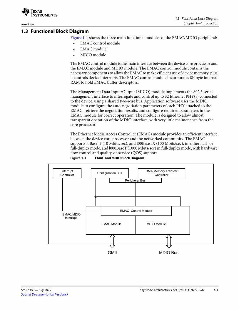
1.3 Functional Block Diagram
SPRUHH1—July 2012 KeyStone Architecture EMAC/MDIO User Guide 1-3Submit Documentation Feedback
Chapter 1—Introductionwww.ti.com
1.3 Functional Block DiagramFigure 1-1 shows the three main functional modules of the EMAC/MDIO peripheral:
• EMAC control module • EMAC module • MDIO module
The EMAC control module is the main interface between the device core processor and the EMAC module and MDIO module. The EMAC control module contains the necessary components to allow the EMAC to make efficient use of device memory, plus it controls device interrupts. The EMAC control module incorporates 8K byte internal RAM to hold EMAC buffer descriptors.
The Management Data Input/Output (MDIO) module implements the 802.3 serial management interface to interrogate and control up to 32 Ethernet PHY(s) connected to the device, using a shared two-wire bus. Application software uses the MDIO module to configure the auto-negotiation parameters of each PHY attached to the EMAC, retrieve the negotiation results, and configure required parameters in the EMAC module for correct operation. The module is designed to allow almost transparent operation of the MDIO interface, with very little maintenance from the core processor.
The Ethernet Media Access Controller (EMAC) module provides an efficient interface between the device core processor and the networked community. The EMAC supports l0Base-T (10 Mbits/sec), and l00BaseTX (100 Mbits/sec), in either half- or full-duplex mode, and l000BaseT (1000 Mbits/sec) in full-duplex mode, with hardware flow control and quality-of-service (QOS) support. Figure 1-1 EMAC and MDIO Block Diagram
Interrupt
ControllerConfiguration Bus
DMA Memory Transfer
Controller
Peripheral Bus
EMAC Module MDIO Module
EMAC/MDIOInterrupt
GMII MDIO Bus
EMAC Control Module
1.4 Industry Standard(s) Compliance Statement
1-4 KeyStone Architecture EMAC/MDIO User Guide SPRUHH1—July 2012Submit Documentation Feedback
Chapter 1—Introduction www.ti.com
Figure 1-1 shows the main interface between the EMAC control module and the CPU. The following connections are made to the device core:
• The peripheral bus connection from the EMAC control module allows the EMAC module to read and write both internal and external memory through the switch fabric interface.
• The EMAC control, EMAC, and MDIO modules all have control registers. These registers are memory mapped into device memory space via the device configuration bus. The control module internal RAM is mapped to this same range along with these registers.
• The EMAC and MDIO interrupts are combined within the control module. The interrupts from the control module then go to the device interrupt controller.
The EMAC and MDIO interrupts are combined within the control module, so only the control module interrupts need to be monitored by the application software or device driver. The interrupts are mapped to a specific DSP interrupt through the use of the C66x CorePac Interrupt Controller.
1.4 Industry Standard(s) Compliance StatementThe EMAC peripheral conforms to the IEEE 802.3 standard, describing the Carrier Sense Multiple Access with Collision Detection (CSMNCD) Access Method and Physical Layer specifications. The IEEE 802.3 standard has also been adopted by ISO/IEC and re-designated as ISO/IEC 8802-3:2000(E).
In difference from this standard, the EMAC peripheral integrated with the device does not use the transmit coding error signal MTXER. Instead of driving the error pin when an underflow condition occurs on a transmitted frame, the EMAC intentionally generates an incorrect checksum by inverting the frame CRC, so that the transmitted frame will be detected as an error by the network.
SPRUHH1—July 2012 KeyStone Architecture EMAC/MDIO User Guide 2-1Submit Documentation Feedback
Chapter 2
EMAC Functional Architecture
This section discusses the architecture and basic function of the EMAC peripheral.
2.1 "Clock Control" on page 2-2 2.2 "Memory Map" on page 2-3 2.3 "System Level Connection" on page 2-4 2.4 "Ethernet Protocol Overview" on page 2-6 2.5 "Programming Interface" on page 2-8 2.6 "EMAC Control Module" on page 2-19 2.7 "Management Data Input/Output (MDIO) Module" on page 2-22 2.8 "EMAC Module" on page 2-27 2.9 "Media Independent Interfaces" on page 2-31
2.10 "Packet Receive Operation" on page 2-36 2.11 "Packet Transmit Operation" on page 2-42 2.12 "Receive and Transmit Latency" on page 2-43 2.13 "Transfer Node Priority" on page 2-44 2.14 "Reset Considerations" on page 2-45 2.15 "Initialization" on page 2-46 2.16 "Interrupt Support" on page 2-49 2.17 "Pulse Interrupts" on page 2-53 2.18 "SGMII Interface" on page 2-54 2.19 "SERDES Macro and Configurations" on page 2-56 2.20 "MAC Address" on page 2-59 2.21 "Power Management" on page 2-60 2.22 "Emulation Considerations" on page 2-61
2.1 Clock Control
2-2 KeyStone Architecture EMAC/MDIO User Guide SPRUHH1—July 2012Submit Documentation Feedback
Chapter 2—EMAC Functional Architecture www.ti.com
2.1 Clock ControlThe frequencies for the transmit and receive clocks are fixed by the IEEE 802.3 specification as shown below:
• 2.5 MHz at 10 Mbps• 25 MHz at 100 Mbps• 125 MHz at 1000 Mbps
SYSCLK7 is used as the clock for the EMAC logic on the device. SYSCLK7 is generated from the main PLL controller, and runs at a rate equal to one-sixth of the DSP clock frequency (DSPCLK/6).
The MDIO clock is based on a divide-down of SYSCLK7, and is specified to run up to 2.5 MHz, although typical operation would be 1.0 MHz, as the peripheral clock frequency is variable, the application software or driver controls the divide-down amount.
2.1.1 GMII ClockingThe transmit and receive clock sources for 10/100/1000 Mbps modes are provided from an external PHY via GMII_MTCLK and GMII_MRCLK pins.
2.1.2 SGMII ClockingThe SGMII module uses clocks from two different sources: one is sourced from SYSCLK7 and the other is sourced from the MTCLK/MRCLK. SYSCLK7 is sourced from the main PLL controller, and operates at DSPCLK/6. The SGMII logic derives its operating clocks from the SerDes output, so the SGMII SerDes must be configured before the interface can be used.
The SGMII protocol takes a GMII data stream and converts it to a serial stream using the SerDes macro, sending the same amount of data with an embedded clock (using 8b/10b). The SGMII protocol also allows for dynamic switching between 10/100/1000 Mbps modes. This negotiation data is embedded in the incoming data stream from the external PHY and can happen at any time. Since the SGMII logic only supports the protocol with an embedded clock, 10/100 Mbps rates are supported by duplicating the data across multiple data phases (modified by 8b/10b at the physical interface), allowing the SGMII module to keep the same data on the pins for the slower rates to the CPGMAC module.
2.1.3 SGMII SerDes ClockingThe SGMII SerDes reference clock is an input to the DSP. The SGMII SerDes reference clock serves as the input to the SGMII SerDes PLL, which is configured through the SGMII_SERDES_CFG_PLL chip-level register. The output from the SGMII SerDes PLL controls the link rate, and requires a dedicated clock input of 156.25, 250, or 312.5 MHz.
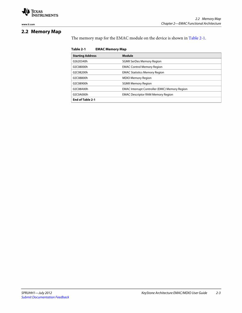
2.2 Memory Map
SPRUHH1—July 2012 KeyStone Architecture EMAC/MDIO User Guide 2-3Submit Documentation Feedback
Chapter 2—EMAC Functional Architecturewww.ti.com
2.2 Memory MapThe memory map for the EMAC module on the device is shown in Table 2-1.
Table 2-1 EMAC Memory Map
Starting Address Module
02620340h SGMII SerDes Memory Region
02C08000h EMAC Control Memory Region
02C08200h EMAC Statistics Memory Region
02C08800h MDIO Memory Region
02C08900h SGMII Memory Region
02C08A00h EMAC Interrupt Controller (EMIC) Memory Region
02C0A000h EMAC Descriptor RAM Memory Region
End of Table 2-1
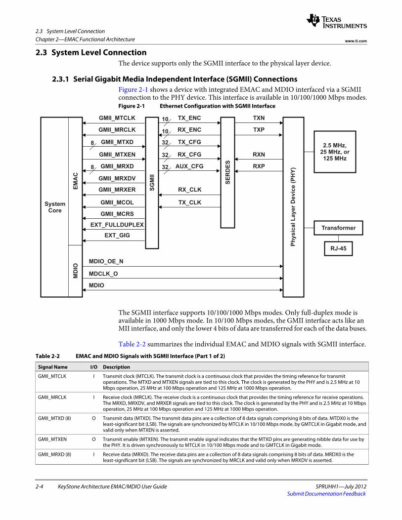
2.3 System Level Connection
2-4 KeyStone Architecture EMAC/MDIO User Guide SPRUHH1—July 2012Submit Documentation Feedback
Chapter 2—EMAC Functional Architecture www.ti.com
2.3 System Level ConnectionThe device supports only the SGMII interface to the physical layer device.
2.3.1 Serial Gigabit Media Independent Interface (SGMII) ConnectionsFigure 2-1 shows a device with integrated EMAC and MDIO interfaced via a SGMII connection to the PHY device. This interface is available in 10/100/1000 Mbps modes.Figure 2-1 Ethernet Configuration with SGMII Interface
The SGMII interface supports 10/100/1000 Mbps modes. Only full-duplex mode is available in 1000 Mbps mode. In 10/100 Mbps modes, the GMII interface acts like an MII interface, and only the lower 4 bits of data are transferred for each of the data buses.
Table 2-2 summarizes the individual EMAC and MDIO signals with SGMII interface.
GMII_MTCLK
GMII_MRCLK
GMII_MTXD
GMII_MTXEN
GMII_MRXD
GMII_MRXDV
8
8
GMII_MRXER
GMII_MCOL
GMII_MCRS
EXT_FULLDUPLEX
EXT_GIG
MDIO_OE_N
MDCLK_O
MDIO
10
10
32
32
32
TX_ENC
RX_ENC
TX_CFG
RX_CFG
AUX_CFG
RX_CLK
TX_CLK
TXN
TXP
RXN
RXP
2.5 MHz,25 MHz, or125 MHz
Transformer
RJ-45
MD
IOE
MA
C
SG
MII
SE
RD
ES
Ph
ys
ica
lL
ay
er
De
vic
e(P
HY
)
SystemCore
Table 2-2 EMAC and MDIO Signals with SGMII Interface (Part 1 of 2)
Signal Name I/O Description
GMII_MTCLK I Transmit clock (MTCLK). The transmit clock is a continuous clock that provides the timing reference for transmit operations. The MTXD and MTXEN signals are tied to this clock. The clock is generated by the PHY and is 2.5 MHz at 10 Mbps operation, 25 MHz at 100 Mbps operation and 125 MHz at 1000 Mbps operation.
GMII_MRCLK I Receive clock (MRCLK). The receive clock is a continuous clock that provides the timing reference for receive operations. The MRXD, MRXDV, and MRXER signals are tied to this clock. The clock is generated by the PHY and is 2.5 MHz at 10 Mbps operation, 25 MHz at 100 Mbps operation and 125 MHz at 1000 Mbps operation.
GMII_MTXD (8) O Transmit data (MTXD). The transmit data pins are a collection of 8 data signals comprising 8 bits of data. MTDX0 is the least-significant bit (LSB). The signals are synchronized by MTCLK in 10/100 Mbps mode, by GMTCLK in Gigabit mode, and valid only when MTXEN is asserted.
GMII_MTXEN O Transmit enable (MTXEN). The transmit enable signal indicates that the MTXD pins are generating nibble data for use by the PHY. It is driven synchronously to MTCLK in 10/100 Mbps mode and to GMTCLK in Gigabit mode.
GMII_MRXD (8) I Receive data (MRXD). The receive data pins are a collection of 8 data signals comprising 8 bits of data. MRDX0 is the least-significant bit (LSB). The signals are synchronized by MRCLK and valid only when MRXDV is asserted.
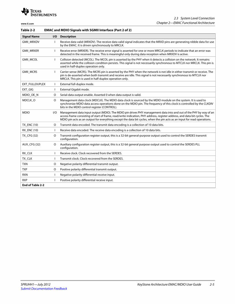
2.3 System Level Connection
SPRUHH1—July 2012 KeyStone Architecture EMAC/MDIO User Guide 2-5Submit Documentation Feedback
Chapter 2—EMAC Functional Architecturewww.ti.com
GMII_MRXDV I Receive data valid (MRXDV). The receive data valid signal indicates that the MRXD pins are generating nibble data for use by the EMAC. It is driven synchronously to MRCLK.
GMII_MRXER I Receive error (MRXER). The receive error signal is asserted for one or more MRCLK periods to indicate that an error was detected in the received frame. This is meaningful only during data reception when MRXDV is active.
GMII_MCOL I Collision detected (MCOL). The MCOL pin is asserted by the PHY when it detects a collision on the network. It remains asserted while the collision condition persists. This signal is not necessarily synchronous to MTCLK nor MRCLK. This pin is used in half-duplex operation only.
GMII_MCRS I Carrier sense (MCRS). The MCRS pin is asserted by the PHY when the network is not idle in either transmit or receive. The pin is de-asserted when both transmit and receive are idle. This signal is not necessarily synchronous to MTCLK nor MRCLK. This pin is used in half-duplex operation only.
EXT_FULLDUPLEX I External full-duplex mode.
EXT_GIG I External Gigabit mode.
MDIO_OE_N O Serial-data output enable. Asserted 0 when data output is valid.
MDCLK_O O Management data clock (MDCLK). The MDIO data clock is sourced by the MDIO module on the system. It is used to synchronize MDIO data access operations done on the MDIO pin. The frequency of this clock is controlled by the CLKDIV bits in the MDIO control register (CONTROL).
MDIO I/O Management data input output (MDIO). The MDIO pin drives PHY management data into and out of the PHY by way of an access frame consisting of start of frame, read/write indication, PHY address, register address, and data bit cycles. The MDIO pin acts as an output for everything except the data bit cycles, when the pin acts as an input for read operations.
TX_ENC (10) O Transmit data encoded. The transmit data encoding is a collection of 10 data bits.
RX_ENC (10) I Receive data encoded. The receive data encoding is a collection of 10 data bits.
TX_CFG (32) O Transmit configuration register output, this is a 32-bit general-purpose output used to control the SERDES transmit configuration.
AUX_CFG (32) O Auxiliary configuration register output, this is a 32-bit general purpose output used to control the SERDES PLL configuration.
RX_CLK I Receive clock. Clock recovered from the SERDES.
TX_CLK I Transmit clock. Clock recovered from the SERDES.
TXN O Negative polarity differential transmit output.
TXP O Positive polarity differential transmit output.
RXN I Negative polarity differential receive input.
RXP I Positive polarity differential receive input.
End of Table 2-2
Table 2-2 EMAC and MDIO Signals with SGMII Interface (Part 2 of 2)
Signal Name I/O Description
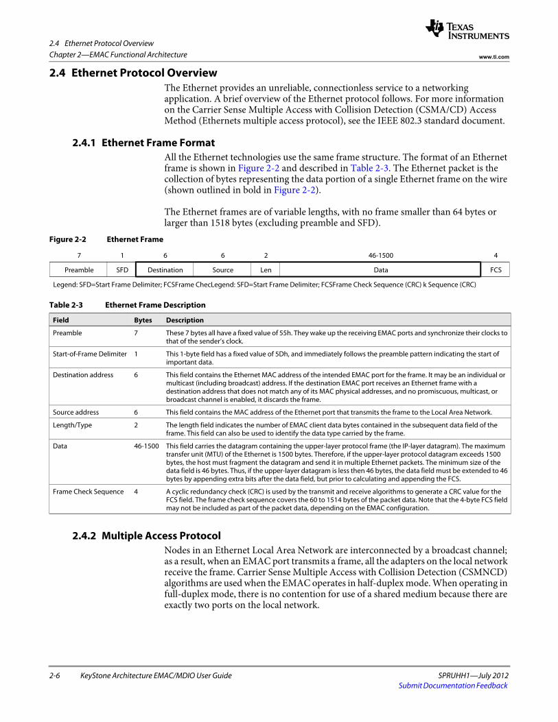
2.4 Ethernet Protocol Overview
2-6 KeyStone Architecture EMAC/MDIO User Guide SPRUHH1—July 2012Submit Documentation Feedback
Chapter 2—EMAC Functional Architecture www.ti.com
2.4 Ethernet Protocol OverviewThe Ethernet provides an unreliable, connectionless service to a networking application. A brief overview of the Ethernet protocol follows. For more information on the Carrier Sense Multiple Access with Collision Detection (CSMA/CD) Access Method (Ethernets multiple access protocol), see the IEEE 802.3 standard document.
2.4.1 Ethernet Frame FormatAll the Ethernet technologies use the same frame structure. The format of an Ethernet frame is shown in Figure 2-2 and described in Table 2-3. The Ethernet packet is the collection of bytes representing the data portion of a single Ethernet frame on the wire (shown outlined in bold in Figure 2-2).
The Ethernet frames are of variable lengths, with no frame smaller than 64 bytes or larger than 1518 bytes (excluding preamble and SFD).
2.4.2 Multiple Access ProtocolNodes in an Ethernet Local Area Network are interconnected by a broadcast channel; as a result, when an EMAC port transmits a frame, all the adapters on the local network receive the frame. Carrier Sense Multiple Access with Collision Detection (CSMNCD) algorithms are used when the EMAC operates in half-duplex mode. When operating in full-duplex mode, there is no contention for use of a shared medium because there are exactly two ports on the local network.
Figure 2-2 Ethernet Frame
7 1 6 6 2 46-1500 4
Preamble SFD Destination Source Len Data FCS
Legend: SFD=Start Frame Delimiter; FCSFrame ChecLegend: SFD=Start Frame Delimiter; FCSFrame Check Sequence (CRC) k Sequence (CRC)
Table 2-3 Ethernet Frame Description
Field Bytes Description
Preamble 7 These 7 bytes all have a fixed value of 55h. They wake up the receiving EMAC ports and synchronize their clocks to that of the sender’s clock.
Start-of-Frame Delimiter 1 This 1-byte field has a fixed value of 5Dh, and immediately follows the preamble pattern indicating the start of important data.
Destination address 6 This field contains the Ethernet MAC address of the intended EMAC port for the frame. It may be an individual or multicast (including broadcast) address. If the destination EMAC port receives an Ethernet frame with a destination address that does not match any of its MAC physical addresses, and no promiscuous, multicast, or broadcast channel is enabled, it discards the frame.
Source address 6 This field contains the MAC address of the Ethernet port that transmits the frame to the Local Area Network.
Length/Type 2 The length field indicates the number of EMAC client data bytes contained in the subsequent data field of the frame. This field can also be used to identify the data type carried by the frame.
Data 46-1500 This field carries the datagram containing the upper-layer protocol frame (the IP-layer datagram). The maximum transfer unit (MTU) of the Ethernet is 1500 bytes. Therefore, if the upper-layer protocol datagram exceeds 1500 bytes, the host must fragment the datagram and send it in multiple Ethernet packets. The minimum size of the data field is 46 bytes. Thus, if the upper-layer datagram is less then 46 bytes, the data field must be extended to 46 bytes by appending extra bits after the data field, but prior to calculating and appending the FCS.
Frame Check Sequence 4 A cyclic redundancy check (CRC) is used by the transmit and receive algorithms to generate a CRC value for the FCS field. The frame check sequence covers the 60 to 1514 bytes of the packet data. Note that the 4-byte FCS field may not be included as part of the packet data, depending on the EMAC configuration.
2.4 Ethernet Protocol Overview
SPRUHH1—July 2012 KeyStone Architecture EMAC/MDIO User Guide 2-7Submit Documentation Feedback
Chapter 2—EMAC Functional Architecturewww.ti.com
Each port runs the CSMA/CD protocol without explicit coordination with the other ports on the Ethernet network. Within a specific port, the CSMA/CD protocol is as follows:
1. The port obtains data from upper-layer protocols at its node, prepares an Ethernet frame, and puts the frame in a buffer.
2. If the port senses that the medium is idle, it starts to transmit the frame. If the port senses that the transmission medium is busy, it waits until it senses no signal energy (plus an inter-packet gap time) and then starts to transmit the frame.
3. While transmitting, the port monitors for the presence of signal energy coming from other ports. If the port transmits the entire frame without detecting signal energy from other Ethernet devices, the port is done with the frame.
4. If the port detects signal energy from other ports while transmitting, it stops transmitting its frame and instead transmits a 48-bit jam signal.
5. After transmitting the jam signal, the port enters an exponential back-off phase. Specifically, when transmitting a given frame, after experiencing a number of collisions in a row for the frame, the port chooses a random value that is dependent on the number of collisions. The port then waits an amount of time, that is a multiple of this random value, and returns to Step 2.
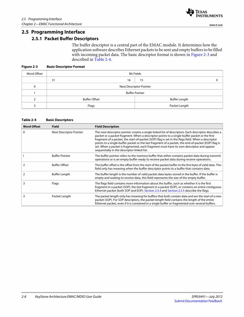
2.5 Programming Interface
2-8 KeyStone Architecture EMAC/MDIO User Guide SPRUHH1—July 2012Submit Documentation Feedback
Chapter 2—EMAC Functional Architecture www.ti.com
2.5 Programming Interface2.5.1 Packet Buffer Descriptors
The buffer descriptor is a central part of the EMAC module. It determines how the application software describes Ethernet packets to be sent and empty buffers to be filled with incoming packet data. The basic descriptor format is shown in Figure 2-3 and described in Table 2-4.
Figure 2-3 Basic Descriptor Format
Word Offset Bit Fields
31 16 15 0
0 Next Descriptor Pointer
1 Buffer Pointer
2 Buffer Offset Buffer Length
3 Flags Packet Length
Table 2-4 Basic Descriptors
Word Offset Field Field Description
0 Next Descriptor Pointer The next descriptor pointer creates a single linked list of descriptors. Each descriptor describes a packet or a packet fragment. When a descriptor points to a single-buffer packet or the first fragment of a packet, the start-of-packet (SOP) flag is set in the flags field. When a descriptor points to a single-buffer packet or the last fragment of a packet, the end-of-packet (EOP) flag is set. When a packet is fragmented, each fragment must have its own descriptor and appear sequentially in the descriptor linked list.
I Buffer Pointer The buffer pointer refers to the memory buffer that either contains packet data during transmit operations or is an empty buffer ready to receive packet data during receive operations.
2 Buffer Offset The buffer offset is the offset from the start of the packet buffer to the first byte of valid data. This field only has meaning when the buffer descriptor points to a buffer that contains data.
2 Buffer Length The buffer length is the number of valid packet data bytes stored in the buffer. If the buffer is empty and waiting to receive data, this field represents the size of the empty buffer.
3 Flags The flags field contains more information about the buffer, such as whether it is the first fragment in a packet (SOP), the last fragment in a packet (EOP), or contains an entire contiguous Ethernet packet (both SOP and EOP). Section 2.5.4 and Section 2.5.5 describe the flags.
3 Packet Length The packet length only has meaning for buffers that both contain data and are the start of a new packet (SOP). For SOP descriptors, the packet length field contains the length of the entire Ethernet packet, even if it is contained in a single buffer or fragmented over several buffers.
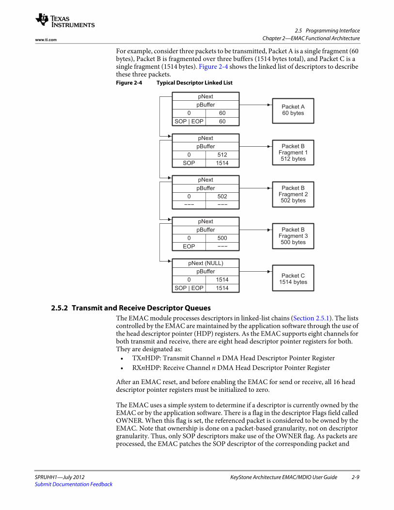
2.5 Programming Interface
SPRUHH1—July 2012 KeyStone Architecture EMAC/MDIO User Guide 2-9Submit Documentation Feedback
Chapter 2—EMAC Functional Architecturewww.ti.com
For example, consider three packets to be transmitted, Packet A is a single fragment (60 bytes), Packet B is fragmented over three buffers (1514 bytes total), and Packet C is a single fragment (1514 bytes). Figure 2-4 shows the linked list of descriptors to describe these three packets.Figure 2-4 Typical Descriptor Linked List
2.5.2 Transmit and Receive Descriptor QueuesThe EMAC module processes descriptors in linked-list chains (Section 2.5.1). The lists controlled by the EMAC are maintained by the application software through the use of the head descriptor pointer (HDP) registers. As the EMAC supports eight channels for both transmit and receive, there are eight head descriptor pointer registers for both. They are designated as:
• TXnHDP: Transmit Channel n DMA Head Descriptor Pointer Register • RXnHDP: Receive Channel n DMA Head Descriptor Pointer Register
After an EMAC reset, and before enabling the EMAC for send or receive, all 16 head descriptor pointer registers must be initialized to zero.
The EMAC uses a simple system to determine if a descriptor is currently owned by the EMAC or by the application software. There is a flag in the descriptor Flags field called OWNER. When this flag is set, the referenced packet is considered to be owned by the EMAC. Note that ownership is done on a packet-based granularity, not on descriptor granularity. Thus, only SOP descriptors make use of the OWNER flag. As packets are processed, the EMAC patches the SOP descriptor of the corresponding packet and
SOP | EOP 600 60
pBufferpNext
Packet A60 bytes
0SOP
Fragment 1Packet B
5121514
pBufferpNext
512 bytes
EOP0
0−−−
Packet BFragment 3500 bytes
502
pBuffer
−−−500
pNext
−−−
pBufferpNext
Packet BFragment 2502 bytes
SOP | EOP0 1514 bytes
Packet C
1514
pBufferpNext (NULL)
1514
2.5 Programming Interface
2-10 KeyStone Architecture EMAC/MDIO User Guide SPRUHH1—July 2012Submit Documentation Feedback
Chapter 2—EMAC Functional Architecture www.ti.com
clears the OWNER flag. This is an indication that the EMAC has finished processing all descriptors up to and including the first with the EOP flag set indicating the end of the packet. Note that this may only be one descriptor with both the SOP and EOP flags set.
To add a descriptor or a linked list of descriptors to an EMAC descriptor queue for the first time, the software application writes the pointer to the descriptor or first descriptor of a list to the corresponding HDP register. Note that the last descriptor in the list must have its next pointer cleared so that the EMAC can detect the end of the list. If only a single descriptor is added, its next descriptor pointer must be initialized to zero.
The HDP register must never be written to a second time while a previous list is active. To add additional descriptors to a descriptor list already owned by the EMAC, the NULL next pointer of the last descriptor of the previous list is patched with a pointer to the first descriptor in the new list. The list of new descriptors to be appended to the existing list must itself be NULL terminated before the pointer patch is performed.
If the EMAC reads the next pointer of a descriptor as NULL in the instant before an application appends additional descriptors to the list by patching the pointer, this may result in a race condition. Thus, the software application must always examine the Flags field of all EOP packets, looking for a special flag called the end-of-queue (EOQ) flag. The EOQ flag is set by the EMAC on the last descriptor of a packet when the descriptors next pointer is NULL, allowing the EMAC to indicate to the software application that it has reached the end of the list. When the software application sees the EOQ flag set, and there are more descriptors to process, the application may then submit the new list or missed list portion by writing the new list pointer to the same HDP register that started the process.
This process applies when adding packets to a transmit list and empty buffers to a receive list.
2.5.3 Transmit and Receive EMAC InterruptsThe EMAC processes descriptors in linked-list chains (Section 2.5.1), using the linked-list queue mechanism (Section 2.5.2).
The EMAC synchronizes the descriptor list processing by using interrupts to the software application. The interrupts are controlled by the application by using the interrupt masks, global interrupt enable, and the completion pointer register (CP). This register is also called interrupt acknowledge register.
As the EMAC supports eight channels for both transmit and receive, there are eight completion pointer registers for transmit and eight completion pointers for receive. They are designated as:
• TXnCP: Transmit Channel n Completion Pointer (Interrupt Acknowledge) Register
• RXnCP: Receive Channel n Completion Pointer (Interrupt Acknowledge) Register
These registers serve two purposes. When read, they return the pointer to the last descriptor that the EMAC has processed. When written by the software application, the value represents the last descriptor processed by the software application. If these two values do not match, the interrupt is active.
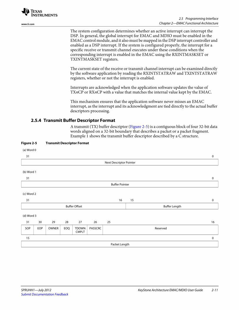
2.5 Programming Interface
SPRUHH1—July 2012 KeyStone Architecture EMAC/MDIO User Guide 2-11Submit Documentation Feedback
Chapter 2—EMAC Functional Architecturewww.ti.com
The system configuration determines whether an active interrupt can interrupt the DSP. In general, the global interrupt for EMAC and MDIO must be enabled in the EMAC control module, and it also must be mapped in the DSP interrupt controller and enabled as a DSP interrupt. If the system is configured properly, the interrupt for a specific receive or transmit channel executes under these conditions when the corresponding interrupt is enabled in the EMAC using the RXINTMASKSET or TXINTMASKSET registers.
The current state of the receive or transmit channel interrupt can be examined directly by the software application by reading the RXINTSTATRAW and TXINTSTATRAW registers, whether or not the interrupt is enabled.
Interrupts are acknowledged when the application software updates the value of TXnCP or RXnCP with a value that matches the internal value kept by the EMAC.
This mechanism ensures that the application software never misses an EMAC interrupt, as the interrupt and its acknowledgment are tied directly to the actual buffer descriptors processing.
2.5.4 Transmit Buffer Descriptor FormatA transmit (TX) buffer descriptor (Figure 2-5) is a contiguous block of four 32-bit data words aligned on a 32-bit boundary that describes a packet or a packet fragment. Example 1 shows the transmit buffer descriptor described by a C structure.
Figure 2-5 Transmit Descriptor Format
(a) Word 0
31 0
Next Descriptor Pointerspacer
(b) Word 1
31 0
Buffer Pointerspacer
(c) Word 2
31 16 15 0
Buffer Offset Buffer Lengthspacer
(d) Word 3
31 30 29 28 27 26 25 16
SOP EOP OWNER EOQ TDOWN CMPLT
PASSCRC Reserved
15 0
Packet Lengthspacer
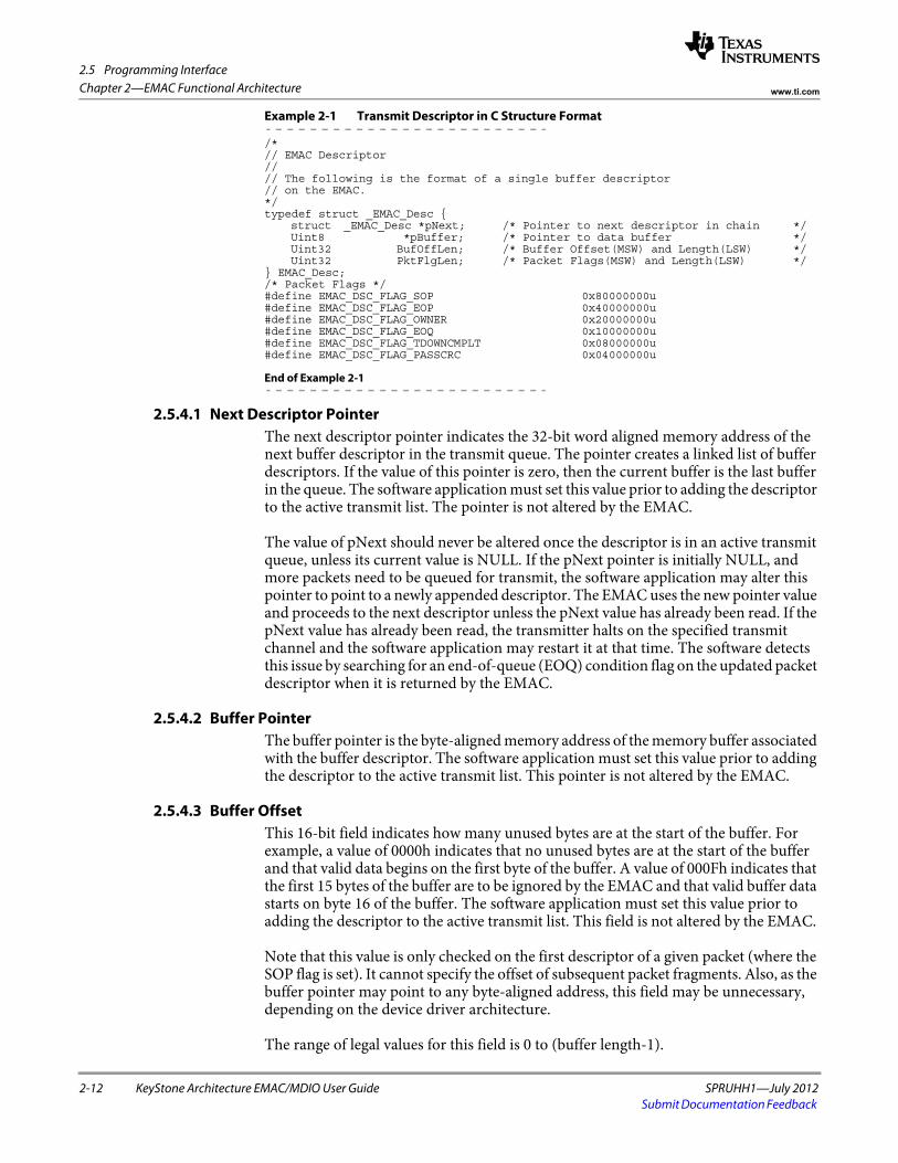
2.5 Programming Interface
2-12 KeyStone Architecture EMAC/MDIO User Guide SPRUHH1—July 2012Submit Documentation Feedback
Chapter 2—EMAC Functional Architecture www.ti.com
Example 2-1 Transmit Descriptor in C Structure Format
/*// EMAC Descriptor//// The following is the format of a single buffer descriptor// on the EMAC.*/typedef struct _EMAC_Desc {
struct _EMAC_Desc *pNext; /* Pointer to next descriptor in chain */Uint8 *pBuffer; /* Pointer to data buffer */Uint32 BufOffLen; /* Buffer Offset(MSW) and Length(LSW) */Uint32 PktFlgLen; /* Packet Flags(MSW) and Length(LSW) */
} EMAC_Desc;/* Packet Flags */#define EMAC_DSC_FLAG_SOP 0x80000000u#define EMAC_DSC_FLAG_EOP 0x40000000u#define EMAC_DSC_FLAG_OWNER 0x20000000u#define EMAC_DSC_FLAG_EOQ 0x10000000u#define EMAC_DSC_FLAG_TDOWNCMPLT 0x08000000u#define EMAC_DSC_FLAG_PASSCRC 0x04000000u
End of Example 2-1
2.5.4.1 Next Descriptor PointerThe next descriptor pointer indicates the 32-bit word aligned memory address of the next buffer descriptor in the transmit queue. The pointer creates a linked list of buffer descriptors. If the value of this pointer is zero, then the current buffer is the last buffer in the queue. The software application must set this value prior to adding the descriptor to the active transmit list. The pointer is not altered by the EMAC.
The value of pNext should never be altered once the descriptor is in an active transmit queue, unless its current value is NULL. If the pNext pointer is initially NULL, and more packets need to be queued for transmit, the software application may alter this pointer to point to a newly appended descriptor. The EMAC uses the new pointer value and proceeds to the next descriptor unless the pNext value has already been read. If the pNext value has already been read, the transmitter halts on the specified transmit channel and the software application may restart it at that time. The software detects this issue by searching for an end-of-queue (EOQ) condition flag on the updated packet descriptor when it is returned by the EMAC.
2.5.4.2 Buffer PointerThe buffer pointer is the byte-aligned memory address of the memory buffer associated with the buffer descriptor. The software application must set this value prior to adding the descriptor to the active transmit list. This pointer is not altered by the EMAC.
2.5.4.3 Buffer OffsetThis 16-bit field indicates how many unused bytes are at the start of the buffer. For example, a value of 0000h indicates that no unused bytes are at the start of the buffer and that valid data begins on the first byte of the buffer. A value of 000Fh indicates that the first 15 bytes of the buffer are to be ignored by the EMAC and that valid buffer data starts on byte 16 of the buffer. The software application must set this value prior to adding the descriptor to the active transmit list. This field is not altered by the EMAC.
Note that this value is only checked on the first descriptor of a given packet (where the SOP flag is set). It cannot specify the offset of subsequent packet fragments. Also, as the buffer pointer may point to any byte-aligned address, this field may be unnecessary, depending on the device driver architecture.
The range of legal values for this field is 0 to (buffer length-1).
2.5 Programming Interface
SPRUHH1—July 2012 KeyStone Architecture EMAC/MDIO User Guide 2-13Submit Documentation Feedback
Chapter 2—EMAC Functional Architecturewww.ti.com
2.5.4.4 Buffer LengthThis 16-bit field indicates how many valid data bytes are in the buffer. On single-fragment packets, this value is also the total length of the packet data to be transmitted. If the buffer offset field is used, the offset bytes are not counted as part of this length. This length counts only valid data bytes. The software application must set this value prior to adding the descriptor to the active transmit list. This field is not altered by the EMAC.
2.5.4.5 Packet LengthThis 16-bit field specifies the number of data bytes in the entire packet. Any leading buffer offset bytes are not included. The sum of the buffer length fields of each of the packets fragments (if more than one) must be equal to the packet length. The software application must set this value prior to adding the descriptor to the active transmit list. This field is not altered by the EMAC. This value is only checked on the first descriptor of a given packet, where the SOP flag is set.
2.5.4.6 Start-of-Packet (SOP) FlagWhen set, this flag indicates that the descriptor points to a packet buffer that is the start of a new packet. For a single-fragment packet, both the SOP and end-of-packet (EOP) flags are set. Otherwise, the descriptor pointing to the last packet buffer for the packet sets the EOP flag. This bit is set by the software application and is not altered by the EMAC.
2.5.4.7 End-of-Packet (EOP) FlagWhen set, this flag indicates that the descriptor points to the last packet buffer for a given packet. For a single-fragment packet, both the start-of-packet (SOP) and EOP flags are set. Otherwise, the descriptor pointing to the last packet buffer for the packet sets the EOP flag. This bit is set by the software application and is not altered by the EMAC.
2.5.4.8 Ownership (OWNER) FlagWhen set, this flag indicates that all the descriptors for the given packet (from SOP to EOP) are currently owned by the EMAC. This flag is set by the software application on the SOP packet descriptor before adding the descriptor to the transmit descriptor queue. For a single-fragment packet, the SOP, EOP, and OWNER flags are all set. The OWNER flag is cleared by the EMAC once it is finished with all the descriptors for the given packet. Note that this flag is valid on SOP descriptors only.
2.5.4.9 End-of-Queue (EOQ) flagWhen set, this flag indicates that the descriptor in question was the last descriptor in the transmit queue for a given transmit channel and that the transmitter has halted. This flag is initially cleared by the software application prior to adding the descriptor to the transmit queue. This bit is set by the EMAC when the EMAC identifies that a descriptor is the last for a given packet (the EOP flag is set) and there are no more descriptors in the transmit list (next descriptor pointer is NULL).
The software application can use this bit to detect when the EMAC transmitter for the corresponding channel has halted. This is useful when the application appends additional packet descriptors to a transmit queue list that is already owned by the EMAC. Note that this flag is valid on EOP descriptors only.
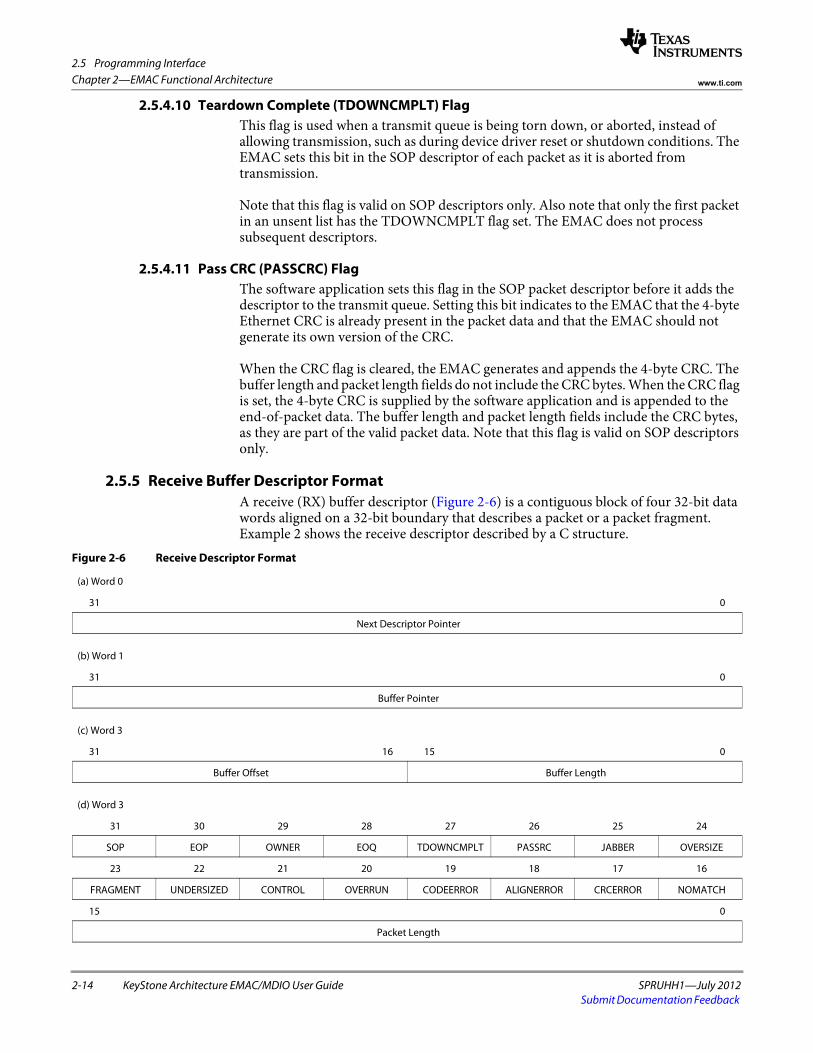
2.5 Programming Interface
2-14 KeyStone Architecture EMAC/MDIO User Guide SPRUHH1—July 2012Submit Documentation Feedback
Chapter 2—EMAC Functional Architecture www.ti.com
2.5.4.10 Teardown Complete (TDOWNCMPLT) FlagThis flag is used when a transmit queue is being torn down, or aborted, instead of allowing transmission, such as during device driver reset or shutdown conditions. The EMAC sets this bit in the SOP descriptor of each packet as it is aborted from transmission.
Note that this flag is valid on SOP descriptors only. Also note that only the first packet in an unsent list has the TDOWNCMPLT flag set. The EMAC does not process subsequent descriptors.
2.5.4.11 Pass CRC (PASSCRC) FlagThe software application sets this flag in the SOP packet descriptor before it adds the descriptor to the transmit queue. Setting this bit indicates to the EMAC that the 4-byte Ethernet CRC is already present in the packet data and that the EMAC should not generate its own version of the CRC.
When the CRC flag is cleared, the EMAC generates and appends the 4-byte CRC. The buffer length and packet length fields do not include the CRC bytes. When the CRC flag is set, the 4-byte CRC is supplied by the software application and is appended to the end-of-packet data. The buffer length and packet length fields include the CRC bytes, as they are part of the valid packet data. Note that this flag is valid on SOP descriptors only.
2.5.5 Receive Buffer Descriptor FormatA receive (RX) buffer descriptor (Figure 2-6) is a contiguous block of four 32-bit data words aligned on a 32-bit boundary that describes a packet or a packet fragment. Example 2 shows the receive descriptor described by a C structure.
Figure 2-6 Receive Descriptor Format
(a) Word 0
31 0
Next Descriptor Pointerspacer
(b) Word 1
31 0
Buffer Pointerspacer
(c) Word 3
31 16 15 0
Buffer Offset Buffer Lengthspacer
(d) Word 3
31 30 29 28 27 26 25 24
SOP EOP OWNER EOQ TDOWNCMPLT PASSRC JABBER OVERSIZE
23 22 21 20 19 18 17 16
FRAGMENT UNDERSIZED CONTROL OVERRUN CODEERROR ALIGNERROR CRCERROR NOMATCH
15 0
Packet Lengthspacer
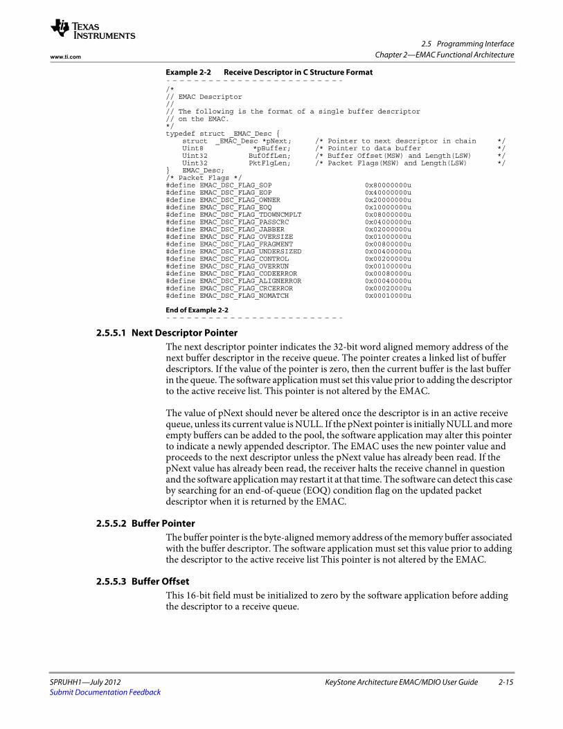
2.5 Programming Interface
SPRUHH1—July 2012 KeyStone Architecture EMAC/MDIO User Guide 2-15Submit Documentation Feedback
Chapter 2—EMAC Functional Architecturewww.ti.com
Example 2-2 Receive Descriptor in C Structure Format
/*// EMAC Descriptor//// The following is the format of a single buffer descriptor// on the EMAC.*/typedef struct _EMAC_Desc {
struct _EMAC_Desc *pNext; /* Pointer to next descriptor in chain */Uint8 *pBuffer; /* Pointer to data buffer */Uint32 BufOffLen; /* Buffer Offset(MSW) and Length(LSW) */Uint32 PktFlgLen; /* Packet Flags(MSW) and Length(LSW) */
} EMAC_Desc;/* Packet Flags */#define EMAC_DSC_FLAG_SOP 0x80000000u#define EMAC_DSC_FLAG_EOP 0x40000000u#define EMAC_DSC_FLAG_OWNER 0x20000000u#define EMAC_DSC_FLAG_EOQ 0x10000000u#define EMAC_DSC_FLAG_TDOWNCMPLT 0x08000000u#define EMAC_DSC_FLAG_PASSCRC 0x04000000u#define EMAC_DSC_FLAG_JABBER 0x02000000u#define EMAC_DSC_FLAG_OVERSIZE 0x01000000u#define EMAC_DSC_FLAG_FRAGMENT 0x00800000u#define EMAC_DSC_FLAG_UNDERSIZED 0x00400000u#define EMAC_DSC_FLAG_CONTROL 0x00200000u#define EMAC_DSC_FLAG_OVERRUN 0x00100000u#define EMAC_DSC_FLAG_CODEERROR 0x00080000u#define EMAC_DSC_FLAG_ALIGNERROR 0x00040000u#define EMAC_DSC_FLAG_CRCERROR 0x00020000u#define EMAC_DSC_FLAG_NOMATCH 0x00010000u
End of Example 2-2
2.5.5.1 Next Descriptor PointerThe next descriptor pointer indicates the 32-bit word aligned memory address of the next buffer descriptor in the receive queue. The pointer creates a linked list of buffer descriptors. If the value of the pointer is zero, then the current buffer is the last buffer in the queue. The software application must set this value prior to adding the descriptor to the active receive list. This pointer is not altered by the EMAC.
The value of pNext should never be altered once the descriptor is in an active receive queue, unless its current value is NULL. If the pNext pointer is initially NULL and more empty buffers can be added to the pool, the software application may alter this pointer to indicate a newly appended descriptor. The EMAC uses the new pointer value and proceeds to the next descriptor unless the pNext value has already been read. If the pNext value has already been read, the receiver halts the receive channel in question and the software application may restart it at that time. The software can detect this case by searching for an end-of-queue (EOQ) condition flag on the updated packet descriptor when it is returned by the EMAC.
2.5.5.2 Buffer PointerThe buffer pointer is the byte-aligned memory address of the memory buffer associated with the buffer descriptor. The software application must set this value prior to adding the descriptor to the active receive list This pointer is not altered by the EMAC.
2.5.5.3 Buffer OffsetThis 16-bit field must be initialized to zero by the software application before adding the descriptor to a receive queue.
2.5 Programming Interface
2-16 KeyStone Architecture EMAC/MDIO User Guide SPRUHH1—July 2012Submit Documentation Feedback
Chapter 2—EMAC Functional Architecture www.ti.com
This field will be updated depending on the RXBUFFEROFFSFT register setting. When the offset register is set to a non-zero value, the received packet is written to the packet buffer at an offset given by the value of the register and this value is also written to the buffer offset field of the descriptor.
When a packet is fragmented over multiple buffers because it does not fit in the first buffer supplied, the buffer offset only applies to the first buffer in the list, which is where the start-of-packet (SOP) flag is set in the corresponding buffer descriptor. In other words, the buffer offset field is only updated by the EMAC on SOP descriptors.
The range of legal values for the BUFFFROFFSET register is 0 to (buffer length-1) for the smallest value of buffer length for all descriptors in the list.
2.5.5.4 Buffer LengthThis 16-bit field has two functions:
• Before the descriptor is first placed on the receive queue by the application software, the software initializes the buffer length field with the physical size of the empty data buffer specified by the buffer pointer field.
• After the empty buffer has been processed by the EMAC and filled with received data bytes, the EMAC updates the buffer length field to reflect the actual number of valid data bytes written to the buffer.
2.5.5.5 Packet LengthThis 16-bit field specifies the number of data bytes in the entire packet. The software application initializes this value to zero for empty packet buffers. The EMAC fills in the value on the first buffer used for a given packet, as signified by the EMAC selling a start-of-packet (SOP) flag. The EMAC sets the packet length on all SOP buffer descriptors.
2.5.5.6 Start-of-Packet (SOP) FlagWhen set, this flag indicates that the descriptor points to the starting packet buffer of a new packet. For a single-fragment packet, both the SOP and end-of-packet (EOP) flags are set. Otherwise, the descriptor pointing to the last packet buffer for the packet has the EOP flag set. The software application initially clears this flag before adding the descriptor to the receive queue. The EMAC sets this bit on SOP descriptors.
2.5.5.7 End-of-Packet (EOP) FlagWhen set, this flag indicates that the descriptor points to the last packet buffer for a given packet. For a single-fragment packet, both the start-of-packet (SOP) and EOP flags are set. Otherwise, the descriptor pointing to the last packet buffer for the packet has the EOP flag set. The software application initially clears this flag before adding the descriptor to the receive queue. The EMAC sets this bit on EOP descriptors.
2.5.5.8 Ownership (OWNER) FlagWhen set, this flag indicates that the descriptor is currently owned by the EMAC. The software application sets this flag before adding the descriptor to the receive descriptor queue. The EMAC clears this flag once it is finished with a given set of descriptors associated with a received packet. The EMAC updates the flag on SOP descriptor only. If the application identifies that the OWNER flag is cleared on an SOP descriptor, it may assume that the EMAC has released all descriptors up to and including the first with the EOP flag set. Note that for single-buffer packets, the same descriptor will have both the SOP and EOP flags set.
2.5 Programming Interface
SPRUHH1—July 2012 KeyStone Architecture EMAC/MDIO User Guide 2-17Submit Documentation Feedback
Chapter 2—EMAC Functional Architecturewww.ti.com
2.5.5.9 End-of-Queue (EOQ) FlagWhen set, this flag indicates that the specified descriptor was the last descriptor in the receive queue for a given receive channel, and that the corresponding receiver channel has halted. The software application initially clears this flag prior to adding the descriptor to the receive queue. The EMAC sets this bit when the EMAC identifies that a descriptor is the last for a given packet received (it also sets the EOP flag), and there are no more descriptors in the receive list (the next descriptor pointer is NULL).
The software application uses this bit to detect when the EMAC receiver for the corresponding channel has halted. This is useful when the application appends additional free buffer descriptors to an active receive queue. Note that this flag is valid on EOP descriptors only.
2.5.5.10 Teardown Complete (TDOWNCMPLT) FlagThis flag is used when a receive queue is being torn down, or aborted, instead of being filled with received data, such as during device driver reset or shutdown conditions. The EMAC sets this bit in the descriptor of the first free buffer when the teardown occurs. No additional queue processing is performed.
2.5.5.11 Pass CRC (PASSCRC) FlagThe EMAC sets this flag in the SOP buffer descriptor, if the received packet includes the 4-byte CRC. The software application must clear this flag before submitting the descriptor to the receive queue.
2.5.5.12 Jabber FlagThe EMAC sets this flag in the SOP buffer descriptor if the received packet is a jabber frame and was not discarded because the RXCEFEN bit was set in the RXMBPENABLE register.
2.5.5.13 Oversize FlagThe EMAC sets this flag in the SOP buffer descriptor if the received packet is an oversized frame and was not discarded because the RXCEFEN bit was set in the RXMBPENABLE register.
2.5.5.14 Fragment FlagThe EMAC sets this flag in the SOP buffer descriptor if the received packet is only a packet fragment and was not discarded because the RXCEFEN bit was set in the RXMBPENABLE register.
2.5.5.15 Undersized FlagThe EMAC sets this flag in the SOP buffer descriptor if the received packet is undersized and was not discarded because the RXCSFEN bit was set in the RXMBPENABLE register.
2.5.5.16 Control FlagThe EMAC sets this flag in the SOP buffer descriptor if the received packet is an EMAC control frame and was not discarded because the RXCMFEN bit was set in the RXMBPENABLE register.
2.5 Programming Interface
2-18 KeyStone Architecture EMAC/MDIO User Guide SPRUHH1—July 2012Submit Documentation Feedback
Chapter 2—EMAC Functional Architecture www.ti.com
2.5.5.17 Overrun FlagThe EMAC sets this flag in the SOP buffer descriptor if the received packet was aborted due to a receive overrun.
2.5.5.18 Code Error (CODEERROR) FlagThe EMAC sets this flag in the SOP buffer descriptor if the received packet contained a code error and was not discarded because the RXCEFEN bit was set in the RXMBPENABLE register.
2.5.5.19 Alignment Error (ALIGNERROR) FlagThe EMAC sets this flag in the SOP buffer descriptor if the received packet contained an alignment error and was not discarded because the RXCEFEN bit was set in the RXMBPENABLE register.
2.5.5.20 CRC Error (CRCERROR) FlagThe EMAC sets this flag in the SOP buffer descriptor if the received packet contained a CRC error and was not discarded because the RXCEFEN bit was set in the RXMBPENABLE register.
2.5.5.21 No Match (NOMATCH) FlagThe EMAC sets this flag in the SOP buffer descriptor if the received packet did not pass any of the EMACs address match criteria and was not discarded because the RXCAFEN bit was set in the RXMBPENABLE register. Although the packet is a valid Ethernet data packet, it is only received because the EMAC is in promiscuous mode.
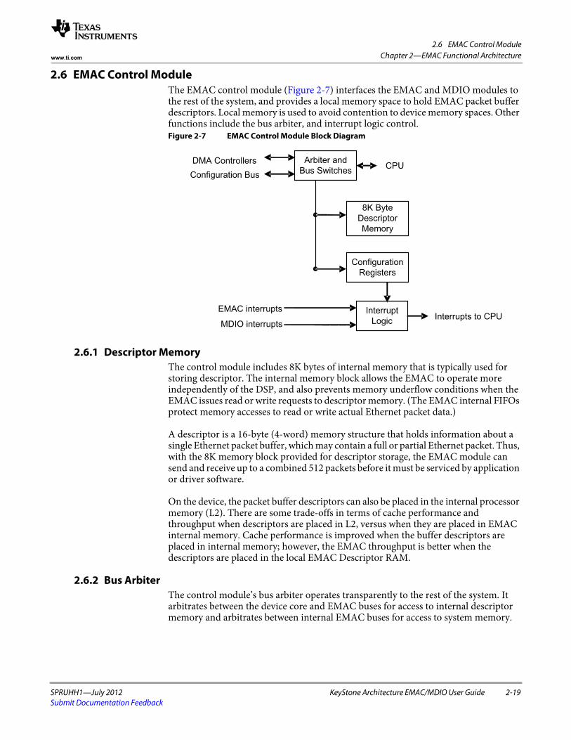
2.6 EMAC Control Module
SPRUHH1—July 2012 KeyStone Architecture EMAC/MDIO User Guide 2-19Submit Documentation Feedback
Chapter 2—EMAC Functional Architecturewww.ti.com
2.6 EMAC Control ModuleThe EMAC control module (Figure 2-7) interfaces the EMAC and MDIO modules to the rest of the system, and provides a local memory space to hold EMAC packet buffer descriptors. Local memory is used to avoid contention to device memory spaces. Other functions include the bus arbiter, and interrupt logic control. Figure 2-7 EMAC Control Module Block Diagram
2.6.1 Descriptor MemoryThe control module includes 8K bytes of internal memory that is typically used for storing descriptor. The internal memory block allows the EMAC to operate more independently of the DSP, and also prevents memory underflow conditions when the EMAC issues read or write requests to descriptor memory. (The EMAC internal FIFOs protect memory accesses to read or write actual Ethernet packet data.)
A descriptor is a 16-byte (4-word) memory structure that holds information about a single Ethernet packet buffer, which may contain a full or partial Ethernet packet. Thus, with the 8K memory block provided for descriptor storage, the EMAC module can send and receive up to a combined 512 packets before it must be serviced by application or driver software.
On the device, the packet buffer descriptors can also be placed in the internal processor memory (L2). There are some trade-offs in terms of cache performance and throughput when descriptors are placed in L2, versus when they are placed in EMAC internal memory. Cache performance is improved when the buffer descriptors are placed in internal memory; however, the EMAC throughput is better when the descriptors are placed in the local EMAC Descriptor RAM.
2.6.2 Bus ArbiterThe control module’s bus arbiter operates transparently to the rest of the system. It arbitrates between the device core and EMAC buses for access to internal descriptor memory and arbitrates between internal EMAC buses for access to system memory.
Arbiter and
Bus Switches
Interrupt
Logic
CPUDMA Controllers
Configuration Bus
EMAC interrupts
MDIO interrupts
8K Byte
Descriptor
Memory
Configuration
Registers
Interrupts to CPU
2.6 EMAC Control Module
2-20 KeyStone Architecture EMAC/MDIO User Guide SPRUHH1—July 2012Submit Documentation Feedback
Chapter 2—EMAC Functional Architecture www.ti.com
2.6.3 Interrupt ControlThe EMAC control module combines the multiple interrupt conditions generated by the EMAC and MDIO modules into 4 interrupt signals like Control, Transmit, Receive and Receive Threshold interrupts that are mapped to the DSP interrupts via the DSP interrupt controller.
There are four interrupt enable registers and an interrupt pacing register. Each bit in these registers corresponds to the RX/TX/RX_THRESH/MISC interrupts that are enabled to generate an interrupt on TX/RX/RX_THRESH/MISC_PULSE.
2.6.3.1 Transmit Interrupt DescriptionThe transmit interrupts are each a paced-pulse interrupt selected from the CPGMAC TXINTSTATRAW interrupts. The transmit pending interrupt(s) is selected by setting one or more bits in the TX_EN register. The masked interrupt status can be read in the TX_STAT address location. Upon reception of an interrupt, the software should perform the following:
• Read the TX_STAT address location to determine which channel(s) caused the interrupt.
• Process received packets for the interrupting channel(s). • Write the CPGMAC completion pointer(s). • Write 0x2 to the MACEOIVECTOR register in the CPGMAC slave address
space. 2.6.3.2 Receive Interrupt Description
The receive interrupts are each a paced-pulse interrupt selected from the CPGMAC RXINTSTATRAW interrupts. The receive pending interrupt(s) is selected by setting one or more bits in the RX_EN register. The masked interrupt status can be read in the RX_STAT address location. Upon reception of an interrupt, software should perform the following:
• Read the RX_STAT address location to determine which channel(s) caused the interrupt.
• Process received packets for the interrupting channel(s). • Write the CPGMAC completion pointer(s). • Write 0x1 to the MACEOIVECTOR register in the CPGMAC slave address
space. 2.6.3.3 Receive Threshold Interrupt Description
The receive threshold interrupts are an immediate (non-paced) pulse interrupt selected from the CPGMAC RXINTSTATRAW interrupts. The receive threshold pending interrupt(s) is selected by setting one or more bits in the RX_THRESH_EN register. The masked interrupt status can be read in the RX_THRESH_STAT address location. Upon reception of an interrupt, software should perform the following:
• Read the RX_THRESH_STAT address location to determine which channel(s) caused the interrupt.
• Process received packets in order to add more buffers to any channel that is below the threshold value.
• Write the CPGMAC completion pointer(s). • Write 0x0 to the MACEOIVECTOR register in the CPGMAC slave address
space.
2.6 EMAC Control Module
SPRUHH1—July 2012 KeyStone Architecture EMAC/MDIO User Guide 2-21Submit Documentation Feedback
Chapter 2—EMAC Functional Architecturewww.ti.com
2.6.3.4 Miscellaneous Interrupt DescriptionThe miscellaneous interrupts are an immediate (non-paced) pulse interrupt selected from the miscellaneous interrupts (STAT_PEND, HOST_PEND, MDIO_LINKINT[0], MDIO_USERINT[0]). The miscellaneous interrupt(s) is selected by setting one or more bits in the MISC_EN register. The masked interrupt status can be read in the MISC_STAT address location. Upon reception of an interrupt, software should perform the following:
• Read the MISC_STAT address location to determine which channel(s) caused the interrupt.
• Process received packets for the interrupting channel(s). • Write the CPGMAC completion pointer(s). • Write 0x3 to the MACEOIVECTOR register in the CPGMAC slave address
space. 2.6.3.5 Interrupt Pacing
The receive and transmit pulse interrupts can be paced. The interrupt pacing feature limits the number of interrupts that occur during the given period of time. The interrupt pacing module counts the number of interrupts that occur over a 1-ms interval of time. At the end of each 1 ms interval, the current number of interrupts is compared with target number of interrupts. Based on the results of the comparison, the length of time during which interrupts are blocked is dynamically adjusted. The 1 ms interval is derived from a 4 μs pulse that is created from a prescale counter whose value is set in the INT_PRESCALE value in the INT_CONTROL register. The INT_PRESCALE value should be written with the number of DSPCLK/6 periods in 4 μs. The pacing timer determines the interval during which interrupts are blocked and decrements every 4 μs. It is reloaded each time a zero count is reached.
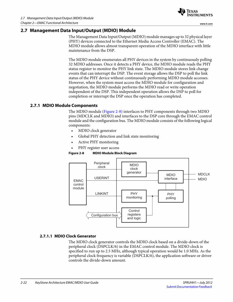
2.7 Management Data Input/Output (MDIO) Module
2-22 KeyStone Architecture EMAC/MDIO User Guide SPRUHH1—July 2012Submit Documentation Feedback
Chapter 2—EMAC Functional Architecture www.ti.com
2.7 Management Data Input/Output (MDIO) ModuleThe Management Data Input/Output (MDIO) module manages up to 32 physical layer (PHY) devices connected to the Ethernet Media Access Controller (EMAC). The MDIO module allows almost transparent operation of the MDIO interface with little maintenance from the DSP.
The MDIO module enumerates all PHY devices in the system by continuously polling 32 MDIO addresses. Once it detects a PHY device, the MDIO module reads the PHY status register to monitor the PHY link state. The MDIO module stores link change events that can interrupt the DSP. The event storage allows the DSP to poll the link status of the PHY device without continuously performing MDIO module accesses. However, when the system must access the MDIO module for configuration and negotiation, the MDIO module performs the MDIO read or write operation independent of the DSP. This independent operation allows the DSP to poll for completion or interrupt the DSP once the operation has completed.
2.7.1 MDIO Module ComponentsThe MDIO module (Figure 2-8) interfaces to PHY components through two MDIO pins (MDCLK and MDIO) and interfaces to the DSP core through the EMAC control module and the configuration bus. The MDIO module consists of the following logical components:
• MDIO clock generator • Global PHY detection and link state monitoring • Active PHY monitoring • PHY register user access
Figure 2-8 MDIO Module Block Diagram
2.7.1.1 MDIO Clock GeneratorThe MDIO clock generator controls the MDIO clock based on a divide-down of the peripheral clock (DSPCLK/6) in the EMAC control module. The MDIO clock is specified to run up to 2.5 MHz, although typical operation would be 1.0 MHz. As the peripheral clock frequency is variable (DSPCLK/6), the application software or driver controls the divide-down amount.
EMACcontrolmodule
Controlregistersand logic
PHYmonitoring
Peripheralclock MDIO
clockgenerator
USERINTMDIO
interface
pollingPHY
MDCLKMDIO
LINKINT
Configuration bus
2.7 Management Data Input/Output (MDIO) Module
SPRUHH1—July 2012 KeyStone Architecture EMAC/MDIO User Guide 2-23Submit Documentation Feedback
Chapter 2—EMAC Functional Architecturewww.ti.com
2.7.1.2 Global PHY Detection and Link State MonitoringThe MDIO module enumerates all PHY devices in the system by continuously polling all 32 MDIO addresses. The module tracks whether a PHY on a particular address has responded and whether the PHY currently has a link. This information allows the software application to quickly determine which MDIO address the PHY is using and if the system is using more than one PHY. The software application can then quickly switch between PHYs based on their current link status.
2.7.1.3 Active PHY MonitoringOnce a PHY candidate has been selected for use, the MDIO module transparently monitors its link state by reading the PHY status register. The MDIO device stores link change events that may optionally interrupt the DSP. Thus, the system can poll the link status of the PHY device without continuously performing MDIO accesses. Up to two PHY devices can be actively monitored at any given time.
2.7.1.4 PHY Register User AccessWhen the DSP must access the MDIO for configuration and negotiation, the PHY access module performs the actual MDIO read or write operation independent of the DSP. Thus, the DSP can poll for completion or receive an interrupt when the read or write operation has been performed. There are two user access registers (USERACCESS0 and USERACCESS1), allowing the software to submit up to two access requests simultaneously. The requests are processed sequentially.
2.7.2 MDIO Module Operational OverviewThe MDIO module implements the 802.3 serial management interface to simultaneously interrogate and control up to two Ethernet PHYs, using a shared two-wired bus. It separately performs auto-detection and records the current link status of up to 32 PHYs, polling all 32 MDIO addresses.
Application software uses the MDIO module to configure the auto-negotiation parameters of the primary PHY attached to the EMAC, retrieve the negotiation results, and configure required parameters in the EMAC. Up to two Ethernet PHYs can be directly controlled and queried. The Media Independent Interface addresses of these two PHY devices are specified in the PHYADRMON fields of the USERPHYSELn register. The module can be programmed to trigger a Cpu interrupt on a PHY link change event by setting the LINKINTENB bit in USERPHYSELn. Reads and writes to registers in these PHY devices are performed using the USERACCESSn register.
The MDIO module powers up in an idle state until it is enabled by setting the ENABLE bit in the CONTROL register. This also configures the MDIO clock divider and preamble mode selection. The MDIO preamble is enabled by default, but it can be disabled if none of the connected PHYs require it.
Once the MDIO module is enabled, the MDIO interface state machine continuously polls the PHY link status (by reading the Generic Status Register) of all possible 32 PHY addresses and records the results in the ALIVE and LINK registers. The corresponding bit for each PHY (0-31) is set in the ALIVE register if the PHY responded to the read request. The corresponding bit is set in the LINK register if the PHY responded and also is currently linked. In addition, any PHY register read transactions initiated by the application software using the USERACCESSn register cause the ALIVE register to be updated.
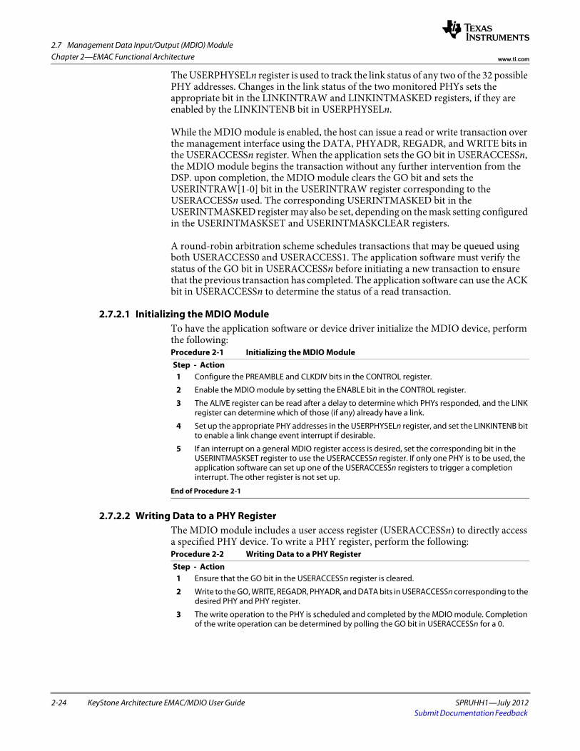
2.7 Management Data Input/Output (MDIO) Module
2-24 KeyStone Architecture EMAC/MDIO User Guide SPRUHH1—July 2012Submit Documentation Feedback
Chapter 2—EMAC Functional Architecture www.ti.com
The USERPHYSELn register is used to track the link status of any two of the 32 possible PHY addresses. Changes in the link status of the two monitored PHYs sets the appropriate bit in the LINKINTRAW and LINKINTMASKED registers, if they are enabled by the LINKINTENB bit in USERPHYSELn.
While the MDIO module is enabled, the host can issue a read or write transaction over the management interface using the DATA, PHYADR, REGADR, and WRITE bits in the USERACCESSn register. When the application sets the GO bit in USERACCESSn, the MDIO module begins the transaction without any further intervention from the DSP. upon completion, the MDIO module clears the GO bit and sets the USERINTRAW[1-0] bit in the USERINTRAW register corresponding to the USERACCESSn used. The corresponding USERINTMASKED bit in the USERINTMASKED register may also be set, depending on the mask setting configured in the USERINTMASKSET and USERINTMASKCLEAR registers.
A round-robin arbitration scheme schedules transactions that may be queued using both USERACCESS0 and USERACCESS1. The application software must verify the status of the GO bit in USERACCESSn before initiating a new transaction to ensure that the previous transaction has completed. The application software can use the ACK bit in USERACCESSn to determine the status of a read transaction.
2.7.2.1 Initializing the MDIO ModuleTo have the application software or device driver initialize the MDIO device, perform the following:
Step - ActionProcedure 2-1 Initializing the MDIO Module
1 Configure the PREAMBLE and CLKDIV bits in the CONTROL register.
2 Enable the MDIO module by setting the ENABLE bit in the CONTROL register.
3 The ALIVE register can be read after a delay to determine which PHYs responded, and the LINK register can determine which of those (if any) already have a link.
4 Set up the appropriate PHY addresses in the USERPHYSELn register, and set the LINKINTENB bit to enable a link change event interrupt if desirable.
5 If an interrupt on a general MDIO register access is desired, set the corresponding bit in the USERINTMASKSET register to use the USERACCESSn register. If only one PHY is to be used, the application software can set up one of the USERACCESSn registers to trigger a completion interrupt. The other register is not set up.
End of Procedure 2-1
2.7.2.2 Writing Data to a PHY RegisterThe MDIO module includes a user access register (USERACCESSn) to directly access a specified PHY device. To write a PHY register, perform the following:
Step - ActionProcedure 2-2 Writing Data to a PHY Register
1 Ensure that the GO bit in the USERACCESSn register is cleared.
2 Write to the GO, WRITE, REGADR, PHYADR, and DATA bits in USERACCESSn corresponding to the desired PHY and PHY register.
3 The write operation to the PHY is scheduled and completed by the MDIO module. Completion of the write operation can be determined by polling the GO bit in USERACCESSn for a 0.
2.7 Management Data Input/Output (MDIO) Module
SPRUHH1—July 2012 KeyStone Architecture EMAC/MDIO User Guide 2-25Submit Documentation Feedback
Chapter 2—EMAC Functional Architecturewww.ti.com
4 Completion of the operation sets the corresponding bit in the USERINTRAW register for the USERACCESSn used. If interrupts have been enabled on this bit using the USERINTMASKSET register, then the bit is also set in the USERINTMASKED register and an interrupt is triggered on the DSP.
End of Procedure 2-2
2.7.2.3 Reading Data From a PHY RegisterThe MDIO module includes a user access register (USERACCESSn) to directly access a specified PHY device. To read a PHY register, perform the following:
Step - ActionProcedure 2-3 Reading Data From a PHY Register
1 Ensure that the GO bit in the USERACCESSn register is cleared.
2 Write to the GO, REGADR, and PHYADR bits in USERACCESSn corresponding to the desired PHY and PHY register.
3 The read data value is available in the DATA bits of USERACCESSn after the module completes the read operation on the serial bus. Completion of the read operation can be determined by polling the GO and ACK bits in USERACCESSn. Once the GO bit has cleared, the ACK bit is set on a successful read.
4 Completion of the operation sets the corresponding bit in the USERINTRAW register for the USERACCESSn used. If interrupts have been enabled on this bit using the USERINTMASKSET register, then the bit is also set in the USERINTMASKED register and an interrupt is triggered on the DSP.
End of Procedure 2-3
2.7.2.4 Example of MDIO Register Access CodeThe MDIO module uses the USERACCESSn register to access the PHY control registers. Software functions that implement the access process include the following four macros:
• PHYREG_read (regadr, phyadr): Start the process of reading a PHY register. • PHYREG_write (regadr, phyadr, data): Start the process of writing a PHY
register. • PHYREG_waitQ: Synchronize operation (make sure read/write is idle). • PHYREG_waitResults (results): Wait for read to complete and return data read.
It is not necessary to wait after a write operation, as long as the status is checked before every operation to make sure the MDIO hardware is idle. An alternative approach is to call PHYREG_wait() after every write, and PHYREG_waitResults() after every read, then the hardware can be assumed to be idle when starting a new operation.
The implementation of these macros using the Chip Support Library (CSL) is shown in Example 2-3 (USERACCESS0 is assumed).
Note that this implementation does not check the ACK bit on PHY register reads; in other words, it does not follow the procedure outlined in Section 2.7.2.3. As the ALIVE register initially selects a PHY, it is assumed that the PHY is acknowledging read operations. It is possible that a PHY could become inactive at a future point in time. For example, a PHY can have its MDIO addresses changed while the system is running, although it is not a common occurrence. This condition can be tested by periodically checking the PHY state in the ALIVE register.
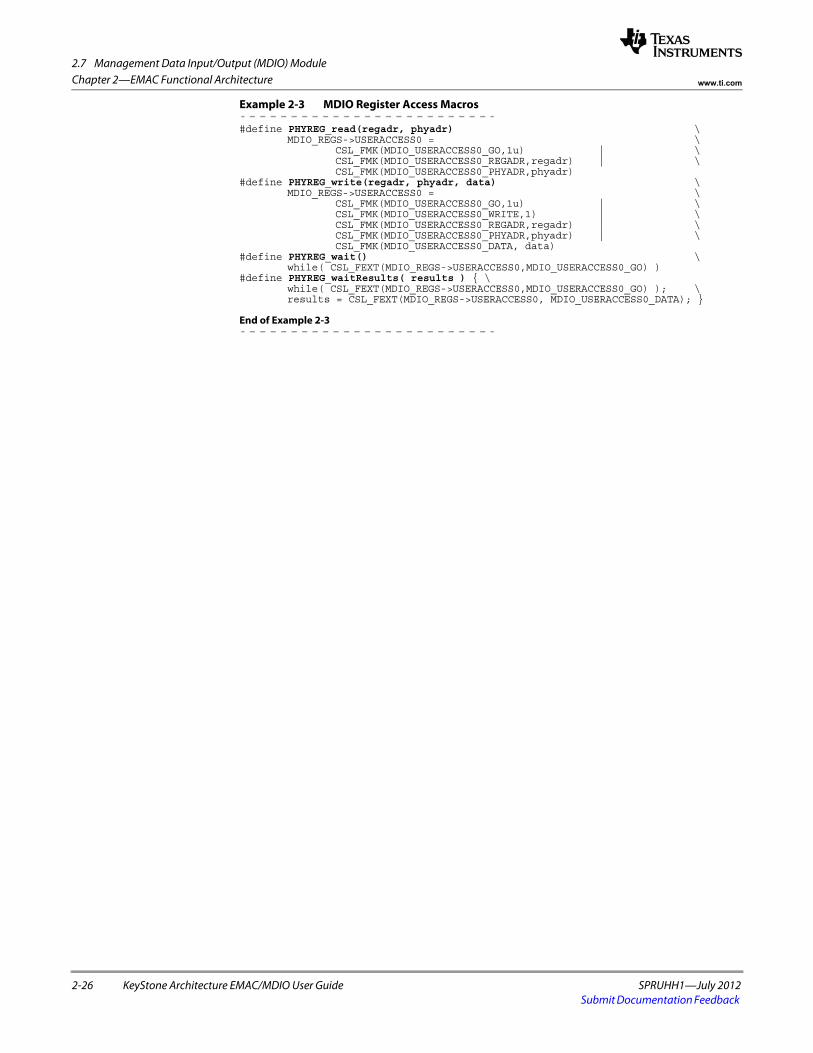
2.7 Management Data Input/Output (MDIO) Module
2-26 KeyStone Architecture EMAC/MDIO User Guide SPRUHH1—July 2012Submit Documentation Feedback
Chapter 2—EMAC Functional Architecture www.ti.com
Example 2-3 MDIO Register Access Macros
#define PHYREG_read(regadr, phyadr) \MDIO_REGS->USERACCESS0 = \
CSL_FMK(MDIO_USERACCESS0_GO,1u) | \CSL_FMK(MDIO_USERACCESS0_REGADR,regadr) | \CSL_FMK(MDIO_USERACCESS0_PHYADR,phyadr)
#define PHYREG_write(regadr, phyadr, data) \MDIO_REGS->USERACCESS0 = \
CSL_FMK(MDIO_USERACCESS0_GO,1u) | \CSL_FMK(MDIO_USERACCESS0_WRITE,1) | \CSL_FMK(MDIO_USERACCESS0_REGADR,regadr) | \CSL_FMK(MDIO_USERACCESS0_PHYADR,phyadr) | \CSL_FMK(MDIO_USERACCESS0_DATA, data)
#define PHYREG_wait() \while( CSL_FEXT(MDIO_REGS->USERACCESS0,MDIO_USERACCESS0_GO) )
#define PHYREG_waitResults( results ) { \while( CSL_FEXT(MDIO_REGS->USERACCESS0,MDIO_USERACCESS0_GO) ); \results = CSL_FEXT(MDIO_REGS->USERACCESS0, MDIO_USERACCESS0_DATA); }
End of Example 2-3
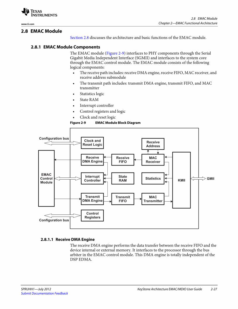
2.8 EMAC Module
SPRUHH1—July 2012 KeyStone Architecture EMAC/MDIO User Guide 2-27Submit Documentation Feedback
Chapter 2—EMAC Functional Architecturewww.ti.com
2.8 EMAC Module Section 2.8 discusses the architecture and basic functions of the EMAC module.
2.8.1 EMAC Module ComponentsThe EMAC module (Figure 2-9) interfaces to PHY components through the Serial Gigabit Media Independent Interface (SGMII) and interfaces to the system core through the EMAC control module. The EMAC module consists of the following logical components:
• The receive path includes: receive DMA engine, receive FIFO, MAC receiver, and receive address submodule
• The transmit path includes: transmit DMA engine, transmit FIFO, and MAC transmitter
• Statistics logic • State RAM• Interrupt controller• Control registers and logic• Clock and reset logic
Figure 2-9 EMAC Module Block Diagram
2.8.1.1 Receive DMA EngineThe receive DMA engine performs the data transfer between the receive FIFO and the device internal or external memory. It interfaces to the processor through the bus arbiter in the EMAC control module. This DMA engine is totally independent of the DSP EDMA.
EMACControlModule
Configuration bus
Configuration bus
Clock andReset Logic
ReceiveDMA Engine
InterruptController
TransmitDMA Engine
ControlRegisters
ReceiveFIFO
StateRAM
TransmitFIFO
ReceiveAddress
MACReceiver
Statistics
MACTransmitter
KMIIGMII
2.8 EMAC Module
2-28 KeyStone Architecture EMAC/MDIO User Guide SPRUHH1—July 2012Submit Documentation Feedback
Chapter 2—EMAC Functional Architecture www.ti.com
2.8.1.2 Receive FIFOThe receive FIFO consists of 68 cells of 64 bytes each and associated control logic. The FIFO buffers receive data in preparation for writing into packet buffers in device memory and also enable receive FIFO flow control.
2.8.1.3 MAC ReceiverThe MAC receiver detects and processes incoming network frames, de-frames them, and places them into the receive FIFO. The MAC receiver also detects errors and passes statistics to the statistics RAM.
2.8.1.4 Receive AddressThis submodule performs address matching and address filtering based on the incoming packets destination address. It contains a 32-by-53 bit two-port RAM in which up to 32 addresses can be stored to be either matched or filtered by the EMAC.
The RAM may contain multicast packet addresses, but the associated channel must have the unicast enable bit set, even though it is a multicast address. The unicast enable bits are used with multicast addresses in the receive address RAM (not the multicast hash enable bits). Therefore, hash matches can be disabled, but specific multicast addresses can be matched (or filtered) in the RAM. If a multicast packet hash matches, the packet may still be filtered in the RAM. Each packet can be sent to only a single channel.
2.8.1.5 Transmit DMA EngineThe transmit DMA engine performs the data transfer between the device internal or external memory and the transmit FIFO. It interfaces to the processor through the bus arbiter in the EMAC control module. This DMA engine is totally independent of the DSP EDMA.
2.8.1.6 Transmit FIFOThe transmit FIFO consists of twenty-four cells of 64 bytes each and associated control logic. This enables the largest allowed packet (1518 bytes) to be sent without the possibility of underrun. The FIFO buffers data in preparation for transmission.
2.8.1.7 MAC TransmitterThe MAC transmitter formats frame data from the transmit FIFO and transmits the data using the CSMA/CD access protocol. The frame CRC can be automatically appended, if required. The MAC transmitter also detects transmission errors and passes statistics to the statistics registers.
2.8.1.8 Statistics Logic The statistics logic RAM counts and stores the Ethernet statistics, keeping track of 36 different Ethernet packet statistics.
2.8.1.9 State RAMThe state RAM contains the head descriptor pointers and completion pointers registers for both transmit and receive channels.
2.8 EMAC Module
SPRUHH1—July 2012 KeyStone Architecture EMAC/MDIO User Guide 2-29Submit Documentation Feedback
Chapter 2—EMAC Functional Architecturewww.ti.com
2.8.1.10 EMAC Interrupt Controller The interrupt controller contains the interrupt related registers and logic. The 26 raw EMAC interrupts are input to this submodule and masked module interrupts are output.
2.8.1.11 Control Registers and LogicThe EMAC is controlled by a set of memory-mapped registers. The control logic also signals transmit, receive, and status related interrupts to the DSP through the EMAC control module.
2.8.1.12 Clock and Reset LogicThe clock and reset submodule generates all the clocks and resets for the EMAC peripheral.
2.8.2 EMAC Module Operational OverviewAfter reset, initialization, and configuration of the EMAC, the application software running on the host may initiate transmit operations. Transmit operations are initiated by host writes to the appropriate transmit channel head descriptor pointer contained in the state RAM block. The transmit DMA controller then fetches the first packet in the packet chain from memory. The DMA controller writes the packet into the transmit FIFO in bursts of 64-byte cells. The MAC transmitter initiates the packet transmission when either the threshold number of cells (configurable via TXCELLTHRESH in the FIFOCONTROL register) have been written to the transmit FIFO, or a complete packet has been written, whichever is smaller. The SYNC block transmits the packet over one of the MIl interfaces in accordance with the 802.3 protocol. The statistics block counts transmit statistics.
Receive operations are initiated by host writes to the appropriate receive channel head descriptor pointer after host initialization and configuration. The SYNC submodule receives packets and strips off the Ethernet related protocol. The packet data is input to the MAC receiver, which checks for address match (in conjunction with the receive address block) and processes errors. Accepted packets are written to the receive FIFO in bursts of 64-byte cells. The receive DMA controller then writes the packet data to memory. The statistics block counts receive statistics.
The EMAC module operates independently of the DSP. It is configured and controlled by its register set mapped into device memory. Information about data packets are communicated using 16-byte descriptors that are placed in an 8K-byte block of RAM in the EMAC control module.
For transmit operations, each 16-byte descriptor describes a packet or packet fragment in the systems internal or external memory. For receive operations, each 16-byte descriptor represents a free packet buffer or buffer fragment. On both transmit and receive, an Ethernet packet is allowed to span one or more memory fragments, represented by one 16-byte descriptor per fragment. In typical operation, there is only one descriptor per receive buffer, but transmit packets may be fragmented, depending on the software architecture.
2.8 EMAC Module
2-30 KeyStone Architecture EMAC/MDIO User Guide SPRUHH1—July 2012Submit Documentation Feedback
Chapter 2—EMAC Functional Architecture www.ti.com
An interrupt is issued to the DSP whenever a transmit or receive operation has completed. However, it is not necessary for the DSP to service the interrupt while there are additional resources available. In other words, the EMAC continues to receive Ethernet packets until its receive descriptor list has been exhausted. On transmit operations, the transmit descriptors need only be serviced to recover their associated memory buffer. Thus, it is possible to delay servicing of the EMAC interrupt if there are real time tasks to perform.
Eight channels are supplied for both transmit and receive operations. On transmit, the eight channels represent eight independent transmit queues. The EMAC can be configured to treat these channels as an equal priority round-robin queue, or as a set of eight fixed-priority queues. On receive, the eight channels represent eight independent receive queues with packet classification. Packets are classified based on the destination MAC address. Each of the eight channels is assigned its own MAC address, enabling the EMAC module to act like eight virtual MAC adapters. Also, specific types of frames can be sent to specific channels. For example, multicast, broadcast, or other (promiscuous, error, etc.) frames can each be received on a specific receive channel queue.
The EMAC tracks 36 different statistics, as well as recording the status of each individual packet in its corresponding packet descriptor.
2.9 Media Independent Interfaces
SPRUHH1—July 2012 KeyStone Architecture EMAC/MDIO User Guide 2-31Submit Documentation Feedback
Chapter 2—EMAC Functional Architecturewww.ti.com
2.9 Media Independent InterfacesThe following sections cover the operation of the Media Independent Interface in 10/100/1000 Mbps modes. An IEEE 802.3 complaint Ethernet MAC controls the interface.
2.9.1 Data Reception2.9.1.1 Receive Control
Data received from the PHY is interpreted and output to the EMAC receive FIFO. Interpretation involves detection and removal of the preamble and start of frame delimiter, extraction of the address and frame length, data handling, error checking and reporting, cyclic redundancy checking (CRC), and statistics control signal generation. Receive address detection and frame filtering of the frames that do not address-match is performed outside the Media Independent Interface.
2.9.1.2 Receive Inter-Frame IntervalThe 802.3 required inter-packet gap (IPG) is 24 GMII clocks (96 bit times) for 10/100 Mbps modes, and 12 GMII clocks (96 bit times) for 1000 Mbps mode. However, the MAC can tolerate a reduced IPG (2 GMII clocks in 10/100 mode and 5 GMII clocks in 1000 mode) with a correct preamble and start frame delimiter. Each receive frame interval is composed of:
1. An inter-packet gap (IPG). 2. A seven octet preamble (all octets 0x55). 3. A one octet start frame delimiter (0x5D).
2.9.1.3 Receive Flow ControlWhen enabled and triggered, receive flow control is initiated to limit the EMAC from further frame reception. Two forms of receive flow control are implemented on the device:
• Receive buffer flow control • Receive FIFO flow control
When enabled and triggered, receive buffer flow control prevents further frame reception based on the number of free buffers available. Receive buffer flow control issues flow control collisions in half-duplex mode and IEEE 802.3X pause frames for full-duplex mode.
Receive buffer flow control is triggered when the number of free buffers in any enabled receive channel (RXnFREEBUFFER) is less than or equal to the channel flow control threshold register (RXnFLOWTHRESH) value. Receive flow control is independent of receive QOS, except that both use the free buffer values.
When enabled and triggered, receive FIFO flow control prevents further frame reception based on the number of cells currently in the receive FIFO. Receive FIFO flow control may be enabled only in full-duplex mode (FULLDUPLEX bit is set in the MACCONTROL register). Receive flow control prevents reception of frames on the port until all of the triggering conditions clear, at which time frames may again be received by the port.
Receive FIFO flow control is triggered when the occupancy of the FIFO is greater than or equal to the RXFIFOFLOWTHRESH value in the FIFOCONTROL register. The RXFIFOFLOWTHRESH value must be greater than or equal to 1h and less than or equal to 42h (decimal 66). The RXFIFOFLOWTHRESH reset value is 2h.
2.9 Media Independent Interfaces
2-32 KeyStone Architecture EMAC/MDIO User Guide SPRUHH1—July 2012Submit Documentation Feedback
Chapter 2—EMAC Functional Architecture www.ti.com
Receive flow control is enabled by the RXBUFFERFLOWEN bit and the RXFIFOFLOWEN bit in the MACCONTROL register. The FULLDUPLEX bit in the MACCONTROL register configures the EMAC for collision or IEEE 802.3X flow control.
2.9.1.4 Collision-Based Receive Buffer Flow ControlCollision-based receive buffer flow control provides a means of preventing frame reception when the EMAC is operating in half-duplex mode (FULLDUPLEX bit is cleared in MACCONTROL register). When receive flow control is enabled and triggered, the EMAC generates collisions for received frames. The jam sequence transmitted is the twelve byte sequence C3.C3.C3.C3.C3.C3.C3.C3.C3.C3.C3.C3 in hexadecimal. The jam sequence begins approximately when the source address starts to be received. Note that these forced collisions are not limited to a maximum of 16 consecutive collisions, and are independent of the normal back-off algorithm.
Receive flow control does not depend on the value of the incoming frame destination address. A collision is generated for any incoming packet, regardless of the destination address, if any EMAC enabled channels free buffer register value is less than or equal to the channels flow threshold value.
2.9.1.5 IEEE 802.3X Based Receive Buffer Flow ControlIEEE 802.3x based receive buffer flow control provides a means of preventing frame reception when the EMAC is operating in full-duplex mode (the FULLDUPLEX bit is set in the MACCONTROL register). When receive flow control is enabled and triggered, the EMAC transmits a pause frame to request that the sending station stop transmitting for the period indicated within the transmitted pause frame.
The EMAC transmits a pause frame to the reserved multicast address at the first available opportunity (immediately if currently idle, or following the completion of the frame currently being transmitted). The pause frame contains the maximum possible value for the pause time (FFFFh). The EMAC counts the receive pause frame time (decrements FF00h to 0) and retransmits an outgoing pause frame, if the count reaches zero. When the flow control request is removed, the EMAC transmits a pause frame with a zero pause time to cancel the pause request.
Note that transmitted pause frames are only a request to the other end station to stop transmitting. Frames that are received during the pause interval are received normally (provided the receive FIFO is not full).
Pause frames are transmitted if enabled and triggered, regardless of whether or not the EMAC is observing the pause time period from an incoming pause frame.
The EMAC transmits pause frames as described below: • The 48-bit reserved multicast destination address 01.80.C2.00.00.01h. • The 48-bit source address (set via the MACSRCADDRLO and
MACSRCADDRHI registers). • The 16-bit length/type field containing the value 88.08h. • The 16-bit pause opcode equal to 00.01h. • The 16-bit pause time value of FF.FFh. A pause-quantum is 512 bit-times. Pause
frames sent to cancel a pause request have a pause time value of 00.00h. • Zero padding to 64-byte data length (EMAC transmits only 64-byte pause
frames).
2.9 Media Independent Interfaces
SPRUHH1—July 2012 KeyStone Architecture EMAC/MDIO User Guide 2-33Submit Documentation Feedback
Chapter 2—EMAC Functional Architecturewww.ti.com
• The 32-bit frame-check sequence (CRC word).
All quantities are hexadecimal and are transmitted most-significant-byte first. The least-significant-bit (LSB) is transferred first in each byte.
If the RXBUFFERFLOWEN bit in the MACCONTROL register is cleared while the pause time is nonzero, then the pause time is cleared and a zero count pause frame is sent.
2.9.2 Data TransmissionThe EMAC passes data to the PHY from the transmit FIFO (when enabled). Data is synchronized to the transmit clock rate. Transmission begins when there are TXCELLTHRESH cells of 64 bytes each, or a complete packet, in the FIFO.
2.9.2.1 Transmit ControlA jam sequence is output if a collision is detected on a transmit packet. If the collision was late (after the first 64 bytes has been transmitted) the collision is ignored. If the collision is not late, the controller will back off before retrying the frame transmission. When operating in full duplex mode the carrier sense (GMII_MCRS) and collision sensing modes are disabled. In full duplex mode, the collision input (GMII_MCOL) operates as a hardware flow control input. No new frames will begin transmission when GMII_MCOL is asserted. However, any frame currently in transmission will complete. Due to the transmission pipeline latency, GMII_MTXEN will not be asserted until up to 10 wire side clocks after the GMII_MCOL signal is de-asserted. Also due to the latency, frame transmission may begin up to 10 wire side clocks after GMII_MCOL is asserted, indicating that the packet transmission was started before the flow control condition was detected.
2.9.2.2 CRC InsertionIf the SOP buffer descriptor PASSCRC flag is cleared, the EMAC generates and appends a 32-bit Ethernet CRC onto the transmitted data. For the EMAC-generated CRC case, a CRC (or placeholder) at the end of the data is allowed but not required. The buffer byte count value should not include the CRC bytes, if they are present.
If the SOP buffer descriptor PASSCRC flag is set, then the last four bytes of the transmit data are transmitted as the frame CRC. The four CRC data bytes should be the last four bytes of the frame and should be included in the buffer byte count value. The MAC performs no error checking on the outgoing CRC.
2.9.2.3 Adaptive Performance Optimization (APO)The EMAC incorporates adaptive performance optimization (APO) logic that may be enabled by setting the TXPACE bit in the MACCONTROL register. Transmission pacing to enhance performance is enabled when the TXPACE bit is set. Adaptive performance pacing introduces delays into the normal transmission of frames, delaying transmission attempts between stations, and reducing the probability of collisions occurring during heavy traffic (as indicated by frame deferrals and collisions). These actions increase the chance of a successful transmission.
When a frame is deferred, suffers a single collision, multiple collisions, or excessive collisions, the pacing counter is loaded with an initial value of 31. When a frame is transmitted successfully (without experiencing a deferral, single collision, multiple collision, or excessive collision), the pacing counter is decremented by 1 down to 0.
2.9 Media Independent Interfaces
2-34 KeyStone Architecture EMAC/MDIO User Guide SPRUHH1—July 2012Submit Documentation Feedback
Chapter 2—EMAC Functional Architecture www.ti.com
If the pacing counter is zero, this allows a new frame to immediately attempt transmission (after one IPG). If the pacing counter is nonzero, the frame is delayed by a pacing delay of approximately four inter-packet gap delays. APO only affects the IPG preceding the first attempt at transmitting a frame; APO does not affect the back-off algorithm for retransmitted frames.
2.9.2.4 Interpacket-Gap (IPG) EnforcementThe measurement reference for the IPG of 96 bit times is changed depending on frame traffic conditions. If a frame is successfully transmitted without collision and MCRS is de-asserted within approximately 48 bit times of MTXEN being de-asserted, then 96 bit times is measured from MTXEN. If the frame suffered a collision or MCRS is not de-asserted until more than approximately 48 bit times after MTXEN is de-asserted, then 96 bit times (approximately, but not less) is measured from MCRS.
2.9.2.5 Back OffThe EMAC implements the 802.3 binary exponential back-off algorithm.
2.9.2.6 Transmit Flow ControlWhen enabled, incoming pause frames are acted upon to prevent the EMAC from transmitting any further frames. Incoming pause frames are only acted upon when the FULLDUPLEX and TXFLOWEN bits in the MACCONTROL register are set. Pause frames are not acted upon in half-duplex mode. Pause frame action is taken if enabled, but normally the frame is filtered and not transferred to memory. MAC control frames are transferred to memory, if the RXCMFEN bit in the RXMBPENABLE register is set. The TXFLOWEN and FULLDUPLEX bits affect whether MAC control frames are acted upon, but they have no effect upon whether MAC control frames are transferred to memory or filtered.
Pause frames are a subset of MAC control frames with an opcode field of 0001h. Incoming pause frames are only acted upon by the EMAC if the following conditions occur:
• The TXFLOWEN bit is set in the MACCONTROL register. • The frames length is between 64 bytes and RXMAXLEN bytes inclusive. • The frame contains no CRC error or align/code errors.
The pause time value from valid frames is extracted from the two bytes following the opcode. The pause time is loaded into the EMAC transmit pause timer and the transmit pause time period begins.
If a valid pause frame is received during the transmit pause time period of a previous transmit pause frame, then either the destination address is not equal to the reserved multicast address or any enabled or disabled unicast address, and the transmit pause timer immediately expires; or the new pause time value is 0, and the transmit pause timer immediately expires. Otherwise, the EMAC transmit pause timer is set immediately to the new pause frame pause time value. (Any remaining pause time from the previous pause frame is discarded.)
If the TXFLOWEN bit in MACCONTROL is cleared, then the pause timer immediately expires.
2.9 Media Independent Interfaces
SPRUHH1—July 2012 KeyStone Architecture EMAC/MDIO User Guide 2-35Submit Documentation Feedback
Chapter 2—EMAC Functional Architecturewww.ti.com
The EMAC does not start the transmission of a new data frame any sooner than 512-bit times after a pause frame with a non-zero pause time has finished being received (MRXDV going inactive). No transmission begins until the pause timer has expired (the EMAC may transmit pause frames to initiate outgoing flow control). Any frame already in transmission when a pause frame is received is completed and unaffected.
Incoming pause frames consist of: • A 48-bit destination address equal to one of the following:
– The reserved multicast destination address 01.80.C2.00.00.01h – Any EMAC 48-bit unicast address. Pause frames are accepted, regardless of
whether the channel is enabled. • The 48-bit source address of the transmitting device • The 16-bit length/type field containing the value 88.08h • The 16-bit pause opcode equal to 00.01h • The 16-bit pause time. A pause-quantum is 512 bit-times • Padding to 64-byte data length • The 32-bit frame-check sequence (CRC word)
All quantities are hexadecimal and are transmitted most-significant-byte first. The least-significant-bit (LSB) is transferred first in each byte.
The padding is required to make up the frame to a minimum of 64 bytes. The standard allows pause frames longer than 64 bytes to be discarded or interpreted as valid pause frames. The EMAC recognizes any pause frame between 64 bytes and RXMAXLEN bytes in length.
2.9.2.7 Speed, Duplex, and Pause Frame SupportThe MAC can operate in half-duplex or full-duplex mode at 10 Mbps or 100 Mbps, and can operate in full duplex only in 1000 Mbps. Pause frame support is included in 10/100/1000 Mbps modes as configured by the host.
2.10 Packet Receive Operation
2-36 KeyStone Architecture EMAC/MDIO User Guide SPRUHH1—July 2012Submit Documentation Feedback
Chapter 2—EMAC Functional Architecture www.ti.com
2.10 Packet Receive OperationSection 2.10 discusses packet receive operations on the device.
2.10.1 Receive DMA Host ConfigurationTo configure the receive DMA for operation, the host must perform the following actions:
• Initialize the receive addresses. • Initialize the RXnHDP registers to zero. • Write the MACHASH1 and MACHASH2 registers, if multicast addressing is
desired. • Initialize the RXnFREEBUFFER, RXnFLOWTHRESH, and
RXFILTERLOWTHRESH registers, if flow control is to be enabled. • Enable the desired receive interrupts using the RXINTMASKSET and
RXINTMASKCLEAR registers. • Set the appropriate configuration bits in the MACCONTROL register. • Write the RXBUFFEROFFSET register value (typically zero). • Set up the receive channel(s) buffer descriptors and initialize the RXnHDP
registers. • Enable the receive DMA controller by setting the RXEN bit in the RXCONTROL
register. • Configure and enable the receive operation, as desired, in the RXMBPENABLE
register and by using the RXUNICASTSET and RXUNICASTCLEAR registers. 2.10.2 Receive Channel Enabling
Each of the eight receive channels has an enable bit (RXCHnEN) in the RXUNICASTSET register that is controlled using the RXUNICASTSET and RXUNICASTCLEAR registers. The RXCHnEN bits determine whether the given channel is enabled (when set to 1) to receive frames with a matching unicast or multicast destination address.
The RXBROADEN bit in the RXMBPENABLE register determines if broadcast frames are enabled or filtered. If broadcast frames are enabled, then they are copied to only a single channel selected by the RXBROADCH field of RXMBPENABLE register.
The RXMULTEN bit in the RXMBPENABLE register determines if hash matching multicast frames are enabled or filtered. Incoming multicast addresses (group addresses) are hashed into an index in the hash table. If the indexed bit is set, the frame hash will match and it will be transferred to the channel selected by the RXMULTCH field when multicast frames are enabled. The multicast hash bits are set in the MACHASH1 and MACHASH2 registers.
The RXPROMCH bits in the RXMBPENABLE register select the promiscuous channel to receive frames selected by the RXCMFEN, RXCSFEN, RXCEFEN, and RXCAFEN bits. These four bits allow reception of MAC control frames, short frames, error frames, and all frames (promiscuous), respectively.
The address RAM can be configured to send multiple unicast and/or multicast addresses to a given channel (if the match bit is set in the RAM). Multicast addresses in the RAM are enabled by the RXUNICASTSET register and not by the RXMULTEN bit in the RXMBPENABLE register. The RXMULTEN bit enables the hash multicast match only. The address RAM takes precedence over the hash match.
2.10 Packet Receive Operation
SPRUHH1—July 2012 KeyStone Architecture EMAC/MDIO User Guide 2-37Submit Documentation Feedback
Chapter 2—EMAC Functional Architecturewww.ti.com
If a multicast packet is received that hash matches (multicast packets enabled), but is filtered in the RAM, then the packet is filtered. If a multicast packet does not hash match, regardless of whether or not hash matching is enabled, but matches an enabled multicast address in the RAM, then the packet will be transferred to the associated channel.
2.10.3 Receive Channel AddressingThe receive address block can store up to 32 addresses to be filtered or matched. Before enabling packet reception, all the address RAM locations should be initialized, including locations to be unused. The system software is responsible for adding and removing addresses from the RAM.
A MAC address location in RAM is 53 bits wide and consists of: • 48 bits of the MAC address • 3 bits for the channel to which a valid address match will be transferred. The
channel is a don't care if MATCHFILT bit is cleared. • A valid bit • A match or filter bit
The procedure for adding an entry to the address RAM is discussed in Procedure 2-4.
Step - ActionProcedure 2-4 Adding an Entry to the Address RAM
1 Write the index into the address RAM in the MACINDEX register to start writing a MAC address.
2 Write the upper 32 bits of the MAC address (MACADDRHI register)
3 Write the lower 16 bits of MAC address with the VALID and MATCHFILT control bits (MACADDRL0). The valid bit should be cleared for the unused locations in the receive address RAM.
The most common uses for the receive address submodule are: • Set EMAC in promiscuous mode, using RXCAFEN and RXPROMCH bits in the
RXMBPENABLE register. Then filter up to 32 individual addresses, which can be both unicast and/or multicast.
• Disable the promiscuous mode (RXCAFEN = 0) and match up to 32 individual addresses, multicast and/or unicast.
2.10.4 Hardware Receive QOS SupportHardware receive quality of service (QOS) is supported, when enabled, by the Tag Protocol Identifier format and the associated Tag Control Information (TCI) format priority field. When the incoming frame length/type value is equal to 81.00h, the EMAC recognizes the frame as an Ethernet Encoded Tag Protocol Type. The two octets immediately following the protocol type contain the 16-bit TCI field. Bits 15-13 of the TCI field contain the received frames priority (0 to 7). The received frame is a low-priority frame if the priority value is 0 to 3. The received frame is a high-priority frame if the priority value is 4 to 7. All frames that have a length/type field value not equal to 81.00h are low-priority frames.
2.10 Packet Receive Operation
2-38 KeyStone Architecture EMAC/MDIO User Guide SPRUHH1—July 2012Submit Documentation Feedback
Chapter 2—EMAC Functional Architecture www.ti.com
Received frames that contain priority information are determined by the EMAC as: • A 48-bit (6 bytes) destination address equal to:
– The destination stations individual unicast address. – The destination stations multicast address (MACHASH1 and MACHASH2
registers). – The broadcast address of all ones.
• A 48-byte (6 bytes) source address. • The 16-bit (2 bytes) length/type field containing the value 81.00h. • The 16-bit (2 bytes) TCI field with the priority field in the upper 3 bits. • Data bytes. • The 4-bytes CRC.
The RXFILTERLDWTHRESH and the RXnFREEBUFFER registers are used in conjunction with the priority information to implement receive hardware QOS. Low-priority frames are filtered if the number of free buffers (RXnFREEBUFFER) for the frame channel is less than or equal to the filter low threshold (RXFILTERLOWTHRESH) value. Hardware QOS is enabled by the RXQOSEN bit in the RXMBPENABLE register.
2.10.5 Host Free Buffer TrackingThe host must track free buffers for each enabled channel (including unicast, multicast, broadcast, and promiscuous) if receive QOS or receive flow control is used. Disabled channel free buffer values are don't cares. During initialization, the host should write the number of free buffers for each enabled channel to the appropriate RXnFREEBUFFER register. The EMAC decrements the appropriate channels free buffer value for each buffer used. When the host reclaims the frame buffers, the host should write the channel free buffer register with the number of reclaimed buffers (write to increment). There are a maximum of 65535 free buffers available. The RXnFREEBUFFER registers only need to be updated by the host if receive QOS or flow control is used.
2.10.6 Receive Channel TeardownThe host commands a receive channel teardown by writing the channel number to the RXTEARDOWN register. When a teardown command is issued to an enabled receive channel, the following occurs:
• Any current frame in reception completes normally. • The TDOWNCMPLT flag is set in the next buffer descriptor in the chain, if there
is one. • The channel head descriptor pointer is cleared. • A receive interrupt for the channel is issued to the host. • The corresponding RXnCP register contains the value FFFF FFFCh. • The host should acknowledge a teardown interrupt with an FFFF FFFCh
acknowledge value.
Channel teardown may be commanded on any channel at any time. The host is informed of the teardown completion by the set teardown complete buffer descriptor bit. The EMAC does not clear any channel enables due to a teardown command. A teardown command to an inactive channel issues an interrupt that software should
2.10 Packet Receive Operation
SPRUHH1—July 2012 KeyStone Architecture EMAC/MDIO User Guide 2-39Submit Documentation Feedback
Chapter 2—EMAC Functional Architecturewww.ti.com
acknowledge with an FFFF FFFCh acknowledge value to RXnCP (note that there is no buffer descriptor in this case). Software may read RXnCP to determine if the interrupt was due to a commanded teardown. The read value is FFFF FFFCh if the interrupt was due to a teardown command.
2.10.7 Receive Frame ClassificationReceived frames are proper, or good, frames if they are between 64 and RXMAXLEN in length (inclusive) and contain no code, align, or CRC errors.
Received frames are long frames if their frame count exceeds the value in the RXMAXLEN register. The RXMAXLEN register default reset value is 5EEh (1518 in decimal). Long received frames are either oversized or jabber frames. Long frames with no errors are oversized frames; long frames with CRC, code, or alignment errors are jabber frames.
Received frames are short frames if their frame count is less than 64 bytes. Short frames that address match and contain no errors are undersized frames; short frames with CRC, code, or alignment errors are fragment frames. If the frame length is less than or equal to 20, then the frame CRC is passed regardless of whether the RXPASSCRC bit is set or cleared in the RXMBPENABLE register.
A received long packet always contains RXMAXLEN number of bytes transferred to memory (if the RXCEFEN bit is set in RXMBPENABLE) regardless of the value of the RXPASSCRC bit. Following is an example with RXMAXLEN set to 1518:
• If the frame length is 1518, then the packet is not a long packet and there are 1514 or 1518 bytes transferred to memory depending on the value of the RXPASSCRC bit.
• If the frame length is 1519, there are 1518 bytes transferred to memory regardless of the RXPASSCRC bit value. The last three bytes are the first three CRC bytes.
• If the frame length is 1520, there are 1518 bytes transferred to memory regardless of the RXPASSCRC bit value. The last two bytes are the first two CRC bytes.
• If the frame length is 1521, there are 1518 bytes transferred to memory regardless of the RXPASSCRC bit value. The last byte is the first CRC byte.
• If the frame length is 1522, there are 1518 bytes transferred to memory. The last byte is the last data byte.
2.10.8 Promiscuous Receive ModeWhen the promiscuous receive mode is enabled by setting the RXCAFEN bit in the RXMBPENABLE register, non-address matching frames that would normally be filtered are transferred to the promiscuous channel. Address matching frames that would normally be filtered due to errors are transferred to the address match channel when RXCAFEN and RXCEFEN bits are set. Address matching frames with the filter bit set (MATCHFILT = 0) are always filtered regardless of the RXCAFEN and RXCEFEN bit selling. A frame is considered to be an address matching frame only if it is enabled to be received on a unicast, multicast, or broadcast channel. Frames received to disabled unicast, multicast, or broadcast channels are considered non-address matching.
MAC control frames address match only if RXCMFEN bit is set. RXCEFEN and RXCSFEN determine whether error frames are transferred to memory or not, but they do not determine whether error frames are address matching or not. Short frames are a special type of error frames.
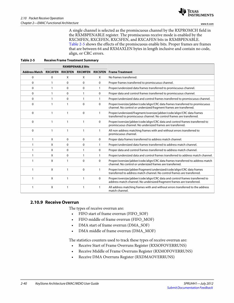
2.10 Packet Receive Operation
2-40 KeyStone Architecture EMAC/MDIO User Guide SPRUHH1—July 2012Submit Documentation Feedback
Chapter 2—EMAC Functional Architecture www.ti.com
A single channel is selected as the promiscuous channel by the RXPROMCH field in the RXMBPENABLE register. The promiscuous receive mode is enabled by the RXCMFEN, RXCEFEN, RXCSFEN, and RXCAFEN bits in RXMBPENABLE. Table 2-5 shows the effects of the promiscuous enable bits. Proper frames are frames that are between 64 and RXMAXLEN bytes in length inclusive and contain no code, align, or CRC errors.
2.10.9 Receive OverrunThe types of receive overrun are:
• FIFO start of frame overrun (FIFO_SOF) • FIFO middle of frame overrun (FIFO_MOF) • DMA start of frame overrun (DMA_SOF) • DMA middle of frame overrun (DMA_MOF)
The statistics counters used to track these types of receive overrun are: • Receive Start of Frame Overruns Register (RXSOFOVERRUNS) • Receive Middle of Frame Overruns Register (RXMOFOVERRUNS) • Receive DMA Overruns Register (RXDMAOVERRUNS)
Table 2-5 Receive Frame Treatment Summary
Address Match
RXMBPENABLE Bits
Frame Treatment RXCAFEN RXCEFEN RXCMFEN RXCSFEN
0 0 X X X No frames transferred.
0 1 0 0 0 Proper frames transferred to promiscuous channel.
0 1 0 0 1 Proper/undersized data frames transferred to promiscuous channel.
0 1 0 1 0 Proper data and control frames transferred to promiscuous channel.
0 1 0 1 1 Proper/undersized data and control frames transferred to promiscuous channel.
0 1 1 0 0 Proper/oversize/jabber/code/align/CRC data frames transferred to promiscuous channel. No control or undersized/fragment frames are transferred.
0 1 1 0 1 Proper/undersized/fragment/oversize/jabber/code/align/CRC data frames transferred to promiscuous channel. No control frames are transferred.
0 1 1 1 0 Proper/oversize/jabber/code/align/CRC data and control frames transferred to promiscuous channel. No undersized frames are transferred.
0 1 1 1 1 All non-address matching frames with and without errors transferred to promiscuous channel.
1 X 0 0 0 Proper data frames transferred to address match channel.
1 X 0 0 1 Proper/undersized data frames transferred to address match channel.
1 X 0 1 0 Proper data and control frames transferred to address match channel.
1 X 0 1 1 Proper/undersized data and control frames transferred to address match channel.
1 X 1 0 0 Proper/oversize/jabber/code/align/CRC data frames transferred to address match channel. No control or undersized frames are transferred.
1 X 1 0 1 Proper/oversize/jabber/fragment/undersized/code/align/CRC data frames transferred to address match channel. No control frames are transferred.
1 X 1 1 0 Proper/oversize/jabber/code/align/CRC data and control frames transferred to address match channel. No undersized/fragment frames are transferred.
1 X 1 1 1 All address matching frames with and without errors transferred to the address match channel.
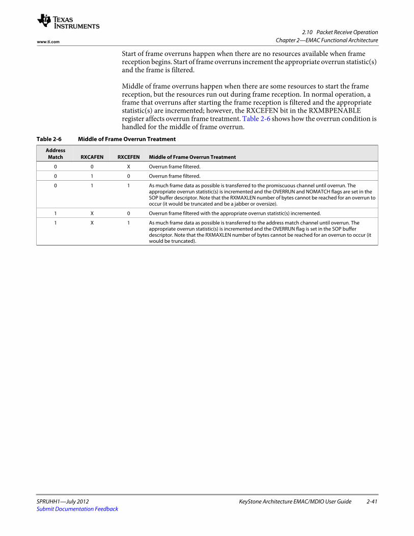
2.10 Packet Receive Operation
SPRUHH1—July 2012 KeyStone Architecture EMAC/MDIO User Guide 2-41Submit Documentation Feedback
Chapter 2—EMAC Functional Architecturewww.ti.com
Start of frame overruns happen when there are no resources available when frame reception begins. Start of frame overruns increment the appropriate overrun statistic(s) and the frame is filtered.
Middle of frame overruns happen when there are some resources to start the frame reception, but the resources run out during frame reception. In normal operation, a frame that overruns after starting the frame reception is filtered and the appropriate statistic(s) are incremented; however, the RXCEFEN bit in the RXMBPENABLE register affects overrun frame treatment. Table 2-6 shows how the overrun condition is handled for the middle of frame overrun.
Table 2-6 Middle of Frame Overrun Treatment
Address Match RXCAFEN RXCEFEN Middle of Frame Overrun Treatment
0 0 X Overrun frame filtered.
0 1 0 Overrun frame filtered.
0 1 1 As much frame data as possible is transferred to the promiscuous channel until overrun. The appropriate overrun statistic(s) is incremented and the OVERRUN and NOMATCH flags are set in the SOP buffer descriptor. Note that the RXMAXLEN number of bytes cannot be reached for an overrun to occur (it would be truncated and be a jabber or oversize).
1 X 0 Overrun frame filtered with the appropriate overrun statistic(s) incremented.
1 X 1 As much frame data as possible is transferred to the address match channel until overrun. The appropriate overrun statistic(s) is incremented and the OVERRUN flag is set in the SOP buffer descriptor. Note that the RXMAXLEN number of bytes cannot be reached for an overrun to occur (it would be truncated).
2.11 Packet Transmit Operation
2-42 KeyStone Architecture EMAC/MDIO User Guide SPRUHH1—July 2012Submit Documentation Feedback
Chapter 2—EMAC Functional Architecture www.ti.com
2.11 Packet Transmit OperationThe transmit DMA is an eight channel interface. Priority between the eight queues may be either fixed or round robin as selected by the TXPTYPE bit in the MACCONTROL register. If the priority type is fixed, then channel 7 has the highest priority and channel 0 has the lowest priority. Round robin priority proceeds from channel 0 to channel 7.
2.11.1 Transmit DMA Host ConfigurationTo configure the transmit DMA for operation, the host must perform the following:
• Write the MACSRCADDRLO and MACSRCADDRHI registers (used for pause frames on transmit).
• Initialize the TXnHDP registers to zero. • Enable the desired transmit interrupts using the TXINTMASKSET and
TXINTMASKCLEAR registers. • Set the appropriate configuration bits in the MACCONTROL register. • Set up the transmit channel(s) buffer descriptors in host memory. • Enable the transmit DMA controller by setting the TXEN bit in the
TXCONTROL register. • Write the appropriate TXnHDP registers with the pointer to the first descriptor
to start transmit operations. 2.11.2 Transmit Channel Teardown
The host commands a transmit channel teardown by writing the channel number to the TXTEARDOWN register. When a teardown command is issued to an enabled transmit channel, the following occurs:
• Any frame currently in transmission completes normally. • The TDOWNCMPLT flag is set in the next SOP buffer descriptor in the chain, if
there is one. • The channel head descriptor pointer is cleared. • A transmit interrupt is issued, informing the host of the channel teardown. • The corresponding TXnCP register contains the value FFFF FFFCh. • The host should acknowledge a teardown interrupt with an FFFF FFFCh
acknowledge value.
Channel teardown may be commanded on any channel at any time. The host is informed of the teardown completion by the set teardown complete buffer descriptor bit (TDOWNCMPLT). The EMAC does not clear any channel enables due to a teardown command. A teardown command to an inactive channel issues an interrupt that software should acknowledge with an FFFF FFFCh acknowledge value to TXnCP (note that there is no buffer descriptor). Software may read the interrupt acknowledge location (TXnCP) to determine if the interrupt was due to a commanded teardown. The read value is FFFF FFFCh if the interrupt was due to a teardown command.
2.12 Receive and Transmit Latency
SPRUHH1—July 2012 KeyStone Architecture EMAC/MDIO User Guide 2-43Submit Documentation Feedback
Chapter 2—EMAC Functional Architecturewww.ti.com
2.12 Receive and Transmit LatencyThe transmit FIFO contains twenty four 64-byte cells, and the receive FIFO contains sixty eight 64-byte cells. The EMAC begins transmission of a packet on the wire after TXCELLTHRESH cells (configurable through the FIFOCONTROL register) or a complete packet are available in the FIFO.
Transmit underrun cannot occur for packet sizes of TXCELLTHRESH times 64 bytes (or less). For larger packet sizes, transmit underrun can occur if the memory latency is greater than the time required to transmit a 64-byte cell on the wire; this is 0.512 s in 1000 Mbps mode, 5.12 s in 100 Mbps mode, and 51.2 s in 10 Mbps mode. The memory latency time includes all buffer descriptor reads for the entire cell data.
The EMAC transmit FIFO uses 24 cells; thus, underrun cannot happen for a normal size packet (less than 1536 packet bytes). Cell transmission can be configured to start only after an entire packet is contained in the FIFO; for a maximum-size packet, set the TXCELLTHRESH field to the maximum possible value of 24.
Receive overrun is prevented if the receive memory cell latency is less than the time required to transmit a 64-byte cell on the wire (0.512 s in 1000 Mbps mode, 5.12 s in 100 Mbps mode, or 51.2s in 10 Mbps mode).
The latency time includes any required buffer descriptor reads for the cell data. Latency to systems internal and external RAM can be controlled through the use of the transfer node priority allocation register in the devices. Latency to descriptor RAM is low because RAM is local to the EMAC, as it is part of the EMAC control module.
2.13 Transfer Node Priority
2-44 KeyStone Architecture EMAC/MDIO User Guide SPRUHH1—July 2012Submit Documentation Feedback
Chapter 2—EMAC Functional Architecture www.ti.com
2.13 Transfer Node PriorityThe devices contain a system level priority allocation register (PRI_ALLOC) that sets the priority of the transfer node used in issuing memory transfer requests to system memory.
Although the EMAC has internal FIFOs to help alleviate memory transfer arbitration problems, the average transfer rate of data read and written by the EMAC to internal or external DSP memory must be at least equal to the Ethernet wire rate. In addition, the internal FIFO system can not withstand a single memory latency event greater than the time it takes to fill or empty a TXCELLTHRESH number of internal 64-byte FIFO cells.
For example, for 1000 Mbps operation, these restrictions translate into the following rules:
• For the short-term average, each 64-byte memory read/write request from the EMAC must be serviced in no more than 0.512 seconds.
• Any single latency event in request servicing can be no longer than (0.512 * TXCELLTHRESH) seconds.
Bits [2-0] of the PRI_ALLOC register set the transfer node priority for all the master peripherals in the device, including EMAC. A value of 000b will have the highest priority, while 111 b will have the lowest. The default priority assigned to EMAC is 001b. It is important to have a balance between all peripherals. In most cases, the default priorities will not need adjustment.
2.14 Reset Considerations
SPRUHH1—July 2012 KeyStone Architecture EMAC/MDIO User Guide 2-45Submit Documentation Feedback
Chapter 2—EMAC Functional Architecturewww.ti.com
2.14 Reset Considerations2.14.1 Software Reset Considerations
For information on the chip level reset capabilities of various peripherals, see the data manual for your product.
Within the peripheral itself, the EMAC component of the Ethernet MAC peripheral can be placed in a reset state by writing to the SOFTRESET register located in EMAC memory map. Writing a one to bit 0 of this register causes the EMAC logic to be reset, and the register values to be set to their default values. Software reset occurs when the receive and transmit DMA controllers are in an idle state to avoid locking up the configuration bus; it is the responsibility of the software to verify that there are no pending frames to be transferred. After writing a one to this bit, it may be polled to determine if the reset has occurred. A value of one indicates that the reset has not yet occurred. A value of zero indicates that a reset has occurred.
After software reset operation, all the EMAC registers need to be re-initialized for proper data transmission.
The error interrupts (HOSTPEND) can be recovered by using the software reset operation. Before doing a software reset, you should inspect the error codes in the MACSTATUS register. This register provides information about the software error type that needs correction. For more information on error interrupts, see Section 2.16.1.5.
2.14.2 Hardware Reset ConsiderationsWhen a hardware reset occurs, the EMAC peripheral will have its register values reset, and all the sub modules will return to their default state. After the hardware reset, the EMAC needs to be initialized before resuming its data transmission, as described in Section 2.15.
A hardware reset can also be used to recover from the error interrupts (HOSTPEND), which are triggered by errors in packet buffer descriptors. Before doing a hardware reset, you should inspect the error codes in the MACSTATUS register. This register provides information about the software error type that needs correction. For more information on error interrupts, see Section 2.16.1.5.
2.15 Initialization
2-46 KeyStone Architecture EMAC/MDIO User Guide SPRUHH1—July 2012Submit Documentation Feedback
Chapter 2—EMAC Functional Architecture www.ti.com
2.15 InitializationThis section discusses the initialization procedure for the EMAC control module, the MDIO, and the EMAC module.
2.15.1 EMAC Control Module InitializationThe EMAC control module is used for global interrupt enable, and to pace back-to-back interrupts using an interrupt re-trigger count based on the peripheral clock (DSPCLK/6). There is also an 8K block of RAM local to the EMAC that holds packet buffer descriptors.
Note that although the EMAC control module and the EMAC module have slightly different functions, in practice, the type of maintenance performed on the EMAC control module is more commonly conducted from the EMAC module software (as opposed to the MDIO module).
The initialization of the EMAC control module consists of two parts: 1. Configuration of the interrupt on the DSP. 2. Initialization of the EMAC control module:
– Setting the interrupt pace count (using the INT_CONTROL register)– Initializing the EMAC and MDIO modules – Enabling interrupts in the EMAC control module
To view example code used to perform the actions associated with the second part of the EMAC control module initialization when using the register-level CSL, see Example 2-4.
Use the systems interrupt controller to map the EMAC interrupts to one of the DSP interrupts. Once the interrupts are mapped to the DSP interrupts, general masking and unmasking of the interrupt (to control reentrance) should be done at the chip level by manipulating the interrupt enable mask. The EMAC control module control registers should only enable and disable interrupts from within the EMAC interrupt service routine (ISR), as disabling and re-enabling the interrupts in the CONTROL registers also resets the interrupt pace counter.
Example 2-4 EMAC Control Module Initialization Code
/*// Disable EMAC/MDIO interrupts in the control module/*ECTL_REGS->TX_EN = 0x0;ECTL_REGS->RX_EN = 0x0;ECTL_REGS->RX_THRESH_EN = 0;ECTL_REGS->MISC_EN = 0x0;/*// Enable EMAC/MDIO interrupts in the control module*/ECTL_REGS->TX_EN = 0xFF;ECTL_REGS->RX_EN = 0xFF;ECTL_REGS->RX_THRESH_EN = 0xFF;ECTL_REGS->MISC_EN = 0xF;
End of Example 2-4
2.15 Initialization
SPRUHH1—July 2012 KeyStone Architecture EMAC/MDIO User Guide 2-47Submit Documentation Feedback
Chapter 2—EMAC Functional Architecturewww.ti.com
2.15.2 MDIO Module InitializationThe MDIO module initially configures and monitors one or more external PHY devices. Other than initializing the software state machine (details on the MDIO state machine can be found in the IEEE 802.3 standard), the MDIO module only needs the MDIO engine enabled and the clock divider configured. To set the clock divider, supply an MDIO clock of 1 MHz. As the peripheral clock is used as the base clock (DSPCLK/6), the divider can be set to 125 for a 750 MHz device. Slower MDIO clocks for slower DSP frequencies are acceptable.
Both the state machine enable and the MDIO clock divider are controlled through the MDIO control register (CONTROL). If none of the potentially connected PHYs require the access preamble, the PREAMBLE bit can also be set in the CONTROL register to speed up PHY register access. For an example of the initialization code, see Example 5.
Example 2-5 MDIO Module Initialization Code
#define MDIO_MODEFLG_FD1000 0x0020#define MDIO_MODEFLG_EXTLOOPBACK 0x0100Uint32 mdioModeFlags = MDIO_MODEFLG_FD1000 | MDIO_MODEFLG_LOOPBACK;Handle hMDIO;volatile Uint32 phyAddr;//Open the MDIO modulehMDIO = MDIO_open ( mdioModeFlags );
// Initialize PHYMDIO_initPHY( hMDIO, phyAddr );
End of Example 2-5
If the MDIO module must operate on an interrupt basis, the interrupts can be enabled at this time using the USERINTMASKSET register for register access and the USERPHYSELn register if a target PHY is already known.
Once the MDIO state machine has been initialized and enabled, it starts polling all 32 PHY addresses on the MDIO bus, looking for active PHYs. Since it can take up to 50 s to read one register, the MDIO module provides an accurate representation of all the PHY5 available after a reasonable interval. Also, a PHY can take up to 3 seconds to negotiate a link Thus, it is advisable to run the MDIO software off a time-based event rather than polling.
For more information on PHY control registers, see the PHY data sheet.
2.15.3 EMAC Module InitializationThe EMAC module sends and receives data packets over the network by maintaining up to 8 transmit and receive descriptor queues. The EMAC module configuration must also be kept current based on the PHY negotiation results returned from the MDIO module. Programming this module is the most time-consuming aspect of developing an application or device driver for Ethernet.
A device driver should follow this initialization procedure to get the EMAC to the state where it is ready to receive and send Ethernet packets. Some of these steps are not necessary when performed immediately after device reset.
Step - ActionProcedure 2-5 EMAC Module Initialization
1 If enabled, clear EMAC/MDIO interrupts in the control module.
2 Clear the MACCONTROL, RXCONTROL, and TXCONTROL registers (not necessary immediately after reset).
2.15 Initialization
2-48 KeyStone Architecture EMAC/MDIO User Guide SPRUHH1—July 2012Submit Documentation Feedback
Chapter 2—EMAC Functional Architecture www.ti.com
3 Initialize all 16 Head Descriptor Pointer registers (RXnHDP and TXnHDP) to 0.
4 Clear all 36 statistics registers by writing 0 (not necessary immediately after reset).
5 Initialize all 32 receive address RAM locations to 0. Set up the addresses to be matched to the eight receive channels and the addresses to be filtered, through programming the MACINDEX, MACADDRHI, and MACADDRLO registers.
6 Initialize the RXnFREEBUFFER, RXnFLOWTHRESH, and RXFILTERLOWTHRESH registers, if buffer flow control is to be enabled. Program the FIFOCONTROL register is FIFO flow control is desired.
7 Most device drivers open with no multicast addresses, so clear the MACHASH1 and MACHASH2 registers.
8 Write the RXBUFFEROFFSET register value (typically zero).
9 Initially clear all unicast channels by writing FFh to the RXUNICASTCLEAR register. If unicast is desired, it can be enabled now by writing the RXUNICASTSET register. Some drivers will default to unicast on device open while others will not.
10 Set up the RXMBPENABLE register with an initial configuration. The configuration is based on the current receive filter settings of the device driver. Some drivers may enable things like broadcast and multicast packets immediately, while others may not.
11 Set the appropriate configuration bits in the MACCONTROL register (do not set the GMlIEN bit yet).
12 Clear all unused channel interrupt bits by writing RXINTMASKCLEAR and TXINTMASKCLEAR.
13 Enable the receive and transmit channel interrupt bits in RXINTMASKSET and TXINTMASKSET for the channels to be used, and enable the HOSTMASK and STATMASK bits using the MACINTMASKSET register.
14 Initialize the receive and transmit descriptor list queues using the 8K descriptor memory block contained in the EMAC control module.
15 Prepare receive by writing a pointer to the head of the receive buffer descriptor list to RXnHDP.
16 Enable the receive and transmit DMA controllers by setting the RXEN bit in the RXCONTROL register and the TXEN bit in the TXCONTROL register. Then set the GMlIEN bit in MACCONTROL.
17 If the gigabit mode is desired, set the GIG bit in the MACCONTROL register. Alternatively, enable the gigabit mode by setting the EXT_EN bit in the MACCONTROL register to allows the speed and duplexity to be input from the SGMII interface.
18 Enable the EMAC/MDIO interrupts in the control module.
End of Procedure 2-5
2.16 Interrupt Support
SPRUHH1—July 2012 KeyStone Architecture EMAC/MDIO User Guide 2-49Submit Documentation Feedback
Chapter 2—EMAC Functional Architecturewww.ti.com
2.16 Interrupt SupportThis section discusses the interrupts for the EMAC and MDIO modules.
2.16.1 EMAC Module Interrupt Events and RequestsThe EMAC/MDIO generates 26 interrupts, as follows:
• TXPENDn: Transmit packet completion interrupt for transmit channels 7 through 0.
• RXPENDn: Receive packet completion interrupt for receive channels 7 through 0.
• RXTHRESHPENDn: Receive Threshold interrupt for receive channels 7 through 0.
• STATPEND: Statistics interrupt.• HOSTPEND: Host error interrupt.
2.16.1.1 Transmit Packet Completion InterruptsThe transmit DMA engine has eight channels, and each channel has a corresponding interrupt (TXPENDn). The transmit interrupts are level interrupts that remain asserted until cleared by the DSP.
Each of the eight transmit channel interrupts may be individually enabled by setting the appropriate bit in the TXINTMASKSET register. Each of the eight transmit channel interrupts may be individually disabled by clearing the appropriate bit in the TXINTMASKCLEAR register. The raw and masked transmit interrupt status may be read by reading the TXINTSTATRAW and TXINTSTATMASKED registers, respectively.
When the EMAC completes the transmission of a packet, the EMAC issues an interrupt to the DSP by writing the last buffer descriptor address of TX completion pointer to the appropriate channel queue located in the state RAM block. The write generates the interrupt when enabled by the interrupt mask, regardless of the value written.
Upon interrupt reception, the DSP processes one or more packets from the buffer chain. The interrupt is acknowledged by writing the address of the last buffer descriptor processed to the associated TX completion pointer in the transmit DMA state RAM.
The data written by the host (buffer descriptor address of the last processed buffer) is compared to the data in the register written by the EMAC port (address of last buffer descriptor used by the EMAC). If the two values are not equal, indicating that the EMAC has transmitted more packets than the DSP has processed interrupts for, then the transmit packet completion interrupt signal remains asserted. If the two values are equal, indicating that the host has processed all packets that the EMAC has transferred, then the pending interrupt is cleared. Reading the TXnCP register displays the value that the EMAC is expecting.
The EMAC write to the completion pointer stores the value in the state RAM. The DSP written value does not change the register value. The host-written value is compared to the register content, which was written by the EMAC. If the two values are equal, then the interrupt is removed; otherwise the interrupt remains asserted. The host may process multiple packets prior to acknowledging an interrupt, or the host may acknowledge interrupts for every packet.
2.16 Interrupt Support
2-50 KeyStone Architecture EMAC/MDIO User Guide SPRUHH1—July 2012Submit Documentation Feedback
Chapter 2—EMAC Functional Architecture www.ti.com
2.16.1.2 Receive Packet Completion InterruptsThe receive DMA engine has eight channels, and each channel has a corresponding interrupt (RXPENDn). The receive interrupts are level interrupts that remain asserted until cleared by the DSP. Each of the eight receive channel interrupts may be individually enabled by setting the appropriate bit in the RXINTMASKSET register. Each of the eight receive channel interrupts may be individually disabled by clearing the appropriate bit in the RXINTMASKCLEAR register. The raw and masked receive interrupt status may be read by reading the RXINTSTATRAW and RXINTSTATMASKED registers, respectively.
When the EMAC completes a packet reception, the EMAC issues an interrupt to the DSP by writing the last buffer descriptor address to the appropriate channel queues RX completion pointer located in the state RAM block. The write generates the interrupt when enabled by the interrupt mask, regardless of the value written.
Upon interrupt reception, the DSP processes one or more packets from the buffer chain and then acknowledges one or more interrupt(s) by writing the address of the last buffer descriptor processed to the queues associated RX completion pointer in the receive DMA state RAM.
The data written by the host (buffer descriptor address of the last processed buffer) is compared to the data in the register written by the EMAC (address of last buffer descriptor used by the EMAC). If the two values are not equal, indicating that the EMAC has received more packets than the DSP has processed interrupts for, the receive packet completion interrupt signal remains asserted. If the two values are equal, indicating that the host has processed all packets that the EMAC has received, the pending interrupt is de-asserted. Reading the RXnCP register displays the value that the EMAC is expecting.
The EMAC write to the completion pointer stores the value in the state RAM. The value written by the DSP does not change the register value. The host-written value is compared to the register content, which was written by the EMAC. If the two values are equal, then the interrupt is removed; otherwise the interrupt remains asserted. The host may process multiple packets prior to acknowledging an interrupt, or the host may acknowledge interrupts for every packet.
2.16.1.3 Receive Threshold InterruptsEach of the eight receive channels have a corresponding receive threshold interrupt (RXn_THRESH_PEND). The receive threshold interrupts are level interrupts that remain asserted until the triggering condition is cleared by the host. Each of the eight threshold interrupts may be individually enabled by setting to one the appropriate bit in the RXINTMASKSET register. Each of the eight channel interrupts may be individually disabled by clearing to zero the appropriate bit in the RXINTMASKCLEAR register. The raw and masked interrupt receive interrupt status may be read by reading the RXINTSTATRAW and RXINTSTATMASKED registers respectively. An RXn_THRESH_PEND interrupt bit is asserted when enabled and when the channel’s associated free buffer count (RXnFREEBUFFER) is less than or equal to the channel’s associated flow control threshold register (RXnFLOWTHRESH). The receive threshold interrupts use the same free buffer count and threshold logic as does flow control, but the interrupts are independently enabled from flow control. The threshold interrupts are intended to give the host an indication that resources are running low for a particular channel(s).
2.16 Interrupt Support
SPRUHH1—July 2012 KeyStone Architecture EMAC/MDIO User Guide 2-51Submit Documentation Feedback
Chapter 2—EMAC Functional Architecturewww.ti.com
2.16.1.4 Statistics InterruptThe statistics level interrupt (STATPEND) is issued when any statistics value is greater than or equal to 8000 0000h, if it has been enabled by the STATMASK bit in the MACINTMASKSET register. The statistics interrupt is removed by writing to decrement any statistics value greater than 8000 0000h. The interrupt remains asserted as long as the most-significant-bit of any statistics value is set.
2.16.1.5 Host Error InterruptThe host error interrupt (HOSTPEND) is issued, if enabled, under error conditions due to the handling of buffer descriptors detected during transmit or receive DMA transactions. The failure of the software application to supply properly formatted buffer descriptors results in this error. The error bit can be cleared by the EMAC soft reset or by resetting the EMAC module in hardware.
The host error interrupt is enabled by setting the HOSTMASK bit in the MACINTMASKSET register. The host error interrupt is disabled by clearing the appropriate bit in the MACINTMASKCLEAR register. The raw and masked host error interrupt status may be read by reading the MACINTSTATRAW and MACINTSTATMASKED registers, respectively.
Transmit host error conditions include: • SOP error • Ownership bit not set in SOP buffer • Zero next buffer descriptor pointer without EOP • Zero buffer pointer • Zero buffer length • Packet length error
Receive host error conditions include: • Ownership bit not set in input buffer • Zero buffer pointer
2.16.2 MDIO Module Interrupt Events and RequestsThe MDIO module generates two interrupt events, as follows:
• LINKINT: Serial interface link change interrupt. Indicates a change in the state of the PHY link.
• USERINT: Serial interface user command event complete interrupt. 2.16.2.1 Link Change Interrupt
The MDIO module asserts a link change interrupt (LINKINT) if there is a change in the link state of the PHY corresponding to the address in the PHYADRMON bits in the USERPHYSELn register, and if the LINKINTENB bit is also set in USERPHYSELn. This interrupt event is also captured in the LINKINTRAW bits of the LINKINTRAW register. The LINKINTRAW bits 0 and 1 correspond to USERPHYSEL0 and USERPHYSEL1, respectively.
When the interrupt is enabled and generated, the corresponding bit is also set in the LINKINTMASKED register. The interrupt is cleared by writing back the same bit to LINKINTMASKED (write to clear).
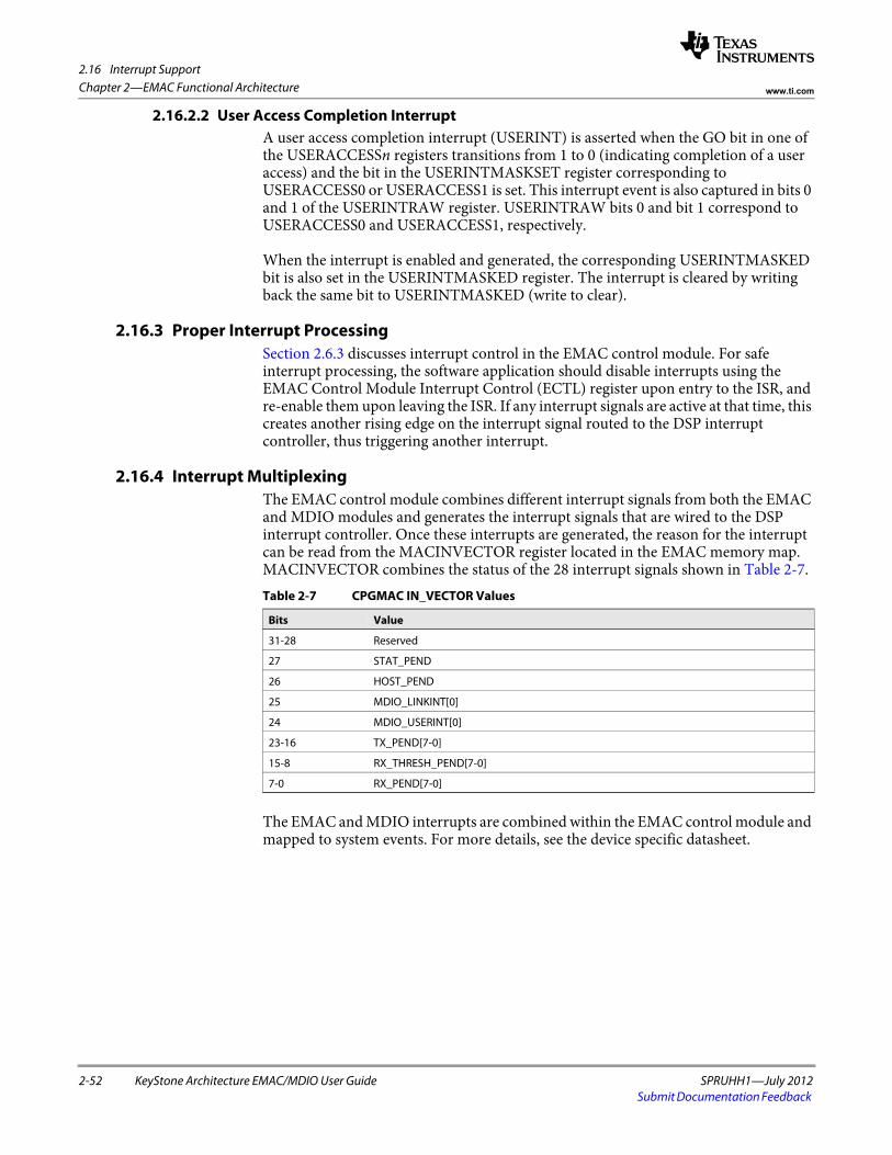
2.16 Interrupt Support
2-52 KeyStone Architecture EMAC/MDIO User Guide SPRUHH1—July 2012Submit Documentation Feedback
Chapter 2—EMAC Functional Architecture www.ti.com
2.16.2.2 User Access Completion InterruptA user access completion interrupt (USERINT) is asserted when the GO bit in one of the USERACCESSn registers transitions from 1 to 0 (indicating completion of a user access) and the bit in the USERINTMASKSET register corresponding to USERACCESS0 or USERACCESS1 is set. This interrupt event is also captured in bits 0 and 1 of the USERINTRAW register. USERINTRAW bits 0 and bit 1 correspond to USERACCESS0 and USERACCESS1, respectively.
When the interrupt is enabled and generated, the corresponding USERINTMASKED bit is also set in the USERINTMASKED register. The interrupt is cleared by writing back the same bit to USERINTMASKED (write to clear).
2.16.3 Proper Interrupt ProcessingSection 2.6.3 discusses interrupt control in the EMAC control module. For safe interrupt processing, the software application should disable interrupts using the EMAC Control Module Interrupt Control (ECTL) register upon entry to the ISR, and re-enable them upon leaving the ISR. If any interrupt signals are active at that time, this creates another rising edge on the interrupt signal routed to the DSP interrupt controller, thus triggering another interrupt.
2.16.4 Interrupt MultiplexingThe EMAC control module combines different interrupt signals from both the EMAC and MDIO modules and generates the interrupt signals that are wired to the DSP interrupt controller. Once these interrupts are generated, the reason for the interrupt can be read from the MACINVECTOR register located in the EMAC memory map. MACINVECTOR combines the status of the 28 interrupt signals shown in Table 2-7.
The EMAC and MDIO interrupts are combined within the EMAC control module and mapped to system events. For more details, see the device specific datasheet.
Table 2-7 CPGMAC IN_VECTOR Values
Bits Value
31-28 Reserved
27 STAT_PEND
26 HOST_PEND
25 MDIO_LINKINT[0]
24 MDIO_USERINT[0]
23-16 TX_PEND[7-0]
15-8 RX_THRESH_PEND[7-0]
7-0 RX_PEND[7-0]
2.17 Pulse Interrupts
SPRUHH1—July 2012 KeyStone Architecture EMAC/MDIO User Guide 2-53Submit Documentation Feedback
Chapter 2—EMAC Functional Architecturewww.ti.com
2.17 Pulse InterruptsThe following pulse interrupts are generated by the CPGMAC:
2.17.1 Pulse Interrupt DescriptionThis section describes the EMAC pulse interrupts.
2.17.1.1 Transmit Packet Completion InterruptsThe transmit DMA controller has eight channels with each channel having a corresponding pulse interrupt (TX_PULSE [7-0]). Each of the eight channel pulse interrupts may be individually enabled by setting to one the appropriate bit in the TXINTMASKSET register. Each of the eight channel interrupts may be individually disabled by clearing to zero the appropriate bit in the TXINTMASKCLEAR register. When each EMAC packet DMA transmission is complete (not the complete packet transmission on the wire), the CPGMAC issues a single interrupt pulse. No acknowledgement from the host is required.
2.17.1.2 Receive Packet Completion InterruptsThe receive DMA controller has eight channels with each channel having a corresponding pulse interrupt (RX_PULSE [7-0]). Each of the eight channel interrupts may be individually enabled by setting to one the appropriate bit in the RXINTMASKSET register. Each of the eight channel interrupts may be individually disabled by clearing to zero the appropriate bit in the RXINTMASKCLEAR register. When a packet DMA reception is complete, the CPGMAC issues a single pulse interrupt. No acknowledgement from the host is required.
2.17.1.3 EMAC Event ConnectivityThe EMAC events connect to the DSP through the chip interrupt controller. See the device specific datasheet for the system event numbers.
Table 2-8 Pulse Interrupts
Interrupt Description
TX_PULSE[7-0] Transmit packet completion interrupts for transmit channels 7 to 0.
RX_PULSE[7-0] Receive packet completion interrupts for receive channels 7 to 0.
2.18 SGMII Interface
2-54 KeyStone Architecture EMAC/MDIO User Guide SPRUHH1—July 2012Submit Documentation Feedback
Chapter 2—EMAC Functional Architecture www.ti.com
2.18 SGMII InterfaceThe EMAC supports the Gigabit Media Independent Interface, which is connected to the external device through Serial Gigabit Media Independent Interface (SGM II) with SerDes. The following sections discuss the operation of this interface.
2.18.1 Receive InterfaceThe CPSGMII receive (RX) interface converts the encoded receive input (RX_ENC) from the SERDES into the required CPGMAC GMII signals.
2.18.2 Transmit InterfaceThe CPSGMII transmit (TX) interface converts the CPGMAC GMII input data in to the required encoded transmit outputs (TX_ENC). The CPGMAC does not source the transmit error signal. Any transmit frame from the CPGMAC with an error (ie. Underrun) will be indicated as an error by an error CRC. Transmit error is assumed to be zero at all times and is not input to the CPSGMII module. In 10/100 mode, the GMII_MTXD[7-0] data bus uses only the lower nibble. Any packet in transmission from the CPGMAC while the link signal is de-asserted will be ignored. Only packets that begin after the rising edge of link will be transferred.
2.18.3 LoopbackThe loopback bit in the CONTROL register enables the SGMII module to operate in loopback mode. When loopback is asserted, transmit is internally connected to receive within the SGMII module. This is digital loopback (before the SERDES) from the CPSGMII transmit to the CPSGMII receive. The transmit clock TX_CLK input is used for transmit and receive clocking when loopback is asserted. The RT_SOFT_RESET bit in the SOFT_RESET register is used to reset the transmit and receive logic when switching to and from loopback mode. The sequence for entering or exiting the loopback mode is shown below:
Step - ActionProcedure 2-6 Loopback
1 Clear to zero the MR_AN_ENABLE bit in the CONTROL register.
2 Write to one the RT_SOFT_RESET bit in the SOFT_RESET register.
3 Write to one the LOOPBACK bit in the CONTROL register.
4 Write to zero the RT_SOFT_RESET bit in the SOFT_RESET register.
End of Procedure 2-6
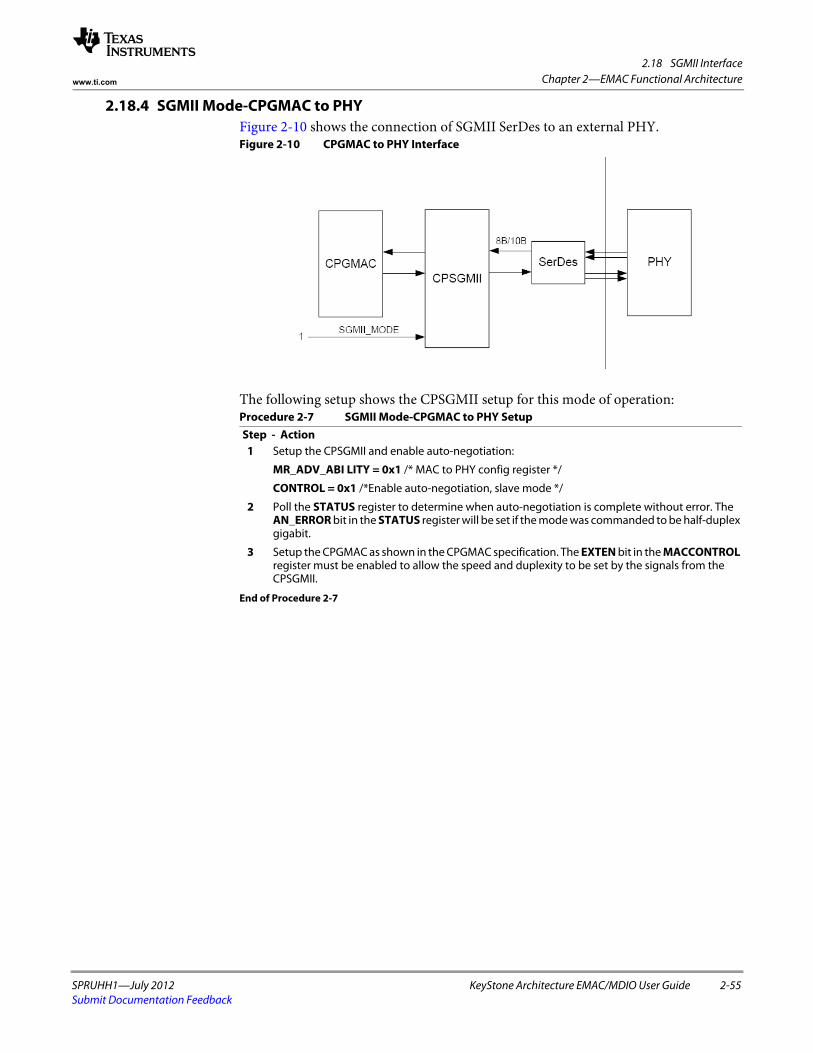
2.18 SGMII Interface
SPRUHH1—July 2012 KeyStone Architecture EMAC/MDIO User Guide 2-55Submit Documentation Feedback
Chapter 2—EMAC Functional Architecturewww.ti.com
2.18.4 SGMII Mode-CPGMAC to PHYFigure 2-10 shows the connection of SGMII SerDes to an external PHY. Figure 2-10 CPGMAC to PHY Interface
The following setup shows the CPSGMII setup for this mode of operation:
Step - ActionProcedure 2-7 SGMII Mode-CPGMAC to PHY Setup
1 Setup the CPSGMII and enable auto-negotiation:
MR_ADV_ABI LITY = 0x1 /* MAC to PHY config register */
CONTROL = 0x1 /*Enable auto-negotiation, slave mode */
2 Poll the STATUS register to determine when auto-negotiation is complete without error. The AN_ERROR bit in the STATUS register will be set if the mode was commanded to be half-duplex gigabit.
3 Setup the CPGMAC as shown in the CPGMAC specification. The EXTEN bit in the MACCONTROL register must be enabled to allow the speed and duplexity to be set by the signals from the CPSGMII.
End of Procedure 2-7
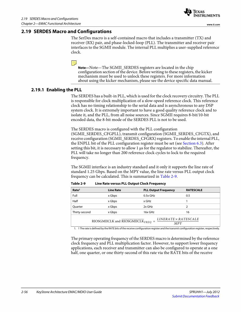
2.19 SERDES Macro and Configurations
2-56 KeyStone Architecture EMAC/MDIO User Guide SPRUHH1—July 2012Submit Documentation Feedback
Chapter 2—EMAC Functional Architecture www.ti.com
2.19 SERDES Macro and ConfigurationsThe SerDes macro is a self-contained macro that includes a transmitter (TX) and receiver (RX) pair, and phase-locked-loop (PLL). The transmitter and receiver pair interfaces to the SGMII module. The internal PLL multiplies a user-supplied reference clock.
Note—Note—The SGMII_SERDES registers are located in the chip configuration section of the device. Before writing to these registers, the kicker mechanism must be used to unlock these registers. For more information about using the kicker mechanism, please see the device specific data manual.
2.19.1 Enabling the PLLThe SERDES has a built-in PLL, which is used for the clock recovery circuitry. The PLL is responsible for clock multiplication of a slow-speed reference clock. This reference clock has no timing relationship to the serial data and is asynchronous to any DSP system clock. It is extremely important to have a good quality reference clock and to isolate it, and the PLL, from all noise sources. Since SGMII requires 8-bit/10-bit encoded data, the 8-bit mode of the SERDES PLL is not to be used.
The SERDES macro is configured with the PLL configuration (SGMII_SERDES_CFGPLL), transmit configuration (SGMII_SERDES_CFGTX), and receive configuration (SGMII_SERDES_CFGRX) registers. To enable the internal PLL, the ENPLL bit of the PLL configuration register must be set (see Section 6.3). After setting this bit, it is necessary to allow 1 μs for the regulator to stabilize. Thereafter, the PLL will take no longer than 200 reference clock cycles to lock to the required frequency.
The SGMII interface is an industry standard and it only it supports the line rate of standard 1.25 Gbps. Based on the MPY value, the line rate versus PLL output clock frequency can be calculated. This is summarized in Table 2-9.
The primary operating frequency of the SERDES macro is determined by the reference clock frequency and PLL multiplication factor. However, to support lower frequency applications, each receiver and transmitter can also be configured to operate at a one half, one quarter, or one thirty-second of this rate via the RATE bits of the receive
Table 2-9 Line Rate versus PLL Output Clock Frequency
Rate1
1. 1 The rate is defined by the RATE bits of the receive configuration register and the transmit configuration register, respectively.
Line Rate PLL Output Frequency RATESCALE
Full x Gbps 0.5x GHz 0.5
Half x Gbps x GHz 1
Quarter x Gbps 2x GHz 2
Thirty-second x Gbps 16x GHz 16
RIOSGMIICLK and RIOSGMIICLKFREQLINERATE RATESCALE×
MPY------------------------------------------------------------------=
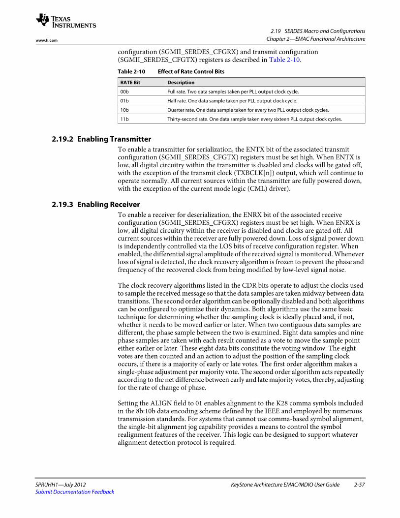
2.19 SERDES Macro and Configurations
SPRUHH1—July 2012 KeyStone Architecture EMAC/MDIO User Guide 2-57Submit Documentation Feedback
Chapter 2—EMAC Functional Architecturewww.ti.com
configuration (SGMII_SERDES_CFGRX) and transmit configuration (SGMII_SERDES_CFGTX) registers as described in Table 2-10.
2.19.2 Enabling TransmitterTo enable a transmitter for serialization, the ENTX bit of the associated transmit configuration (SGMII_SERDES_CFGTX) registers must be set high. When ENTX is low, all digital circuitry within the transmitter is disabled and clocks will be gated off, with the exception of the transmit clock (TXBCLK[n]) output, which will continue to operate normally. All current sources within the transmitter are fully powered down, with the exception of the current mode logic (CML) driver).
2.19.3 Enabling ReceiverTo enable a receiver for deserialization, the ENRX bit of the associated receive configuration (SGMII_SERDES_CFGRX) registers must be set high. When ENRX is low, all digital circuitry within the receiver is disabled and clocks are gated off. All current sources within the receiver are fully powered down. Loss of signal power down is independently controlled via the LOS bits of receive configuration register. When enabled, the differential signal amplitude of the received signal is monitored. Whenever loss of signal is detected, the clock recovery algorithm is frozen to prevent the phase and frequency of the recovered clock from being modified by low-level signal noise.
The clock recovery algorithms listed in the CDR bits operate to adjust the clocks used to sample the received message so that the data samples are taken midway between data transitions. The second order algorithm can be optionally disabled and both algorithms can be configured to optimize their dynamics. Both algorithms use the same basic technique for determining whether the sampling clock is ideally placed and, if not, whether it needs to be moved earlier or later. When two contiguous data samples are different, the phase sample between the two is examined. Eight data samples and nine phase samples are taken with each result counted as a vote to move the sample point either earlier or later. These eight data bits constitute the voting window. The eight votes are then counted and an action to adjust the position of the sampling clock occurs, if there is a majority of early or late votes. The first order algorithm makes a single-phase adjustment per majority vote. The second order algorithm acts repeatedly according to the net difference between early and late majority votes, thereby, adjusting for the rate of change of phase.
Setting the ALIGN field to 01 enables alignment to the K28 comma symbols included in the 8b:10b data encoding scheme defined by the IEEE and employed by numerous transmission standards. For systems that cannot use comma-based symbol alignment, the single-bit alignment jog capability provides a means to control the symbol realignment features of the receiver. This logic can be designed to support whatever alignment detection protocol is required.
Table 2-10 Effect of Rate Control Bits
RATE Bit Description
00b Full rate. Two data samples taken per PLL output clock cycle.
01b Half rate. One data sample taken per PLL output clock cycle.
10b Quarter rate. One data sample taken for every two PLL output clock cycles.
11b Thirty-second rate. One data sample taken every sixteen PLL output clock cycles.
2.19 SERDES Macro and Configurations
2-58 KeyStone Architecture EMAC/MDIO User Guide SPRUHH1—July 2012Submit Documentation Feedback
Chapter 2—EMAC Functional Architecture www.ti.com
The EQ bits allow for enabling and configuring the adaptive equalizer incorporated in all of the receive channels, which can compensate for channel insertion loss by attenuating the low-frequency components with respect to the high-frequency components of the signal, thereby, reducing inter-symbol interference.
Above the zero frequency, the gain increases at 6 dB/octave until it reaches the high-frequency gain. When enabled, the receiver equalization logic analyzes data patterns and transition times to determine whether the low-frequency gain of the equalizer should be increased or decreased. For the fully adaptive setting (EQ = 0001), if the low frequency gain reaches the minimum value, the zero frequency is then reduced. Likewise, if it reaches the maximum value, the zero frequency is then increased. This decision logic is implemented as a voting algorithm with a relatively long analysis interval. The slow time constant that results reduces the probability of incorrect decisions but allows the equalizer to compensate for the relatively stable response of the channel.
• No adaptive equalization. The equalizer provides a flat response at the maximum gain. This setting may be appropriate if jitter at the receiver occurs predominantly as a result of crosstalk rather than frequency-dependent loss.
• Fully adaptive equalization. Both the low frequency gain and zero position of the equalizer are determined algorithmically by analyzing the data patterns and transition positions in the received data. This setting should be used for most applications.
• Partially adaptive equalization. The low-frequency gain of the equalizer is determined algorithmically by analyzing the data patterns and transition positions in the received data. The zero position is fixed in one of eight zero positions. For any given application, the optimal setting is a function of the loss characteristics of the channel and the spectral density of the signal as well as the data rate, which means it is not possible to identify the best setting by data rate alone. Although, generally speaking, the lower the line rate, the lower the zero frequency that is required.
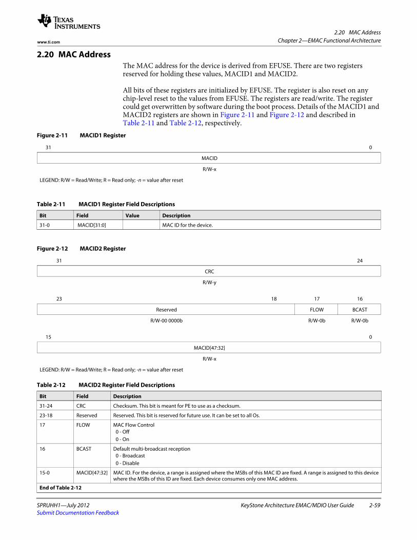
2.20 MAC Address
SPRUHH1—July 2012 KeyStone Architecture EMAC/MDIO User Guide 2-59Submit Documentation Feedback
Chapter 2—EMAC Functional Architecturewww.ti.com
2.20 MAC AddressThe MAC address for the device is derived from EFUSE. There are two registers reserved for holding these values, MACID1 and MACID2.
All bits of these registers are initialized by EFUSE. The register is also reset on any chip-level reset to the values from EFUSE. The registers are read/write. The register could get overwritten by software during the boot process. Details of the MACID1 and MACID2 registers are shown in Figure 2-11 and Figure 2-12 and described in Table 2-11 and Table 2-12, respectively.
Figure 2-11 MACID1 Register
31 0
MACID
R/W-x
LEGEND: R/W = Read/Write; R = Read only; -n = value after reset
Table 2-11 MACID1 Register Field Descriptions
Bit Field Value Description
31-0 MACID[31:0] MAC ID for the device.
Figure 2-12 MACID2 Register
31 24
CRC
R/W-y
23 18 17 16
Reserved FLOW BCAST
R/W-00 0000b R/W-0b R/W-0b
15 0
MACID[47:32]
R/W-x
LEGEND: R/W = Read/Write; R = Read only; -n = value after reset
Table 2-12 MACID2 Register Field Descriptions
Bit Field Description
31-24 CRC Checksum. This bit is meant for PE to use as a checksum.
23-18 Reserved Reserved. This bit is reserved for future use. It can be set to all Os.
17 FLOW MAC Flow Control 0 - Off 0 - On
16 BCAST Default multi-broadcast reception 0 - Broadcast0 - Disable
15-0 MACID[47:32] MAC ID. For the device, a range is assigned where the MSBs of this MAC ID are fixed. A range is assigned to this device where the MSBs of this ID are fixed. Each device consumes only one MAC address.
End of Table 2-12
2.21 Power Management
2-60 KeyStone Architecture EMAC/MDIO User Guide SPRUHH1—July 2012Submit Documentation Feedback
Chapter 2—EMAC Functional Architecture www.ti.com
2.21 Power ManagementThe Powersaver module integrated in this device allows the clock going to different peripherals to be shut down when that peripheral is not being used. For more information on the power conservation modes available for the EMAC/MDIO peripheral, see the data manual for your device.
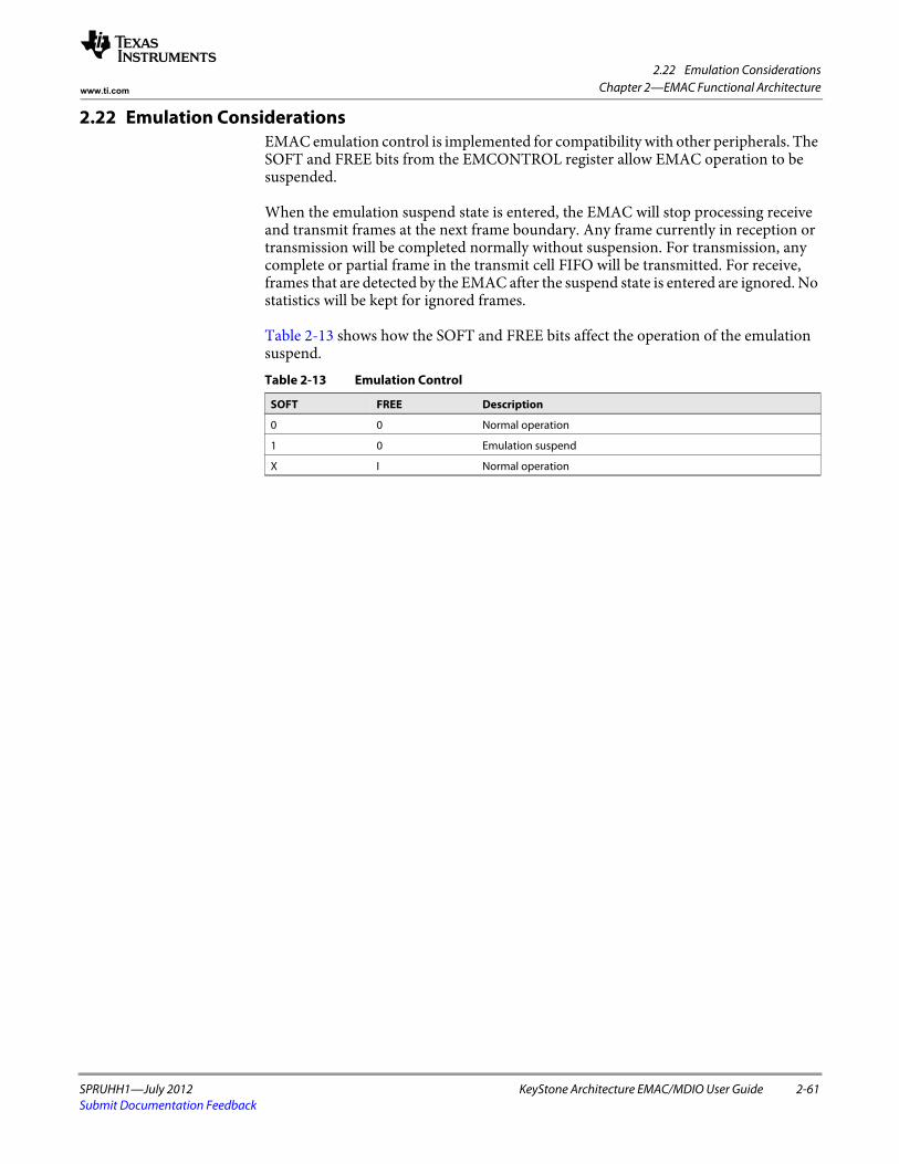
2.22 Emulation Considerations
SPRUHH1—July 2012 KeyStone Architecture EMAC/MDIO User Guide 2-61Submit Documentation Feedback
Chapter 2—EMAC Functional Architecturewww.ti.com
2.22 Emulation ConsiderationsEMAC emulation control is implemented for compatibility with other peripherals. The SOFT and FREE bits from the EMCONTROL register allow EMAC operation to be suspended.
When the emulation suspend state is entered, the EMAC will stop processing receive and transmit frames at the next frame boundary. Any frame currently in reception or transmission will be completed normally without suspension. For transmission, any complete or partial frame in the transmit cell FIFO will be transmitted. For receive, frames that are detected by the EMAC after the suspend state is entered are ignored. No statistics will be kept for ignored frames.
Table 2-13 shows how the SOFT and FREE bits affect the operation of the emulation suspend. Table 2-13 Emulation Control
SOFT FREE Description
0 0 Normal operation
1 0 Emulation suspend
X I Normal operation

2.22 Emulation Considerations
2-62 KeyStone Architecture EMAC/MDIO User Guide SPRUHH1—July 2012Submit Documentation Feedback
Chapter 2—EMAC Functional Architecture www.ti.com
SPRUHH1—July 2012 KeyStone Architecture EMAC/MDIO User Guide 3-1Submit Documentation Feedback
Chapter 3
EMAC Interrupt Controller Registers
3.1 "Introduction" on page 3-2 3.2 "Identification and Version Register (IDVER)" on page 3-3 3.3 "Software Reset Register (SOFT_RESET)" on page 3-4 3.4 "Emulation Control Register (EM_CONTROL)" on page 3-5 3.5 "Interrupt Control Register (INT_CONTROL)" on page 3-6 3.6 "Receive Threshold Enable Register (Cn_RX_THRESH_EN)" on page 3-7 3.7 "Receive Enable Register (Cn_RX_EN)" on page 3-8 3.8 "Transmit Enable Register (Cn_TX_EN)" on page 3-9 3.9 "Miscellaneous Enable Register (Cn_MISC_EN)" on page 3-10
3.10 "Receive Threshold Status Register (Cn_RX_THRESH_STAT)" on page 3-11 3.11 "Receive Status Register (Cn_RX_STAT)" on page 3-12 3.12 "Transmit Status Register (Cn_TX_STAT)" on page 3-13 3.13 "Miscellaneous Status Register (Cn_MISC_STAT)" on page 3-14 3.14 "Receive Interrupts per Millisecond Register (Cn_RX_IMAX)" on page 3-15 3.15 "Transmit Interrupts per Millisecond Register (Cn_TX_IMAX)" on page 3-16
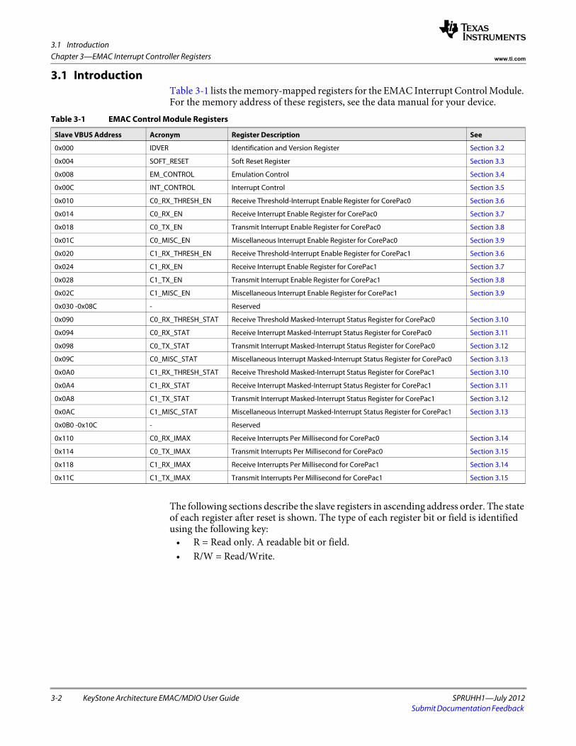
3.1 Introduction
3-2 KeyStone Architecture EMAC/MDIO User Guide SPRUHH1—July 2012Submit Documentation Feedback
Chapter 3—EMAC Interrupt Controller Registers www.ti.com
3.1 IntroductionTable 3-1 lists the memory-mapped registers for the EMAC Interrupt Control Module. For the memory address of these registers, see the data manual for your device.
The following sections describe the slave registers in ascending address order. The state of each register after reset is shown. The type of each register bit or field is identified using the following key:
• R = Read only. A readable bit or field. • R/W = Read/Write.
Table 3-1 EMAC Control Module Registers
Slave VBUS Address Acronym Register Description See
0x000 IDVER Identification and Version Register Section 3.2
0x004 SOFT_RESET Soft Reset Register Section 3.3
0x008 EM_CONTROL Emulation Control Section 3.4
0x00C INT_CONTROL Interrupt Control Section 3.5
0x010 C0_RX_THRESH_EN Receive Threshold-Interrupt Enable Register for CorePac0 Section 3.6
0x014 C0_RX_EN Receive Interrupt Enable Register for CorePac0 Section 3.7
0x018 C0_TX_EN Transmit Interrupt Enable Register for CorePac0 Section 3.8
0x01C C0_MISC_EN Miscellaneous Interrupt Enable Register for CorePac0 Section 3.9
0x020 C1_RX_THRESH_EN Receive Threshold-Interrupt Enable Register for CorePac1 Section 3.6
0x024 C1_RX_EN Receive Interrupt Enable Register for CorePac1 Section 3.7
0x028 C1_TX_EN Transmit Interrupt Enable Register for CorePac1 Section 3.8
0x02C C1_MISC_EN Miscellaneous Interrupt Enable Register for CorePac1 Section 3.9
0x030 -0x08C - Reserved
0x090 C0_RX_THRESH_STAT Receive Threshold Masked-Interrupt Status Register for CorePac0 Section 3.10
0x094 C0_RX_STAT Receive Interrupt Masked-Interrupt Status Register for CorePac0 Section 3.11
0x098 C0_TX_STAT Transmit Interrupt Masked-Interrupt Status Register for CorePac0 Section 3.12
0x09C C0_MISC_STAT Miscellaneous Interrupt Masked-Interrupt Status Register for CorePac0 Section 3.13
0x0A0 C1_RX_THRESH_STAT Receive Threshold Masked-Interrupt Status Register for CorePac1 Section 3.10
0x0A4 C1_RX_STAT Receive Interrupt Masked-Interrupt Status Register for CorePac1 Section 3.11
0x0A8 C1_TX_STAT Transmit Interrupt Masked-Interrupt Status Register for CorePac1 Section 3.12
0x0AC C1_MISC_STAT Miscellaneous Interrupt Masked-Interrupt Status Register for CorePac1 Section 3.13
0x0B0 -0x10C - Reserved
0x110 C0_RX_IMAX Receive Interrupts Per Millisecond for CorePac0 Section 3.14
0x114 C0_TX_IMAX Transmit Interrupts Per Millisecond for CorePac0 Section 3.15
0x118 C1_RX_IMAX Receive Interrupts Per Millisecond for CorePac1 Section 3.14
0x11C C1_TX_IMAX Transmit Interrupts Per Millisecond for CorePac1 Section 3.15
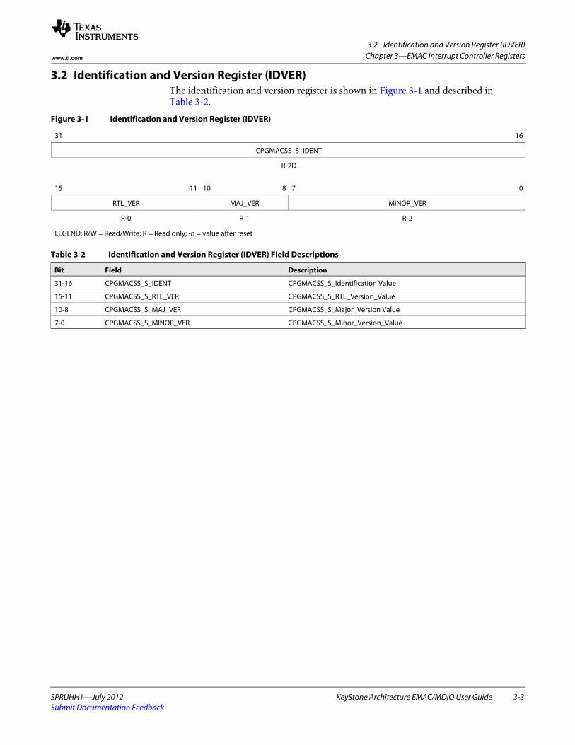
3.2 Identification and Version Register (IDVER)
SPRUHH1—July 2012 KeyStone Architecture EMAC/MDIO User Guide 3-3Submit Documentation Feedback
Chapter 3—EMAC Interrupt Controller Registerswww.ti.com
3.2 Identification and Version Register (IDVER)The identification and version register is shown in Figure 3-1 and described in Table 3-2.
Figure 3-1 Identification and Version Register (IDVER)
31 16
CPGMACSS_S_IDENT
R-2D spacer
15 11 10 8 7 0
RTL_VER MAJ_VER MINOR_VER
R-0 R-1 R-2
LEGEND: R/W = Read/Write; R = Read only; -n = value after reset
Table 3-2 Identification and Version Register (IDVER) Field Descriptions
Bit Field Description
31-16 CPGMACSS_S_IDENT CPGMACSS_S_Identification Value
15-11 CPGMACSS_S_RTL_VER CPGMACSS_S_RTL_Version_Value
10-8 CPGMACSS_S_MAJ_VER CPGMACSS_S_Major_Version Value
7-0 CPGMACSS_S_MINOR_VER CPGMACSS_S_Minor_Version_Value
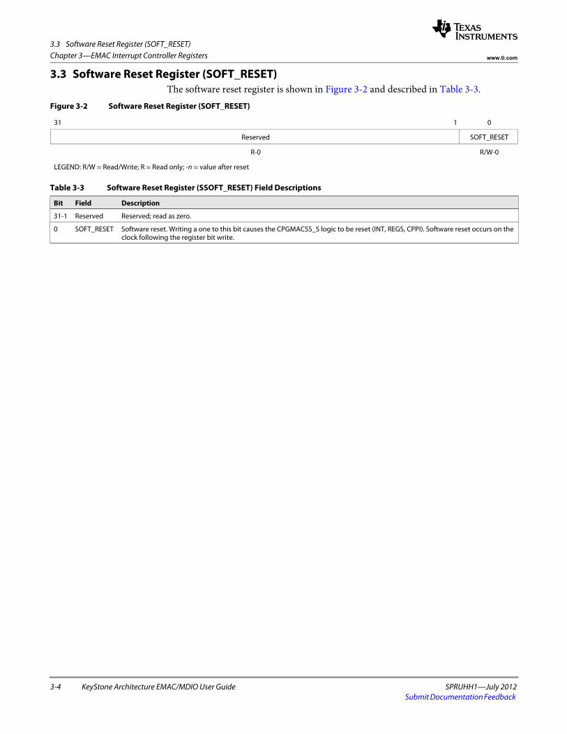
3.3 Software Reset Register (SOFT_RESET)
3-4 KeyStone Architecture EMAC/MDIO User Guide SPRUHH1—July 2012Submit Documentation Feedback
Chapter 3—EMAC Interrupt Controller Registers www.ti.com
3.3 Software Reset Register (SOFT_RESET)The software reset register is shown in Figure 3-2 and described in Table 3-3.
Figure 3-2 Software Reset Register (SOFT_RESET)
31 1 0
Reserved SOFT_RESET
R-0 R/W-0
LEGEND: R/W = Read/Write; R = Read only; -n = value after reset
Table 3-3 Software Reset Register (SSOFT_RESET) Field Descriptions
Bit Field Description
31-1 Reserved Reserved; read as zero.
0 SOFT_RESET Software reset. Writing a one to this bit causes the CPGMACSS_S logic to be reset (INT, REGS, CPPI). Software reset occurs on the clock following the register bit write.
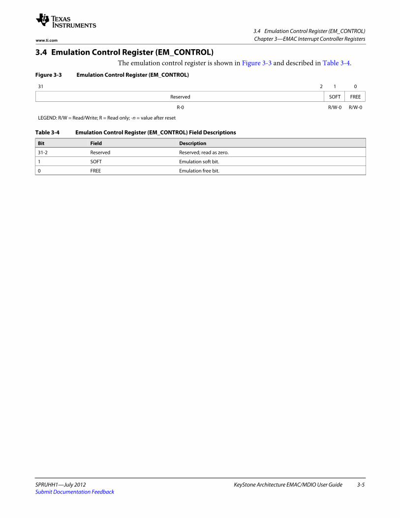
3.4 Emulation Control Register (EM_CONTROL)
SPRUHH1—July 2012 KeyStone Architecture EMAC/MDIO User Guide 3-5Submit Documentation Feedback
Chapter 3—EMAC Interrupt Controller Registerswww.ti.com
3.4 Emulation Control Register (EM_CONTROL)The emulation control register is shown in Figure 3-3 and described in Table 3-4.
Figure 3-3 Emulation Control Register (EM_CONTROL)
31 2 1 0
Reserved SOFT FREE
R-0 R/W-0 R/W-0
LEGEND: R/W = Read/Write; R = Read only; -n = value after reset
Table 3-4 Emulation Control Register (EM_CONTROL) Field Descriptions
Bit Field Description
31-2 Reserved Reserved; read as zero.
1 SOFT Emulation soft bit.
0 FREE Emulation free bit.
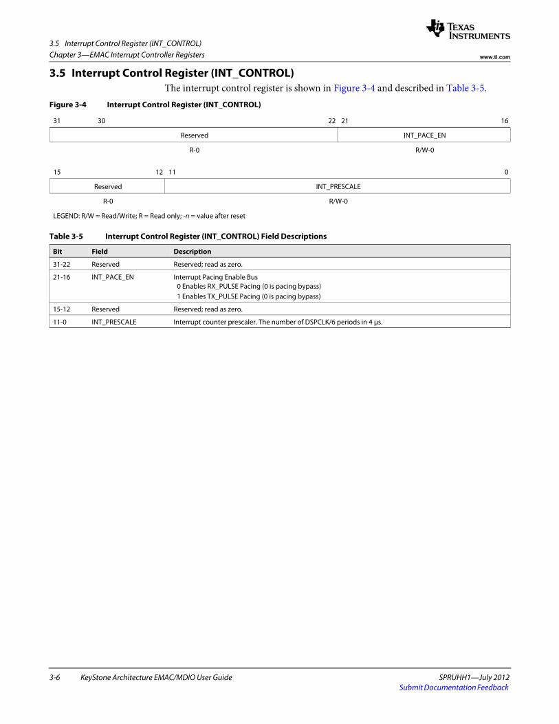
3.5 Interrupt Control Register (INT_CONTROL)
3-6 KeyStone Architecture EMAC/MDIO User Guide SPRUHH1—July 2012Submit Documentation Feedback
Chapter 3—EMAC Interrupt Controller Registers www.ti.com
3.5 Interrupt Control Register (INT_CONTROL)The interrupt control register is shown in Figure 3-4 and described in Table 3-5.
Figure 3-4 Interrupt Control Register (INT_CONTROL)
31 30 22 21 16
Reserved INT_PACE_EN
R-0 R/W-0spacer
15 12 11 0
Reserved INT_PRESCALE
R-0 R/W-0
LEGEND: R/W = Read/Write; R = Read only; -n = value after reset
Table 3-5 Interrupt Control Register (INT_CONTROL) Field Descriptions
Bit Field Description
31-22 Reserved Reserved; read as zero.
21-16 INT_PACE_EN Interrupt Pacing Enable Bus 0 Enables RX_PULSE Pacing (0 is pacing bypass) 1 Enables TX_PULSE Pacing (0 is pacing bypass)
15-12 Reserved Reserved; read as zero.
11-0 INT_PRESCALE Interrupt counter prescaler. The number of DSPCLK/6 periods in 4 μs.
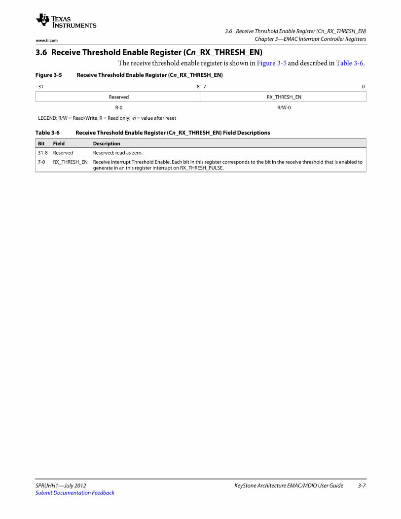
3.6 Receive Threshold Enable Register (Cn_RX_THRESH_EN)
SPRUHH1—July 2012 KeyStone Architecture EMAC/MDIO User Guide 3-7Submit Documentation Feedback
Chapter 3—EMAC Interrupt Controller Registerswww.ti.com
3.6 Receive Threshold Enable Register (Cn_RX_THRESH_EN)The receive threshold enable register is shown in Figure 3-5 and described in Table 3-6.
Figure 3-5 Receive Threshold Enable Register (Cn_RX_THRESH_EN)
31 8 7 0
Reserved RX_THRESH_EN
R-0 R/W-0
LEGEND: R/W = Read/Write; R = Read only; -n = value after reset
Table 3-6 Receive Threshold Enable Register (Cn_RX_THRESH_EN) Field Descriptions
Bit Field Description
31-8 Reserved Reserved; read as zero.
7-0 RX_THRESH_EN Receive interrupt Threshold Enable. Each bit in this register corresponds to the bit in the receive threshold that is enabled to generate in an this register interrupt on RX_THRESH_PULSE.
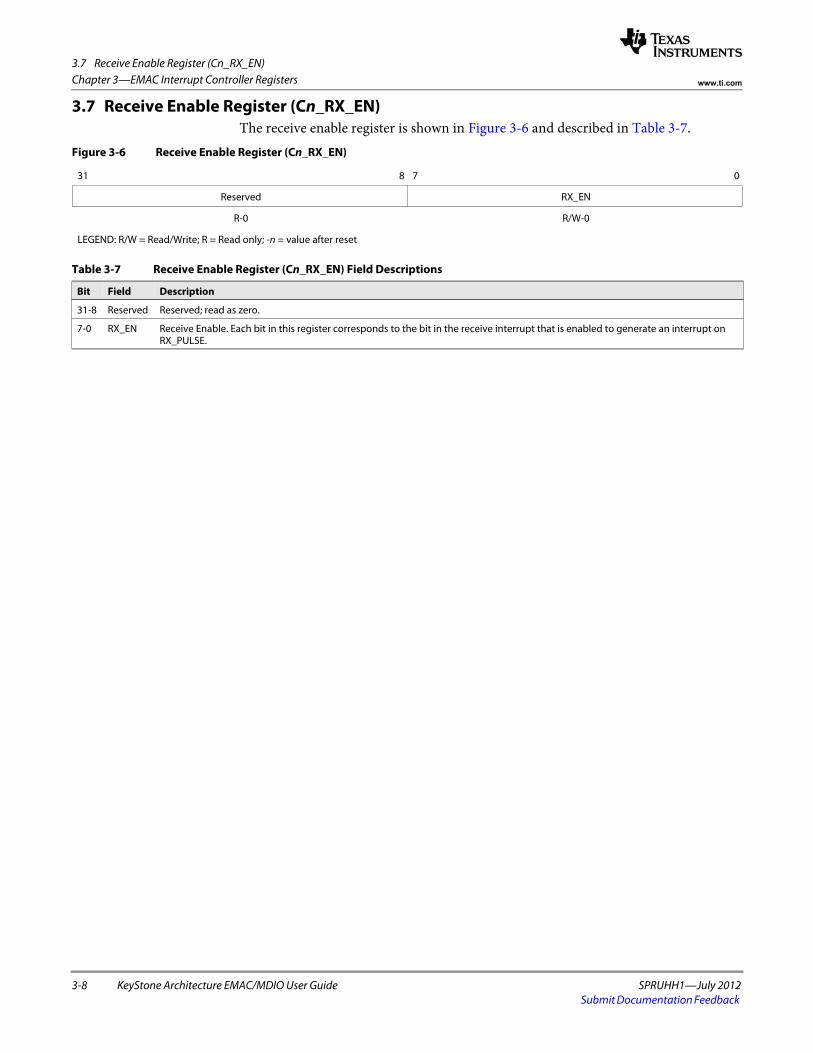
3.7 Receive Enable Register (Cn_RX_EN)
3-8 KeyStone Architecture EMAC/MDIO User Guide SPRUHH1—July 2012Submit Documentation Feedback
Chapter 3—EMAC Interrupt Controller Registers www.ti.com
3.7 Receive Enable Register (Cn_RX_EN)The receive enable register is shown in Figure 3-6 and described in Table 3-7.
Figure 3-6 Receive Enable Register (Cn_RX_EN)
31 8 7 0
Reserved RX_EN
R-0 R/W-0
LEGEND: R/W = Read/Write; R = Read only; -n = value after reset
Table 3-7 Receive Enable Register (Cn_RX_EN) Field Descriptions
Bit Field Description
31-8 Reserved Reserved; read as zero.
7-0 RX_EN Receive Enable. Each bit in this register corresponds to the bit in the receive interrupt that is enabled to generate an interrupt on RX_PULSE.

3.8 Transmit Enable Register (Cn_TX_EN)
SPRUHH1—July 2012 KeyStone Architecture EMAC/MDIO User Guide 3-9Submit Documentation Feedback
Chapter 3—EMAC Interrupt Controller Registerswww.ti.com
3.8 Transmit Enable Register (Cn_TX_EN)The transmit enable register is shown in Figure 3-7 and described in Table 3-8.
Figure 3-7 Transmit Enable Register (Cn_TX_EN)
31 8 7 0
Reserved TX_EN
R-0 R/W-0
LEGEND: R/W = Read/Write; R = Read only; -n = value after reset
Table 3-8 Transmit Enable Register (Cn_TX_EN) Field Descriptions
Bit Field Description
31-8 Reserved Reserved; read as zero.
7-0 TX_EN Transmit Enable. Each bit in this register corresponds to the bit in the receive interrupt that is enabled to generate an interrupt on TX_PULSE.
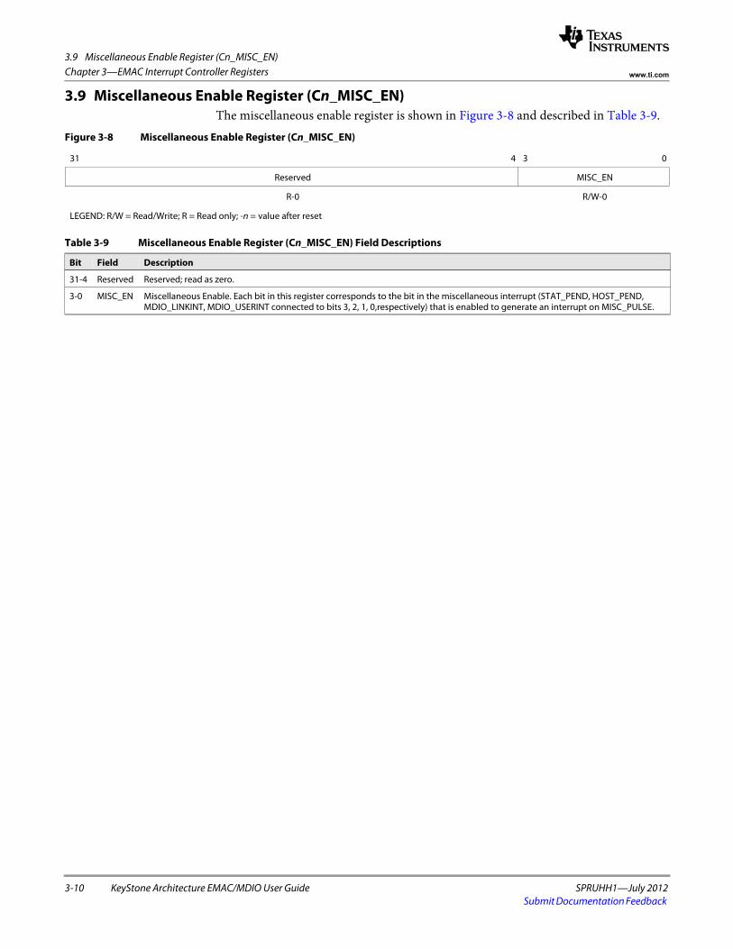
3.9 Miscellaneous Enable Register (Cn_MISC_EN)
3-10 KeyStone Architecture EMAC/MDIO User Guide SPRUHH1—July 2012Submit Documentation Feedback
Chapter 3—EMAC Interrupt Controller Registers www.ti.com
3.9 Miscellaneous Enable Register (Cn_MISC_EN)The miscellaneous enable register is shown in Figure 3-8 and described in Table 3-9.
Figure 3-8 Miscellaneous Enable Register (Cn_MISC_EN)
31 4 3 0
Reserved MISC_EN
R-0 R/W-0
LEGEND: R/W = Read/Write; R = Read only; -n = value after reset
Table 3-9 Miscellaneous Enable Register (Cn_MISC_EN) Field Descriptions
Bit Field Description
31-4 Reserved Reserved; read as zero.
3-0 MISC_EN Miscellaneous Enable. Each bit in this register corresponds to the bit in the miscellaneous interrupt (STAT_PEND, HOST_PEND, MDIO_LINKINT, MDIO_USERINT connected to bits 3, 2, 1, 0,respectively) that is enabled to generate an interrupt on MISC_PULSE.
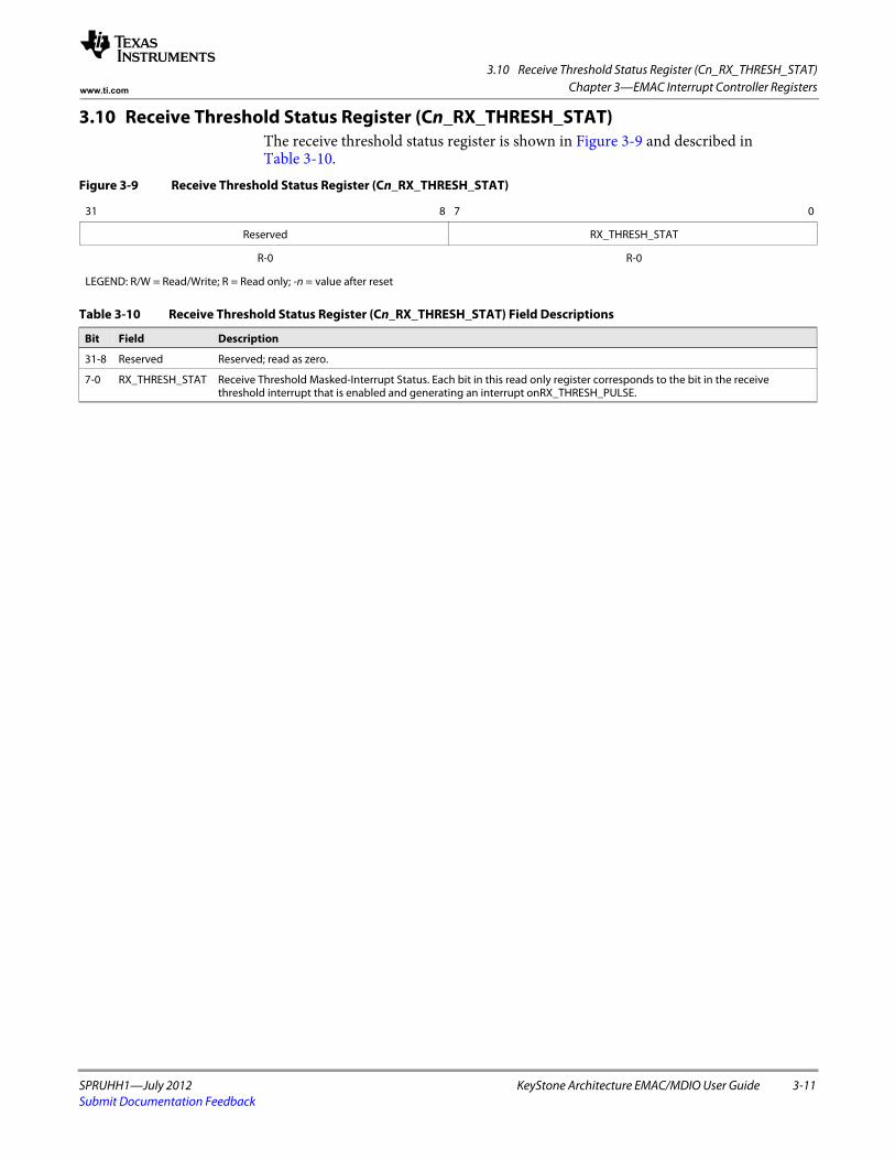
3.10 Receive Threshold Status Register (Cn_RX_THRESH_STAT)
SPRUHH1—July 2012 KeyStone Architecture EMAC/MDIO User Guide 3-11Submit Documentation Feedback
Chapter 3—EMAC Interrupt Controller Registerswww.ti.com
3.10 Receive Threshold Status Register (Cn_RX_THRESH_STAT)The receive threshold status register is shown in Figure 3-9 and described in Table 3-10.
Figure 3-9 Receive Threshold Status Register (Cn_RX_THRESH_STAT)
31 8 7 0
Reserved RX_THRESH_STAT
R-0 R-0
LEGEND: R/W = Read/Write; R = Read only; -n = value after reset
Table 3-10 Receive Threshold Status Register (Cn_RX_THRESH_STAT) Field Descriptions
Bit Field Description
31-8 Reserved Reserved; read as zero.
7-0 RX_THRESH_STAT Receive Threshold Masked-Interrupt Status. Each bit in this read only register corresponds to the bit in the receive threshold interrupt that is enabled and generating an interrupt onRX_THRESH_PULSE.
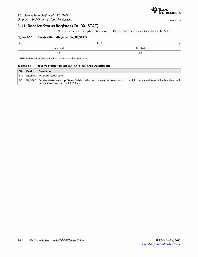
3.11 Receive Status Register (Cn_RX_STAT)
3-12 KeyStone Architecture EMAC/MDIO User Guide SPRUHH1—July 2012Submit Documentation Feedback
Chapter 3—EMAC Interrupt Controller Registers www.ti.com
3.11 Receive Status Register (Cn_RX_STAT)The receive status register is shown in Figure 3-10 and described in Table 3-11.
Figure 3-10 Receive Status Register (Cn_RX_STAT)
31 8 7 0
Reserved RX_STAT
R-0 R-0
LEGEND: R/W = Read/Write; R = Read only; -n = value after reset
Table 3-11 Receive Status Register (Cn_RX_STAT) Field Descriptions
Bit Field Description
31-8 Reserved Reserved; read as zero.
7-0 RX_STAT Receive Masked-Interrupt Status. Each bit in this read only register corresponds to the bit in the receive interrupt that is enabled and generating an interrupt on RX_PULSE.
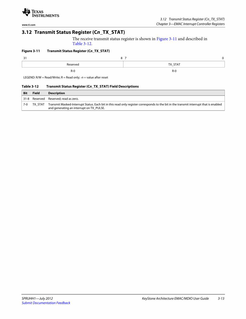
3.12 Transmit Status Register (Cn_TX_STAT)
SPRUHH1—July 2012 KeyStone Architecture EMAC/MDIO User Guide 3-13Submit Documentation Feedback
Chapter 3—EMAC Interrupt Controller Registerswww.ti.com
3.12 Transmit Status Register (Cn_TX_STAT)The receive transmit status register is shown in Figure 3-11 and described in Table 3-12.
Figure 3-11 Transmit Status Register (Cn_TX_STAT)
31 8 7 0
Reserved TX_STAT
R-0 R-0
LEGEND: R/W = Read/Write; R = Read only; -n = value after reset
Table 3-12 Transmit Status Register (Cn_TX_STAT) Field Descriptions
Bit Field Description
31-8 Reserved Reserved; read as zero.
7-0 TX_STAT Transmit Masked-Interrupt Status. Each bit in this read only register corresponds to the bit in the transmit interrupt that is enabled and generating an interrupt on TX_PULSE.
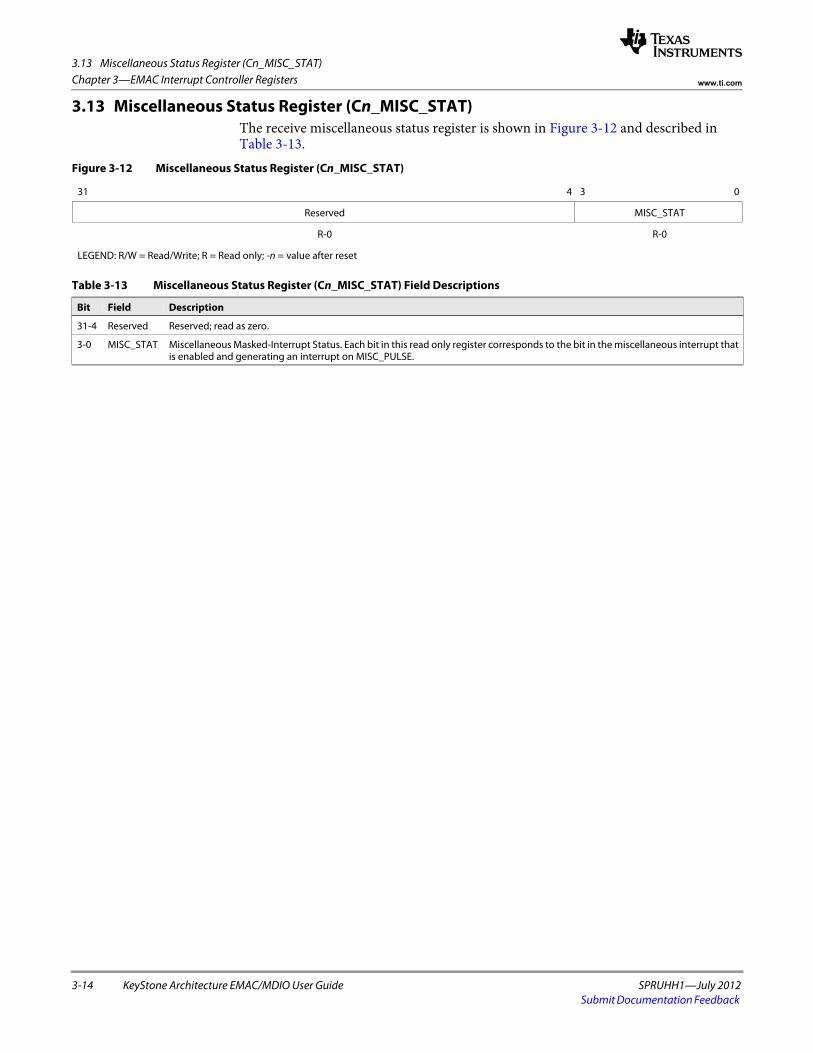
3.13 Miscellaneous Status Register (Cn_MISC_STAT)
3-14 KeyStone Architecture EMAC/MDIO User Guide SPRUHH1—July 2012Submit Documentation Feedback
Chapter 3—EMAC Interrupt Controller Registers www.ti.com
3.13 Miscellaneous Status Register (Cn_MISC_STAT)The receive miscellaneous status register is shown in Figure 3-12 and described in Table 3-13.
Figure 3-12 Miscellaneous Status Register (Cn_MISC_STAT)
31 4 3 0
Reserved MISC_STAT
R-0 R-0
LEGEND: R/W = Read/Write; R = Read only; -n = value after reset
Table 3-13 Miscellaneous Status Register (Cn_MISC_STAT) Field Descriptions
Bit Field Description
31-4 Reserved Reserved; read as zero.
3-0 MISC_STAT Miscellaneous Masked-Interrupt Status. Each bit in this read only register corresponds to the bit in the miscellaneous interrupt that is enabled and generating an interrupt on MISC_PULSE.
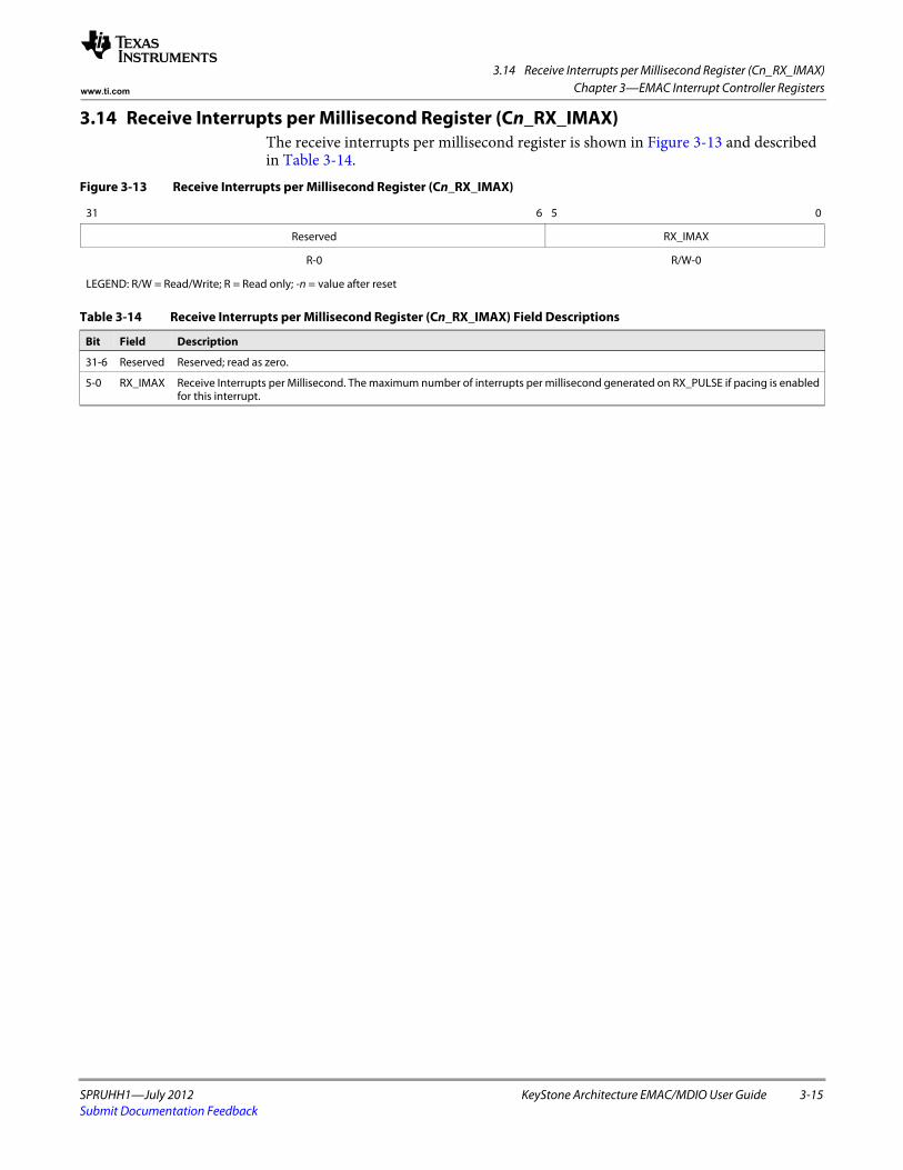
3.14 Receive Interrupts per Millisecond Register (Cn_RX_IMAX)
SPRUHH1—July 2012 KeyStone Architecture EMAC/MDIO User Guide 3-15Submit Documentation Feedback
Chapter 3—EMAC Interrupt Controller Registerswww.ti.com
3.14 Receive Interrupts per Millisecond Register (Cn_RX_IMAX)The receive interrupts per millisecond register is shown in Figure 3-13 and described in Table 3-14.
Figure 3-13 Receive Interrupts per Millisecond Register (Cn_RX_IMAX)
31 6 5 0
Reserved RX_IMAX
R-0 R/W-0
LEGEND: R/W = Read/Write; R = Read only; -n = value after reset
Table 3-14 Receive Interrupts per Millisecond Register (Cn_RX_IMAX) Field Descriptions
Bit Field Description
31-6 Reserved Reserved; read as zero.
5-0 RX_IMAX Receive Interrupts per Millisecond. The maximum number of interrupts per millisecond generated on RX_PULSE if pacing is enabled for this interrupt.
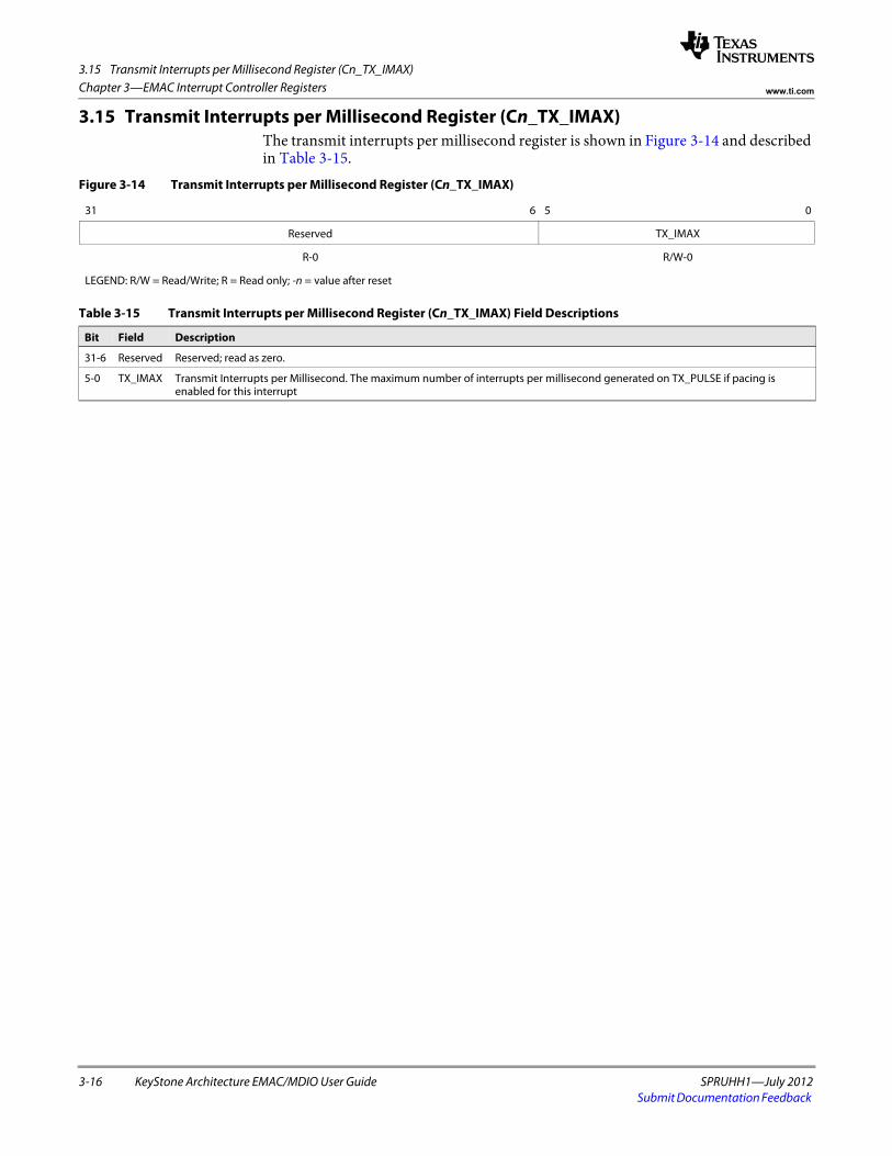
3.15 Transmit Interrupts per Millisecond Register (Cn_TX_IMAX)
3-16 KeyStone Architecture EMAC/MDIO User Guide SPRUHH1—July 2012Submit Documentation Feedback
Chapter 3—EMAC Interrupt Controller Registers www.ti.com
3.15 Transmit Interrupts per Millisecond Register (Cn_TX_IMAX)The transmit interrupts per millisecond register is shown in Figure 3-14 and described in Table 3-15.
Figure 3-14 Transmit Interrupts per Millisecond Register (Cn_TX_IMAX)
31 6 5 0
Reserved TX_IMAX
R-0 R/W-0
LEGEND: R/W = Read/Write; R = Read only; -n = value after reset
Table 3-15 Transmit Interrupts per Millisecond Register (Cn_TX_IMAX) Field Descriptions
Bit Field Description
31-6 Reserved Reserved; read as zero.
5-0 TX_IMAX Transmit Interrupts per Millisecond. The maximum number of interrupts per millisecond generated on TX_PULSE if pacing is enabled for this interrupt
SPRUHH1—July 2012 KeyStone Architecture EMAC/MDIO User Guide 4-1Submit Documentation Feedback
Chapter 4
EMAC Port Registers
4.1 "Introduction" on page 4-3 4.2 "Transmit Identification and Version Register (TXIDVER)" on page 4-6 4.3 "Transmit Control Register (TXCONTROL)" on page 4-7 4.4 "Transmit Teardown Register (TXTEARDOWN)" on page 4-8 4.5 "Receive Identification and Version Register (RXIDVER)" on page 4-9 4.6 "Receive Control Register (RXCONTROL)" on page 4-10 4.7 "Receive Teardown Register (RXTEARDOWN)" on page 4-11 4.8 "Transmit Interrupt Status (Unmasked) Register (TXINTSTATRAW)" on page 4-12 4.9 "Transmit Interrupt Status (Masked) Register (TXINTSTATMASKED)" on page 4-13
4.10 "Transmit Interrupt Mask Set Register (TXINTMASKSET)" on page 4-14 4.11 "Transmit Interrupt Mask Clear Register (TXINTMASKCLEAR)" on page 4-15 4.12 "MAC Input Vector Register (MACINVECTOR)" on page 4-16 4.13 "MAC End-of-Interrupt Vector Register (MACEOIVECTOR)" on page 4-17 4.14 "Receive Interrupt Status (Unmasked) Register (RXINTSTATRAW)" on page 4-18 4.15 "Receive Interrupt Status (Masked) Register (RXINTSTATMASKED)" on page 4-19 4.16 "Receive Interrupt Mask Set Register (RXINTMASKSET)" on page 4-20 4.17 "Receive Interrupt Mask Clear Register (RXINTMASKCLEAR)" on page 4-21 4.18 "MAC Interrupt Status (Unmasked) Register (MACINTSTATRAW)" on page 4-22 4.19 "MAC Interrupt Status (Masked) Register (MACINTSTATMASKED)" on page 4-23 4.20 "MAC Interrupt Mask Set Register (MACINTMASKSET)" on page 4-24 4.21 "MAC Interrupt Mask Clear Register (MACINTMASKCLEAR)" on page 4-25 4.22 "Receive Multicast/Broadcast/Promiscuous Channel Enable Register
(RXMBPENABLE)" on page 4-26 4.23 "Receive Unicast Enable Set Register (RXUNICASTSET)" on page 4-28 4.24 "Receive Unicast Clear Register (RXUNICASTCLEAR)" on page 4-29 4.25 "Receive Maximum Length Register (RXMAXLEN)" on page 4-30 4.26 "Receive Buffer Offset Register (RXBUFFEROFFSET)" on page 4-31 4.27 "Receive Filter Low Priority Frame Threshold Register (RXFILTERLOWTHRESH)" on
page 4-32 4.28 "Receive Channel 0-7 Flow Control Threshold Register (RXnFLOWTHRESH)" on
page 4-33
4-2 KeyStone Architecture EMAC/MDIO User Guide SPRUHH1—July 2012Submit Documentation Feedback
Chapter 4—EMAC Port Registers www.ti.com
4.29 "Receive Channel 0-7 Free Buffer Count Register (RXnFREEBUFFER)" on page 4-34 4.30 "MAC Control Register (MACCONTROL)" on page 4-35 4.31 "MAC Status Register (MACSTATUS)" on page 4-37 4.32 "Emulation Control Register (EMCONTROL)" on page 4-39 4.33 "FIFO Control Register (FIFOCONTROL)" on page 4-40 4.34 "MAC Configuration Register (MACCONFIG)" on page 4-41 4.35 "Soft Reset Register (SOFTRESET)" on page 4-42 4.36 "MAC Source Address Low Bytes Register (MACSRCADDRLO)" on page 4-43 4.37 "MAC Source Address High Bytes Register (MACSRCADDRHI)" on page 4-44 4.38 "MAC Hash Address Register 1 (MACHASH1)" on page 4-45 4.39 "MAC Hash Address Register 2 (MACHASH2)" on page 4-46 4.40 "Back Off Test Register (BOFFTEST)" on page 4-47 4.41 "Transmit Pacing Algorithm Test Register (TPACETEST)" on page 4-48 4.42 "Receive Pause Timer Register (RXPAUSE)" on page 4-49 4.43 "Transmit Pause Timer Register (TXPAUSE)" on page 4-50 4.44 "MAC Address Low Bytes Register (MACADDRLO)" on page 4-51 4.45 "MAC Address High Bytes Register (MACADDRHI)" on page 4-52 4.46 "MAC Index Register (MACINDEX)" on page 4-53 4.47 "Transmit Channel 0-7 DMA Head Descriptor Pointer Register (TXnHDP)" on
page 4-54 4.48 "Receive Channel 0-7 DMA Head Descriptor Pointer Register (RXnHDP)" on
page 4-55 4.49 "Transmit Channel 0-7 Completion Pointer Register (TXnCP)" on page 4-56 4.50 "Receive Channel 0-7 Completion Pointer Register (RXnCP)" on page 4-57
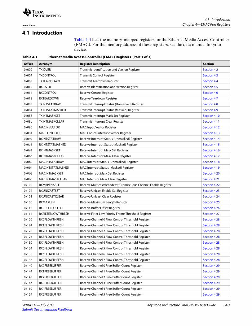
4.1 Introduction
SPRUHH1—July 2012 KeyStone Architecture EMAC/MDIO User Guide 4-3Submit Documentation Feedback
Chapter 4—EMAC Port Registerswww.ti.com
4.1 IntroductionTable 4-1 lists the memory-mapped registers for the Ethernet Media Access Controller (EMAC). For the memory address of these registers, see the data manual for your device.
Table 4-1 Ethernet Media Access Controller (EMAC) Registers (Part 1 of 3)
Offset Acronym Register Description Section
0x000 TXIDVER Transmit Identification and Version Register Section 4.2
0x004 TXCONTROL Transmit Control Register Section 4.3
0x008 TXTEAR DOWN Transmit Teardown Register Section 4.4
0x010 RXIDVER Receive Identification and Version Register Section 4.5
0x014 RXCONTROL Receive Control Register Section 4.6
0x018 RXTEARDOWN Receive Teardown Register Section 4.7
0x080 TXINTSTATRAW Transmit Interrupt Status (Unmasked) Register Section 4.8
0x084 TXINTSTATMASKED Transmit Interrupt Status (Masked) Register Section 4.9
0x088 TXINTMASKSET Transmit Interrupt Mask Set Register Section 4.10
0x08c TXINTMASKCLEAR Transmit Interrupt Clear Register Section 4.11
0x090 MACINVECTOR MAC Input Vector Register Section 4.12
0x094 MACEOIVECTOR MAC End-of-Interrupt Vector Register Section 4.13
0x0a0 RXINTSTATRAW Receive Interrupt Status (Unmasked) Register Section 4.14
0x0a4 RXINTSTATMASKED Receive Interrupt Status (Masked) Register Section 4.15
0x0a8 RXINTMASKSET Receive Interrupt Mask Set Register Section 4.16
0x0ac RXINTMASKCLEAR Receive Interrupt Mask Clear Register Section 4.17
0x0b0 MACINTSTATRAW MAC Interrupt Status (Unmasked) Register Section 4.18
0x0b4 MACINTSTATMASKED MAC Interrupt Status (Masked) Register Section 4.19
0x0b8 MACINTMASKSET MAC Interrupt Mask Set Register Section 4.20
0x0bc MACINTMASKCLEAR MAC Interrupt Mask Clear Register Section 4.21
0x100 RXMBPENABLE Receive Multicast/Broadcast/Promiscuous Channel Enable Register Section 4.22
0x104 RXUNICASTSET Receive Unicast Enable Set Register Section 4.23
0x108 RXUNICASTCLEAR Receive Unicast Clear Register Section 4.24
0x10c RXMAXLEN Receive Maximum Length Register Section 4.25
0x110 RXBUFFEROFFSET Receive Buffer Offset Register Section 4.26
0x114 RXFILTERLOWTHRESH Receive Filter Low Priority Frame Threshold Register Section 4.27
0x120 RX0FLOWTHRESH Receive Channel 0 Flow Control Threshold Register Section 4.28
0x124 RX1FLOWTHRESH Receive Channel 1 Flow Control Threshold Register Section 4.28
0x128 RX2FLOWTHRESH Receive Channel 2 Flow Control Threshold Register Section 4.28
0x12c RX3FLOWTHRESH Receive Channel 3 Flow Control Threshold Register Section 4.28
0x130 RX4FLOWTHRESH Receive Channel 4 Flow Control Threshold Register Section 4.28
0x134 RX5FLOWTHRESH Receive Channel 5 Flow Control Threshold Register Section 4.28
0x138 RX6FLOWTHRESH Receive Channel 6 Flow Control Threshold Register Section 4.28
0x13c RX7FLOWTHRESH Receive Channel 7 Flow Control Threshold Register Section 4.28
0x140 RX0FREEBUFFER Receive Channel 0 Free Buffer Count Register Section 4.29
0x144 RX1FREEBUFFER Receive Channel 1 Free Buffer Count Register Section 4.29
0x148 RX2FREEBUFFER Receive Channel 2 Free Buffer Count Register Section 4.29
0x14c RX3FREEBUFFER Receive Channel 3 Free Buffer Count Register Section 4.29
0x150 RX4FREEBUFFER Receive Channel 4 Free Buffer Count Register Section 4.29
0x154 RX5FREEBUFFER Receive Channel 5 Free Buffer Count Register Section 4.29
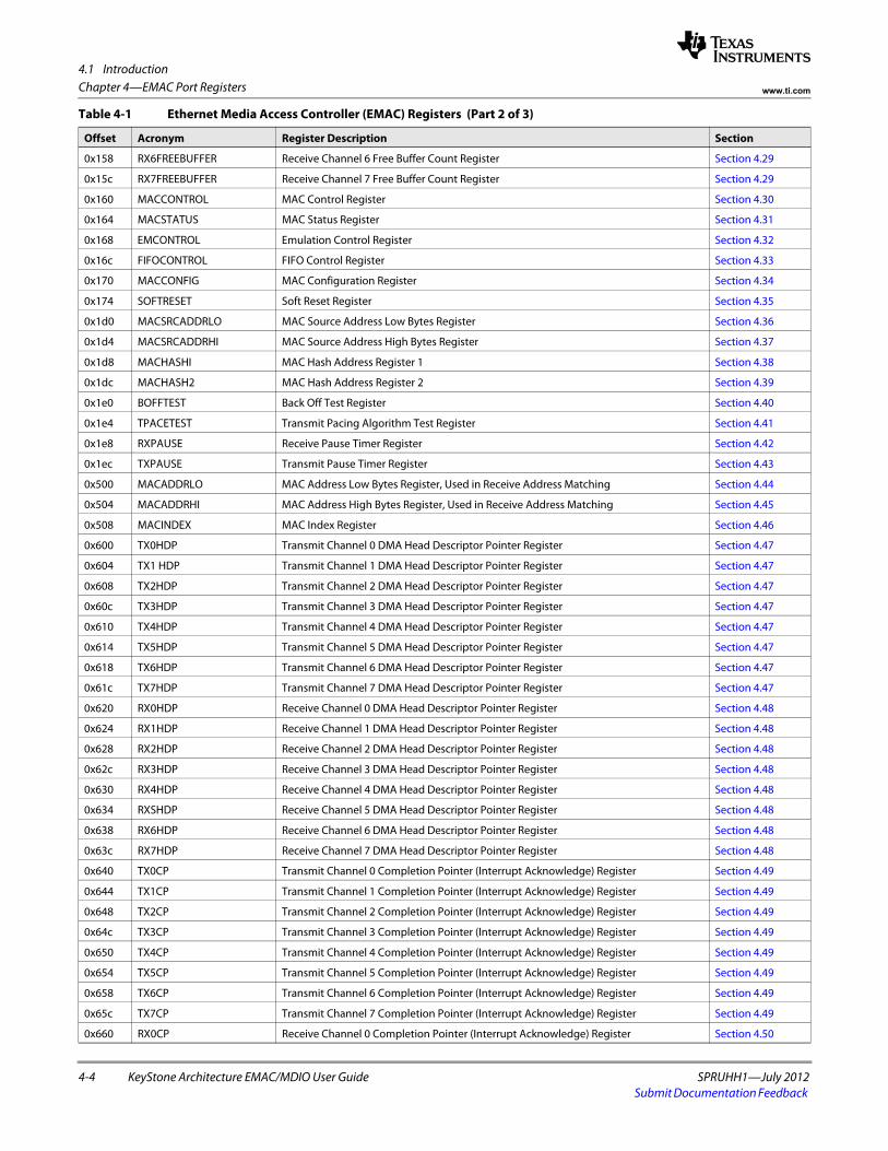
4.1 Introduction
4-4 KeyStone Architecture EMAC/MDIO User Guide SPRUHH1—July 2012Submit Documentation Feedback
Chapter 4—EMAC Port Registers www.ti.com
0x158 RX6FREEBUFFER Receive Channel 6 Free Buffer Count Register Section 4.29
0x15c RX7FREEBUFFER Receive Channel 7 Free Buffer Count Register Section 4.29
0x160 MACCONTROL MAC Control Register Section 4.30
0x164 MACSTATUS MAC Status Register Section 4.31
0x168 EMCONTROL Emulation Control Register Section 4.32
0x16c FIFOCONTROL FIFO Control Register Section 4.33
0x170 MACCONFIG MAC Configuration Register Section 4.34
0x174 SOFTRESET Soft Reset Register Section 4.35
0x1d0 MACSRCADDRLO MAC Source Address Low Bytes Register Section 4.36
0x1d4 MACSRCADDRHI MAC Source Address High Bytes Register Section 4.37
0x1d8 MACHASHI MAC Hash Address Register 1 Section 4.38
0x1dc MACHASH2 MAC Hash Address Register 2 Section 4.39
0x1e0 BOFFTEST Back Off Test Register Section 4.40
0x1e4 TPACETEST Transmit Pacing Algorithm Test Register Section 4.41
0x1e8 RXPAUSE Receive Pause Timer Register Section 4.42
0x1ec TXPAUSE Transmit Pause Timer Register Section 4.43
0x500 MACADDRLO MAC Address Low Bytes Register, Used in Receive Address Matching Section 4.44
0x504 MACADDRHI MAC Address High Bytes Register, Used in Receive Address Matching Section 4.45
0x508 MACINDEX MAC Index Register Section 4.46
0x600 TX0HDP Transmit Channel 0 DMA Head Descriptor Pointer Register Section 4.47
0x604 TX1 HDP Transmit Channel 1 DMA Head Descriptor Pointer Register Section 4.47
0x608 TX2HDP Transmit Channel 2 DMA Head Descriptor Pointer Register Section 4.47
0x60c TX3HDP Transmit Channel 3 DMA Head Descriptor Pointer Register Section 4.47
0x610 TX4HDP Transmit Channel 4 DMA Head Descriptor Pointer Register Section 4.47
0x614 TX5HDP Transmit Channel 5 DMA Head Descriptor Pointer Register Section 4.47
0x618 TX6HDP Transmit Channel 6 DMA Head Descriptor Pointer Register Section 4.47
0x61c TX7HDP Transmit Channel 7 DMA Head Descriptor Pointer Register Section 4.47
0x620 RX0HDP Receive Channel 0 DMA Head Descriptor Pointer Register Section 4.48
0x624 RX1HDP Receive Channel 1 DMA Head Descriptor Pointer Register Section 4.48
0x628 RX2HDP Receive Channel 2 DMA Head Descriptor Pointer Register Section 4.48
0x62c RX3HDP Receive Channel 3 DMA Head Descriptor Pointer Register Section 4.48
0x630 RX4HDP Receive Channel 4 DMA Head Descriptor Pointer Register Section 4.48
0x634 RXSHDP Receive Channel 5 DMA Head Descriptor Pointer Register Section 4.48
0x638 RX6HDP Receive Channel 6 DMA Head Descriptor Pointer Register Section 4.48
0x63c RX7HDP Receive Channel 7 DMA Head Descriptor Pointer Register Section 4.48
0x640 TX0CP Transmit Channel 0 Completion Pointer (Interrupt Acknowledge) Register Section 4.49
0x644 TX1CP Transmit Channel 1 Completion Pointer (Interrupt Acknowledge) Register Section 4.49
0x648 TX2CP Transmit Channel 2 Completion Pointer (Interrupt Acknowledge) Register Section 4.49
0x64c TX3CP Transmit Channel 3 Completion Pointer (Interrupt Acknowledge) Register Section 4.49
0x650 TX4CP Transmit Channel 4 Completion Pointer (Interrupt Acknowledge) Register Section 4.49
0x654 TX5CP Transmit Channel 5 Completion Pointer (Interrupt Acknowledge) Register Section 4.49
0x658 TX6CP Transmit Channel 6 Completion Pointer (Interrupt Acknowledge) Register Section 4.49
0x65c TX7CP Transmit Channel 7 Completion Pointer (Interrupt Acknowledge) Register Section 4.49
0x660 RX0CP Receive Channel 0 Completion Pointer (Interrupt Acknowledge) Register Section 4.50
Table 4-1 Ethernet Media Access Controller (EMAC) Registers (Part 2 of 3)
Offset Acronym Register Description Section
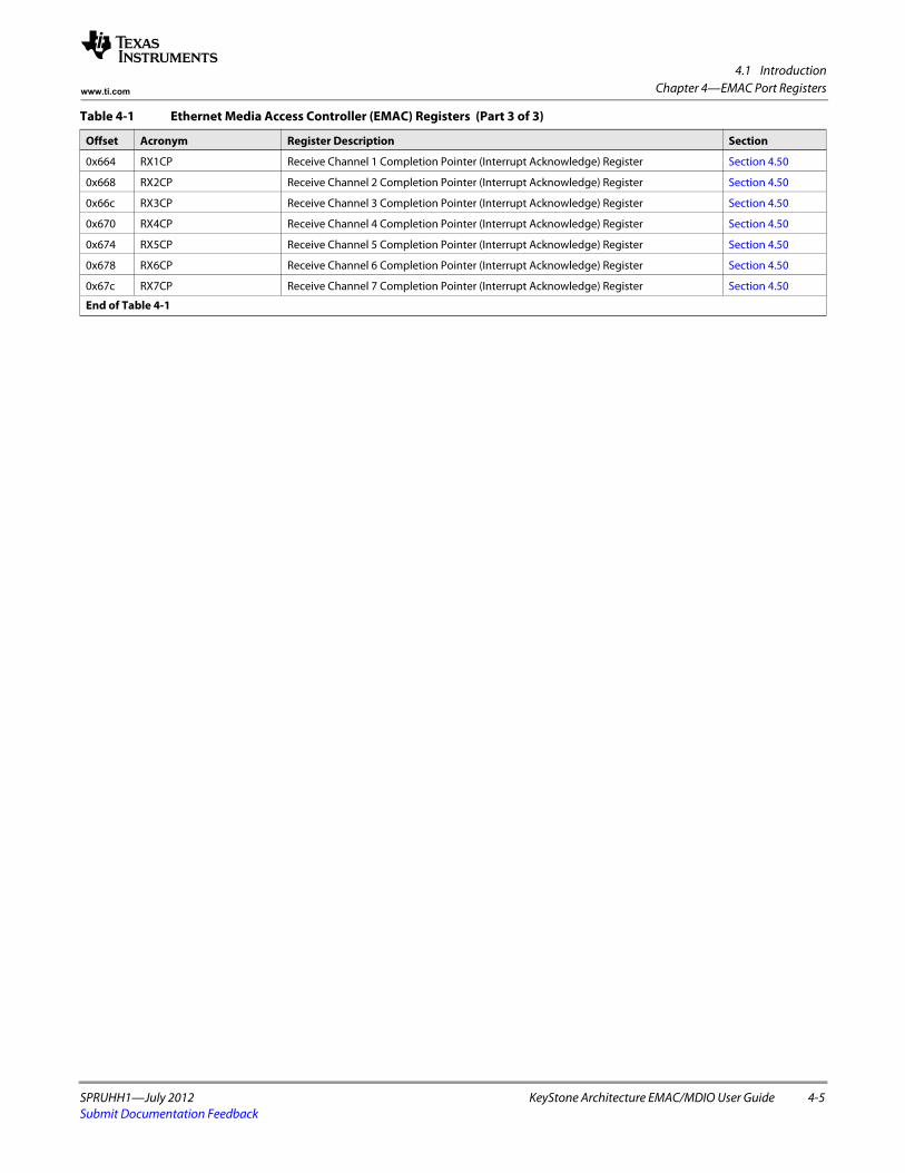
4.1 Introduction
SPRUHH1—July 2012 KeyStone Architecture EMAC/MDIO User Guide 4-5Submit Documentation Feedback
Chapter 4—EMAC Port Registerswww.ti.com
0x664 RX1CP Receive Channel 1 Completion Pointer (Interrupt Acknowledge) Register Section 4.50
0x668 RX2CP Receive Channel 2 Completion Pointer (Interrupt Acknowledge) Register Section 4.50
0x66c RX3CP Receive Channel 3 Completion Pointer (Interrupt Acknowledge) Register Section 4.50
0x670 RX4CP Receive Channel 4 Completion Pointer (Interrupt Acknowledge) Register Section 4.50
0x674 RX5CP Receive Channel 5 Completion Pointer (Interrupt Acknowledge) Register Section 4.50
0x678 RX6CP Receive Channel 6 Completion Pointer (Interrupt Acknowledge) Register Section 4.50
0x67c RX7CP Receive Channel 7 Completion Pointer (Interrupt Acknowledge) Register Section 4.50
End of Table 4-1
Table 4-1 Ethernet Media Access Controller (EMAC) Registers (Part 3 of 3)
Offset Acronym Register Description Section
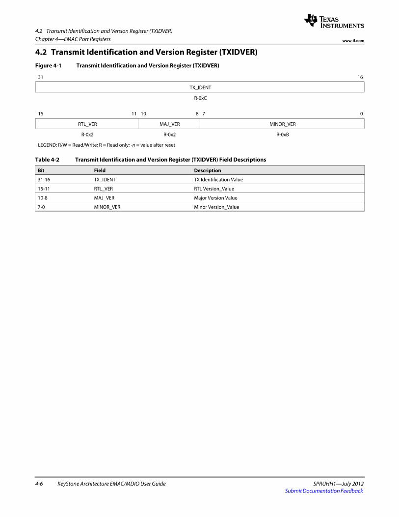
4.2 Transmit Identification and Version Register (TXIDVER)
4-6 KeyStone Architecture EMAC/MDIO User Guide SPRUHH1—July 2012Submit Documentation Feedback
Chapter 4—EMAC Port Registers www.ti.com
4.2 Transmit Identification and Version Register (TXIDVER)Figure 4-1 Transmit Identification and Version Register (TXIDVER)
31 16
TX_IDENT
R-0xCspacer
15 11 10 8 7 0
RTL_VER MAJ_VER MINOR_VER
R-0x2 R-0x2 R-0xB
LEGEND: R/W = Read/Write; R = Read only; -n = value after reset
Table 4-2 Transmit Identification and Version Register (TXIDVER) Field Descriptions
Bit Field Description
31-16 TX_IDENT TX Identification Value
15-11 RTL_VER RTL Version_Value
10-8 MAJ_VER Major Version Value
7-0 MINOR_VER Minor Version_Value
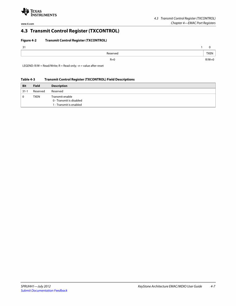
4.3 Transmit Control Register (TXCONTROL)
SPRUHH1—July 2012 KeyStone Architecture EMAC/MDIO User Guide 4-7Submit Documentation Feedback
Chapter 4—EMAC Port Registerswww.ti.com
4.3 Transmit Control Register (TXCONTROL)
Figure 4-2 Transmit Control Register (TXCONTROL)
31 1 0
Reserved TXEN
R=0 R/W=0
LEGEND: R/W = Read/Write; R = Read only; -n = value after reset
Table 4-3 Transmit Control Register (TXCONTROL) Field Descriptions
Bit Field Description
31-1 Reserved Reserved
0 TXEN Transmit enable 0 - Transmit is disabled 1 - Transmit is enabled
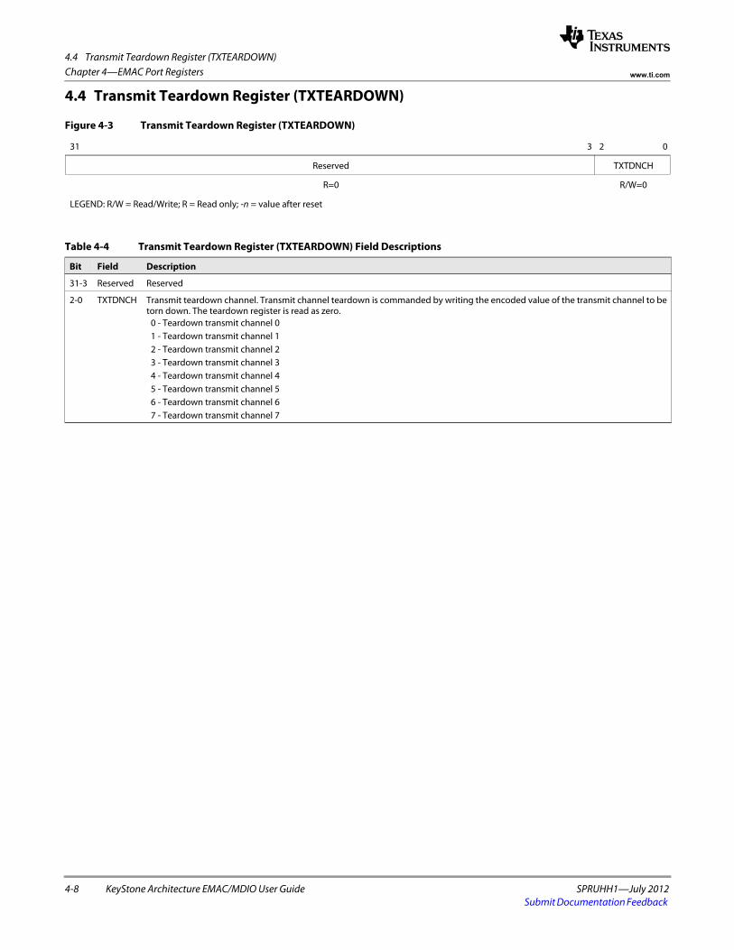
4.4 Transmit Teardown Register (TXTEARDOWN)
4-8 KeyStone Architecture EMAC/MDIO User Guide SPRUHH1—July 2012Submit Documentation Feedback
Chapter 4—EMAC Port Registers www.ti.com
4.4 Transmit Teardown Register (TXTEARDOWN)
Figure 4-3 Transmit Teardown Register (TXTEARDOWN)
31 3 2 0
Reserved TXTDNCH
R=0 R/W=0
LEGEND: R/W = Read/Write; R = Read only; -n = value after reset
Table 4-4 Transmit Teardown Register (TXTEARDOWN) Field Descriptions
Bit Field Description
31-3 Reserved Reserved
2-0 TXTDNCH Transmit teardown channel. Transmit channel teardown is commanded by writing the encoded value of the transmit channel to be torn down. The teardown register is read as zero.
0 - Teardown transmit channel 0 1 - Teardown transmit channel 1 2 - Teardown transmit channel 2 3 - Teardown transmit channel 3 4 - Teardown transmit channel 4 5 - Teardown transmit channel 5 6 - Teardown transmit channel 6 7 - Teardown transmit channel 7
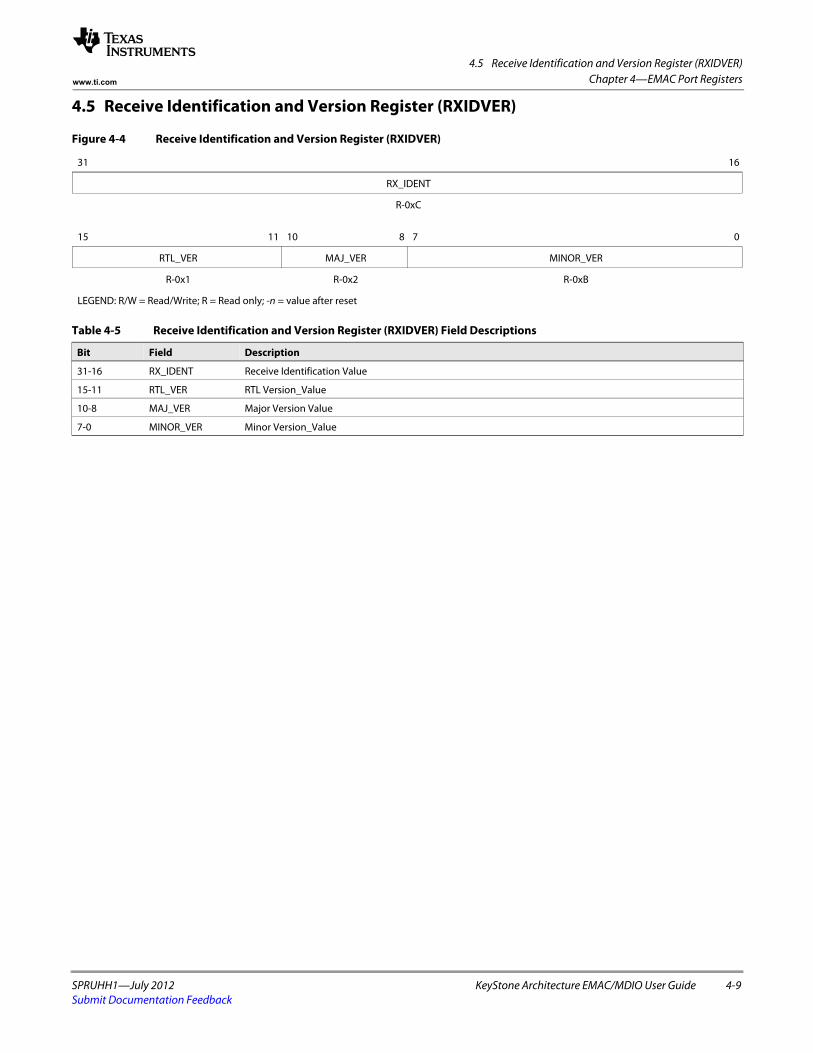
4.5 Receive Identification and Version Register (RXIDVER)
SPRUHH1—July 2012 KeyStone Architecture EMAC/MDIO User Guide 4-9Submit Documentation Feedback
Chapter 4—EMAC Port Registerswww.ti.com
4.5 Receive Identification and Version Register (RXIDVER)
Figure 4-4 Receive Identification and Version Register (RXIDVER)
31 16
RX_IDENT
R-0xC spacer
15 11 10 8 7 0
RTL_VER MAJ_VER MINOR_VER
R-0x1 R-0x2 R-0xB
LEGEND: R/W = Read/Write; R = Read only; -n = value after reset
Table 4-5 Receive Identification and Version Register (RXIDVER) Field Descriptions
Bit Field Description
31-16 RX_IDENT Receive Identification Value
15-11 RTL_VER RTL Version_Value
10-8 MAJ_VER Major Version Value
7-0 MINOR_VER Minor Version_Value
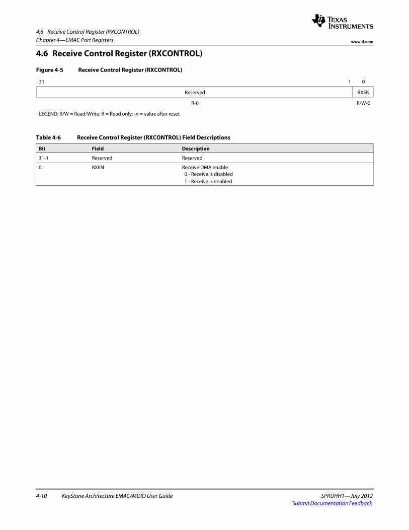
4.6 Receive Control Register (RXCONTROL)
4-10 KeyStone Architecture EMAC/MDIO User Guide SPRUHH1—July 2012Submit Documentation Feedback
Chapter 4—EMAC Port Registers www.ti.com
4.6 Receive Control Register (RXCONTROL)
Figure 4-5 Receive Control Register (RXCONTROL)
31 1 0
Reserved RXEN
R-0 R/W-0
LEGEND: R/W = Read/Write; R = Read only; -n = value after reset
Table 4-6 Receive Control Register (RXCONTROL) Field Descriptions
Bit Field Description
31-1 Reserved Reserved
0 RXEN Receive DMA enable 0 - Receive is disabled 1 - Receive is enabled
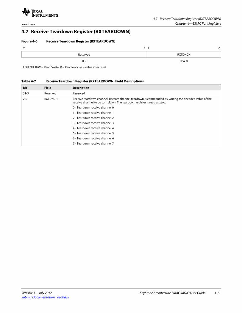
4.7 Receive Teardown Register (RXTEARDOWN)
SPRUHH1—July 2012 KeyStone Architecture EMAC/MDIO User Guide 4-11Submit Documentation Feedback
Chapter 4—EMAC Port Registerswww.ti.com
4.7 Receive Teardown Register (RXTEARDOWN)
Figure 4-6 Receive Teardown Register (RXTEARDOWN)
7 3 2 0
Reserved RXTDNCH
R-0 R/W-0
LEGEND: R/W = Read/Write; R = Read only; -n = value after reset
Table 4-7 Receive Teardown Register (RXTEARDOWN) Field Descriptions
Bit Field Description
31-3 Reserved Reserved
2-0 RXTDNCH Receive teardown channel. Receive channel teardown is commanded by writing the encoded value of the receive channel to be torn down. The teardown register is read as zero.
0 - Teardown receive channel 0
1 - Teardown receive channel 1
2 - Teardown receive channel 2
3 - Teardown receive channel 3
4 - Teardown receive channel 4
5 - Teardown receive channel 5
6 - Teardown receive channel 6
7 - Teardown receive channel 7
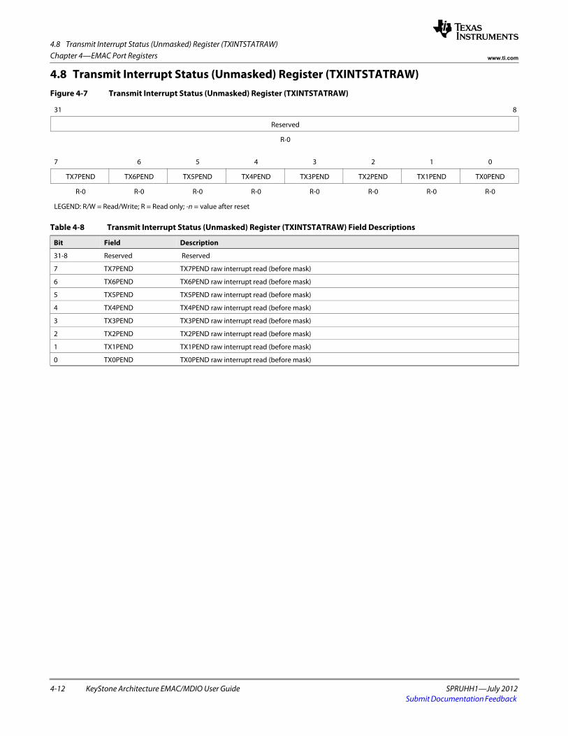
4.8 Transmit Interrupt Status (Unmasked) Register (TXINTSTATRAW)
4-12 KeyStone Architecture EMAC/MDIO User Guide SPRUHH1—July 2012Submit Documentation Feedback
Chapter 4—EMAC Port Registers www.ti.com
4.8 Transmit Interrupt Status (Unmasked) Register (TXINTSTATRAW)Figure 4-7 Transmit Interrupt Status (Unmasked) Register (TXINTSTATRAW)
31 8
Reserved
R-0spacer
7 6 5 4 3 2 1 0
TX7PEND TX6PEND TX5PEND TX4PEND TX3PEND TX2PEND TX1PEND TX0PEND
R-0 R-0 R-0 R-0 R-0 R-0 R-0 R-0
LEGEND: R/W = Read/Write; R = Read only; -n = value after reset
Table 4-8 Transmit Interrupt Status (Unmasked) Register (TXINTSTATRAW) Field Descriptions
Bit Field Description
31-8 Reserved Reserved
7 TX7PEND TX7PEND raw interrupt read (before mask)
6 TX6PEND TX6PEND raw interrupt read (before mask)
5 TX5PEND TX5PEND raw interrupt read (before mask)
4 TX4PEND TX4PEND raw interrupt read (before mask)
3 TX3PEND TX3PEND raw interrupt read (before mask)
2 TX2PEND TX2PEND raw interrupt read (before mask)
1 TX1PEND TX1PEND raw interrupt read (before mask)
0 TX0PEND TX0PEND raw interrupt read (before mask)
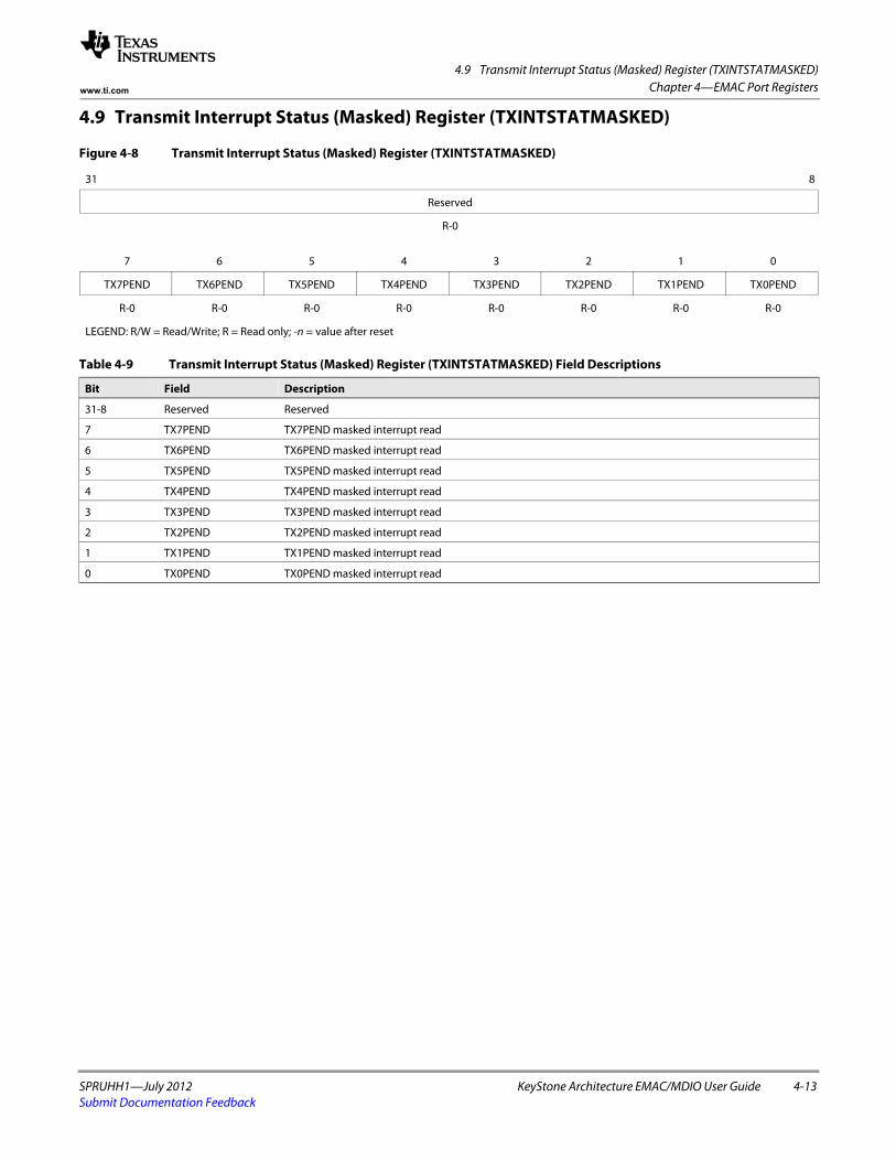
4.9 Transmit Interrupt Status (Masked) Register (TXINTSTATMASKED)
SPRUHH1—July 2012 KeyStone Architecture EMAC/MDIO User Guide 4-13Submit Documentation Feedback
Chapter 4—EMAC Port Registerswww.ti.com
4.9 Transmit Interrupt Status (Masked) Register (TXINTSTATMASKED)
Figure 4-8 Transmit Interrupt Status (Masked) Register (TXINTSTATMASKED)
31 8
Reserved
R-0spacer
7 6 5 4 3 2 1 0
TX7PEND TX6PEND TX5PEND TX4PEND TX3PEND TX2PEND TX1PEND TX0PEND
R-0 R-0 R-0 R-0 R-0 R-0 R-0 R-0
LEGEND: R/W = Read/Write; R = Read only; -n = value after reset
Table 4-9 Transmit Interrupt Status (Masked) Register (TXINTSTATMASKED) Field Descriptions
Bit Field Description
31-8 Reserved Reserved
7 TX7PEND TX7PEND masked interrupt read
6 TX6PEND TX6PEND masked interrupt read
5 TX5PEND TX5PEND masked interrupt read
4 TX4PEND TX4PEND masked interrupt read
3 TX3PEND TX3PEND masked interrupt read
2 TX2PEND TX2PEND masked interrupt read
1 TX1PEND TX1PEND masked interrupt read
0 TX0PEND TX0PEND masked interrupt read
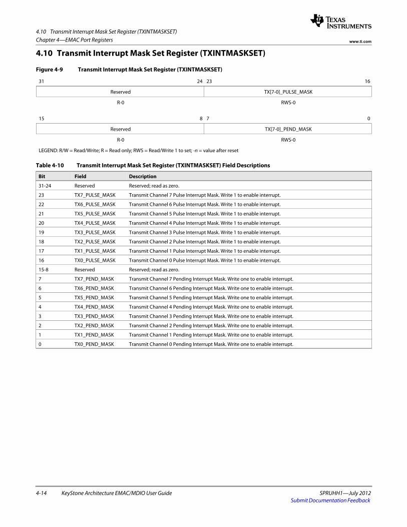
4.10 Transmit Interrupt Mask Set Register (TXINTMASKSET)
4-14 KeyStone Architecture EMAC/MDIO User Guide SPRUHH1—July 2012Submit Documentation Feedback
Chapter 4—EMAC Port Registers www.ti.com
4.10 Transmit Interrupt Mask Set Register (TXINTMASKSET)
Figure 4-9 Transmit Interrupt Mask Set Register (TXINTMASKSET)
31 24 23 16
Reserved TX[7-0]_PULSE_MASK
R-0 RWS-0spacer
15 8 7 0
Reserved TX[7-0]_PEND_MASK
R-0 RWS-0
LEGEND: R/W = Read/Write; R = Read only; RWS = Read/Write 1 to set; -n = value after reset
Table 4-10 Transmit Interrupt Mask Set Register (TXINTMASKSET) Field Descriptions
Bit Field Description
31-24 Reserved Reserved; read as zero.
23 TX7_PULSE_MASK Transmit Channel 7 Pulse Interrupt Mask. Write 1 to enable interrupt.
22 TX6_PULSE_MASK Transmit Channel 6 Pulse Interrupt Mask. Write 1 to enable interrupt.
21 TX5_PULSE_MASK Transmit Channel 5 Pulse Interrupt Mask. Write 1 to enable interrupt.
20 TX4_PULSE_MASK Transmit Channel 4 Pulse Interrupt Mask. Write 1 to enable interrupt.
19 TX3_PULSE_MASK Transmit Channel 3 Pulse Interrupt Mask. Write 1 to enable interrupt.
18 TX2_PULSE_MASK Transmit Channel 2 Pulse Interrupt Mask. Write 1 to enable interrupt.
17 TX1_PULSE_MASK Transmit Channel 1 Pulse Interrupt Mask. Write 1 to enable interrupt.
16 TX0_PULSE_MASK Transmit Channel 0 Pulse Interrupt Mask. Write 1 to enable interrupt.
15-8 Reserved Reserved; read as zero.
7 TX7_PEND_MASK Transmit Channel 7 Pending Interrupt Mask. Write one to enable interrupt.
6 TX6_PEND_MASK Transmit Channel 6 Pending Interrupt Mask. Write one to enable interrupt.
5 TX5_PEND_MASK Transmit Channel 5 Pending Interrupt Mask. Write one to enable interrupt.
4 TX4_PEND_MASK Transmit Channel 4 Pending Interrupt Mask. Write one to enable interrupt.
3 TX3_PEND_MASK Transmit Channel 3 Pending Interrupt Mask. Write one to enable interrupt.
2 TX2_PEND_MASK Transmit Channel 2 Pending Interrupt Mask. Write one to enable interrupt.
1 TX1_PEND_MASK Transmit Channel 1 Pending Interrupt Mask. Write one to enable interrupt.
0 TX0_PEND_MASK Transmit Channel 0 Pending Interrupt Mask. Write one to enable interrupt.
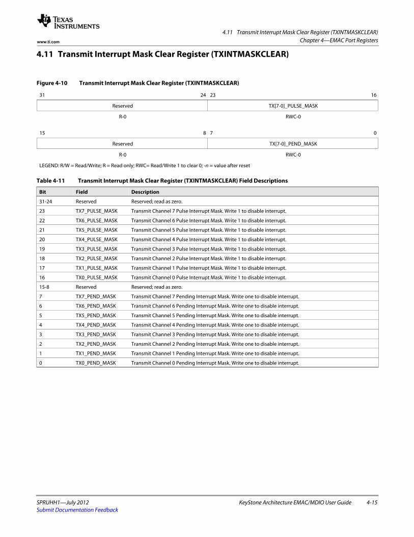
4.11 Transmit Interrupt Mask Clear Register (TXINTMASKCLEAR)
SPRUHH1—July 2012 KeyStone Architecture EMAC/MDIO User Guide 4-15Submit Documentation Feedback
Chapter 4—EMAC Port Registerswww.ti.com
4.11 Transmit Interrupt Mask Clear Register (TXINTMASKCLEAR)
Figure 4-10 Transmit Interrupt Mask Clear Register (TXINTMASKCLEAR)
31 24 23 16
Reserved TX[7-0]_PULSE_MASK
R-0 RWC-0spacer
15 8 7 0
Reserved TX[7-0]_PEND_MASK
R-0 RWC-0
LEGEND: R/W = Read/Write; R = Read only; RWC= Read/Write 1 to clear 0; -n = value after reset
Table 4-11 Transmit Interrupt Mask Clear Register (TXINTMASKCLEAR) Field Descriptions
Bit Field Description
31-24 Reserved Reserved; read as zero.
23 TX7_PULSE_MASK Transmit Channel 7 Pulse Interrupt Mask. Write 1 to disable interrupt.
22 TX6_PULSE_MASK Transmit Channel 6 Pulse Interrupt Mask. Write 1 to disable interrupt.
21 TX5_PULSE_MASK Transmit Channel 5 Pulse Interrupt Mask. Write 1 to disable interrupt.
20 TX4_PULSE_MASK Transmit Channel 4 Pulse Interrupt Mask. Write 1 to disable interrupt.
19 TX3_PULSE_MASK Transmit Channel 3 Pulse Interrupt Mask. Write 1 to disable interrupt.
18 TX2_PULSE_MASK Transmit Channel 2 Pulse Interrupt Mask. Write 1 to disable interrupt.
17 TX1_PULSE_MASK Transmit Channel 1 Pulse Interrupt Mask. Write 1 to disable interrupt.
16 TX0_PULSE_MASK Transmit Channel 0 Pulse Interrupt Mask. Write 1 to disable interrupt.
15-8 Reserved Reserved; read as zero.
7 TX7_PEND_MASK Transmit Channel 7 Pending Interrupt Mask. Write one to disable interrupt.
6 TX6_PEND_MASK Transmit Channel 6 Pending Interrupt Mask. Write one to disable interrupt.
5 TX5_PEND_MASK Transmit Channel 5 Pending Interrupt Mask. Write one to disable interrupt.
4 TX4_PEND_MASK Transmit Channel 4 Pending Interrupt Mask. Write one to disable interrupt.
3 TX3_PEND_MASK Transmit Channel 3 Pending Interrupt Mask. Write one to disable interrupt.
2 TX2_PEND_MASK Transmit Channel 2 Pending Interrupt Mask. Write one to disable interrupt.
1 TX1_PEND_MASK Transmit Channel 1 Pending Interrupt Mask. Write one to disable interrupt.
0 TX0_PEND_MASK Transmit Channel 0 Pending Interrupt Mask. Write one to disable interrupt.
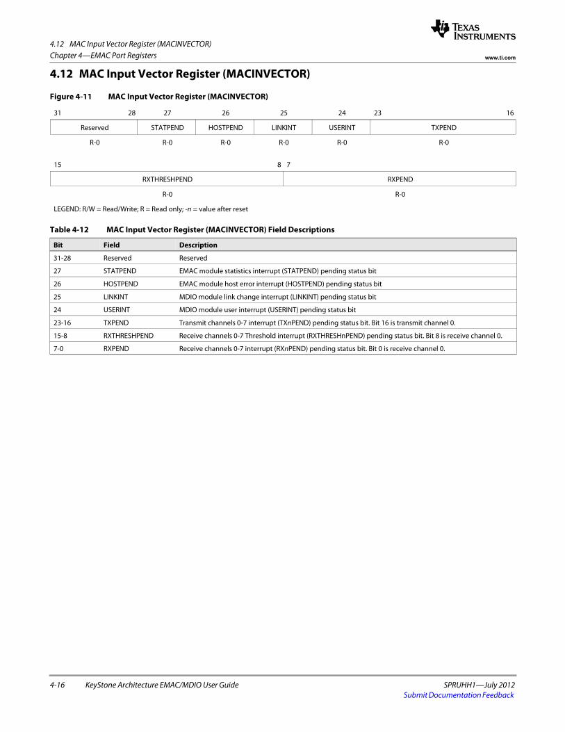
4.12 MAC Input Vector Register (MACINVECTOR)
4-16 KeyStone Architecture EMAC/MDIO User Guide SPRUHH1—July 2012Submit Documentation Feedback
Chapter 4—EMAC Port Registers www.ti.com
4.12 MAC Input Vector Register (MACINVECTOR)
Figure 4-11 MAC Input Vector Register (MACINVECTOR)
31 28 27 26 25 24 23 16
Reserved STATPEND HOSTPEND LINKINT USERINT TXPEND
R-0 R-0 R-0 R-0 R-0 R-0spacer
15 8 7
RXTHRESHPEND RXPEND
R-0 R-0
LEGEND: R/W = Read/Write; R = Read only; -n = value after reset
Table 4-12 MAC Input Vector Register (MACINVECTOR) Field Descriptions
Bit Field Description
31-28 Reserved Reserved
27 STATPEND EMAC module statistics interrupt (STATPEND) pending status bit
26 HOSTPEND EMAC module host error interrupt (HOSTPEND) pending status bit
25 LINKINT MDIO module link change interrupt (LINKINT) pending status bit
24 USERINT MDIO module user interrupt (USERINT) pending status bit
23-16 TXPEND Transmit channels 0-7 interrupt (TXnPEND) pending status bit. Bit 16 is transmit channel 0.
15-8 RXTHRESHPEND Receive channels 0-7 Threshold interrupt (RXTHRESHnPEND) pending status bit. Bit 8 is receive channel 0.
7-0 RXPEND Receive channels 0-7 interrupt (RXnPEND) pending status bit. Bit 0 is receive channel 0.
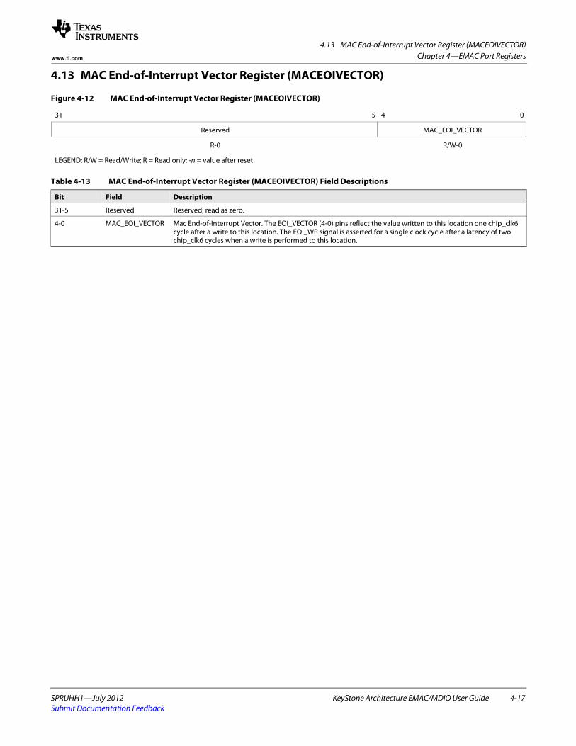
4.13 MAC End-of-Interrupt Vector Register (MACEOIVECTOR)
SPRUHH1—July 2012 KeyStone Architecture EMAC/MDIO User Guide 4-17Submit Documentation Feedback
Chapter 4—EMAC Port Registerswww.ti.com
4.13 MAC End-of-Interrupt Vector Register (MACEOIVECTOR)
Figure 4-12 MAC End-of-Interrupt Vector Register (MACEOIVECTOR)
31 5 4 0
Reserved MAC_EOI_VECTOR
R-0 R/W-0
LEGEND: R/W = Read/Write; R = Read only; -n = value after reset
Table 4-13 MAC End-of-Interrupt Vector Register (MACEOIVECTOR) Field Descriptions
Bit Field Description
31-5 Reserved Reserved; read as zero.
4-0 MAC_EOI_VECTOR Mac End-of-Interrupt Vector. The EOI_VECTOR (4-0) pins reflect the value written to this location one chip_clk6 cycle after a write to this location. The EOI_WR signal is asserted for a single clock cycle after a latency of two chip_clk6 cycles when a write is performed to this location.
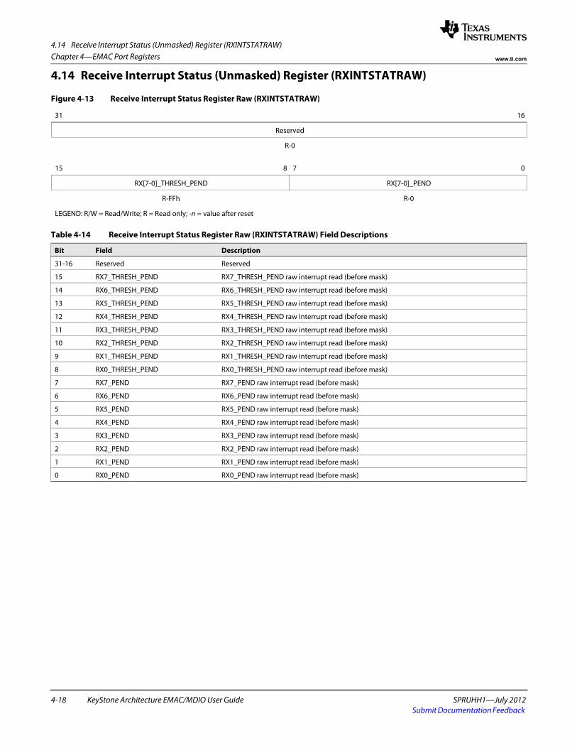
4.14 Receive Interrupt Status (Unmasked) Register (RXINTSTATRAW)
4-18 KeyStone Architecture EMAC/MDIO User Guide SPRUHH1—July 2012Submit Documentation Feedback
Chapter 4—EMAC Port Registers www.ti.com
4.14 Receive Interrupt Status (Unmasked) Register (RXINTSTATRAW)
Figure 4-13 Receive Interrupt Status Register Raw (RXINTSTATRAW)
31 16
Reserved
R-0spacer
15 8 7 0
RX[7-0]_THRESH_PEND RX[7-0]_PEND
R-FFh R-0
LEGEND: R/W = Read/Write; R = Read only; -n = value after reset
Table 4-14 Receive Interrupt Status Register Raw (RXINTSTATRAW) Field Descriptions
Bit Field Description
31-16 Reserved Reserved
15 RX7_THRESH_PEND RX7_THRESH_PEND raw interrupt read (before mask)
14 RX6_THRESH_PEND RX6_THRESH_PEND raw interrupt read (before mask)
13 RX5_THRESH_PEND RX5_THRESH_PEND raw interrupt read (before mask)
12 RX4_THRESH_PEND RX4_THRESH_PEND raw interrupt read (before mask)
11 RX3_THRESH_PEND RX3_THRESH_PEND raw interrupt read (before mask)
10 RX2_THRESH_PEND RX2_THRESH_PEND raw interrupt read (before mask)
9 RX1_THRESH_PEND RX1_THRESH_PEND raw interrupt read (before mask)
8 RX0_THRESH_PEND RX0_THRESH_PEND raw interrupt read (before mask)
7 RX7_PEND RX7_PEND raw interrupt read (before mask)
6 RX6_PEND RX6_PEND raw interrupt read (before mask)
5 RX5_PEND RX5_PEND raw interrupt read (before mask)
4 RX4_PEND RX4_PEND raw interrupt read (before mask)
3 RX3_PEND RX3_PEND raw interrupt read (before mask)
2 RX2_PEND RX2_PEND raw interrupt read (before mask)
1 RX1_PEND RX1_PEND raw interrupt read (before mask)
0 RX0_PEND RX0_PEND raw interrupt read (before mask)
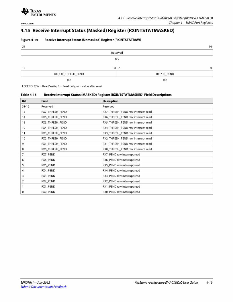
4.15 Receive Interrupt Status (Masked) Register (RXINTSTATMASKED)
SPRUHH1—July 2012 KeyStone Architecture EMAC/MDIO User Guide 4-19Submit Documentation Feedback
Chapter 4—EMAC Port Registerswww.ti.com
4.15 Receive Interrupt Status (Masked) Register (RXINTSTATMASKED)
Figure 4-14 Receive Interrupt Status (Unmasked) Register (RXINTSTATRAW)
31 16
Reserved
R-0spacer
15 8 7 0
RX[7-0]_THRESH_PEND RX[7-0]_PEND
R-0 R-0
LEGEND: R/W = Read/Write; R = Read only; -n = value after reset
Table 4-15 Receive Interrupt Status (MASKED) Register (RXINTSTATMASKED) Field Descriptions
Bit Field Description
31-16 Reserved Reserved
15 RX7_THRESH_PEND RX7_THRESH_PEND raw interrupt read
14 RX6_THRESH_PEND RX6_THRESH_PEND raw interrupt read
13 RX5_THRESH_PEND RX5_THRESH_PEND raw interrupt read
12 RX4_THRESH_PEND RX4_THRESH_PEND raw interrupt read
11 RX3_THRESH_PEND RX3_THRESH_PEND raw interrupt read
10 RX2_THRESH_PEND RX2_THRESH_PEND raw interrupt read
9 RX1_THRESH_PEND RX1_THRESH_PEND raw interrupt read
8 RX0_THRESH_PEND RX0_THRESH_PEND raw interrupt read
7 RX7_PEND RX7_PEND raw interrupt read
6 RX6_PEND RX6_PEND raw interrupt read
5 RX5_PEND RX5_PEND raw interrupt read
4 RX4_PEND RX4_PEND raw interrupt read
3 RX3_PEND RX3_PEND raw interrupt read
2 RX2_PEND RX2_PEND raw interrupt read
1 RX1_PEND RX1_PEND raw interrupt read
0 RX0_PEND RX0_PEND raw interrupt read
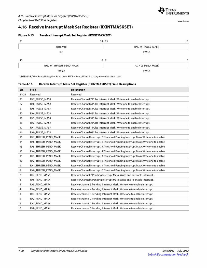
4.16 Receive Interrupt Mask Set Register (RXINTMASKSET)
4-20 KeyStone Architecture EMAC/MDIO User Guide SPRUHH1—July 2012Submit Documentation Feedback
Chapter 4—EMAC Port Registers www.ti.com
4.16 Receive Interrupt Mask Set Register (RXINTMASKSET)
Figure 4-15 Receive Interrupt Mask Set Register (RXINTMASKSET)
31 24 23 16
Reserved RX[7-0]_PULSE_MASK
R-0 RWS-0spacer
15 8 7 0
RX[7-0]_THRESH_PEND_MASK RX[7-0]_PEND_MASK
RWS-0 RWS-0
LEGEND: R/W = Read/Write; R = Read only; RWS = Read/Write 1 to set; -n = value after reset
Table 4-16 Receive Interrupt Mask Set Register (RXINTMASKSET) Field Descriptions
Bit Field Description
31-24 Reserved Reserved
23 RX7_PULSE_MASK Receive Channel 7 Pulse Interrupt Mask. Write one to enable Interrupt.
22 RX6_PULSE_MASK Receive Channel 6 Pulse Interrupt Mask. Write one to enable Interrupt.
21 RX5_PULSE_MASK Receive Channel 5 Pulse Interrupt Mask. Write one to enable Interrupt.
20 RX4_PULSE_MASK Receive Channel 4 Pulse Interrupt Mask. Write one to enable Interrupt.
19 RX3_PULSE_MASK Receive Channel 3 Pulse Interrupt Mask. Write one to enable Interrupt.
18 RX2_PULSE_MASK Receive Channel 2 Pulse Interrupt Mask. Write one to enable Interrupt.
17 RX1_PULSE_MASK Receive Channel 1 Pulse Interrupt Mask. Write one to enable Interrupt.
16 RX0_PULSE_MASK Receive Channel 0 Pulse Interrupt Mask. Write one to enable Interrupt.
15 RX7_THRESH_PEND_MASK Receive Channel Interrupt. 7 Threshold Pending Interrupt Mask.Write one to enable
14 RX6_THRESH_PEND_MASK Receive Channel Interrupt. 6 Threshold Pending Interrupt Mask.Write one to enable
13 RX5_THRESH_PEND_MASK Receive Channel Interrupt. 5 Threshold Pending Interrupt Mask.Write one to enable
12 RX4_THRESH_PEND_MASK Receive Channel Interrupt. 4 Threshold Pending Interrupt Mask.Write one to enable
11 RX3_THRESH_PEND_MASK Receive Channel Interrupt. 3 Threshold Pending Interrupt Mask.Write one to enable
10 RX2_THRESH_PEND_MASK Receive Channel Interrupt. 2 Threshold Pending Interrupt Mask.Write one to enable
9 RX1_THRESH_PEND_MASK Receive Channel Interrupt. 1 Threshold Pending Interrupt Mask.Write one to enable
8 RX0_THRESH_PEND_MASK Receive Channel Interrupt. 0 Threshold Pending Interrupt Mask.Write one to enable
7 RX7_PEND_MASK Receive Channel 7 Pending Interrupt Mask. Write one to enable Interrupt.
6 RX6_PEND_MASK Receive Channel 6 Pending Interrupt Mask. Write one to enable Interrupt.
5 RX5_PEND_MASK Receive channel 5 Pending Interrupt Mask. Write one to enable Interrupt.
4 RX4_PEND_MASK Receive channel 4 Pending Interrupt Mask. Write one to enable Interrupt.
3 RX3_PEND_MASK Receive channel 3 Pending Interrupt Mask. Write one to enable Interrupt.
2 RX2_PEND_MASK Receive channel 2 Pending Interrupt Mask. Write one to enable Interrupt.
1 RX1_PEND_MASK Receive channel 1 Pending Interrupt Mask. Write one to enable Interrupt.
0 RX0_PEND_MASK Receive channel 0 Pending Interrupt Mask. Write one to enable Interrupt.
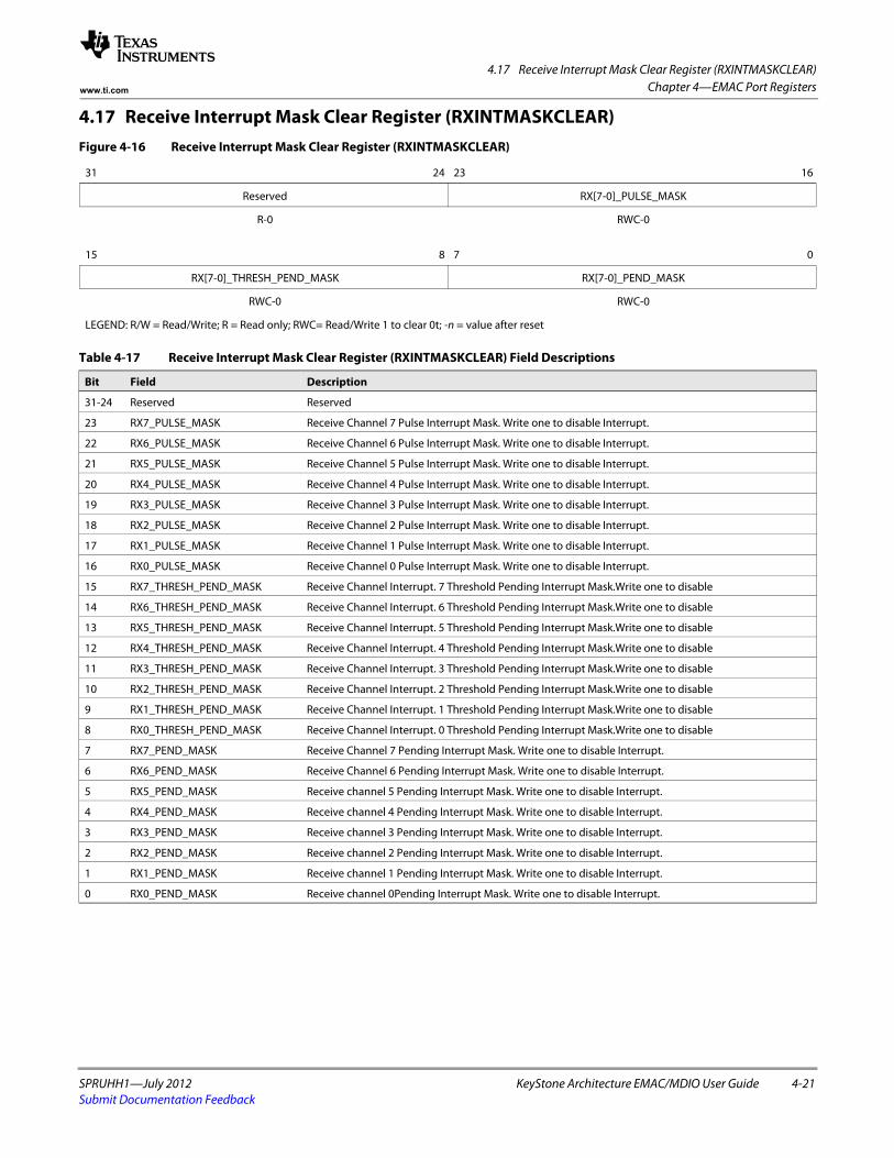
4.17 Receive Interrupt Mask Clear Register (RXINTMASKCLEAR)
SPRUHH1—July 2012 KeyStone Architecture EMAC/MDIO User Guide 4-21Submit Documentation Feedback
Chapter 4—EMAC Port Registerswww.ti.com
4.17 Receive Interrupt Mask Clear Register (RXINTMASKCLEAR)Figure 4-16 Receive Interrupt Mask Clear Register (RXINTMASKCLEAR)
31 24 23 16
Reserved RX[7-0]_PULSE_MASK
R-0 RWC-0spacer
15 8 7 0
RX[7-0]_THRESH_PEND_MASK RX[7-0]_PEND_MASK
RWC-0 RWC-0
LEGEND: R/W = Read/Write; R = Read only; RWC= Read/Write 1 to clear 0t; -n = value after reset
Table 4-17 Receive Interrupt Mask Clear Register (RXINTMASKCLEAR) Field Descriptions
Bit Field Description
31-24 Reserved Reserved
23 RX7_PULSE_MASK Receive Channel 7 Pulse Interrupt Mask. Write one to disable Interrupt.
22 RX6_PULSE_MASK Receive Channel 6 Pulse Interrupt Mask. Write one to disable Interrupt.
21 RX5_PULSE_MASK Receive Channel 5 Pulse Interrupt Mask. Write one to disable Interrupt.
20 RX4_PULSE_MASK Receive Channel 4 Pulse Interrupt Mask. Write one to disable Interrupt.
19 RX3_PULSE_MASK Receive Channel 3 Pulse Interrupt Mask. Write one to disable Interrupt.
18 RX2_PULSE_MASK Receive Channel 2 Pulse Interrupt Mask. Write one to disable Interrupt.
17 RX1_PULSE_MASK Receive Channel 1 Pulse Interrupt Mask. Write one to disable Interrupt.
16 RX0_PULSE_MASK Receive Channel 0 Pulse Interrupt Mask. Write one to disable Interrupt.
15 RX7_THRESH_PEND_MASK Receive Channel Interrupt. 7 Threshold Pending Interrupt Mask.Write one to disable
14 RX6_THRESH_PEND_MASK Receive Channel Interrupt. 6 Threshold Pending Interrupt Mask.Write one to disable
13 RX5_THRESH_PEND_MASK Receive Channel Interrupt. 5 Threshold Pending Interrupt Mask.Write one to disable
12 RX4_THRESH_PEND_MASK Receive Channel Interrupt. 4 Threshold Pending Interrupt Mask.Write one to disable
11 RX3_THRESH_PEND_MASK Receive Channel Interrupt. 3 Threshold Pending Interrupt Mask.Write one to disable
10 RX2_THRESH_PEND_MASK Receive Channel Interrupt. 2 Threshold Pending Interrupt Mask.Write one to disable
9 RX1_THRESH_PEND_MASK Receive Channel Interrupt. 1 Threshold Pending Interrupt Mask.Write one to disable
8 RX0_THRESH_PEND_MASK Receive Channel Interrupt. 0 Threshold Pending Interrupt Mask.Write one to disable
7 RX7_PEND_MASK Receive Channel 7 Pending Interrupt Mask. Write one to disable Interrupt.
6 RX6_PEND_MASK Receive Channel 6 Pending Interrupt Mask. Write one to disable Interrupt.
5 RX5_PEND_MASK Receive channel 5 Pending Interrupt Mask. Write one to disable Interrupt.
4 RX4_PEND_MASK Receive channel 4 Pending Interrupt Mask. Write one to disable Interrupt.
3 RX3_PEND_MASK Receive channel 3 Pending Interrupt Mask. Write one to disable Interrupt.
2 RX2_PEND_MASK Receive channel 2 Pending Interrupt Mask. Write one to disable Interrupt.
1 RX1_PEND_MASK Receive channel 1 Pending Interrupt Mask. Write one to disable Interrupt.
0 RX0_PEND_MASK Receive channel 0Pending Interrupt Mask. Write one to disable Interrupt.
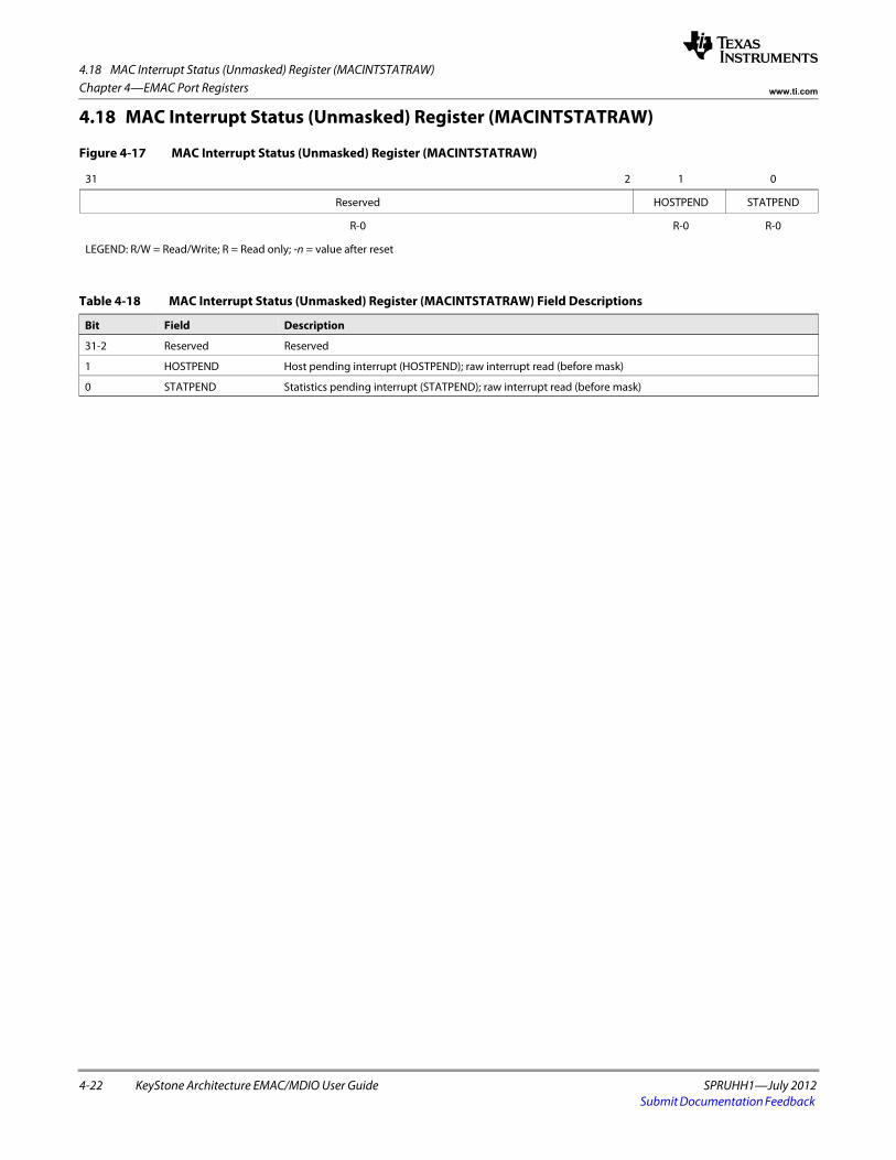
4.18 MAC Interrupt Status (Unmasked) Register (MACINTSTATRAW)
4-22 KeyStone Architecture EMAC/MDIO User Guide SPRUHH1—July 2012Submit Documentation Feedback
Chapter 4—EMAC Port Registers www.ti.com
4.18 MAC Interrupt Status (Unmasked) Register (MACINTSTATRAW)
Figure 4-17 MAC Interrupt Status (Unmasked) Register (MACINTSTATRAW)
31 2 1 0
Reserved HOSTPEND STATPEND
R-0 R-0 R-0
LEGEND: R/W = Read/Write; R = Read only; -n = value after reset
Table 4-18 MAC Interrupt Status (Unmasked) Register (MACINTSTATRAW) Field Descriptions
Bit Field Description
31-2 Reserved Reserved
1 HOSTPEND Host pending interrupt (HOSTPEND); raw interrupt read (before mask)
0 STATPEND Statistics pending interrupt (STATPEND); raw interrupt read (before mask)
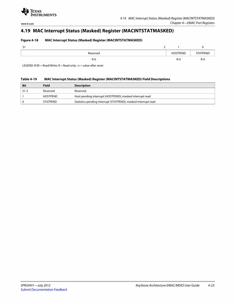
4.19 MAC Interrupt Status (Masked) Register (MACINTSTATMASKED)
SPRUHH1—July 2012 KeyStone Architecture EMAC/MDIO User Guide 4-23Submit Documentation Feedback
Chapter 4—EMAC Port Registerswww.ti.com
4.19 MAC Interrupt Status (Masked) Register (MACINTSTATMASKED)
Figure 4-18 MAC Interrupt Status (Masked) Register (MACINTSTATMASKED)
31 2 1 0
Reserved HOSTPEND STATPEND
R-0 R-0 R-0
LEGEND: R/W = Read/Write; R = Read only; -n = value after reset
Table 4-19 MAC Interrupt Status (Masked) Register (MACINTSTATMASKED) Field Descriptions
Bit Field Description
31-2 Reserved Reserved
1 HOSTPEND Host pending interrupt (HOSTPEND); masked interrupt read
0 STATPEND Statistics pending interrupt (STATPEND); masked interrupt read
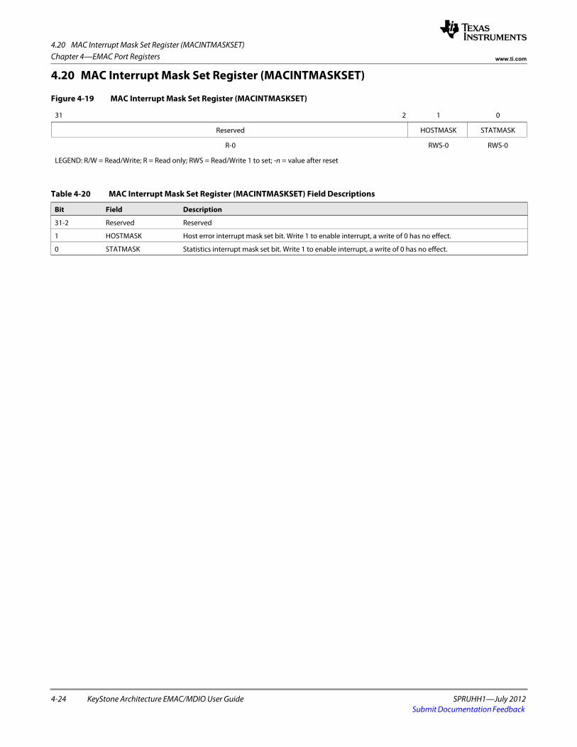
4.20 MAC Interrupt Mask Set Register (MACINTMASKSET)
4-24 KeyStone Architecture EMAC/MDIO User Guide SPRUHH1—July 2012Submit Documentation Feedback
Chapter 4—EMAC Port Registers www.ti.com
4.20 MAC Interrupt Mask Set Register (MACINTMASKSET)
Figure 4-19 MAC Interrupt Mask Set Register (MACINTMASKSET)
31 2 1 0
Reserved HOSTMASK STATMASK
R-0 RWS-0 RWS-0
LEGEND: R/W = Read/Write; R = Read only; RWS = Read/Write 1 to set; -n = value after reset
Table 4-20 MAC Interrupt Mask Set Register (MACINTMASKSET) Field Descriptions
Bit Field Description
31-2 Reserved Reserved
1 HOSTMASK Host error interrupt mask set bit. Write 1 to enable interrupt, a write of 0 has no effect.
0 STATMASK Statistics interrupt mask set bit. Write 1 to enable interrupt, a write of 0 has no effect.
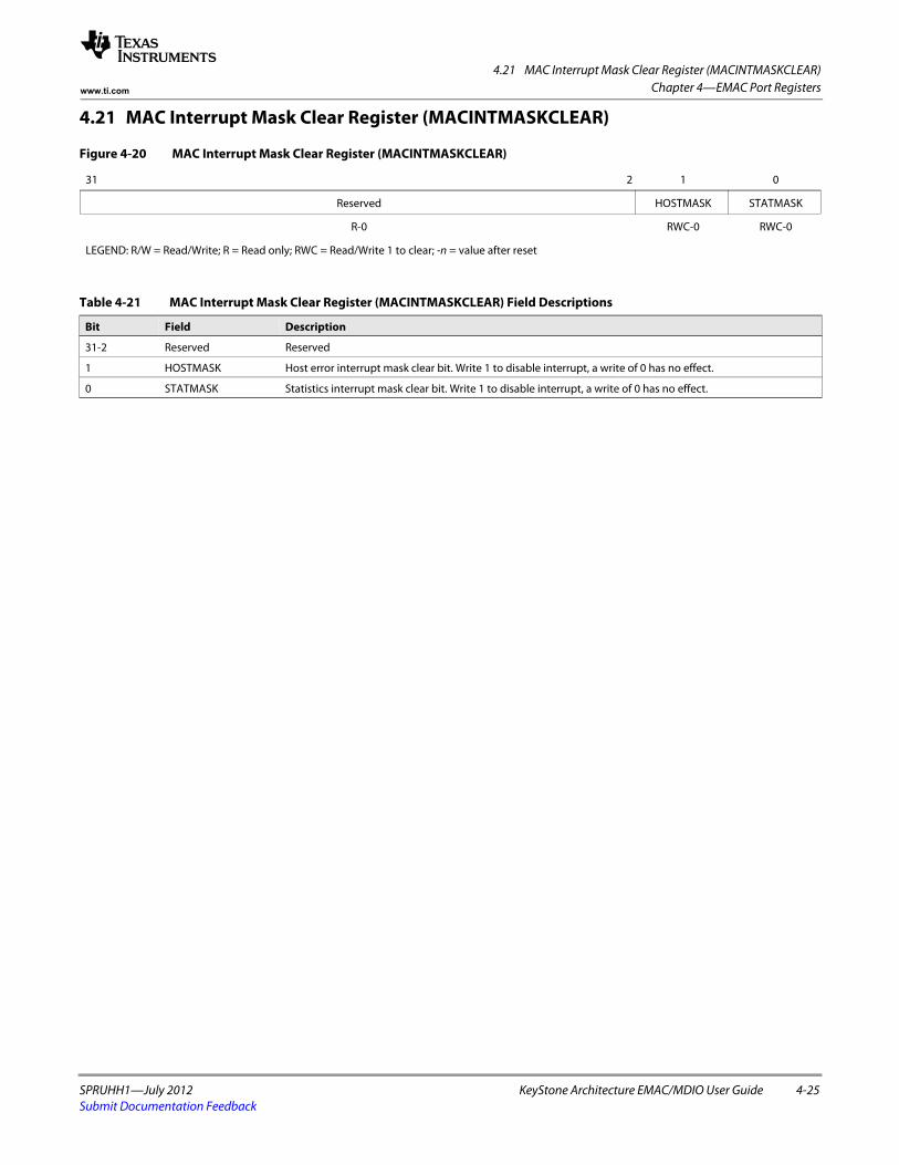
4.21 MAC Interrupt Mask Clear Register (MACINTMASKCLEAR)
SPRUHH1—July 2012 KeyStone Architecture EMAC/MDIO User Guide 4-25Submit Documentation Feedback
Chapter 4—EMAC Port Registerswww.ti.com
4.21 MAC Interrupt Mask Clear Register (MACINTMASKCLEAR)
Figure 4-20 MAC Interrupt Mask Clear Register (MACINTMASKCLEAR)
31 2 1 0
Reserved HOSTMASK STATMASK
R-0 RWC-0 RWC-0
LEGEND: R/W = Read/Write; R = Read only; RWC = Read/Write 1 to clear; -n = value after reset
Table 4-21 MAC Interrupt Mask Clear Register (MACINTMASKCLEAR) Field Descriptions
Bit Field Description
31-2 Reserved Reserved
1 HOSTMASK Host error interrupt mask clear bit. Write 1 to disable interrupt, a write of 0 has no effect.
0 STATMASK Statistics interrupt mask clear bit. Write 1 to disable interrupt, a write of 0 has no effect.
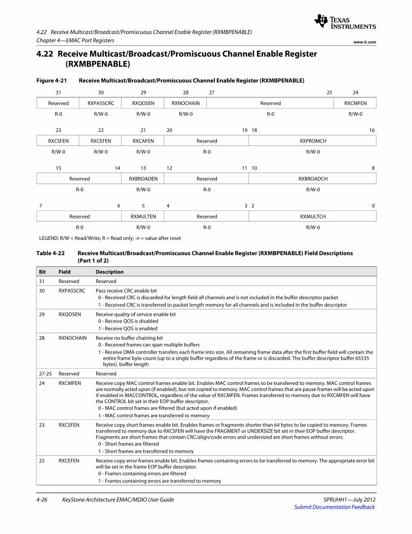
4.22 Receive Multicast/Broadcast/Promiscuous Channel Enable Register (RXMBPENABLE)
4-26 KeyStone Architecture EMAC/MDIO User Guide SPRUHH1—July 2012Submit Documentation Feedback
Chapter 4—EMAC Port Registers www.ti.com
4.22 Receive Multicast/Broadcast/Promiscuous Channel Enable Register (RXMBPENABLE)
Figure 4-21 Receive Multicast/Broadcast/Promiscuous Channel Enable Register (RXMBPENABLE)
31 30 29 28 27 25 24
Reserved RXPASSCRC RXQOSEN RXNOCHAIN Reserved RXCMFEN
R-0 R/W-0 R/W-0 R/W-0 R-0 R/W-0
23 22 21 20 19 18 16
RXCSFEN RXCEFEN RXCAFEN Reserved RXPROMCH
R/W-0 R/W-0 R/W-0 R-0 R/W-0
15 14 13 12 11 10 8
Reserved RXBROADEN Reserved RXBROADCH
R-0 R/W-0 R-0 R/W-0
7 6 5 4 3 2 0
Reserved RXMULTEN Reserved RXMULTCH
R-0 R/W-0 R-0 R/W-0
LEGEND: R/W = Read/Write; R = Read only; -n = value after reset
Table 4-22 Receive Multicast/Broadcast/Promiscuous Channel Enable Register (RXMBPENABLE) Field Descriptions (Part 1 of 2)
Bit Field Description
31 Reserved Reserved
30 RXPASSCRC Pass receive CRC enable bit 0 - Received CRC is discarded for length field all channels and is not included in the buffer descriptor packet 1 - Received CRC is transferred to packet length memory for all channels and is included in the buffer descriptor
29 RXQOSEN Receive quality of service enable bit 0 - Receive QOS is disabled 1 - Receive QOS is enabled
28 RXNOCHAIN Receive no buffer chaining bit 0 - Received frames can span multiple buffers 1 - Receive DMA controller transfers each frame into size. All remaining frame data after the first buffer field will contain the
entire frame byte count (up to a single buffer regardless of the frame or is discarded. The buffer descriptor buffer 65535 bytes). buffer length
27-25 Reserved Reserved
24 RXCMFEN Receive copy MAC control frames enable bit. Enables MAC control frames to be transferred to memory. MAC control frames are normally acted upon (if enabled), but not copied to memory. MAC control frames that are pause frames will be acted upon if enabled in MACCONTROL, regardless of the value of RXCMFEN. Frames transferred to memory due to RXCMFEN will have the CONTROL bit set in their EOP buffer descriptor.
0 - MAC control frames are filtered (but acted upon if enabled) 1 - MAC control frames are transferred to memory
23 RXCSFEN Receive copy short frames enable bit. Enables frames or fragments shorter than 64 bytes to be copied to memory. Frames transferred to memory due to RXCSFEN will have the FRAGMENT or UNDERSIZE bit set in their EOP buffer descriptor. Fragments are short frames that contain CRC/align/code errors and undersized are short frames without errors.
0 - Short frames are filtered 1 - Short frames are transferred to memory
22 RXCEFEN Receive copy error frames enable bit. Enables frames containing errors to be transferred to memory. The appropriate error bit will be set in the frame EOP buffer descriptor.
0 - Frames containing errors are filtered 1 - Frames containing errors are transferred to memory
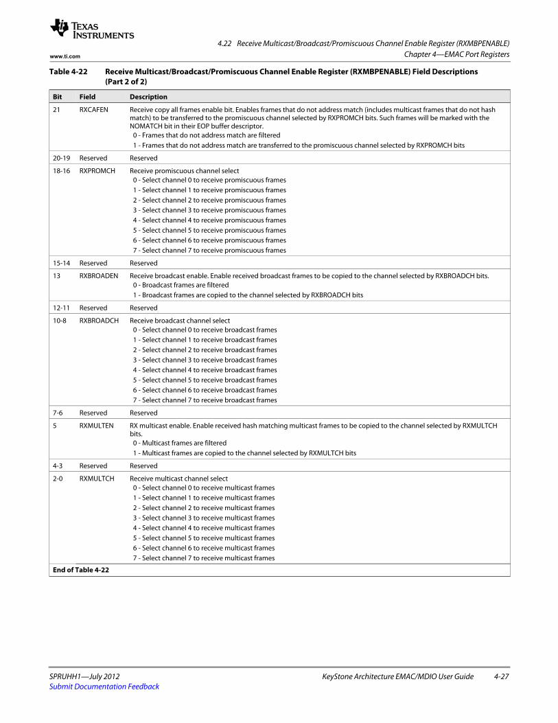
4.22 Receive Multicast/Broadcast/Promiscuous Channel Enable Register (RXMBPENABLE)
SPRUHH1—July 2012 KeyStone Architecture EMAC/MDIO User Guide 4-27Submit Documentation Feedback
Chapter 4—EMAC Port Registerswww.ti.com
21 RXCAFEN Receive copy all frames enable bit. Enables frames that do not address match (includes multicast frames that do not hash match) to be transferred to the promiscuous channel selected by RXPROMCH bits. Such frames will be marked with the NOMATCH bit in their EOP buffer descriptor.
0 - Frames that do not address match are filtered 1 - Frames that do not address match are transferred to the promiscuous channel selected by RXPROMCH bits
20-19 Reserved Reserved
18-16 RXPROMCH Receive promiscuous channel select 0 - Select channel 0 to receive promiscuous frames 1 - Select channel 1 to receive promiscuous frames 2 - Select channel 2 to receive promiscuous frames 3 - Select channel 3 to receive promiscuous frames 4 - Select channel 4 to receive promiscuous frames 5 - Select channel 5 to receive promiscuous frames 6 - Select channel 6 to receive promiscuous frames 7 - Select channel 7 to receive promiscuous frames
15-14 Reserved Reserved
13 RXBROADEN Receive broadcast enable. Enable received broadcast frames to be copied to the channel selected by RXBROADCH bits. 0 - Broadcast frames are filtered 1 - Broadcast frames are copied to the channel selected by RXBROADCH bits
12-11 Reserved Reserved
10-8 RXBROADCH Receive broadcast channel select 0 - Select channel 0 to receive broadcast frames 1 - Select channel 1 to receive broadcast frames 2 - Select channel 2 to receive broadcast frames 3 - Select channel 3 to receive broadcast frames 4 - Select channel 4 to receive broadcast frames 5 - Select channel 5 to receive broadcast frames 6 - Select channel 6 to receive broadcast frames 7 - Select channel 7 to receive broadcast frames
7-6 Reserved Reserved
5 RXMULTEN RX multicast enable. Enable received hash matching multicast frames to be copied to the channel selected by RXMULTCH bits.
0 - Multicast frames are filtered 1 - Multicast frames are copied to the channel selected by RXMULTCH bits
4-3 Reserved Reserved
2-0 RXMULTCH Receive multicast channel select 0 - Select channel 0 to receive multicast frames 1 - Select channel 1 to receive multicast frames 2 - Select channel 2 to receive multicast frames 3 - Select channel 3 to receive multicast frames 4 - Select channel 4 to receive multicast frames 5 - Select channel 5 to receive multicast frames 6 - Select channel 6 to receive multicast frames 7 - Select channel 7 to receive multicast frames
End of Table 4-22
Table 4-22 Receive Multicast/Broadcast/Promiscuous Channel Enable Register (RXMBPENABLE) Field Descriptions (Part 2 of 2)
Bit Field Description
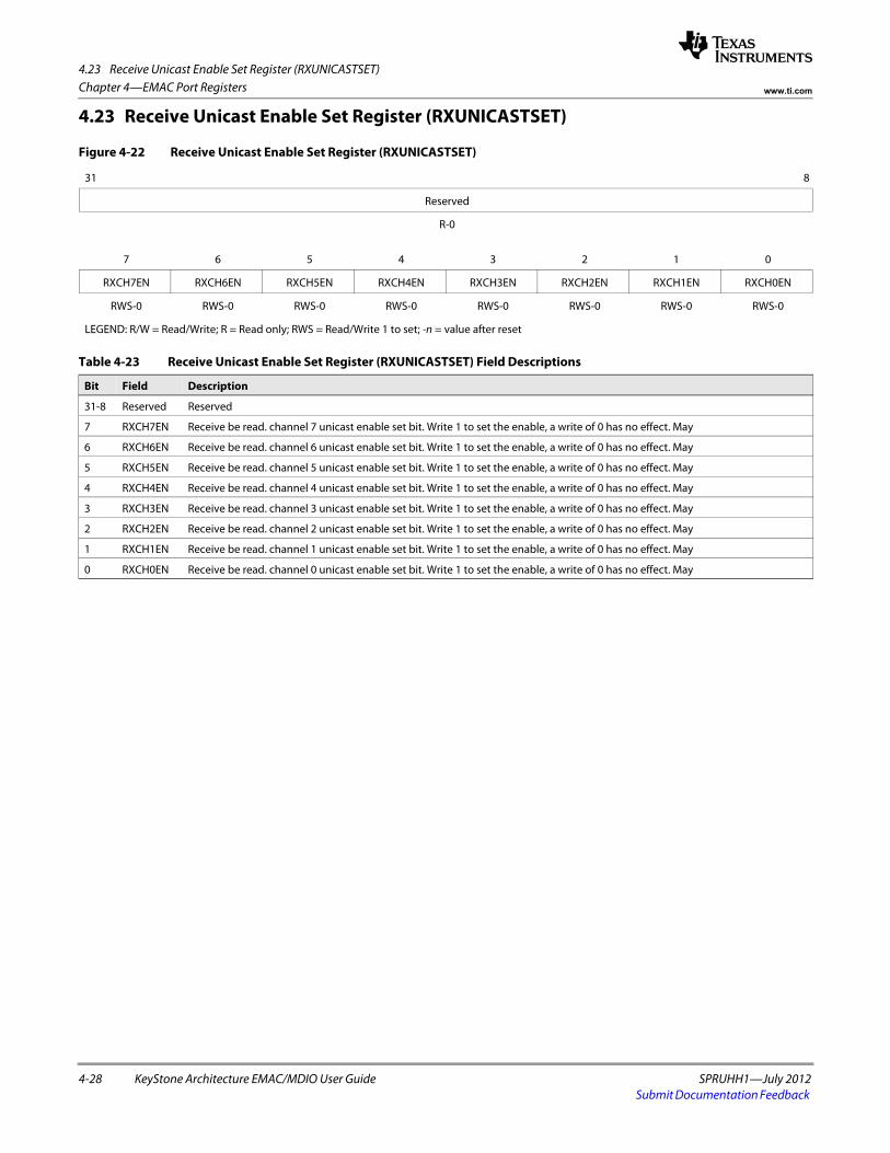
4.23 Receive Unicast Enable Set Register (RXUNICASTSET)
4-28 KeyStone Architecture EMAC/MDIO User Guide SPRUHH1—July 2012Submit Documentation Feedback
Chapter 4—EMAC Port Registers www.ti.com
4.23 Receive Unicast Enable Set Register (RXUNICASTSET)
Figure 4-22 Receive Unicast Enable Set Register (RXUNICASTSET)
31 8
Reserved
R-0spacer
7 6 5 4 3 2 1 0
RXCH7EN RXCH6EN RXCH5EN RXCH4EN RXCH3EN RXCH2EN RXCH1EN RXCH0EN
RWS-0 RWS-0 RWS-0 RWS-0 RWS-0 RWS-0 RWS-0 RWS-0
LEGEND: R/W = Read/Write; R = Read only; RWS = Read/Write 1 to set; -n = value after reset
Table 4-23 Receive Unicast Enable Set Register (RXUNICASTSET) Field Descriptions
Bit Field Description
31-8 Reserved Reserved
7 RXCH7EN Receive be read. channel 7 unicast enable set bit. Write 1 to set the enable, a write of 0 has no effect. May
6 RXCH6EN Receive be read. channel 6 unicast enable set bit. Write 1 to set the enable, a write of 0 has no effect. May
5 RXCH5EN Receive be read. channel 5 unicast enable set bit. Write 1 to set the enable, a write of 0 has no effect. May
4 RXCH4EN Receive be read. channel 4 unicast enable set bit. Write 1 to set the enable, a write of 0 has no effect. May
3 RXCH3EN Receive be read. channel 3 unicast enable set bit. Write 1 to set the enable, a write of 0 has no effect. May
2 RXCH2EN Receive be read. channel 2 unicast enable set bit. Write 1 to set the enable, a write of 0 has no effect. May
1 RXCH1EN Receive be read. channel 1 unicast enable set bit. Write 1 to set the enable, a write of 0 has no effect. May
0 RXCH0EN Receive be read. channel 0 unicast enable set bit. Write 1 to set the enable, a write of 0 has no effect. May
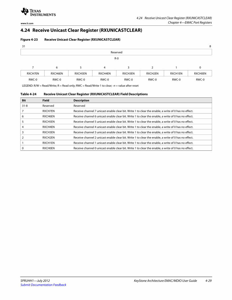
4.24 Receive Unicast Clear Register (RXUNICASTCLEAR)
SPRUHH1—July 2012 KeyStone Architecture EMAC/MDIO User Guide 4-29Submit Documentation Feedback
Chapter 4—EMAC Port Registerswww.ti.com
4.24 Receive Unicast Clear Register (RXUNICASTCLEAR)
Figure 4-23 Receive Unicast Clear Register (RXUNICASTCLEAR)
31 8
Reserved
R-0spacer
7 6 5 4 3 2 1 0
RXCH7EN RXCH6EN RXCH5EN RXCH4EN RXCH3EN RXCH2EN RXCH1EN RXCH0EN
RWC-0 RWC-0 RWC-0 RWC-0 RWC-0 RWC-0 RWC-0 RWC-0
LEGEND: R/W = Read/Write; R = Read only; RWC = Read/Write 1 to clear; -n = value after reset
Table 4-24 Receive Unicast Clear Register (RXUNICASTCLEAR) Field Descriptions
Bit Field Description
31-8 Reserved Reserved
7 RXCH7EN Receive channel 7 unicast enable clear bit. Write 1 to clear the enable, a write of 0 has no effect.
6 RXCH6EN Receive channel 6 unicast enable clear bit. Write 1 to clear the enable, a write of 0 has no effect.
5 RXCH5EN Receive channel 5 unicast enable clear bit. Write 1 to clear the enable, a write of 0 has no effect.
4 RXCH4EN Receive channel 4 unicast enable clear bit. Write 1 to clear the enable, a write of 0 has no effect.
3 RXCH3EN Receive channel 3 unicast enable clear bit. Write 1 to clear the enable, a write of 0 has no effect.
2 RXCH2EN Receive channel 2 unicast enable clear bit. Write 1 to clear the enable, a write of 0 has no effect.
1 RXCH1EN Receive channel 1 unicast enable clear bit. Write 1 to clear the enable, a write of 0 has no effect.
0 RXCH0EN Receive channel 0 unicast enable clear bit. Write 1 to clear the enable, a write of 0 has no effect.
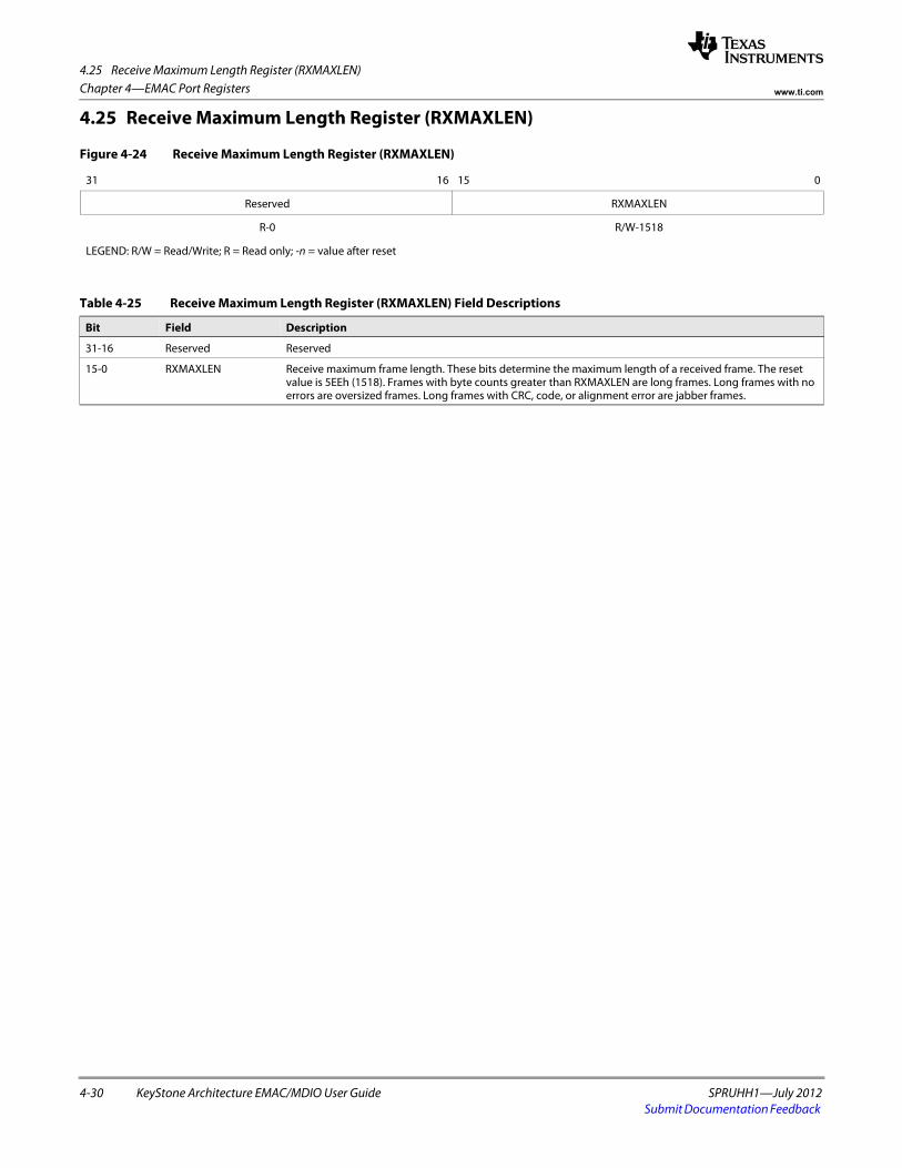
4.25 Receive Maximum Length Register (RXMAXLEN)
4-30 KeyStone Architecture EMAC/MDIO User Guide SPRUHH1—July 2012Submit Documentation Feedback
Chapter 4—EMAC Port Registers www.ti.com
4.25 Receive Maximum Length Register (RXMAXLEN)
Figure 4-24 Receive Maximum Length Register (RXMAXLEN)
31 16 15 0
Reserved RXMAXLEN
R-0 R/W-1518
LEGEND: R/W = Read/Write; R = Read only; -n = value after reset
Table 4-25 Receive Maximum Length Register (RXMAXLEN) Field Descriptions
Bit Field Description
31-16 Reserved Reserved
15-0 RXMAXLEN Receive maximum frame length. These bits determine the maximum length of a received frame. The reset value is 5EEh (1518). Frames with byte counts greater than RXMAXLEN are long frames. Long frames with no errors are oversized frames. Long frames with CRC, code, or alignment error are jabber frames.
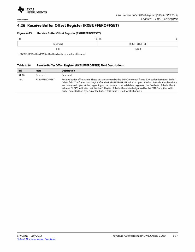
4.26 Receive Buffer Offset Register (RXBUFFEROFFSET)
SPRUHH1—July 2012 KeyStone Architecture EMAC/MDIO User Guide 4-31Submit Documentation Feedback
Chapter 4—EMAC Port Registerswww.ti.com
4.26 Receive Buffer Offset Register (RXBUFFEROFFSET)
Figure 4-25 Receive Buffer Offset Register (RXBUFFEROFFSET)
31 16 15 0
Reserved RXBUFFEROFFSET
R-0 R/W-0
LEGEND: R/W = Read/Write; R = Read only; -n = value after reset
Table 4-26 Receive Buffer Offset Register (RXBUFFEROFFSET) Field Descriptions
Bit Field Description
31-16 Reserved Reserved
15-0 RXBUFFEROFFSET Receive buffer offset value. These bits are written by the EMAC into each frame SOP buffer descriptor Buffer Offset field. The frame data begins after the RXBUFFEROFFSET value of bytes. A value of 0 indicates that there are no unused bytes at the beginning of the data and that valid data begins on the first byte of the buffer. A value of Fh (15) indicates that the first 15 bytes of the buffer are to be ignored by the EMAC and that valid buffer data starts on byte 16 of the buffer. This value is used for all channels.
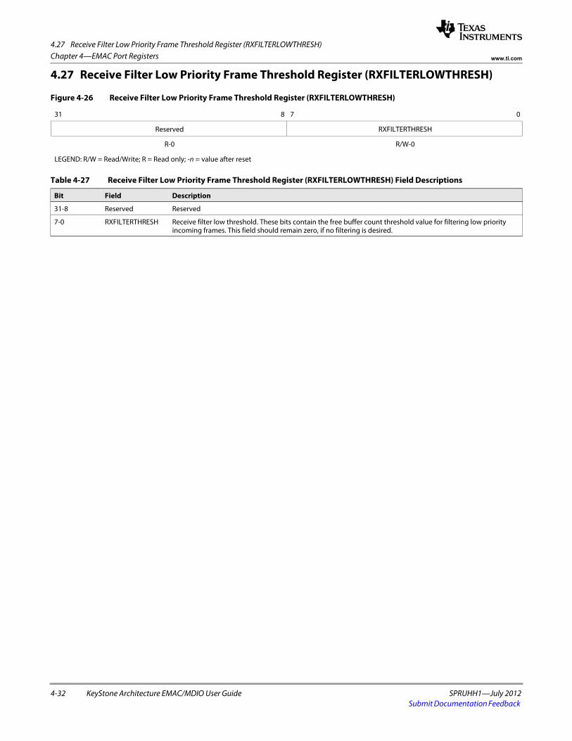
4.27 Receive Filter Low Priority Frame Threshold Register (RXFILTERLOWTHRESH)
4-32 KeyStone Architecture EMAC/MDIO User Guide SPRUHH1—July 2012Submit Documentation Feedback
Chapter 4—EMAC Port Registers www.ti.com
4.27 Receive Filter Low Priority Frame Threshold Register (RXFILTERLOWTHRESH)
Figure 4-26 Receive Filter Low Priority Frame Threshold Register (RXFILTERLOWTHRESH)
31 8 7 0
Reserved RXFILTERTHRESH
R-0 R/W-0
LEGEND: R/W = Read/Write; R = Read only; -n = value after reset
Table 4-27 Receive Filter Low Priority Frame Threshold Register (RXFILTERLOWTHRESH) Field Descriptions
Bit Field Description
31-8 Reserved Reserved
7-0 RXFILTERTHRESH Receive filter low threshold. These bits contain the free buffer count threshold value for filtering low priority incoming frames. This field should remain zero, if no filtering is desired.
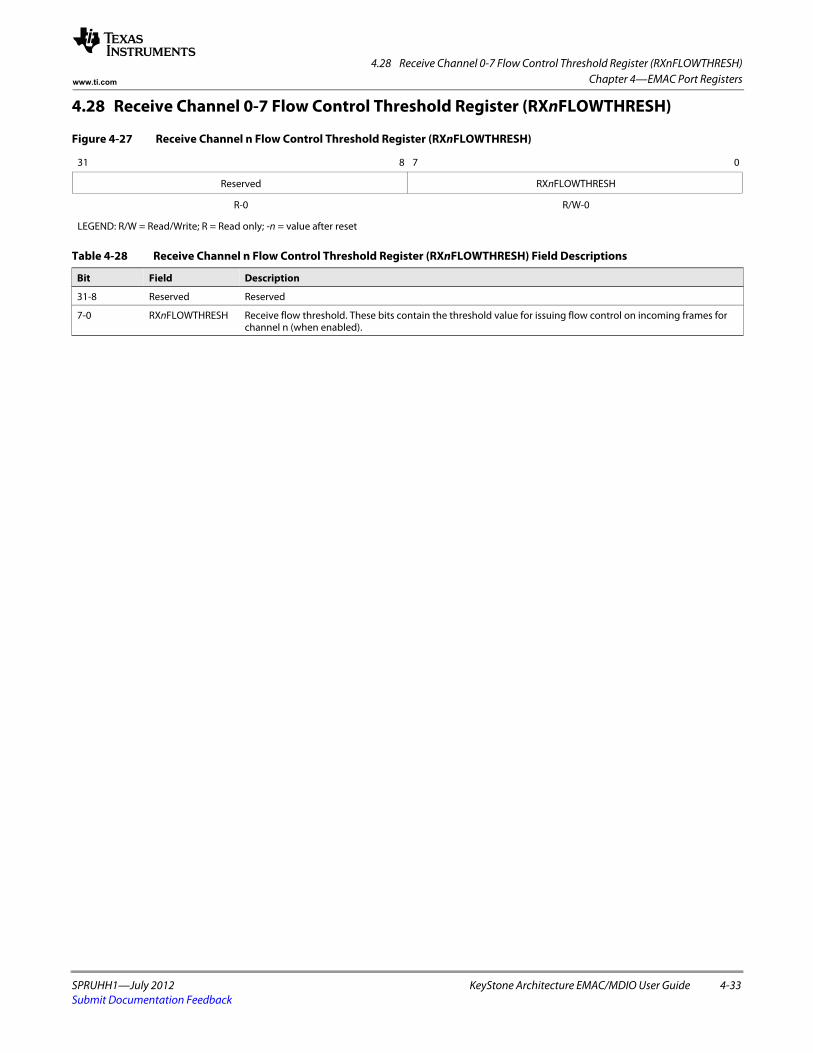
4.28 Receive Channel 0-7 Flow Control Threshold Register (RXnFLOWTHRESH)
SPRUHH1—July 2012 KeyStone Architecture EMAC/MDIO User Guide 4-33Submit Documentation Feedback
Chapter 4—EMAC Port Registerswww.ti.com
4.28 Receive Channel 0-7 Flow Control Threshold Register (RXnFLOWTHRESH)
Figure 4-27 Receive Channel n Flow Control Threshold Register (RXnFLOWTHRESH)
31 8 7 0
Reserved RXnFLOWTHRESH
R-0 R/W-0
LEGEND: R/W = Read/Write; R = Read only; -n = value after reset
Table 4-28 Receive Channel n Flow Control Threshold Register (RXnFLOWTHRESH) Field Descriptions
Bit Field Description
31-8 Reserved Reserved
7-0 RXnFLOWTHRESH Receive flow threshold. These bits contain the threshold value for issuing flow control on incoming frames for channel n (when enabled).
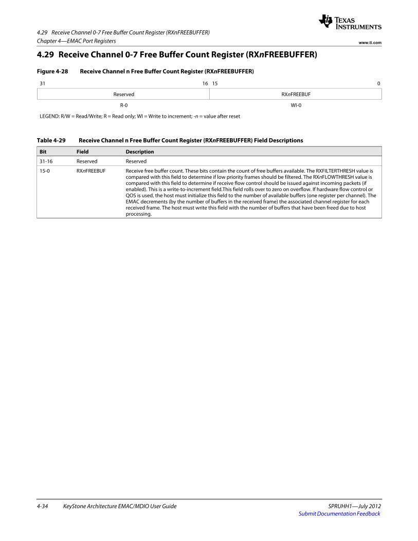
4.29 Receive Channel 0-7 Free Buffer Count Register (RXnFREEBUFFER)
4-34 KeyStone Architecture EMAC/MDIO User Guide SPRUHH1—July 2012Submit Documentation Feedback
Chapter 4—EMAC Port Registers www.ti.com
4.29 Receive Channel 0-7 Free Buffer Count Register (RXnFREEBUFFER)
Figure 4-28 Receive Channel n Free Buffer Count Register (RXnFREEBUFFER)
31 16 15 0
Reserved RXnFREEBUF
R-0 WI-0
LEGEND: R/W = Read/Write; R = Read only; WI = Write to increment; -n = value after reset
Table 4-29 Receive Channel n Free Buffer Count Register (RXnFREEBUFFER) Field Descriptions
Bit Field Description
31-16 Reserved Reserved
15-0 RXnFREEBUF Receive free buffer count. These bits contain the count of free buffers available. The RXFILTERTHRESH value is compared with this field to determine if low priority frames should be filtered. The RXnFLOWTHRESH value is compared with this field to determine if receive flow control should be issued against incoming packets (if enabled). This is a write-to-increment field.This field rolls over to zero on overflow. If hardware flow control or QOS is used, the host must initialize this field to the number of available buffers (one register per channel). The EMAC decrements (by the number of buffers in the received frame) the associated channel register for each received frame. The host must write this field with the number of buffers that have been freed due to host processing.
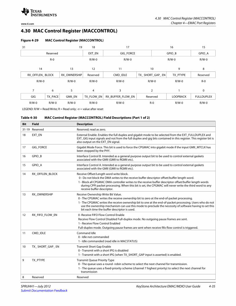
4.30 MAC Control Register (MACCONTROL)
SPRUHH1—July 2012 KeyStone Architecture EMAC/MDIO User Guide 4-35Submit Documentation Feedback
Chapter 4—EMAC Port Registerswww.ti.com
4.30 MAC Control Register (MACCONTROL)
Figure 4-29 MAC Control Register (MACCONTROL)
31 19 18 17 16 15
Reserved EXT_EN GIG_FORCE GPIO_B GPIO_A
R-0 R/W-0 R/W-0 R/W-0 R/W-0spacer
14 13 12 11 10 9 8
RX_OFFLEN_ BLOCK RX_OWNERSHIP Reserved CMD_IDLE TX_ SHORT_GAP_ EN TX_PTYPE Reserved
R/W-0 R/W-0 R/W-0 R/W-0 R/W-0 R/W-0 R-0spacer
7 6 5 4 3 2 1 0
GIG TX_PACE GMII_EN TX_FLOW_EN RX_BUFFER_FLOW_EN Reserved LOOPBACK FULLDUPLEX
R/W-0 R/W-0 R/W-0 R/W-0 R/W-0 R-0 R/W-0 R/W-0
LEGEND: R/W = Read/Write; R = Read only; -n = value after reset
Table 4-30 MAC Control Register (MACCONTROL) Field Descriptions (Part 1 of 2)
Bit Field Description
31-19 Reserved Reserved; read as zero.
18 EXT_EN External Enable. Enables the full duplex and gigabit mode to be selected from the EXT_FULLDUPLEX and EXT_GIG input signals and not from the full duplex and gig bits contained in this register. This register bit is also output on the EXT_EN signal.
17 GIG_FORCE Gigabit Mode Force. This bit is used to force the CPGMAC into gigabit mode if the input GMII_MTCLK has been stopped by the PHY.
16 GPIO_B Interface Control B. Intended as a general purpose output bit to be used to control external gaskets associated with the GMII (GMII to RGMII etc).
15 GPIO_A Interface Control A. Intended as a general purpose output bit to be used to control external gaskets associated with the GMII (GMII to RGMII etc).
14 RX_OFFLEN_BLOCK Receive Offset/Length word write block. 0 - Do not block the DMA writes to the receive buffer descriptor offset/buffer length word.1 - Block all CPGMAC DMA controller writes to the receive buffer descriptor offset/buffer length words
during CPPI packet processing. When this bit is set, the CPGMAC will never write the third word to any receive buffer descriptor.
13 RX_OWNERSHIP Receive Ownership Write Bit Value.0 - The CPGMAC writes the receive ownership bit to zero at the end-of-packet processing.1 - The CPGMAC writes the receive ownership bit to one at the end-of-packet processing. Users who do not
use the ownership mechanism can use this mode to preclude the necessity of software having to set this bit each time the buffer descriptor is used.
12 RX_FIFO_FLOW_EN 0 -Receive FIFO Flow Control EnableReceive Flow Control Disabled Full-duplex mode. No outgoing pause frames are sent.1 - Receive Flow Control EnabledFull-duplex mode. Outgoing pause frames are sent when receive fifo flow control is triggered.
11 CMD_IDLE Command Idle0 - Idle not commanded1 - Idle commanded (read idle in MACSTATUS)
10 TX_ SHORT_GAP_ EN Transmit Short Gap Enable0 - Transmit with a short IPG is disabled1 - Transmit with a short IPG (when TX_SHORT_GAP input is asserted) is enabled.
9 TX_PTYPE Transmit Queue Priority Type0 - The queue uses a round- robin scheme to select the next channel for transmission.1 - The queue uses a fixed-priority scheme (channel 7 highest priority) to select the next channel for
transmission
8 Reserved Reserved
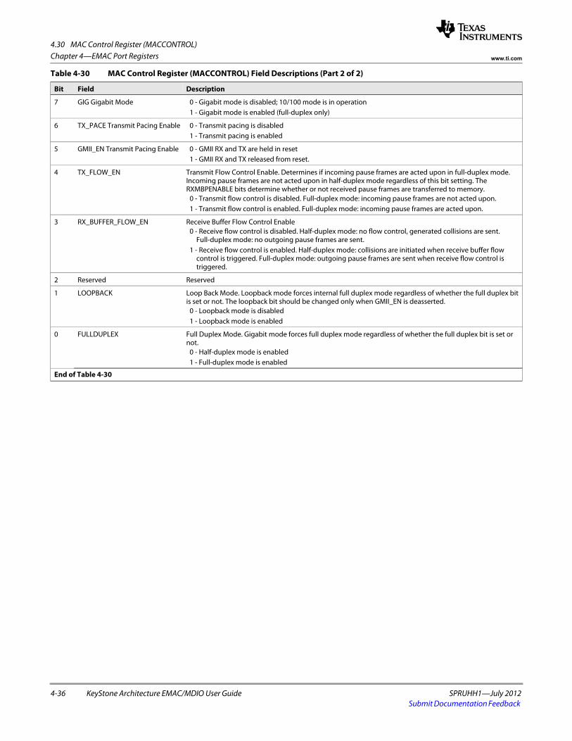
4.30 MAC Control Register (MACCONTROL)
4-36 KeyStone Architecture EMAC/MDIO User Guide SPRUHH1—July 2012Submit Documentation Feedback
Chapter 4—EMAC Port Registers www.ti.com
7 GIG Gigabit Mode 0 - Gigabit mode is disabled; 10/100 mode is in operation1 - Gigabit mode is enabled (full-duplex only)
6 TX_PACE Transmit Pacing Enable 0 - Transmit pacing is disabled1 - Transmit pacing is enabled
5 GMII_EN Transmit Pacing Enable 0 - GMII RX and TX are held in reset1 - GMII RX and TX released from reset.
4 TX_FLOW_EN Transmit Flow Control Enable. Determines if incoming pause frames are acted upon in full-duplex mode. Incoming pause frames are not acted upon in half-duplex mode regardless of this bit setting. The RXMBPENABLE bits determine whether or not received pause frames are transferred to memory.
0 - Transmit flow control is disabled. Full-duplex mode: incoming pause frames are not acted upon.1 - Transmit flow control is enabled. Full-duplex mode: incoming pause frames are acted upon.
3 RX_BUFFER_FLOW_EN Receive Buffer Flow Control Enable0 - Receive flow control is disabled. Half-duplex mode: no flow control, generated collisions are sent.
Full-duplex mode: no outgoing pause frames are sent.1 - Receive flow control is enabled. Half-duplex mode: collisions are initiated when receive buffer flow
control is triggered. Full-duplex mode: outgoing pause frames are sent when receive flow control is triggered.
2 Reserved Reserved
1 LOOPBACK Loop Back Mode. Loopback mode forces internal full duplex mode regardless of whether the full duplex bit is set or not. The loopback bit should be changed only when GMII_EN is deasserted.
0 - Loopback mode is disabled1 - Loopback mode is enabled
0 FULLDUPLEX Full Duplex Mode. Gigabit mode forces full duplex mode regardless of whether the full duplex bit is set or not.
0 - Half-duplex mode is enabled1 - Full-duplex mode is enabled
End of Table 4-30
Table 4-30 MAC Control Register (MACCONTROL) Field Descriptions (Part 2 of 2)
Bit Field Description
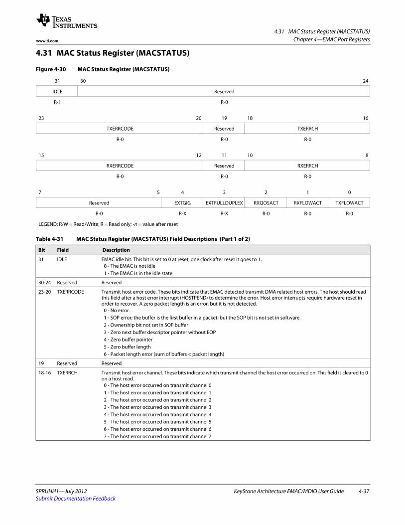
4.31 MAC Status Register (MACSTATUS)
SPRUHH1—July 2012 KeyStone Architecture EMAC/MDIO User Guide 4-37Submit Documentation Feedback
Chapter 4—EMAC Port Registerswww.ti.com
4.31 MAC Status Register (MACSTATUS)
Figure 4-30 MAC Status Register (MACSTATUS)
31 30 24
IDLE Reserved
R-1 R-0spacer
23 20 19 18 16
TXERRCODE Reserved TXERRCH
R-0 R-0 R-0spacer
15 12 11 10 8
RXERRCODE Reserved RXERRCH
R-0 R-0 R-0spacer
7 5 4 3 2 1 0
Reserved EXTGIG EXTFULLDUPLEX RXQOSACT RXFLOWACT TXFLOWACT
R-0 R-X R-X R-0 R-0 R-0
LEGEND: R/W = Read/Write; R = Read only; -n = value after reset
Table 4-31 MAC Status Register (MACSTATUS) Field Descriptions (Part 1 of 2)
Bit Field Description
31 IDLE EMAC idle bit. This bit is set to 0 at reset; one clock after reset it goes to 1.0 - The EMAC is not idle1 - The EMAC is in the idle state
30-24 Reserved Reserved
23-20 TXERRCODE Transmit host error code. These bits indicate that EMAC detected transmit DMA related host errors. The host should read this field after a host error interrupt (HOSTPEND) to determine the error. Host error interrupts require hardware reset in order to recover. A zero packet length is an error, but it is not detected.
0 - No error1 - SOP error; the buffer is the first buffer in a packet, but the SOP bit is not set in software.2 - Ownership bit not set in SOP buffer3 - Zero next buffer descriptor pointer without EOP4 - Zero buffer pointer5 - Zero buffer length6 - Packet length error (sum of buffers < packet length)
19 Reserved Reserved
18-16 TXERRCH Transmit host error channel. These bits indicate which transmit channel the host error occurred on. This field is cleared to 0 on a host read.
0 - The host error occurred on transmit channel 01 - The host error occurred on transmit channel 12 - The host error occurred on transmit channel 23 - The host error occurred on transmit channel 34 - The host error occurred on transmit channel 45 - The host error occurred on transmit channel 56 - The host error occurred on transmit channel 67 - The host error occurred on transmit channel 7
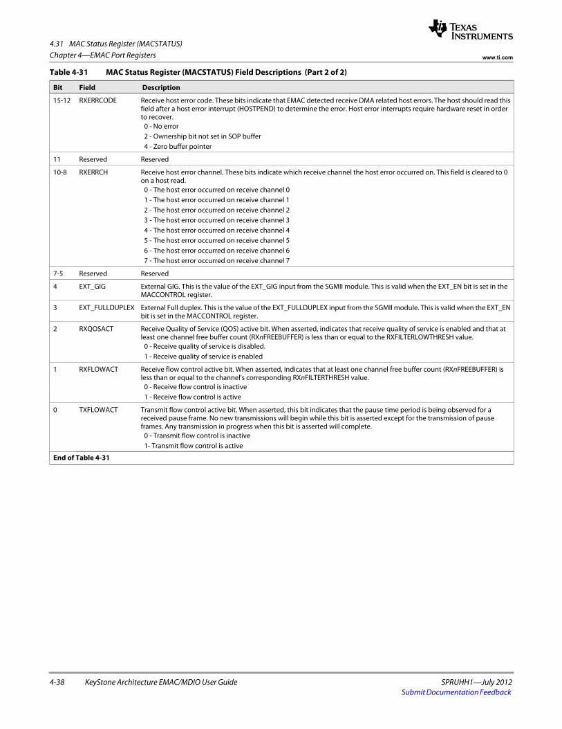
4.31 MAC Status Register (MACSTATUS)
4-38 KeyStone Architecture EMAC/MDIO User Guide SPRUHH1—July 2012Submit Documentation Feedback
Chapter 4—EMAC Port Registers www.ti.com
15-12 RXERRCODE Receive host error code. These bits indicate that EMAC detected receive DMA related host errors. The host should read this field after a host error interrupt (HOSTPEND) to determine the error. Host error interrupts require hardware reset in order to recover.
0 - No error2 - Ownership bit not set in SOP buffer4 - Zero buffer pointer
11 Reserved Reserved
10-8 RXERRCH Receive host error channel. These bits indicate which receive channel the host error occurred on. This field is cleared to 0 on a host read.
0 - The host error occurred on receive channel 01 - The host error occurred on receive channel 12 - The host error occurred on receive channel 23 - The host error occurred on receive channel 34 - The host error occurred on receive channel 45 - The host error occurred on receive channel 56 - The host error occurred on receive channel 67 - The host error occurred on receive channel 7
7-5 Reserved Reserved
4 EXT_GIG External GIG. This is the value of the EXT_GIG input from the SGMII module. This is valid when the EXT_EN bit is set in the MACCONTROL register.
3 EXT_FULLDUPLEX External Full duplex. This is the value of the EXT_FULLDUPLEX input from the SGMII module. This is valid when the EXT_EN bit is set in the MACCONTROL register.
2 RXQOSACT Receive Quality of Service (QOS) active bit. When asserted, indicates that receive quality of service is enabled and that at least one channel free buffer count (RXnFREEBUFFER) is less than or equal to the RXFILTERLOWTHRESH value.
0 - Receive quality of service is disabled.1 - Receive quality of service is enabled
1 RXFLOWACT Receive flow control active bit. When asserted, indicates that at least one channel free buffer count (RXnFREEBUFFER) is less than or equal to the channel's corresponding RXnFILTERTHRESH value.
0 - Receive flow control is inactive1 - Receive flow control is active
0 TXFLOWACT Transmit flow control active bit. When asserted, this bit indicates that the pause time period is being observed for a received pause frame. No new transmissions will begin while this bit is asserted except for the transmission of pause frames. Any transmission in progress when this bit is asserted will complete.
0 - Transmit flow control is inactive1- Transmit flow control is active
End of Table 4-31
Table 4-31 MAC Status Register (MACSTATUS) Field Descriptions (Part 2 of 2)
Bit Field Description
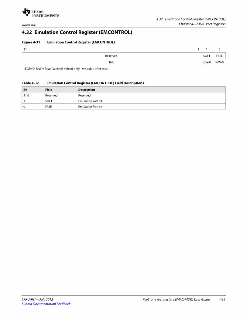
4.32 Emulation Control Register (EMCONTROL)
SPRUHH1—July 2012 KeyStone Architecture EMAC/MDIO User Guide 4-39Submit Documentation Feedback
Chapter 4—EMAC Port Registerswww.ti.com
4.32 Emulation Control Register (EMCONTROL)
Figure 4-31 Emulation Control Register (EMCONTROL)
31 2 1 0
Reserved SOFT FREE
R-0 R/W-0 R/W-0
LEGEND: R/W = Read/Write; R = Read only; -n = value after reset
Table 4-32 Emulation Control Register (EMCONTROL) Field Descriptions
Bit Field Description
31-2 Reserved Reserved
1 SOFT Emulation soft bit
0 FREE Emulation free bit
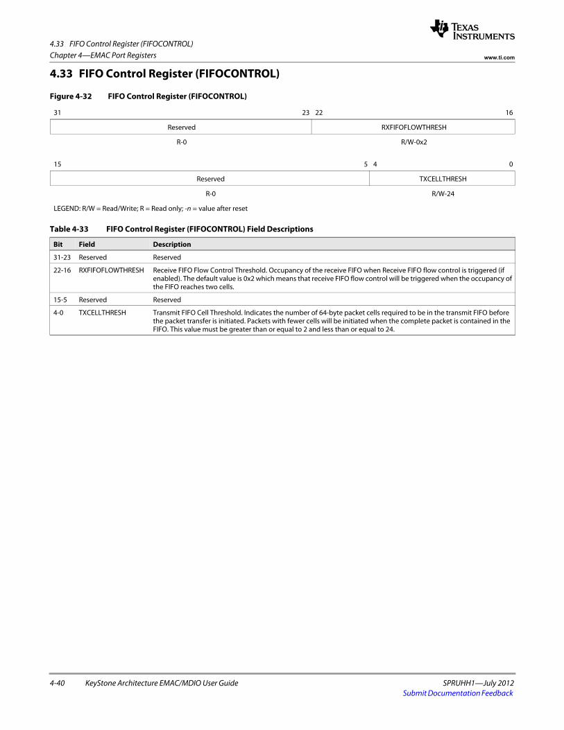
4.33 FIFO Control Register (FIFOCONTROL)
4-40 KeyStone Architecture EMAC/MDIO User Guide SPRUHH1—July 2012Submit Documentation Feedback
Chapter 4—EMAC Port Registers www.ti.com
4.33 FIFO Control Register (FIFOCONTROL)
Figure 4-32 FIFO Control Register (FIFOCONTROL)
31 23 22 16
Reserved RXFIFOFLOWTHRESH
R-0 R/W-0x2spacer
15 5 4 0
Reserved TXCELLTHRESH
R-0 R/W-24
LEGEND: R/W = Read/Write; R = Read only; -n = value after reset
Table 4-33 FIFO Control Register (FIFOCONTROL) Field Descriptions
Bit Field Description
31-23 Reserved Reserved
22-16 RXFIFOFLOWTHRESH Receive FIFO Flow Control Threshold. Occupancy of the receive FIFO when Receive FIFO flow control is triggered (if enabled). The default value is 0x2 which means that receive FIFO flow control will be triggered when the occupancy of the FIFO reaches two cells.
15-5 Reserved Reserved
4-0 TXCELLTHRESH Transmit FIFO Cell Threshold. Indicates the number of 64-byte packet cells required to be in the transmit FIFO before the packet transfer is initiated. Packets with fewer cells will be initiated when the complete packet is contained in the FIFO. This value must be greater than or equal to 2 and less than or equal to 24.
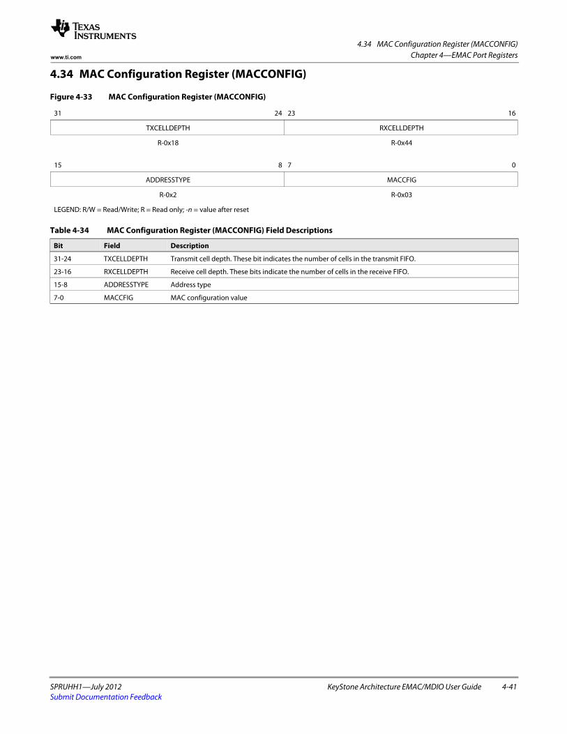
4.34 MAC Configuration Register (MACCONFIG)
SPRUHH1—July 2012 KeyStone Architecture EMAC/MDIO User Guide 4-41Submit Documentation Feedback
Chapter 4—EMAC Port Registerswww.ti.com
4.34 MAC Configuration Register (MACCONFIG)
Figure 4-33 MAC Configuration Register (MACCONFIG)
31 24 23 16
TXCELLDEPTH RXCELLDEPTH
R-0x18 R-0x44 spacer
15 8 7 0
ADDRESSTYPE MACCFIG
R-0x2 R-0x03
LEGEND: R/W = Read/Write; R = Read only; -n = value after reset
Table 4-34 MAC Configuration Register (MACCONFIG) Field Descriptions
Bit Field Description
31-24 TXCELLDEPTH Transmit cell depth. These bit indicates the number of cells in the transmit FIFO.
23-16 RXCELLDEPTH Receive cell depth. These bits indicate the number of cells in the receive FIFO.
15-8 ADDRESSTYPE Address type
7-0 MACCFIG MAC configuration value
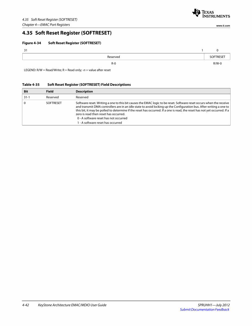
4.35 Soft Reset Register (SOFTRESET)
4-42 KeyStone Architecture EMAC/MDIO User Guide SPRUHH1—July 2012Submit Documentation Feedback
Chapter 4—EMAC Port Registers www.ti.com
4.35 Soft Reset Register (SOFTRESET)
Figure 4-34 Soft Reset Register (SOFTRESET)
31 1 0
Reserved SOFTRESET
R-0 R/W-0
LEGEND: R/W = Read/Write; R = Read only; -n = value after reset
Table 4-35 Soft Reset Register (SOFTRESET) Field Descriptions
Bit Field Description
31-1 Reserved Reserved
0 SOFTRESET Software reset. Writing a one to this bit causes the EMAC logic to be reset. Software reset occurs when the receive and transmit DMA controllers are in an idle state to avoid locking up the Configuration bus. After writing a one to this bit, it may be polled to determine if the reset has occurred. If a one is read, the reset has not yet occurred. If a zero is read then reset has occurred.
0 - A software reset has not occurred 1 - A software reset has occurred
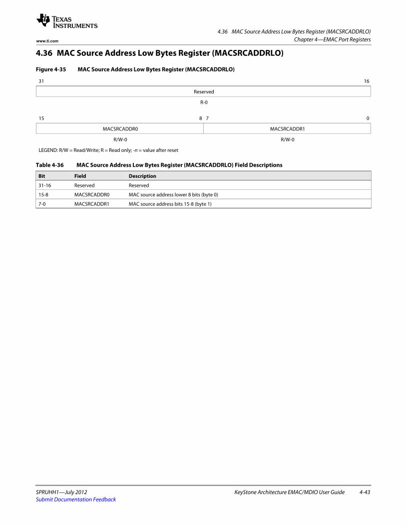
4.36 MAC Source Address Low Bytes Register (MACSRCADDRLO)
SPRUHH1—July 2012 KeyStone Architecture EMAC/MDIO User Guide 4-43Submit Documentation Feedback
Chapter 4—EMAC Port Registerswww.ti.com
4.36 MAC Source Address Low Bytes Register (MACSRCADDRLO)
Figure 4-35 MAC Source Address Low Bytes Register (MACSRCADDRLO)
31 16
Reserved
R-0spacer
15 8 7 0
MACSRCADDR0 MACSRCADDR1
R/W-0 R/W-0
LEGEND: R/W = Read/Write; R = Read only; -n = value after reset
Table 4-36 MAC Source Address Low Bytes Register (MACSRCADDRLO) Field Descriptions
Bit Field Description
31-16 Reserved Reserved
15-8 MACSRCADDR0 MAC source address lower 8 bits (byte 0)
7-0 MACSRCADDR1 MAC source address bits 15-8 (byte 1)
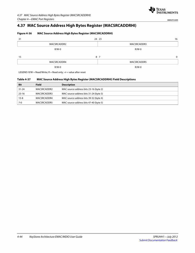
4.37 MAC Source Address High Bytes Register (MACSRCADDRHI)
4-44 KeyStone Architecture EMAC/MDIO User Guide SPRUHH1—July 2012Submit Documentation Feedback
Chapter 4—EMAC Port Registers www.ti.com
4.37 MAC Source Address High Bytes Register (MACSRCADDRHI)
Figure 4-36 MAC Source Address High Bytes Register (MACSRCADDRHI)
31 24 23 16
MACSRCADDR2 MACSRCADDR3
R/W-0 R/W-0 spacer
15 8 7 0
MACSRCADDR4 MACSRCADDR5
R/W-0 R/W-0
LEGEND: R/W = Read/Write; R = Read only; -n = value after reset
Table 4-37 MAC Source Address High Bytes Register (MACSRCADDRHI) Field Descriptions
Bit Field Description
31-24 MACSRCADDR2 MAC source address bits 23-16 (byte 2)
23-16 MACSRCADDR3 MAC source address bits 31-24 (byte 3)
15-8 MACSRCADDR4 MAC source address bits 39-32 (byte 4)
7-0 MACSRCADDR5 MAC source address bits 47-40 (byte 5)
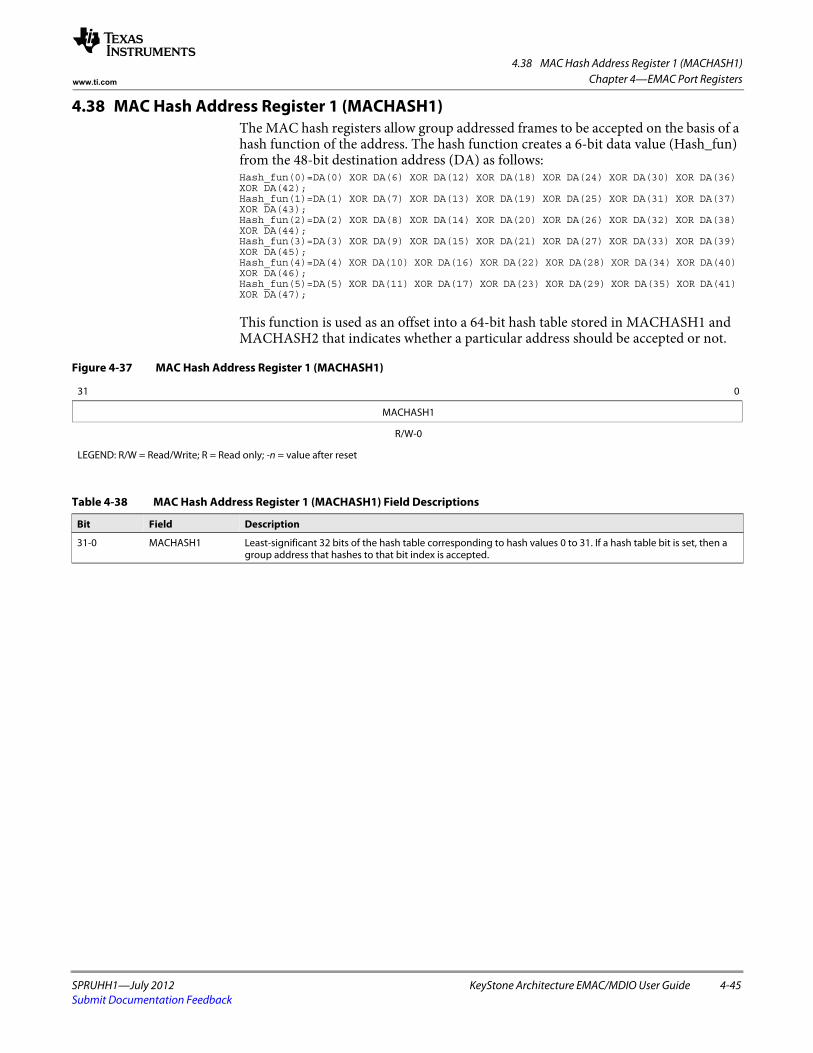
4.38 MAC Hash Address Register 1 (MACHASH1)
SPRUHH1—July 2012 KeyStone Architecture EMAC/MDIO User Guide 4-45Submit Documentation Feedback
Chapter 4—EMAC Port Registerswww.ti.com
4.38 MAC Hash Address Register 1 (MACHASH1)The MAC hash registers allow group addressed frames to be accepted on the basis of a hash function of the address. The hash function creates a 6-bit data value (Hash_fun) from the 48-bit destination address (DA) as follows: Hash_fun(0)=DA(0) XOR DA(6) XOR DA(12) XOR DA(18) XOR DA(24) XOR DA(30) XOR DA(36) XOR DA(42);Hash_fun(1)=DA(1) XOR DA(7) XOR DA(13) XOR DA(19) XOR DA(25) XOR DA(31) XOR DA(37) XOR DA(43);Hash_fun(2)=DA(2) XOR DA(8) XOR DA(14) XOR DA(20) XOR DA(26) XOR DA(32) XOR DA(38) XOR DA(44);Hash_fun(3)=DA(3) XOR DA(9) XOR DA(15) XOR DA(21) XOR DA(27) XOR DA(33) XOR DA(39) XOR DA(45);Hash_fun(4)=DA(4) XOR DA(10) XOR DA(16) XOR DA(22) XOR DA(28) XOR DA(34) XOR DA(40) XOR DA(46);Hash_fun(5)=DA(5) XOR DA(11) XOR DA(17) XOR DA(23) XOR DA(29) XOR DA(35) XOR DA(41) XOR DA(47);
This function is used as an offset into a 64-bit hash table stored in MACHASH1 and MACHASH2 that indicates whether a particular address should be accepted or not.
Figure 4-37 MAC Hash Address Register 1 (MACHASH1)
31 0
MACHASH1
R/W-0
LEGEND: R/W = Read/Write; R = Read only; -n = value after reset
Table 4-38 MAC Hash Address Register 1 (MACHASH1) Field Descriptions
Bit Field Description
31-0 MACHASH1 Least-significant 32 bits of the hash table corresponding to hash values 0 to 31. If a hash table bit is set, then a group address that hashes to that bit index is accepted.
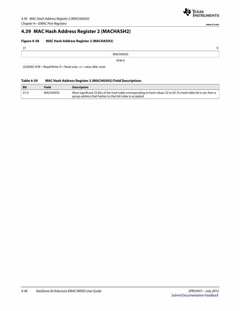
4.39 MAC Hash Address Register 2 (MACHASH2)
4-46 KeyStone Architecture EMAC/MDIO User Guide SPRUHH1—July 2012Submit Documentation Feedback
Chapter 4—EMAC Port Registers www.ti.com
4.39 MAC Hash Address Register 2 (MACHASH2)
Figure 4-38 MAC Hash Address Register 2 (MACHASH2)
31 0
MACHASH2
R/W-0
LEGEND: R/W = Read/Write; R = Read only; -n = value after reset
Table 4-39 MAC Hash Address Register 2 (MACHASH2) Field Descriptions
Bit Field Description
31-0 MACHASH2 Most-significant 32 bits of the hash table corresponding to hash values 32 to 63. If a hash table bit is set, then a group address that hashes to that bit index is accepted.
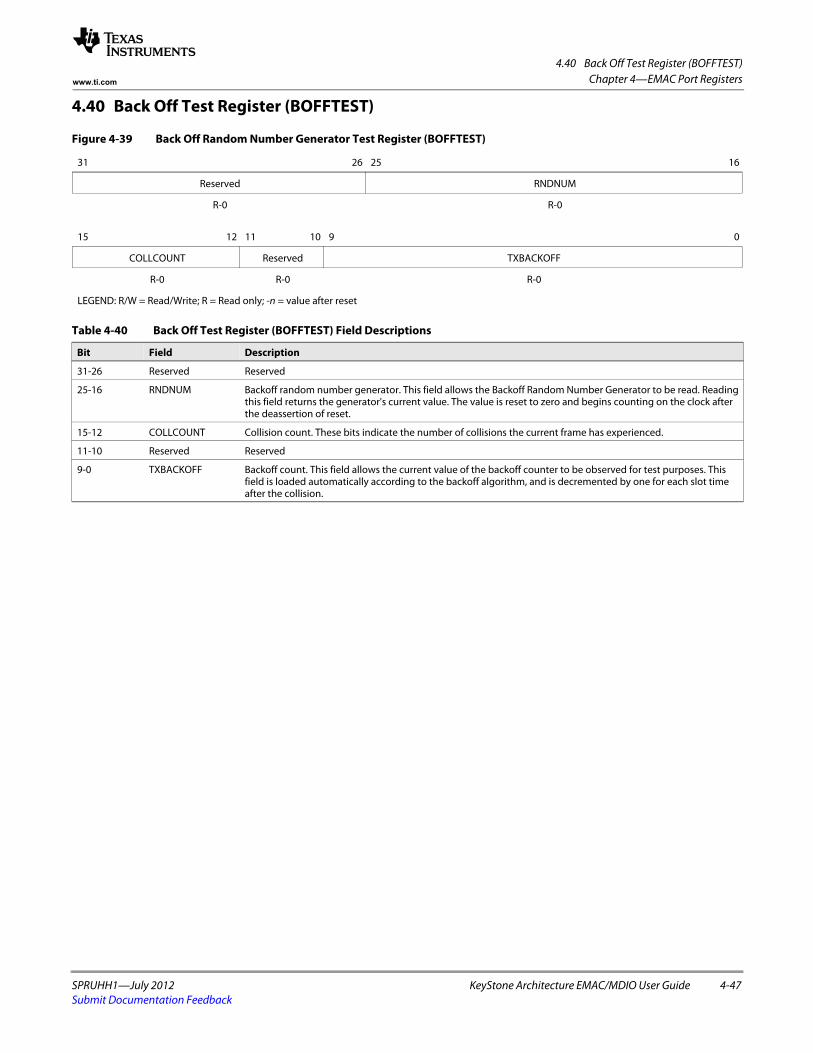
4.40 Back Off Test Register (BOFFTEST)
SPRUHH1—July 2012 KeyStone Architecture EMAC/MDIO User Guide 4-47Submit Documentation Feedback
Chapter 4—EMAC Port Registerswww.ti.com
4.40 Back Off Test Register (BOFFTEST)
Figure 4-39 Back Off Random Number Generator Test Register (BOFFTEST)
31 26 25 16
Reserved RNDNUM
R-0 R-0 spacer
15 12 11 10 9 0
COLLCOUNT Reserved TXBACKOFF
R-0 R-0 R-0
LEGEND: R/W = Read/Write; R = Read only; -n = value after reset
Table 4-40 Back Off Test Register (BOFFTEST) Field Descriptions
Bit Field Description
31-26 Reserved Reserved
25-16 RNDNUM Backoff random number generator. This field allows the Backoff Random Number Generator to be read. Reading this field returns the generator's current value. The value is reset to zero and begins counting on the clock after the deassertion of reset.
15-12 COLLCOUNT Collision count. These bits indicate the number of collisions the current frame has experienced.
11-10 Reserved Reserved
9-0 TXBACKOFF Backoff count. This field allows the current value of the backoff counter to be observed for test purposes. This field is loaded automatically according to the backoff algorithm, and is decremented by one for each slot time after the collision.
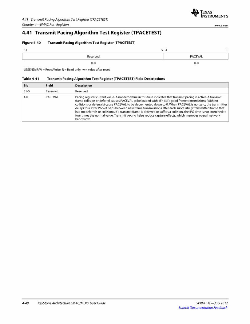
4.41 Transmit Pacing Algorithm Test Register (TPACETEST)
4-48 KeyStone Architecture EMAC/MDIO User Guide SPRUHH1—July 2012Submit Documentation Feedback
Chapter 4—EMAC Port Registers www.ti.com
4.41 Transmit Pacing Algorithm Test Register (TPACETEST)
Figure 4-40 Transmit Pacing Algorithm Test Register (TPACETEST)
31 5 4 0
Reserved PACEVAL
R-0 R-0
LEGEND: R/W = Read/Write; R = Read only; -n = value after reset
Table 4-41 Transmit Pacing Algorithm Test Register (TPACETEST) Field Descriptions
Bit Field Description
31-5 Reserved Reserved
4-0 PACEVAL Pacing register current value. A nonzero value in this field indicates that transmit pacing is active. A transmit frame collision or deferral causes PACEVAL to be loaded with 1Fh (31); good frame transmissions (with no collisions or deferrals) cause PACEVAL to be decremented down to 0. When PACEVAL is nonzero, the transmitter delays four Inter Packet Gaps between new frame transmissions after each successfully transmitted frame that had no deferrals or collisions. If a transmit frame is deferred or suffers a collision, the IPG time is not stretched to four times the normal value. Transmit pacing helps reduce capture effects, which improves overall network bandwidth.
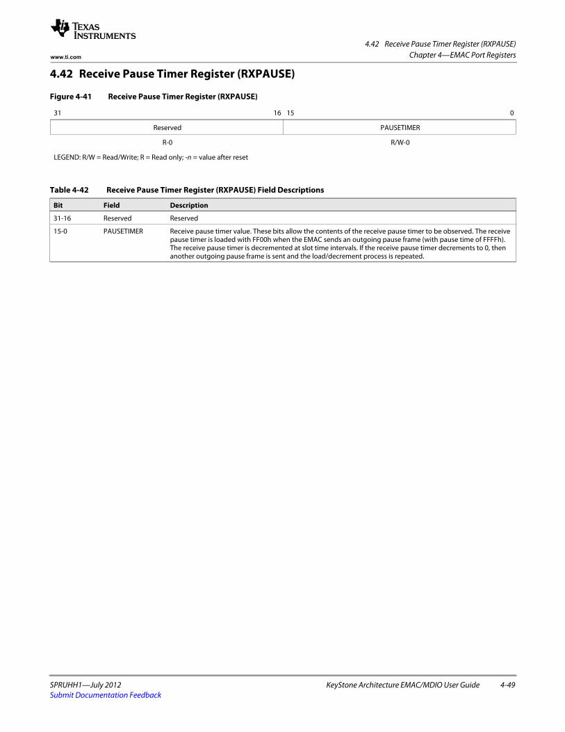
4.42 Receive Pause Timer Register (RXPAUSE)
SPRUHH1—July 2012 KeyStone Architecture EMAC/MDIO User Guide 4-49Submit Documentation Feedback
Chapter 4—EMAC Port Registerswww.ti.com
4.42 Receive Pause Timer Register (RXPAUSE)
Figure 4-41 Receive Pause Timer Register (RXPAUSE)
31 16 15 0
Reserved PAUSETIMER
R-0 R/W-0
LEGEND: R/W = Read/Write; R = Read only; -n = value after reset
Table 4-42 Receive Pause Timer Register (RXPAUSE) Field Descriptions
Bit Field Description
31-16 Reserved Reserved
15-0 PAUSETIMER Receive pause timer value. These bits allow the contents of the receive pause timer to be observed. The receive pause timer is loaded with FF00h when the EMAC sends an outgoing pause frame (with pause time of FFFFh). The receive pause timer is decremented at slot time intervals. If the receive pause timer decrements to 0, then another outgoing pause frame is sent and the load/decrement process is repeated.
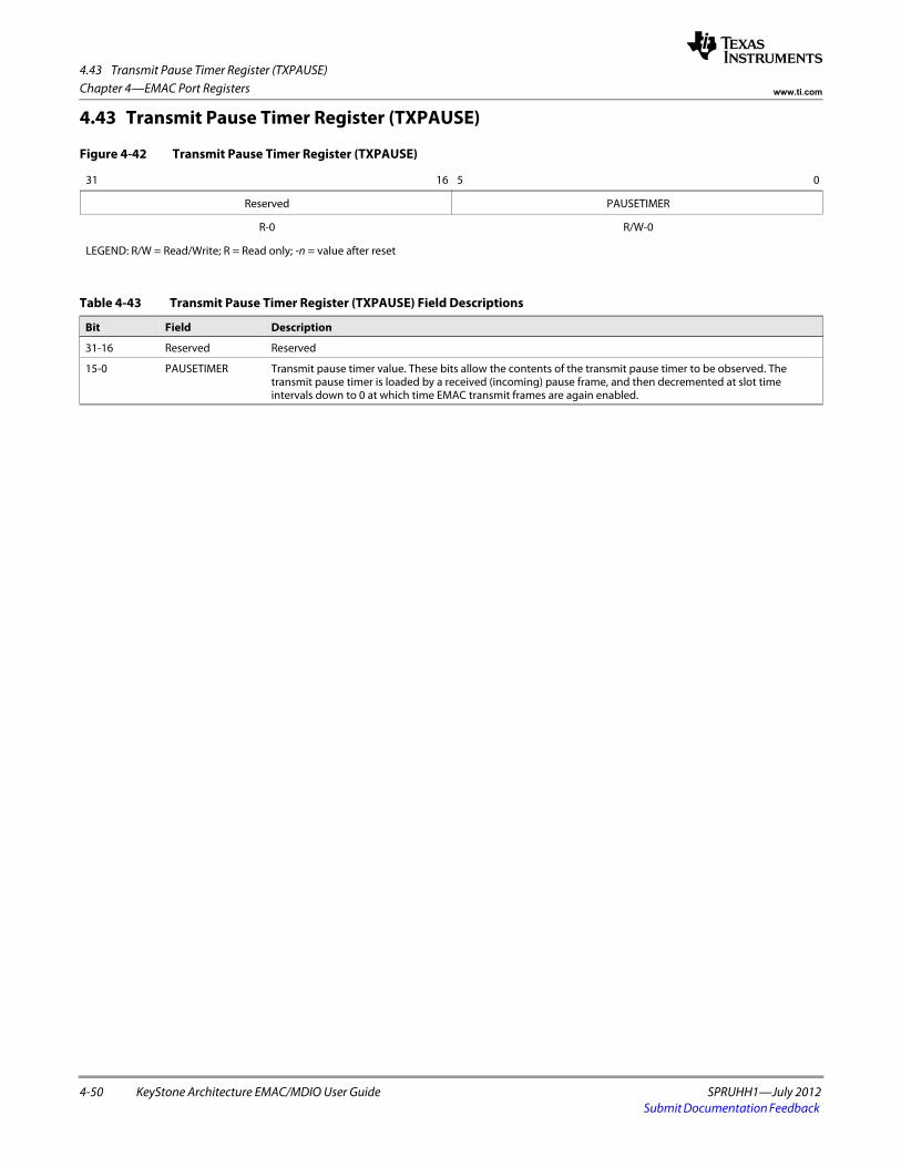
4.43 Transmit Pause Timer Register (TXPAUSE)
4-50 KeyStone Architecture EMAC/MDIO User Guide SPRUHH1—July 2012Submit Documentation Feedback
Chapter 4—EMAC Port Registers www.ti.com
4.43 Transmit Pause Timer Register (TXPAUSE)
Figure 4-42 Transmit Pause Timer Register (TXPAUSE)
31 16 5 0
Reserved PAUSETIMER
R-0 R/W-0
LEGEND: R/W = Read/Write; R = Read only; -n = value after reset
Table 4-43 Transmit Pause Timer Register (TXPAUSE) Field Descriptions
Bit Field Description
31-16 Reserved Reserved
15-0 PAUSETIMER Transmit pause timer value. These bits allow the contents of the transmit pause timer to be observed. The transmit pause timer is loaded by a received (incoming) pause frame, and then decremented at slot time intervals down to 0 at which time EMAC transmit frames are again enabled.
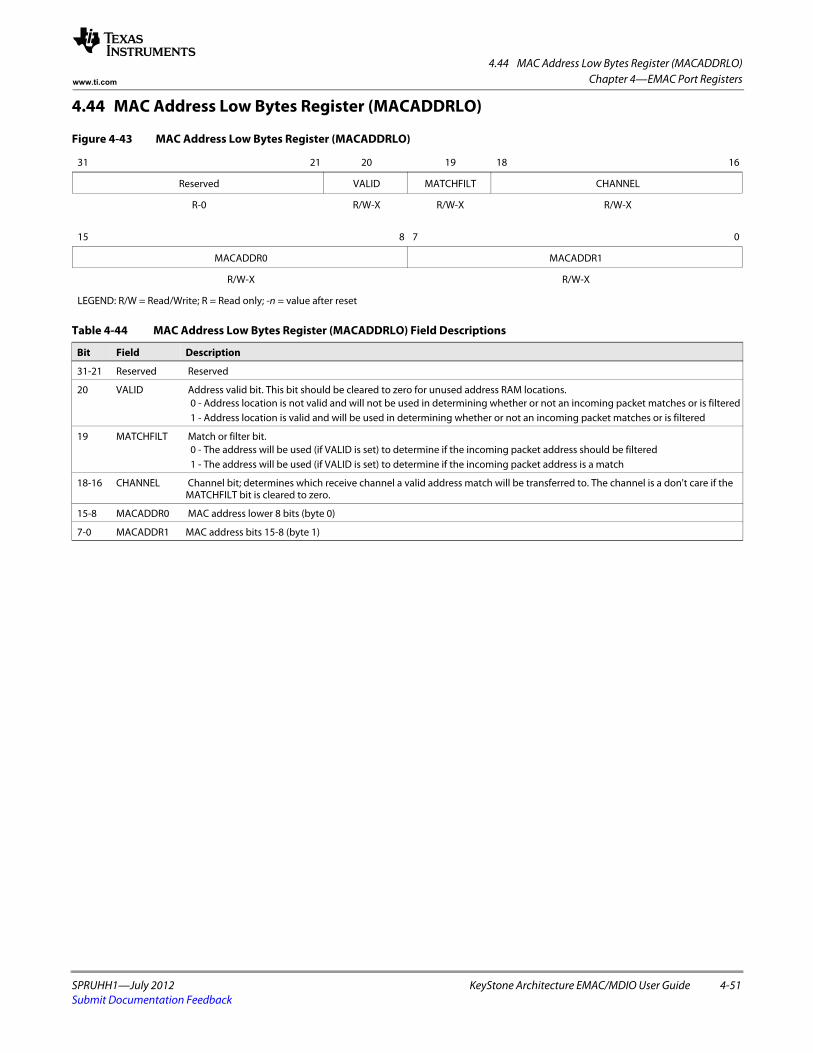
4.44 MAC Address Low Bytes Register (MACADDRLO)
SPRUHH1—July 2012 KeyStone Architecture EMAC/MDIO User Guide 4-51Submit Documentation Feedback
Chapter 4—EMAC Port Registerswww.ti.com
4.44 MAC Address Low Bytes Register (MACADDRLO)
Figure 4-43 MAC Address Low Bytes Register (MACADDRLO)
31 21 20 19 18 16
Reserved VALID MATCHFILT CHANNEL
R-0 R/W-X R/W-X R/W-Xspacer
15 8 7 0
MACADDR0 MACADDR1
R/W-X R/W-X
LEGEND: R/W = Read/Write; R = Read only; -n = value after reset
Table 4-44 MAC Address Low Bytes Register (MACADDRLO) Field Descriptions
Bit Field Description
31-21 Reserved Reserved
20 VALID Address valid bit. This bit should be cleared to zero for unused address RAM locations.0 - Address location is not valid and will not be used in determining whether or not an incoming packet matches or is filtered1 - Address location is valid and will be used in determining whether or not an incoming packet matches or is filtered
19 MATCHFILT Match or filter bit.0 - The address will be used (if VALID is set) to determine if the incoming packet address should be filtered1 - The address will be used (if VALID is set) to determine if the incoming packet address is a match
18-16 CHANNEL Channel bit; determines which receive channel a valid address match will be transferred to. The channel is a don't care if the MATCHFILT bit is cleared to zero.
15-8 MACADDR0 MAC address lower 8 bits (byte 0)
7-0 MACADDR1 MAC address bits 15-8 (byte 1)
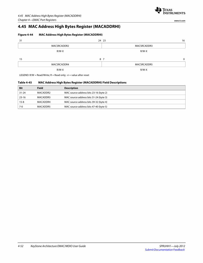
4.45 MAC Address High Bytes Register (MACADDRHI)
4-52 KeyStone Architecture EMAC/MDIO User Guide SPRUHH1—July 2012Submit Documentation Feedback
Chapter 4—EMAC Port Registers www.ti.com
4.45 MAC Address High Bytes Register (MACADDRHI)
Figure 4-44 MAC Address High Bytes Register (MACADDRHI)
31 24 23 16
MACSRCADDR2 MACSRCADDR3
R/W-X R/W-Xspacer
15 8 7 0
MACSRCADDR4 MACSRCADDR5
R/W-X R/W-X
LEGEND: R/W = Read/Write; R = Read only; -n = value after reset
Table 4-45 MAC Address High Bytes Register (MACADDRHI) Field Descriptions
Bit Field Description
31-24 MACADDR2 MAC source address bits 23-16 (byte 2)
23-16 MACADDR3 MAC source address bits 31-24 (byte 3)
15-8 MACADDR4 MAC source address bits 39-32 (byte 4)
7-0 MACADDR5 MAC source address bits 47-40 (byte 5)
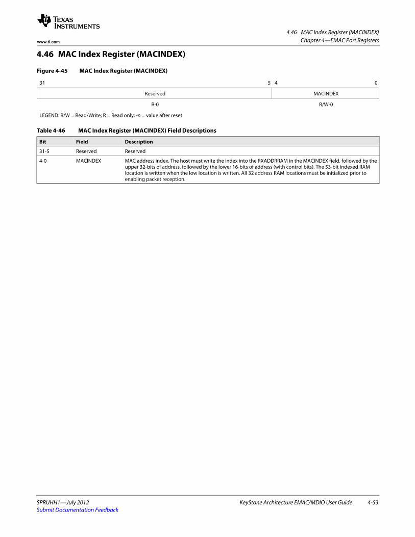
4.46 MAC Index Register (MACINDEX)
SPRUHH1—July 2012 KeyStone Architecture EMAC/MDIO User Guide 4-53Submit Documentation Feedback
Chapter 4—EMAC Port Registerswww.ti.com
4.46 MAC Index Register (MACINDEX)
Figure 4-45 MAC Index Register (MACINDEX)
31 5 4 0
Reserved MACINDEX
R-0 R/W-0
LEGEND: R/W = Read/Write; R = Read only; -n = value after reset
Table 4-46 MAC Index Register (MACINDEX) Field Descriptions
Bit Field Description
31-5 Reserved Reserved
4-0 MACINDEX MAC address index. The host must write the index into the RXADDRRAM in the MACINDEX field, followed by the upper 32-bits of address, followed by the lower 16-bits of address (with control bits). The 53-bit indexed RAM location is written when the low location is written. All 32 address RAM locations must be initialized prior to enabling packet reception.
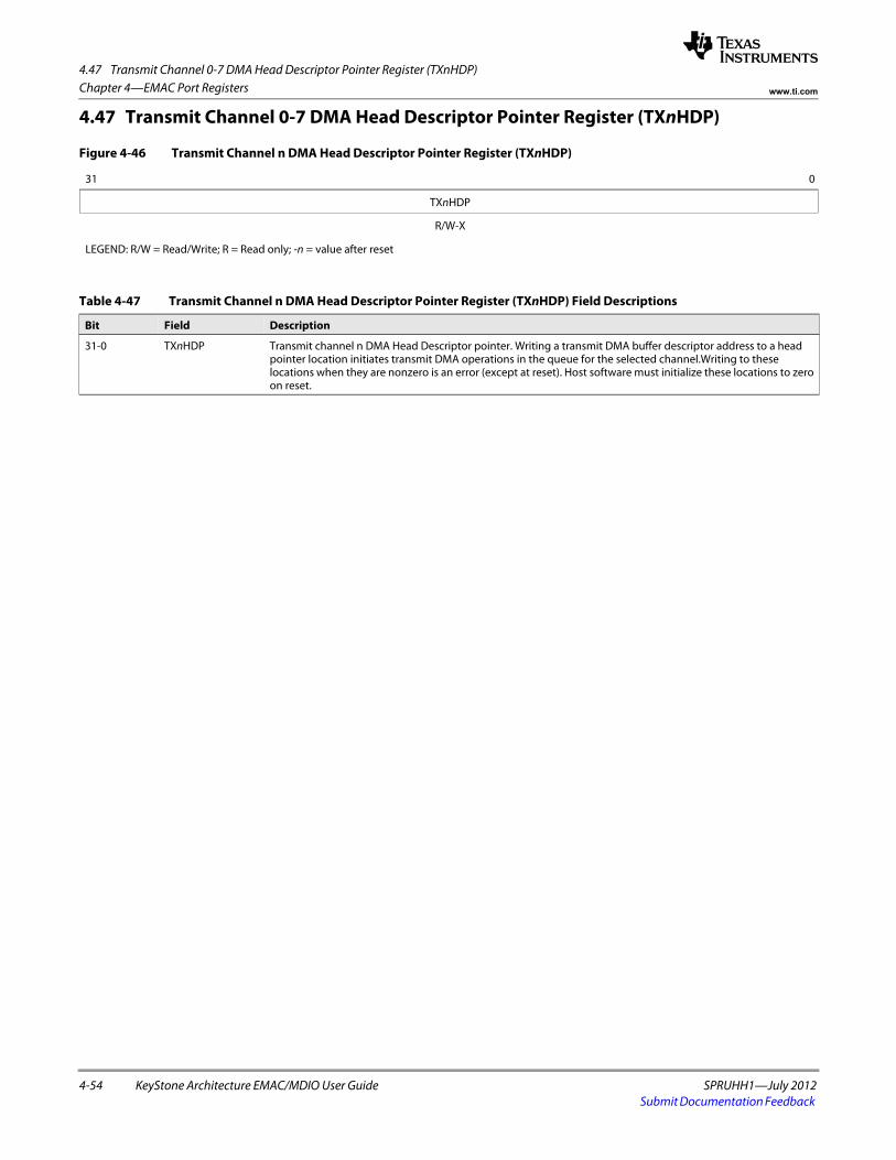
4.47 Transmit Channel 0-7 DMA Head Descriptor Pointer Register (TXnHDP)
4-54 KeyStone Architecture EMAC/MDIO User Guide SPRUHH1—July 2012Submit Documentation Feedback
Chapter 4—EMAC Port Registers www.ti.com
4.47 Transmit Channel 0-7 DMA Head Descriptor Pointer Register (TXnHDP)
Figure 4-46 Transmit Channel n DMA Head Descriptor Pointer Register (TXnHDP)
31 0
TXnHDP
R/W-X
LEGEND: R/W = Read/Write; R = Read only; -n = value after reset
Table 4-47 Transmit Channel n DMA Head Descriptor Pointer Register (TXnHDP) Field Descriptions
Bit Field Description
31-0 TXnHDP Transmit channel n DMA Head Descriptor pointer. Writing a transmit DMA buffer descriptor address to a head pointer location initiates transmit DMA operations in the queue for the selected channel.Writing to these locations when they are nonzero is an error (except at reset). Host software must initialize these locations to zero on reset.
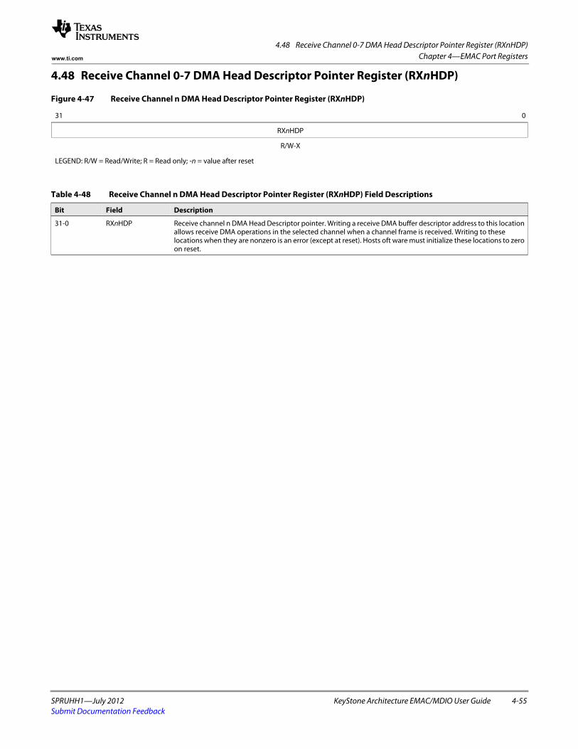
4.48 Receive Channel 0-7 DMA Head Descriptor Pointer Register (RXnHDP)
SPRUHH1—July 2012 KeyStone Architecture EMAC/MDIO User Guide 4-55Submit Documentation Feedback
Chapter 4—EMAC Port Registerswww.ti.com
4.48 Receive Channel 0-7 DMA Head Descriptor Pointer Register (RXnHDP)
Figure 4-47 Receive Channel n DMA Head Descriptor Pointer Register (RXnHDP)
31 0
RXnHDP
R/W-X
LEGEND: R/W = Read/Write; R = Read only; -n = value after reset
Table 4-48 Receive Channel n DMA Head Descriptor Pointer Register (RXnHDP) Field Descriptions
Bit Field Description
31-0 RXnHDP Receive channel n DMA Head Descriptor pointer. Writing a receive DMA buffer descriptor address to this location allows receive DMA operations in the selected channel when a channel frame is received. Writing to these locations when they are nonzero is an error (except at reset). Hosts oft ware must initialize these locations to zero on reset.
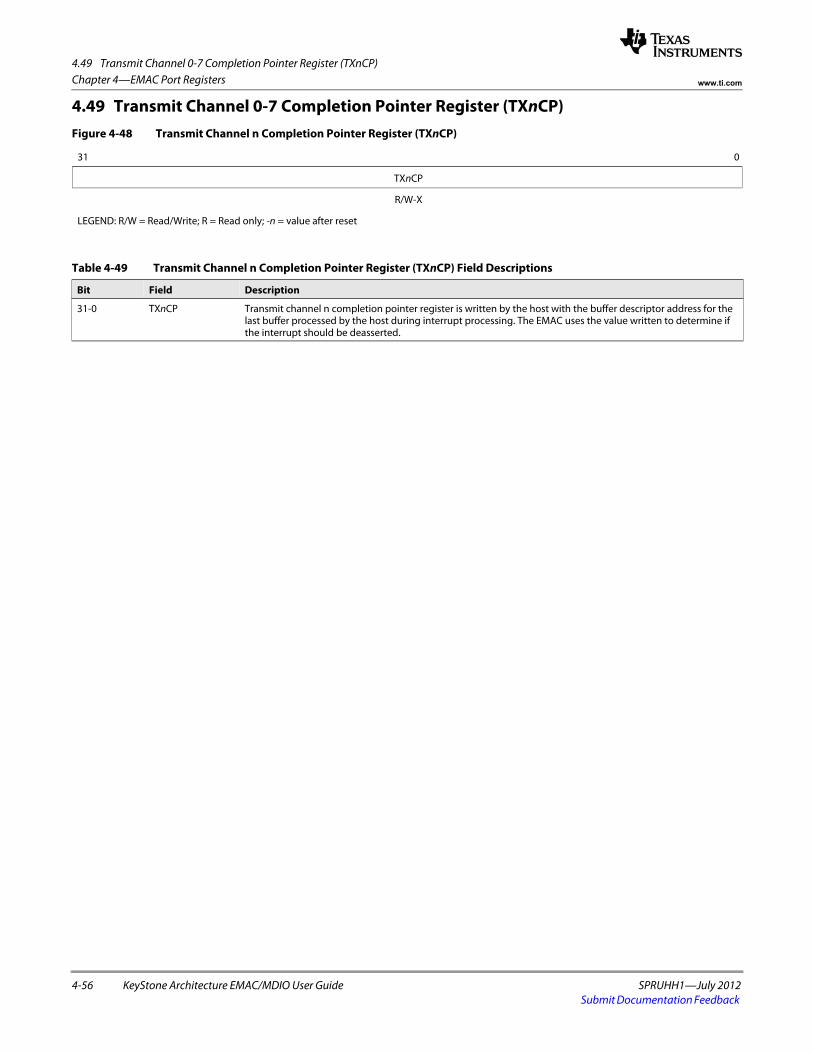
4.49 Transmit Channel 0-7 Completion Pointer Register (TXnCP)
4-56 KeyStone Architecture EMAC/MDIO User Guide SPRUHH1—July 2012Submit Documentation Feedback
Chapter 4—EMAC Port Registers www.ti.com
4.49 Transmit Channel 0-7 Completion Pointer Register (TXnCP)Figure 4-48 Transmit Channel n Completion Pointer Register (TXnCP)
31 0
TXnCP
R/W-X
LEGEND: R/W = Read/Write; R = Read only; -n = value after reset
Table 4-49 Transmit Channel n Completion Pointer Register (TXnCP) Field Descriptions
Bit Field Description
31-0 TXnCP Transmit channel n completion pointer register is written by the host with the buffer descriptor address for the last buffer processed by the host during interrupt processing. The EMAC uses the value written to determine if the interrupt should be deasserted.
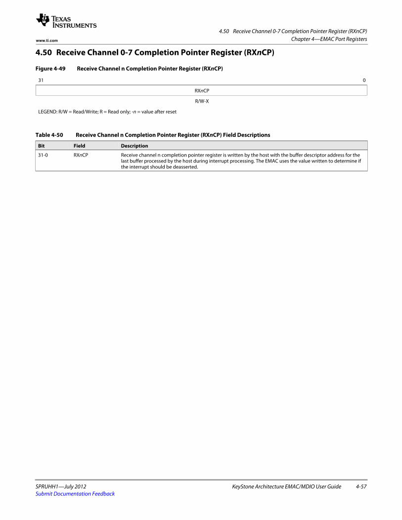
4.50 Receive Channel 0-7 Completion Pointer Register (RXnCP)
SPRUHH1—July 2012 KeyStone Architecture EMAC/MDIO User Guide 4-57Submit Documentation Feedback
Chapter 4—EMAC Port Registerswww.ti.com
4.50 Receive Channel 0-7 Completion Pointer Register (RXnCP)
Figure 4-49 Receive Channel n Completion Pointer Register (RXnCP)
31 0
RXnCP
R/W-X
LEGEND: R/W = Read/Write; R = Read only; -n = value after reset
Table 4-50 Receive Channel n Completion Pointer Register (RXnCP) Field Descriptions
Bit Field Description
31-0 RXnCP Receive channel n completion pointer register is written by the host with the buffer descriptor address for the last buffer processed by the host during interrupt processing. The EMAC uses the value written to determine if the interrupt should be deasserted.

4.50 Receive Channel 0-7 Completion Pointer Register (RXnCP)
4-58 KeyStone Architecture EMAC/MDIO User Guide SPRUHH1—July 2012Submit Documentation Feedback
Chapter 4—EMAC Port Registers www.ti.com
SPRUHH1—July 2012 KeyStone Architecture EMAC/MDIO User Guide 5-1Submit Documentation Feedback
Chapter 5
MDIO Registers
5.1 "Introduction" on page 5-2 5.2 "MDIO Version Register (VERSION)" on page 5-3 5.3 "MDIO Control Register (CONTROL)" on page 5-4 5.4 "PHY Acknowledge Status Register (ALIVE)" on page 5-5 5.5 "PHY Link Status Register (LINK)" on page 5-6 5.6 "MDIO Link Status Change Interrupt (Unmasked) Register (LINKINTRAW)" on
page 5-7 5.7 "MDIO Link Status Change Interrupt (Masked) Register (LINKINTMASKED)" on
page 5-8 5.8 "MDIO User Command Complete Interrupt (Unmasked) Register (USERINTRAW)"
on page 5-9 5.9 "MDIO User Command Complete Interrupt (Masked) Register (USERINTMASKED)"
on page 5-10 5.10 "MDIO User Command Complete Interrupt Mask Set Register Descriptions
(USERINTMASKSET)" on page 5-11 5.11 "MDIO User Command Complete Interrupt Mask Clear Register
(USERINTMASKCLEAR)" on page 5-12 5.12 "MDIO User Access Register 0 (USERACCESS0)" on page 5-13 5.13 "MDIO User PHY Select Register 0 (USERPHYSEL0)" on page 5-14 5.14 "MDIO User Access Register 1 (USERACCESS1)" on page 5-15 5.15 "MDIO User PHY Select Register 1 (USERPHYSEL1)" on page 5-16
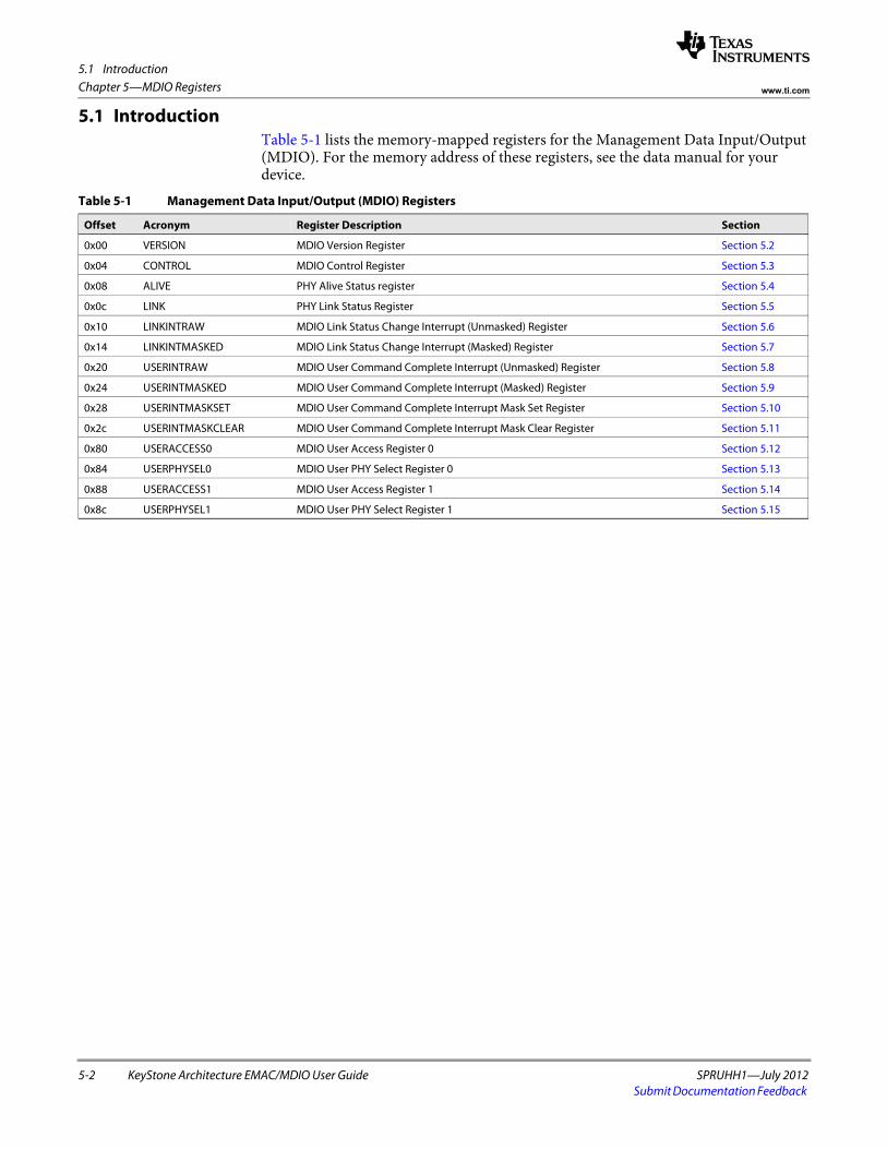
5.1 Introduction
5-2 KeyStone Architecture EMAC/MDIO User Guide SPRUHH1—July 2012Submit Documentation Feedback
Chapter 5—MDIO Registers www.ti.com
5.1 IntroductionTable 5-1 lists the memory-mapped registers for the Management Data Input/Output (MDIO). For the memory address of these registers, see the data manual for your device.
Table 5-1 Management Data Input/Output (MDIO) Registers
Offset Acronym Register Description Section
0x00 VERSION MDIO Version Register Section 5.2
0x04 CONTROL MDIO Control Register Section 5.3
0x08 ALIVE PHY Alive Status register Section 5.4
0x0c LINK PHY Link Status Register Section 5.5
0x10 LINKINTRAW MDIO Link Status Change Interrupt (Unmasked) Register Section 5.6
0x14 LINKINTMASKED MDIO Link Status Change Interrupt (Masked) Register Section 5.7
0x20 USERINTRAW MDIO User Command Complete Interrupt (Unmasked) Register Section 5.8
0x24 USERINTMASKED MDIO User Command Complete Interrupt (Masked) Register Section 5.9
0x28 USERINTMASKSET MDIO User Command Complete Interrupt Mask Set Register Section 5.10
0x2c USERINTMASKCLEAR MDIO User Command Complete Interrupt Mask Clear Register Section 5.11
0x80 USERACCESS0 MDIO User Access Register 0 Section 5.12
0x84 USERPHYSEL0 MDIO User PHY Select Register 0 Section 5.13
0x88 USERACCESS1 MDIO User Access Register 1 Section 5.14
0x8c USERPHYSEL1 MDIO User PHY Select Register 1 Section 5.15
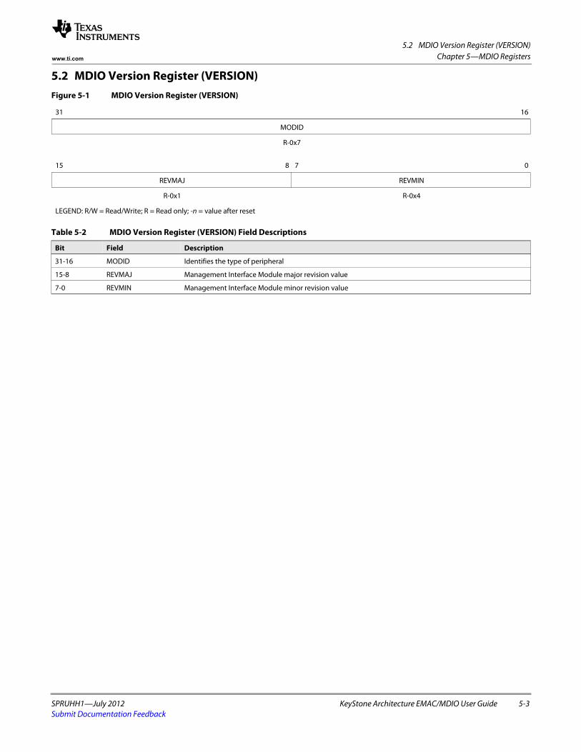
5.2 MDIO Version Register (VERSION)
SPRUHH1—July 2012 KeyStone Architecture EMAC/MDIO User Guide 5-3Submit Documentation Feedback
Chapter 5—MDIO Registerswww.ti.com
5.2 MDIO Version Register (VERSION)Figure 5-1 MDIO Version Register (VERSION)
31 16
MODID
R-0x7 spacer
15 8 7 0
REVMAJ REVMIN
R-0x1 R-0x4
LEGEND: R/W = Read/Write; R = Read only; -n = value after reset
Table 5-2 MDIO Version Register (VERSION) Field Descriptions
Bit Field Description
31-16 MODID Identifies the type of peripheral
15-8 REVMAJ Management Interface Module major revision value
7-0 REVMIN Management Interface Module minor revision value
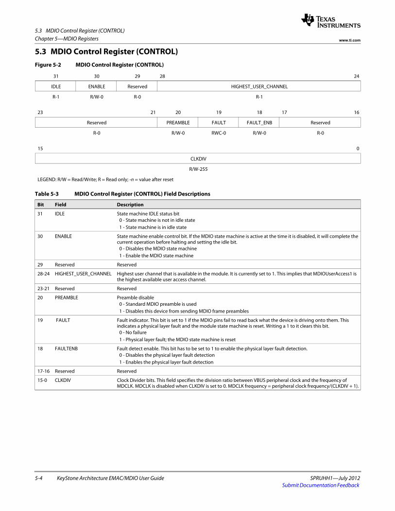
5.3 MDIO Control Register (CONTROL)
5-4 KeyStone Architecture EMAC/MDIO User Guide SPRUHH1—July 2012Submit Documentation Feedback
Chapter 5—MDIO Registers www.ti.com
5.3 MDIO Control Register (CONTROL)Figure 5-2 MDIO Control Register (CONTROL)
31 30 29 28 24
IDLE ENABLE Reserved HIGHEST_USER_CHANNEL
R-1 R/W-0 R-0 R-1
23 21 20 19 18 17 16
Reserved PREAMBLE FAULT FAULT_ENB Reserved
R-0 R/W-0 RWC-0 R/W-0 R-0
15 0
CLKDIV
R/W-255
LEGEND: R/W = Read/Write; R = Read only; -n = value after reset
Table 5-3 MDIO Control Register (CONTROL) Field Descriptions
Bit Field Description
31 IDLE State machine IDLE status bit0 - State machine is not in idle state1 - State machine is in idle state
30 ENABLE State machine enable control bit. If the MDIO state machine is active at the time it is disabled, it will complete the current operation before halting and setting the idle bit.
0 - Disables the MDIO state machine1 - Enable the MDIO state machine
29 Reserved Reserved
28-24 HIGHEST_USER_CHANNEL Highest user channel that is available in the module. It is currently set to 1. This implies that MDIOUserAccess1 is the highest available user access channel.
23-21 Reserved Reserved
20 PREAMBLE Preamble disable0 - Standard MDIO preamble is used1 - Disables this device from sending MDIO frame preambles
19 FAULT Fault indicator. This bit is set to 1 if the MDIO pins fail to read back what the device is driving onto them. This indicates a physical layer fault and the module state machine is reset. Writing a 1 to it clears this bit.
0 - No failure1 - Physical layer fault; the MDIO state machine is reset
18 FAULTENB Fault detect enable. This bit has to be set to 1 to enable the physical layer fault detection.0 - Disables the physical layer fault detection1 - Enables the physical layer fault detection
17-16 Reserved Reserved
15-0 CLKDIV Clock Divider bits. This field specifies the division ratio between VBUS peripheral clock and the frequency of MDCLK. MDCLK is disabled when CLKDIV is set to 0. MDCLK frequency = peripheral clock frequency/(CLKDIV + 1).
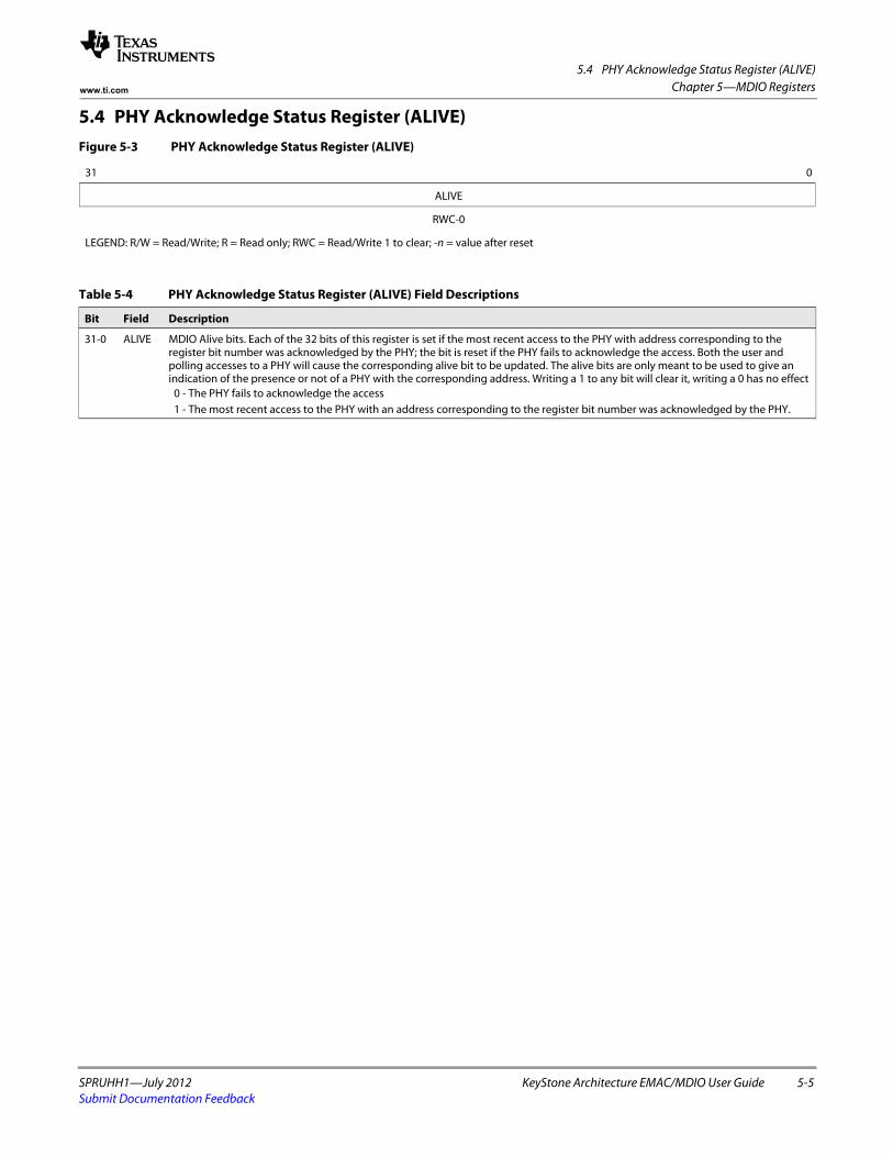
5.4 PHY Acknowledge Status Register (ALIVE)
SPRUHH1—July 2012 KeyStone Architecture EMAC/MDIO User Guide 5-5Submit Documentation Feedback
Chapter 5—MDIO Registerswww.ti.com
5.4 PHY Acknowledge Status Register (ALIVE)Figure 5-3 PHY Acknowledge Status Register (ALIVE)
31 0
ALIVE
RWC-0
LEGEND: R/W = Read/Write; R = Read only; RWC = Read/Write 1 to clear; -n = value after reset
Table 5-4 PHY Acknowledge Status Register (ALIVE) Field Descriptions
Bit Field Description
31-0 ALIVE MDIO Alive bits. Each of the 32 bits of this register is set if the most recent access to the PHY with address corresponding to the register bit number was acknowledged by the PHY; the bit is reset if the PHY fails to acknowledge the access. Both the user and polling accesses to a PHY will cause the corresponding alive bit to be updated. The alive bits are only meant to be used to give an indication of the presence or not of a PHY with the corresponding address. Writing a 1 to any bit will clear it, writing a 0 has no effect
0 - The PHY fails to acknowledge the access 1 - The most recent access to the PHY with an address corresponding to the register bit number was acknowledged by the PHY.
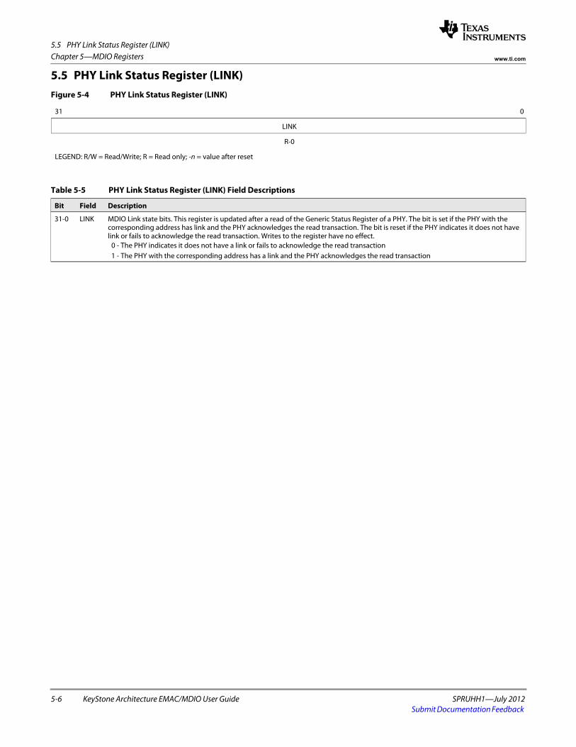
5.5 PHY Link Status Register (LINK)
5-6 KeyStone Architecture EMAC/MDIO User Guide SPRUHH1—July 2012Submit Documentation Feedback
Chapter 5—MDIO Registers www.ti.com
5.5 PHY Link Status Register (LINK)Figure 5-4 PHY Link Status Register (LINK)
31 0
LINK
R-0
LEGEND: R/W = Read/Write; R = Read only; -n = value after reset
Table 5-5 PHY Link Status Register (LINK) Field Descriptions
Bit Field Description
31-0 LINK MDIO Link state bits. This register is updated after a read of the Generic Status Register of a PHY. The bit is set if the PHY with the corresponding address has link and the PHY acknowledges the read transaction. The bit is reset if the PHY indicates it does not have link or fails to acknowledge the read transaction. Writes to the register have no effect.
0 - The PHY indicates it does not have a link or fails to acknowledge the read transaction 1 - The PHY with the corresponding address has a link and the PHY acknowledges the read transaction
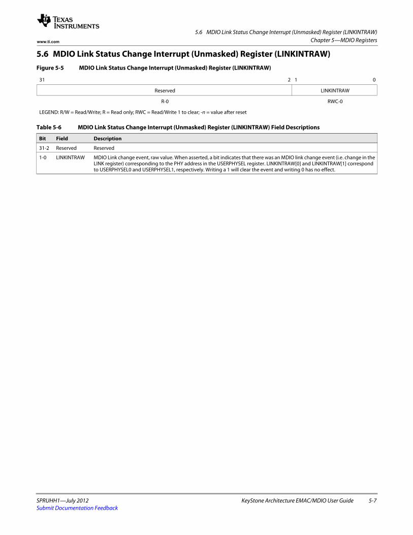
5.6 MDIO Link Status Change Interrupt (Unmasked) Register (LINKINTRAW)
SPRUHH1—July 2012 KeyStone Architecture EMAC/MDIO User Guide 5-7Submit Documentation Feedback
Chapter 5—MDIO Registerswww.ti.com
5.6 MDIO Link Status Change Interrupt (Unmasked) Register (LINKINTRAW)Figure 5-5 MDIO Link Status Change Interrupt (Unmasked) Register (LINKINTRAW)
31 2 1 0
Reserved LINKINTRAW
R-0 RWC-0
LEGEND: R/W = Read/Write; R = Read only; RWC = Read/Write 1 to clear; -n = value after reset
Table 5-6 MDIO Link Status Change Interrupt (Unmasked) Register (LINKINTRAW) Field Descriptions
Bit Field Description
31-2 Reserved Reserved
1-0 LINKINTRAW MDIO Link change event, raw value. When asserted, a bit indicates that there was an MDIO link change event (i.e. change in the LINK register) corresponding to the PHY address in the USERPHYSEL register. LINKINTRAW[0] and LINKINTRAW[1] correspond to USERPHYSEL0 and USERPHYSEL1, respectively. Writing a 1 will clear the event and writing 0 has no effect.
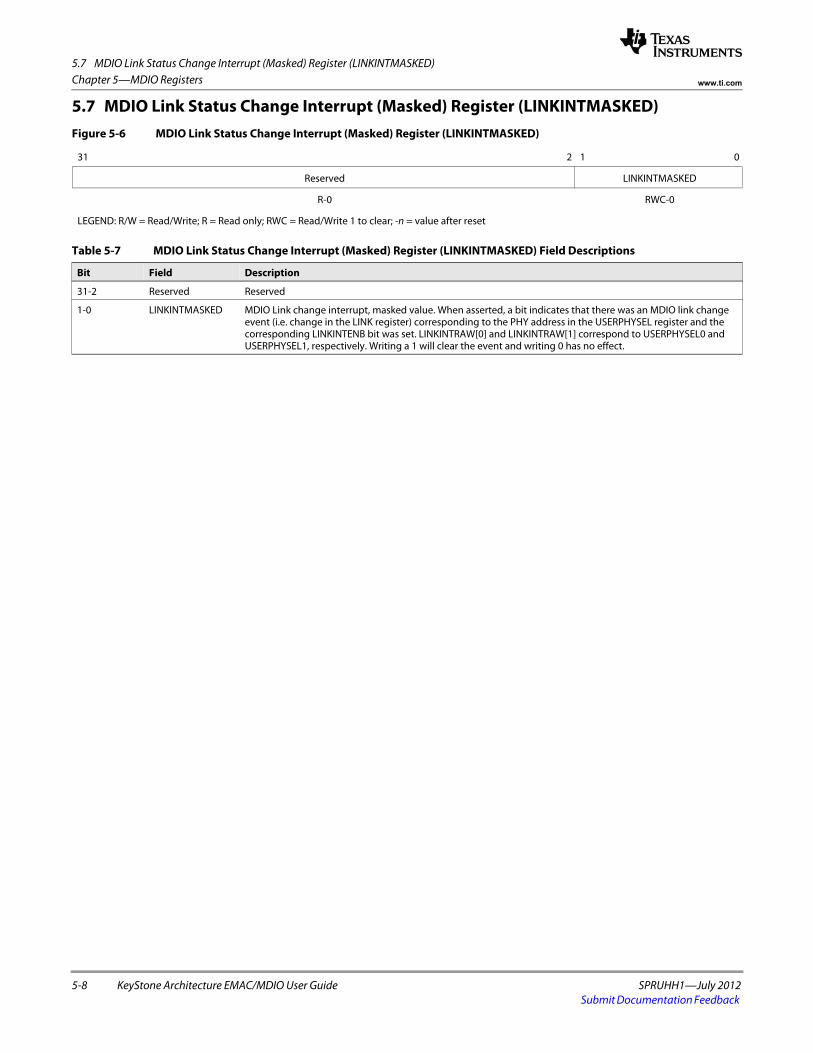
5.7 MDIO Link Status Change Interrupt (Masked) Register (LINKINTMASKED)
5-8 KeyStone Architecture EMAC/MDIO User Guide SPRUHH1—July 2012Submit Documentation Feedback
Chapter 5—MDIO Registers www.ti.com
5.7 MDIO Link Status Change Interrupt (Masked) Register (LINKINTMASKED)Figure 5-6 MDIO Link Status Change Interrupt (Masked) Register (LINKINTMASKED)
31 2 1 0
Reserved LINKINTMASKED
R-0 RWC-0
LEGEND: R/W = Read/Write; R = Read only; RWC = Read/Write 1 to clear; -n = value after reset
Table 5-7 MDIO Link Status Change Interrupt (Masked) Register (LINKINTMASKED) Field Descriptions
Bit Field Description
31-2 Reserved Reserved
1-0 LINKINTMASKED MDIO Link change interrupt, masked value. When asserted, a bit indicates that there was an MDIO link change event (i.e. change in the LINK register) corresponding to the PHY address in the USERPHYSEL register and the corresponding LINKINTENB bit was set. LINKINTRAW[0] and LINKINTRAW[1] correspond to USERPHYSEL0 and USERPHYSEL1, respectively. Writing a 1 will clear the event and writing 0 has no effect.
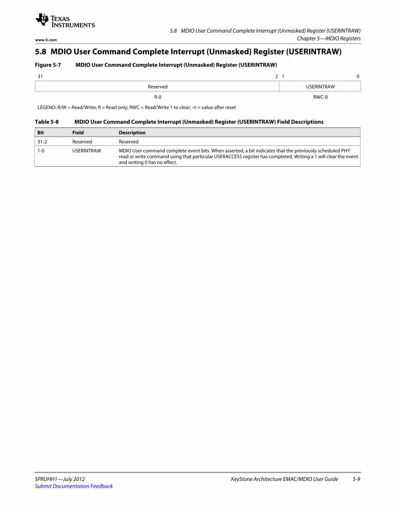
5.8 MDIO User Command Complete Interrupt (Unmasked) Register (USERINTRAW)
SPRUHH1—July 2012 KeyStone Architecture EMAC/MDIO User Guide 5-9Submit Documentation Feedback
Chapter 5—MDIO Registerswww.ti.com
5.8 MDIO User Command Complete Interrupt (Unmasked) Register (USERINTRAW)Figure 5-7 MDIO User Command Complete Interrupt (Unmasked) Register (USERINTRAW)
31 2 1 0
Reserved USERINTRAW
R-0 RWC-0
LEGEND: R/W = Read/Write; R = Read only; RWC = Read/Write 1 to clear; -n = value after reset
Table 5-8 MDIO User Command Complete Interrupt (Unmasked) Register (USERINTRAW) Field Descriptions
Bit Field Description
31-2 Reserved Reserved
1-0 USERINTRAW MDIO User command complete event bits. When asserted, a bit indicates that the previously scheduled PHY read or write command using that particular USERACCESS register has completed. Writing a 1 will clear the event and writing 0 has no effect.
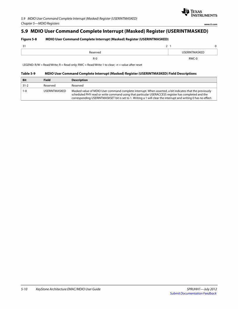
5.9 MDIO User Command Complete Interrupt (Masked) Register (USERINTMASKED)
5-10 KeyStone Architecture EMAC/MDIO User Guide SPRUHH1—July 2012Submit Documentation Feedback
Chapter 5—MDIO Registers www.ti.com
5.9 MDIO User Command Complete Interrupt (Masked) Register (USERINTMASKED)Figure 5-8 MDIO User Command Complete Interrupt (Masked) Register (USERINTMASKED)
31 2 1 0
Reserved USERINTMASKED
R-0 RWC-0
LEGEND: R/W = Read/Write; R = Read only; RWC = Read/Write 1 to clear; -n = value after reset
Table 5-9 MDIO User Command Complete Interrupt (Masked) Register (USERINTMASKED) Field Descriptions
Bit Field Description
31-2 Reserved Reserved
1-0 USERINTMASKED Masked value of MDIO User command complete interrupt. When asserted, a bit indicates that the previously scheduled PHY read or write command using that particular USERACCESS register has completed and the corresponding USERINTMASKSET bit is set to 1. Writing a 1 will clear the interrupt and writing 0 has no effect.
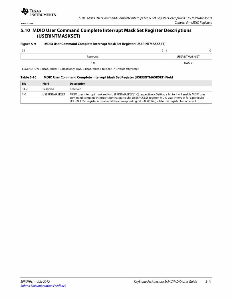
5.10 MDIO User Command Complete Interrupt Mask Set Register Descriptions (USERINTMASKSET)
SPRUHH1—July 2012 KeyStone Architecture EMAC/MDIO User Guide 5-11Submit Documentation Feedback
Chapter 5—MDIO Registerswww.ti.com
5.10 MDIO User Command Complete Interrupt Mask Set Register Descriptions (USERINTMASKSET)
Figure 5-9 MDIO User Command Complete Interrupt Mask Set Register (USERINTMASKSET)
31 2 1 0
Reserved USERINTMASKSET
R-0 RWC-0
LEGEND: R/W = Read/Write; R = Read only; RWC = Read/Write 1 to clear; -n = value after reset
Table 5-10 MDIO User Command Complete Interrupt Mask Set Register (USERINTMASKSET) Field
Bit Field Description
31-2 Reserved Reserved
1-0 USERINTMASKSET MDIO user interrupt mask set for USERINTMASKED[1-0] respectively. Setting a bit to 1 will enable MDIO user command complete interrupts for that particular USERACCESS register. MDIO user interrupt for a particular USERACCESS register is disabled if the corresponding bit is 0. Writing a 0 to this register has no effect.
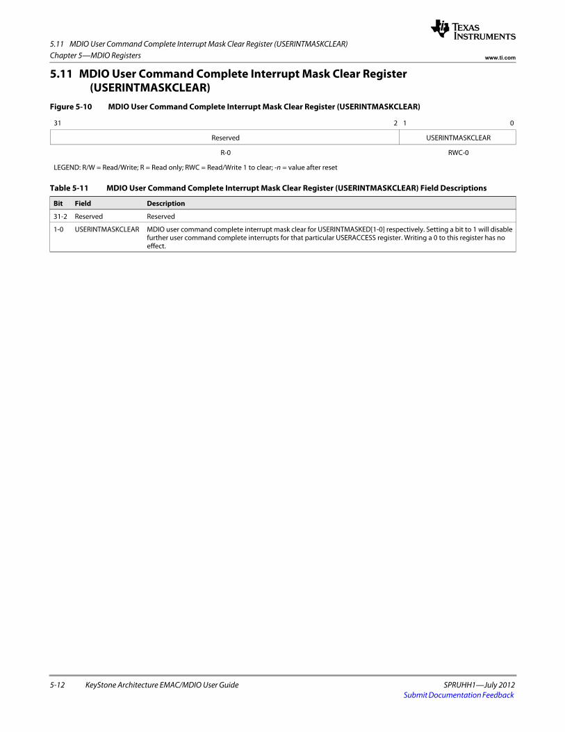
5.11 MDIO User Command Complete Interrupt Mask Clear Register (USERINTMASKCLEAR)
5-12 KeyStone Architecture EMAC/MDIO User Guide SPRUHH1—July 2012Submit Documentation Feedback
Chapter 5—MDIO Registers www.ti.com
5.11 MDIO User Command Complete Interrupt Mask Clear Register (USERINTMASKCLEAR)
Figure 5-10 MDIO User Command Complete Interrupt Mask Clear Register (USERINTMASKCLEAR)
31 2 1 0
Reserved USERINTMASKCLEAR
R-0 RWC-0
LEGEND: R/W = Read/Write; R = Read only; RWC = Read/Write 1 to clear; -n = value after reset
Table 5-11 MDIO User Command Complete Interrupt Mask Clear Register (USERINTMASKCLEAR) Field Descriptions
Bit Field Description
31-2 Reserved Reserved
1-0 USERINTMASKCLEAR MDIO user command complete interrupt mask clear for USERINTMASKED[1-0] respectively. Setting a bit to 1 will disable further user command complete interrupts for that particular USERACCESS register. Writing a 0 to this register has no effect.
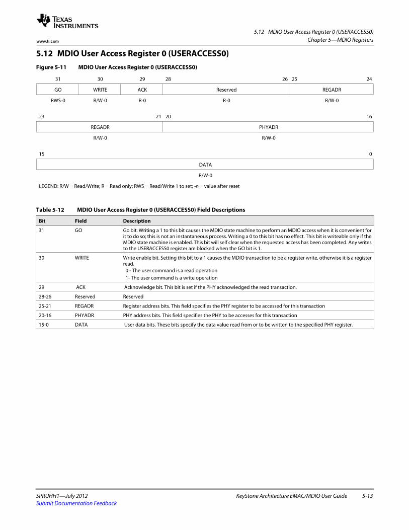
5.12 MDIO User Access Register 0 (USERACCESS0)
SPRUHH1—July 2012 KeyStone Architecture EMAC/MDIO User Guide 5-13Submit Documentation Feedback
Chapter 5—MDIO Registerswww.ti.com
5.12 MDIO User Access Register 0 (USERACCESS0)Figure 5-11 MDIO User Access Register 0 (USERACCESS0)
31 30 29 28 26 25 24
GO WRITE ACK Reserved REGADR
RWS-0 R/W-0 R-0 R-0 R/W-0
23 21 20 16
REGADR PHYADR
R/W-0 R/W-0
15 0
DATA
R/W-0
LEGEND: R/W = Read/Write; R = Read only; RWS = Read/Write 1 to set; -n = value after reset
Table 5-12 MDIO User Access Register 0 (USERACCESS0) Field Descriptions
Bit Field Description
31 GO Go bit. Writing a 1 to this bit causes the MDIO state machine to perform an MDIO access when it is convenient for it to do so; this is not an instantaneous process. Writing a 0 to this bit has no effect. This bit is writeable only if the MDIO state machine is enabled. This bit will self clear when the requested access has been completed. Any writes to the USERACCESS0 register are blocked when the GO bit is 1.
30 WRITE Write enable bit. Setting this bit to a 1 causes the MDIO transaction to be a register write, otherwise it is a register read.
0 - The user command is a read operation1- The user command is a write operation
29 ACK Acknowledge bit. This bit is set if the PHY acknowledged the read transaction.
28-26 Reserved Reserved
25-21 REGADR Register address bits. This field specifies the PHY register to be accessed for this transaction
20-16 PHYADR PHY address bits. This field specifies the PHY to be accesses for this transaction
15-0 DATA User data bits. These bits specify the data value read from or to be written to the specified PHY register.
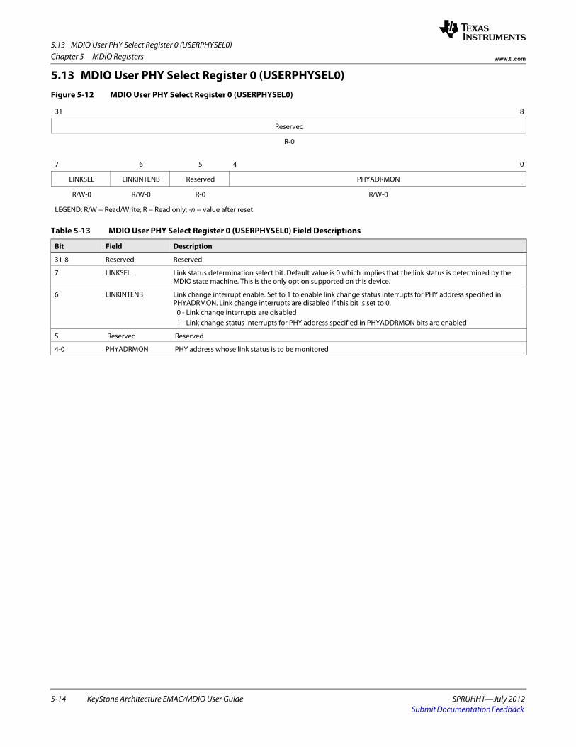
5.13 MDIO User PHY Select Register 0 (USERPHYSEL0)
5-14 KeyStone Architecture EMAC/MDIO User Guide SPRUHH1—July 2012Submit Documentation Feedback
Chapter 5—MDIO Registers www.ti.com
5.13 MDIO User PHY Select Register 0 (USERPHYSEL0)Figure 5-12 MDIO User PHY Select Register 0 (USERPHYSEL0)
31 8
Reserved
R-0
7 6 5 4 0
LINKSEL LINKINTENB Reserved PHYADRMON
R/W-0 R/W-0 R-0 R/W-0
LEGEND: R/W = Read/Write; R = Read only; -n = value after reset
Table 5-13 MDIO User PHY Select Register 0 (USERPHYSEL0) Field Descriptions
Bit Field Description
31-8 Reserved Reserved
7 LINKSEL Link status determination select bit. Default value is 0 which implies that the link status is determined by the MDIO state machine. This is the only option supported on this device.
6 LINKINTENB Link change interrupt enable. Set to 1 to enable link change status interrupts for PHY address specified in PHYADRMON. Link change interrupts are disabled if this bit is set to 0.
0 - Link change interrupts are disabled1 - Link change status interrupts for PHY address specified in PHYADDRMON bits are enabled
5 Reserved Reserved
4-0 PHYADRMON PHY address whose link status is to be monitored
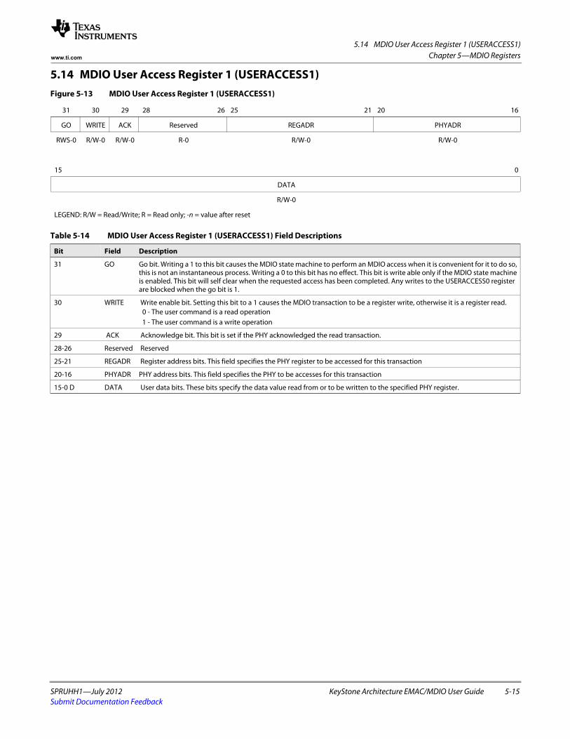
5.14 MDIO User Access Register 1 (USERACCESS1)
SPRUHH1—July 2012 KeyStone Architecture EMAC/MDIO User Guide 5-15Submit Documentation Feedback
Chapter 5—MDIO Registerswww.ti.com
5.14 MDIO User Access Register 1 (USERACCESS1)Figure 5-13 MDIO User Access Register 1 (USERACCESS1)
31 30 29 28 26 25 21 20 16
GO WRITE ACK Reserved REGADR PHYADR
RWS-0 R/W-0 R/W-0 R-0 R/W-0 R/W-0
15 0
DATA
R/W-0
LEGEND: R/W = Read/Write; R = Read only; -n = value after reset
Table 5-14 MDIO User Access Register 1 (USERACCESS1) Field Descriptions
Bit Field Description
31 GO Go bit. Writing a 1 to this bit causes the MDIO state machine to perform an MDIO access when it is convenient for it to do so, this is not an instantaneous process. Writing a 0 to this bit has no effect. This bit is write able only if the MDIO state machine is enabled. This bit will self clear when the requested access has been completed. Any writes to the USERACCESS0 register are blocked when the go bit is 1.
30 WRITE Write enable bit. Setting this bit to a 1 causes the MDIO transaction to be a register write, otherwise it is a register read.0 - The user command is a read operation1 - The user command is a write operation
29 ACK Acknowledge bit. This bit is set if the PHY acknowledged the read transaction.
28-26 Reserved Reserved
25-21 REGADR Register address bits. This field specifies the PHY register to be accessed for this transaction
20-16 PHYADR PHY address bits. This field specifies the PHY to be accesses for this transaction
15-0 D DATA User data bits. These bits specify the data value read from or to be written to the specified PHY register.
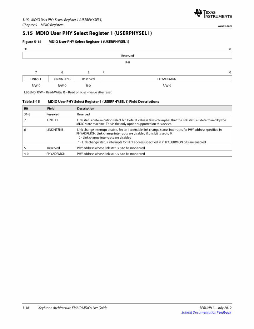
5.15 MDIO User PHY Select Register 1 (USERPHYSEL1)
5-16 KeyStone Architecture EMAC/MDIO User Guide SPRUHH1—July 2012Submit Documentation Feedback
Chapter 5—MDIO Registers www.ti.com
5.15 MDIO User PHY Select Register 1 (USERPHYSEL1)Figure 5-14 MDIO User PHY Select Register 1 (USERPHYSEL1)
31 8
Reserved
R-0
7 6 5 4 0
LINKSEL LINKINTENB Reserved PHYADRMON
R/W-0 R/W-0 R-0 R/W-0
LEGEND: R/W = Read/Write; R = Read only; -n = value after reset
Table 5-15 MDIO User PHY Select Register 1 (USERPHYSEL1) Field Descriptions
Bit Field Description
31-8 Reserved Reserved
7 LINKSEL Link status determination select bit. Default value is 0 which implies that the link status is determined by the MDIO state machine. This is the only option supported on this device.
6 LINKINTENB Link change interrupt enable. Set to 1 to enable link change status interrupts for PHY address specified in PHYADRMON. Link change interrupts are disabled if this bit is set to 0.
0 - Link change interrupts are disabled1 - Link change status interrupts for PHY address specified in PHYADDRMON bits are enabled
5 Reserved PHY address whose link status is to be monitored
4-0 PHYADRMON PHY address whose link status is to be monitored
SPRUHH1—July 2012 KeyStone Architecture EMAC/MDIO User Guide 6-1Submit Documentation Feedback
Chapter 6
SerDes Registers
This section describes the registers located in the SerDes boot configuration module that are related to the SGMII module. These registers are used to configure various settings required for use of the SerDes with the SGMII modules. The SerDes SGMII registers are located in the boot configuration module, which is external to the Ethernet switch subsystem. The SGMII SerDes addressing information is not provided in this manual, because the boot configuration memory map is device specific. For more information about the boot configuration registers, including addressing information, please see the device specific data sheet.
6.1 "Introduction" on page 6-2 6.2 "SGMII SerDes Status Register (SGMII_SERDES_STS)" on page 6-3 6.3 "SGMII SerDes PLL Configuration Register (SGMII_SERDES_CFGPLL)" on page 6-4 6.4 "SGMII SerDes Receive Configuration Register 0 (SGMII_SERDES_CFGRX0)" on
page 6-6 6.5 "SGMII SerDes Transmit Configuration Register 0 (SGMII_SERDES_CFGTX0)" on
page 6-8
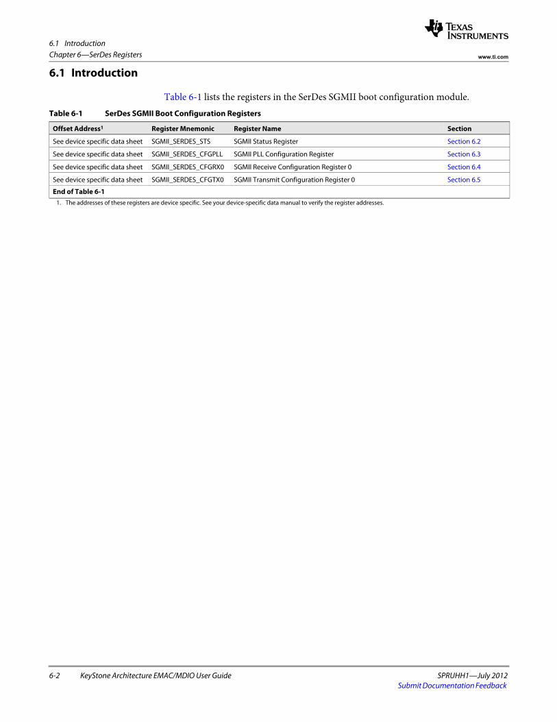
6.1 Introduction
6-2 KeyStone Architecture EMAC/MDIO User Guide SPRUHH1—July 2012Submit Documentation Feedback
Chapter 6—SerDes Registers www.ti.com
6.1 Introduction
Table 6-1 lists the registers in the SerDes SGMII boot configuration module.Table 6-1 SerDes SGMII Boot Configuration Registers
Offset Address1 Register Mnemonic Register Name Section
See device specific data sheet SGMII_SERDES_STS SGMII Status Register Section 6.2
See device specific data sheet SGMII_SERDES_CFGPLL SGMII PLL Configuration Register Section 6.3
See device specific data sheet SGMII_SERDES_CFGRX0 SGMII Receive Configuration Register 0 Section 6.4
See device specific data sheet SGMII_SERDES_CFGTX0 SGMII Transmit Configuration Register 0 Section 6.5
End of Table 6-11. The addresses of these registers are device specific. See your device-specific data manual to verify the register addresses.
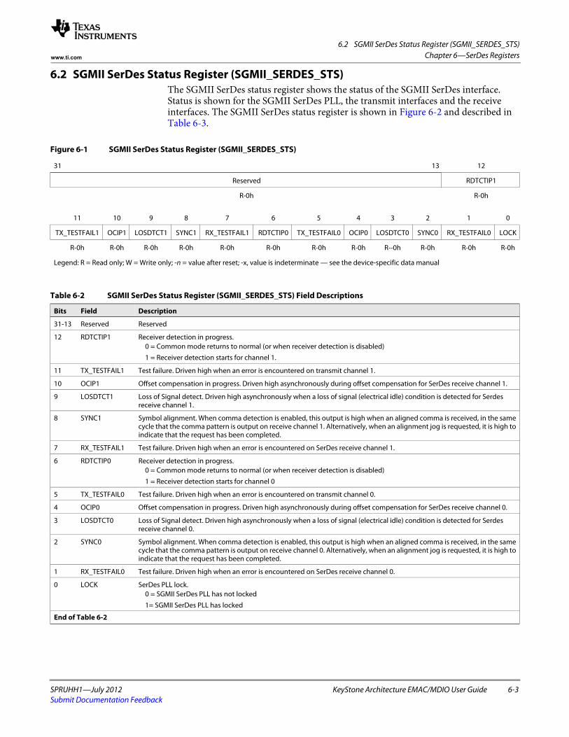
6.2 SGMII SerDes Status Register (SGMII_SERDES_STS)
SPRUHH1—July 2012 KeyStone Architecture EMAC/MDIO User Guide 6-3Submit Documentation Feedback
Chapter 6—SerDes Registerswww.ti.com
6.2 SGMII SerDes Status Register (SGMII_SERDES_STS)The SGMII SerDes status register shows the status of the SGMII SerDes interface. Status is shown for the SGMII SerDes PLL, the transmit interfaces and the receive interfaces. The SGMII SerDes status register is shown in Figure 6-2 and described in Table 6-3.
Figure 6-1 SGMII SerDes Status Register (SGMII_SERDES_STS)
31 13 12
Reserved RDTCTIP1
R-0h R-0hspacer
11 10 9 8 7 6 5 4 3 2 1 0
TX_TESTFAIL1 OCIP1 LOSDTCT1 SYNC1 RX_TESTFAIL1 RDTCTIP0 TX_TESTFAIL0 OCIP0 LOSDTCT0 SYNC0 RX_TESTFAIL0 LOCK
R-0h R-0h R-0h R-0h R-0h R-0h R-0h R-0h R--0h R-0h R-0h R-0h
Legend: R = Read only; W = Write only; -n = value after reset; -x, value is indeterminate — see the device-specific data manual
Table 6-2 SGMII SerDes Status Register (SGMII_SERDES_STS) Field Descriptions
Bits Field Description
31-13 Reserved Reserved
12 RDTCTIP1 Receiver detection in progress. 0 = Common mode returns to normal (or when receiver detection is disabled)
1 = Receiver detection starts for channel 1.
11 TX_TESTFAIL1 Test failure. Driven high when an error is encountered on transmit channel 1.
10 OCIP1 Offset compensation in progress. Driven high asynchronously during offset compensation for SerDes receive channel 1.
9 LOSDTCT1 Loss of Signal detect. Driven high asynchronously when a loss of signal (electrical idle) condition is detected for Serdes receive channel 1.
8 SYNC1 Symbol alignment. When comma detection is enabled, this output is high when an aligned comma is received, in the same cycle that the comma pattern is output on receive channel 1. Alternatively, when an alignment jog is requested, it is high to indicate that the request has been completed.
7 RX_TESTFAIL1 Test failure. Driven high when an error is encountered on SerDes receive channel 1.
6 RDTCTIP0 Receiver detection in progress. 0 = Common mode returns to normal (or when receiver detection is disabled)
1 = Receiver detection starts for channel 0
5 TX_TESTFAIL0 Test failure. Driven high when an error is encountered on transmit channel 0.
4 OCIP0 Offset compensation in progress. Driven high asynchronously during offset compensation for SerDes receive channel 0.
3 LOSDTCT0 Loss of Signal detect. Driven high asynchronously when a loss of signal (electrical idle) condition is detected for Serdes receive channel 0.
2 SYNC0 Symbol alignment. When comma detection is enabled, this output is high when an aligned comma is received, in the same cycle that the comma pattern is output on receive channel 0. Alternatively, when an alignment jog is requested, it is high to indicate that the request has been completed.
1 RX_TESTFAIL0 Test failure. Driven high when an error is encountered on SerDes receive channel 0.
0 LOCK SerDes PLL lock. 0 = SGMII SerDes PLL has not locked
1= SGMII SerDes PLL has locked
End of Table 6-2
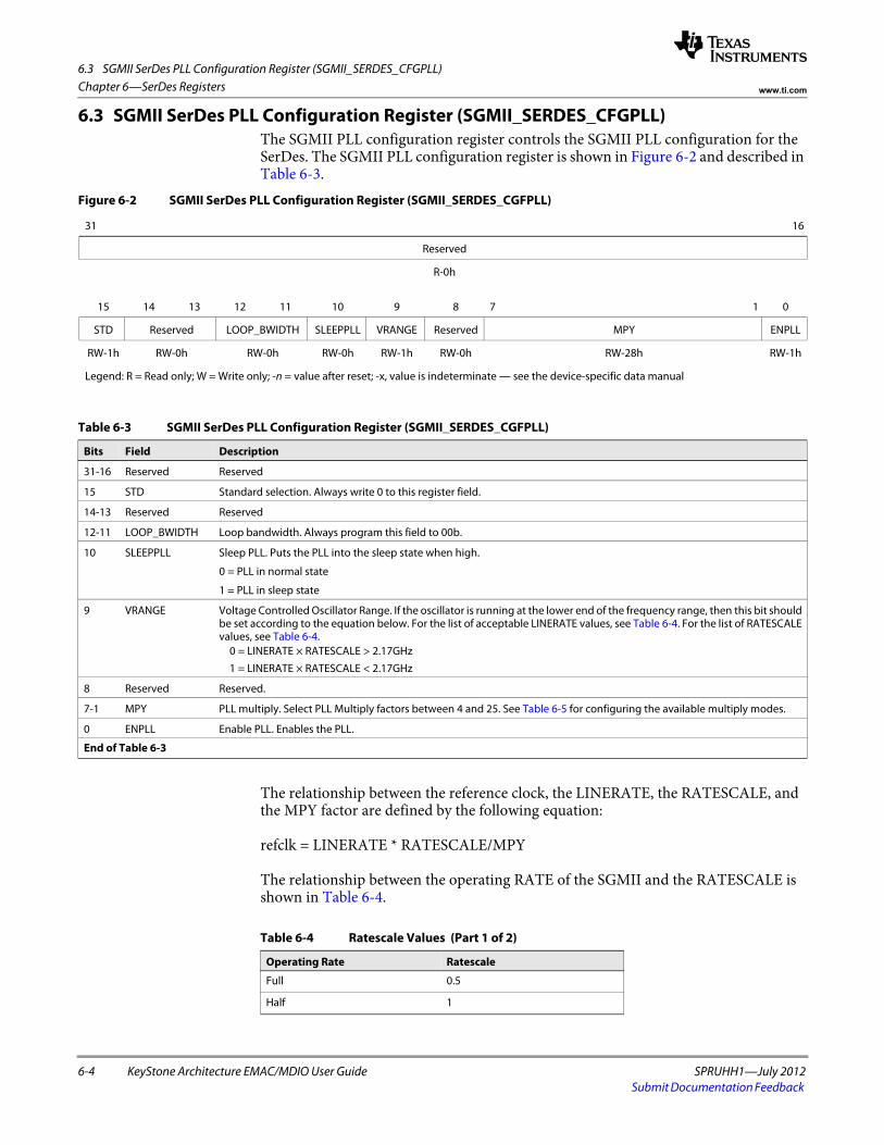
6.3 SGMII SerDes PLL Configuration Register (SGMII_SERDES_CFGPLL)
6-4 KeyStone Architecture EMAC/MDIO User Guide SPRUHH1—July 2012Submit Documentation Feedback
Chapter 6—SerDes Registers www.ti.com
6.3 SGMII SerDes PLL Configuration Register (SGMII_SERDES_CFGPLL)The SGMII PLL configuration register controls the SGMII PLL configuration for the SerDes. The SGMII PLL configuration register is shown in Figure 6-2 and described in Table 6-3.
The relationship between the reference clock, the LINERATE, the RATESCALE, and the MPY factor are defined by the following equation:
refclk = LINERATE * RATESCALE/MPY
The relationship between the operating RATE of the SGMII and the RATESCALE is shown in Table 6-4.
Figure 6-2 SGMII SerDes PLL Configuration Register (SGMII_SERDES_CGFPLL)
31 16
Reserved
R-0hspacer
15 14 13 12 11 10 9 8 7 1 0
STD Reserved LOOP_BWIDTH SLEEPPLL VRANGE Reserved MPY ENPLL
RW-1h RW-0h RW-0h RW-0h RW-1h RW-0h RW-28h RW-1h
Legend: R = Read only; W = Write only; -n = value after reset; -x, value is indeterminate — see the device-specific data manual
Table 6-3 SGMII SerDes PLL Configuration Register (SGMII_SERDES_CGFPLL)
Bits Field Description
31-16 Reserved Reserved
15 STD Standard selection. Always write 0 to this register field.
14-13 Reserved Reserved
12-11 LOOP_BWIDTH Loop bandwidth. Always program this field to 00b.
10 SLEEPPLL Sleep PLL. Puts the PLL into the sleep state when high.
0 = PLL in normal state
1 = PLL in sleep state
9 VRANGE Voltage Controlled Oscillator Range. If the oscillator is running at the lower end of the frequency range, then this bit should be set according to the equation below. For the list of acceptable LINERATE values, see Table 6-4. For the list of RATESCALE values, see Table 6-4.
0 = LINERATE × RATESCALE > 2.17GHz
1 = LINERATE × RATESCALE < 2.17GHz
8 Reserved Reserved.
7-1 MPY PLL multiply. Select PLL Multiply factors between 4 and 25. See Table 6-5 for configuring the available multiply modes.
0 ENPLL Enable PLL. Enables the PLL.
End of Table 6-3
Table 6-4 Ratescale Values (Part 1 of 2)
Operating Rate Ratescale
Full 0.5
Half 1
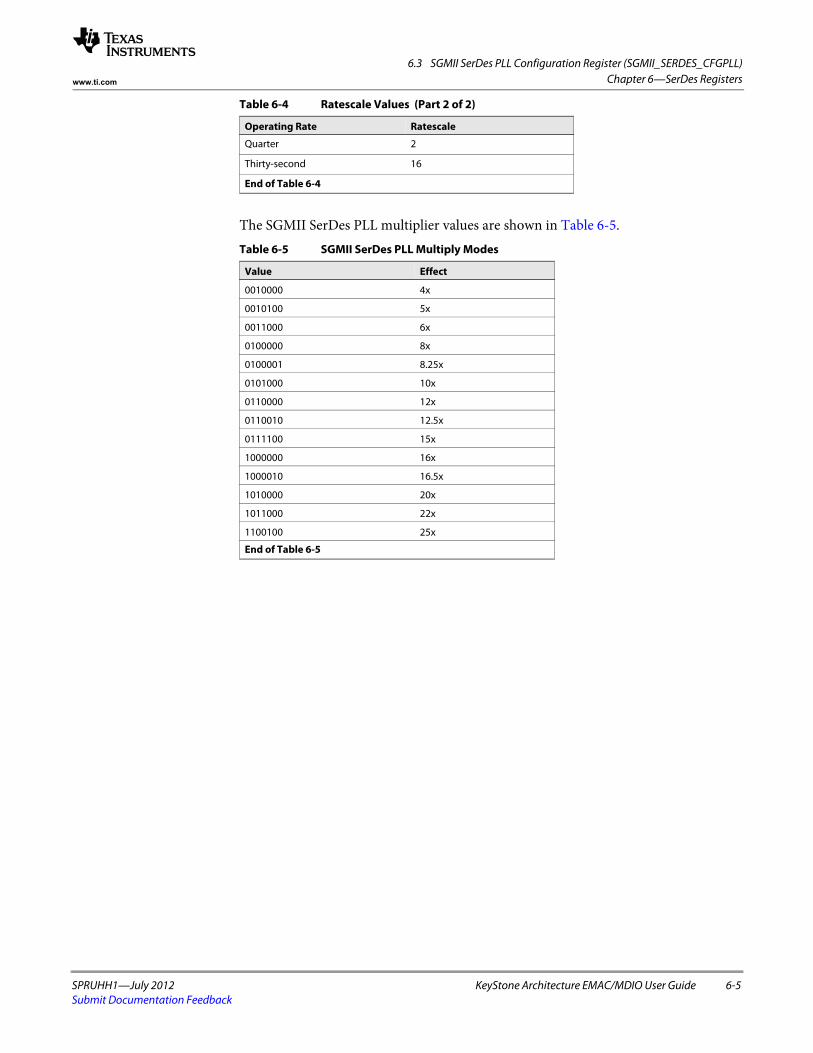
6.3 SGMII SerDes PLL Configuration Register (SGMII_SERDES_CFGPLL)
SPRUHH1—July 2012 KeyStone Architecture EMAC/MDIO User Guide 6-5Submit Documentation Feedback
Chapter 6—SerDes Registerswww.ti.com
The SGMII SerDes PLL multiplier values are shown in Table 6-5.
Quarter 2
Thirty-second 16
End of Table 6-4
Table 6-5 SGMII SerDes PLL Multiply Modes
Value Effect
0010000 4x
0010100 5x
0011000 6x
0100000 8x
0100001 8.25x
0101000 10x
0110000 12x
0110010 12.5x
0111100 15x
1000000 16x
1000010 16.5x
1010000 20x
1011000 22x
1100100 25x
End of Table 6-5
Table 6-4 Ratescale Values (Part 2 of 2)
Operating Rate Ratescale
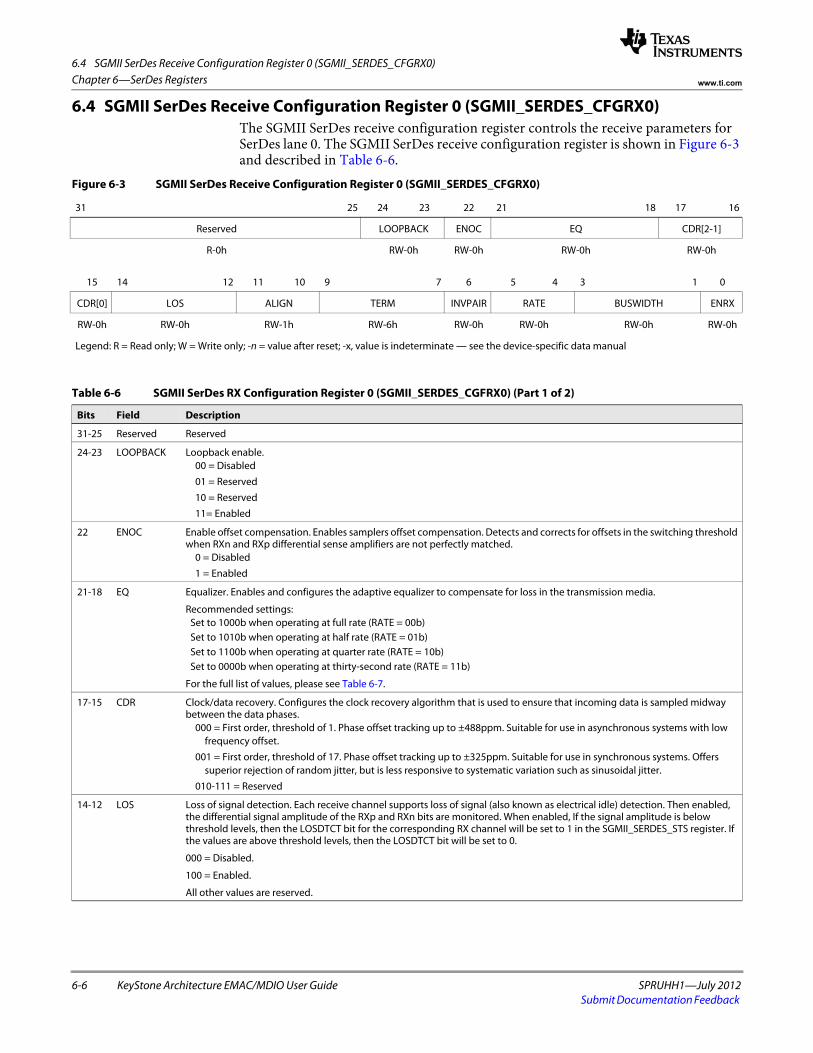
6.4 SGMII SerDes Receive Configuration Register 0 (SGMII_SERDES_CFGRX0)
6-6 KeyStone Architecture EMAC/MDIO User Guide SPRUHH1—July 2012Submit Documentation Feedback
Chapter 6—SerDes Registers www.ti.com
6.4 SGMII SerDes Receive Configuration Register 0 (SGMII_SERDES_CFGRX0)The SGMII SerDes receive configuration register controls the receive parameters for SerDes lane 0. The SGMII SerDes receive configuration register is shown in Figure 6-3 and described in Table 6-6.
Figure 6-3 SGMII SerDes Receive Configuration Register 0 (SGMII_SERDES_CFGRX0)
31 25 24 23 22 21 18 17 16
Reserved LOOPBACK ENOC EQ CDR[2-1]
R-0h RW-0h RW-0h RW-0h RW-0hspacer
15 14 12 11 10 9 7 6 5 4 3 1 0
CDR[0] LOS ALIGN TERM INVPAIR RATE BUSWIDTH ENRX
RW-0h RW-0h RW-1h RW-6h RW-0h RW-0h RW-0h RW-0h
Legend: R = Read only; W = Write only; -n = value after reset; -x, value is indeterminate — see the device-specific data manual
Table 6-6 SGMII SerDes RX Configuration Register 0 (SGMII_SERDES_CGFRX0) (Part 1 of 2)
Bits Field Description
31-25 Reserved Reserved
24-23 LOOPBACK Loopback enable.00 = Disabled
01 = Reserved
10 = Reserved
11= Enabled
22 ENOC Enable offset compensation. Enables samplers offset compensation. Detects and corrects for offsets in the switching threshold when RXn and RXp differential sense amplifiers are not perfectly matched.
0 = Disabled
1 = Enabled
21-18 EQ Equalizer. Enables and configures the adaptive equalizer to compensate for loss in the transmission media.
Recommended settings:Set to 1000b when operating at full rate (RATE = 00b)Set to 1010b when operating at half rate (RATE = 01b)Set to 1100b when operating at quarter rate (RATE = 10b)Set to 0000b when operating at thirty-second rate (RATE = 11b)
For the full list of values, please see Table 6-7.
17-15 CDR Clock/data recovery. Configures the clock recovery algorithm that is used to ensure that incoming data is sampled midway between the data phases.
000 = First order, threshold of 1. Phase offset tracking up to ±488ppm. Suitable for use in asynchronous systems with low frequency offset.
001 = First order, threshold of 17. Phase offset tracking up to ±325ppm. Suitable for use in synchronous systems. Offers superior rejection of random jitter, but is less responsive to systematic variation such as sinusoidal jitter.
010-111 = Reserved
14-12 LOS Loss of signal detection. Each receive channel supports loss of signal (also known as electrical idle) detection. Then enabled, the differential signal amplitude of the RXp and RXn bits are monitored. When enabled, If the signal amplitude is below threshold levels, then the LOSDTCT bit for the corresponding RX channel will be set to 1 in the SGMII_SERDES_STS register. If the values are above threshold levels, then the LOSDTCT bit will be set to 0.
000 = Disabled.
100 = Enabled.
All other values are reserved.
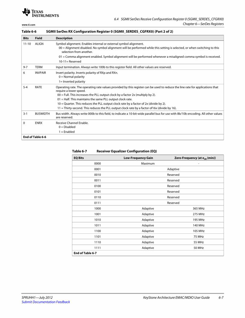
6.4 SGMII SerDes Receive Configuration Register 0 (SGMII_SERDES_CFGRX0)
SPRUHH1—July 2012 KeyStone Architecture EMAC/MDIO User Guide 6-7Submit Documentation Feedback
Chapter 6—SerDes Registerswww.ti.com
11-10 ALIGN Symbol alignment. Enables internal or external symbol alignment. 00 = Alignment disabled. No symbol alignment will be performed while this setting is selected, or when switching to this
selection from another.
01 = Comma alignment enabled. Symbol alignment will be performed whenever a misaligned comma symbol is received.
10-11= Reserved
9-7 TERM Input termination. Always write 100b to this register field. All other values are reserved.
6 INVPAIR Invert polarity. Inverts polarity of RXp and RXn.0 = Normal polarity
1= Inverted polarity
5-4 RATE Operating rate. The operating rate values provided by this register can be used to reduce the line rate for applications that require a lower speed.
00 = Full. This increases the PLL output clock by a factor 2x (multiply by 2).01 = Half. This maintains the same PLL output clock rate.10 = Quarter. This reduces the PLL output clock rate by a factor of 2x (divide by 2).11 = Thirty-second. This reduces the PLL output clock rate by a factor of16x (divide by 16).
3-1 BUSWIDTH Bus width. Always write 000b to this field, to indicate a 10-bit-wide parallel bus for use with 8b/10b encoding. All other values are reserved.
0 ENRX Receive Channel Enable. 0 = Disabled
1 = Enabled
End of Table 6-6
Table 6-6 SGMII SerDes RX Configuration Register 0 (SGMII_SERDES_CGFRX0) (Part 2 of 2)
Bits Field Description
Table 6-7 Receiver Equalizer Configuration (EQ)
EQ Bits Low-Frequency Gain Zero-Frequency (at e28 (min))
0000 Maximum -
0001 Adaptive
0010 Reserved
0011 Reserved
0100 Reserved
0101 Reserved
0110 Reserved
0111 Reserved
1000 Adaptive 365 MHz
1001 Adaptive 275 MHz
1010 Adaptive 195 MHz
1011 Adaptive 140 MHz
1100 Adaptive 105 MHz
1101 Adaptive 75 MHz
1110 Adaptive 55 MHz
1111 Adaptive 50 MHz
End of Table 6-7
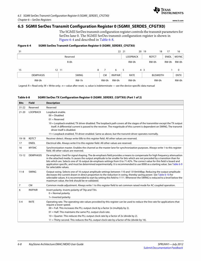
6.5 SGMII SerDes Transmit Configuration Register 0 (SGMII_SERDES_CFGTX0)
6-8 KeyStone Architecture EMAC/MDIO User Guide SPRUHH1—July 2012Submit Documentation Feedback
Chapter 6—SerDes Registers www.ti.com
6.5 SGMII SerDes Transmit Configuration Register 0 (SGMII_SERDES_CFGTX0)The SGMII SerDes transmit configuration register controls the transmit parameters for SerDes lane 0. The SGMII SerDes transmit configuration register is shown in Figure 6-4 and described in Table 6-8.
Figure 6-4 SGMII SerDes Transmit Configuration Register 0 (SGMII_SERDES_CFGTX0)
31 22 21 20 19 18 17 16
Reserved LOOPBACK RDTCT ENIDL MSYNC
R-0h RW-0h RW-0h RW-0h RW-0hspacer
15 12 11 8 7 6 5 4 3 1 0
DEMPHASIS SWING CM INVPAIR RATE BUSWIDTH ENTX
RW-0h RW-1h RW-0h RW-0h RW-0h RW-0h RW-0h
Legend: R = Read only; W = Write only; -n = value after reset; -x, value is indeterminate — see the device-specific data manual
Table 6-8 SGMII SerDes TX Configuration Register 0 (SGMII_SERDES_CGFTX0) (Part 1 of 2)
Bits Field Description
31-22 Reserved Reserved
21-20 LOOPBACK Loopback enable.00 = Disabled
01 = Reserved
10 = Loopback enabled, TX driver disabled. The loopback path covers all the stages of the transmitter except the TX output itself. A differential current is passed to the receiver. The magnitude of this current is dependent on SWING. The transmit driver itself is disabled.
11= Loopback enabled, TX driver enabled. Same as above, but the transmit driver operates normally.
19-18 RDTCT Receiver detect. Always write 00b to this register field. All other values are reserved.
17 ENIDL Electrical idle. Always write 0 to this register field. All other values are reserved.
16 MYSNC Synchronization master. Enables the channel as the master lane for synchronization purposes. Always write 1 to this register field. All other values are reserved.
15-12 DEMPHASIS De-emphasis. Used for signal shaping. The de-emphasis field provides a means to compensate for high frequency attenuation in the attached media. It causes the output amplitude to be smaller for bits which are not preceded by a transition than for bits which are. Selects one of 16 output de-emphasis settings from 0 to 71.42%. The correct value for this field is board and application specific, and must be determined experimentally. It is recommended to use 0000 as a starting value. See Table 6-9 for selectable values.
11-8 SWING Output swing. Selects one of 16 output amplitude settings between 110 and 1310mVdfpp. Reducing the output amplitude decreases the current drawn in direct proportion to the reduction in swing, thereby saving power. See Table 6-10 for selectable values. It is recommended to start by setting this field to 1111. Whenever the SWING is reduced to a level below the maximum value, the link should be re-validated.
7 CM Common mode adjustment. Always write 1 to this register field to set common raised mode for AC coupled operation.
6 INVPAIR Invert polarity. Inverts polarity of TXp and TXn.0 = Normal polarity
1= Inverted polarity
5-4 RATE Operating rate. The operating rate values provided by this register can be used to reduce the line rate for applications that require a lower speed.
00 = Full. This increases the PLL output clock by a factor 2x (multiply by 2).
01 = Half. This maintains the same PLL output clock rate.
10 = Quarter. This reduces the PLL output clock rate by a factor of 2x (divide by 2).
11 = Thirty-second. This reduces the PLL output clock rate by a factor of16x (divide by 16).
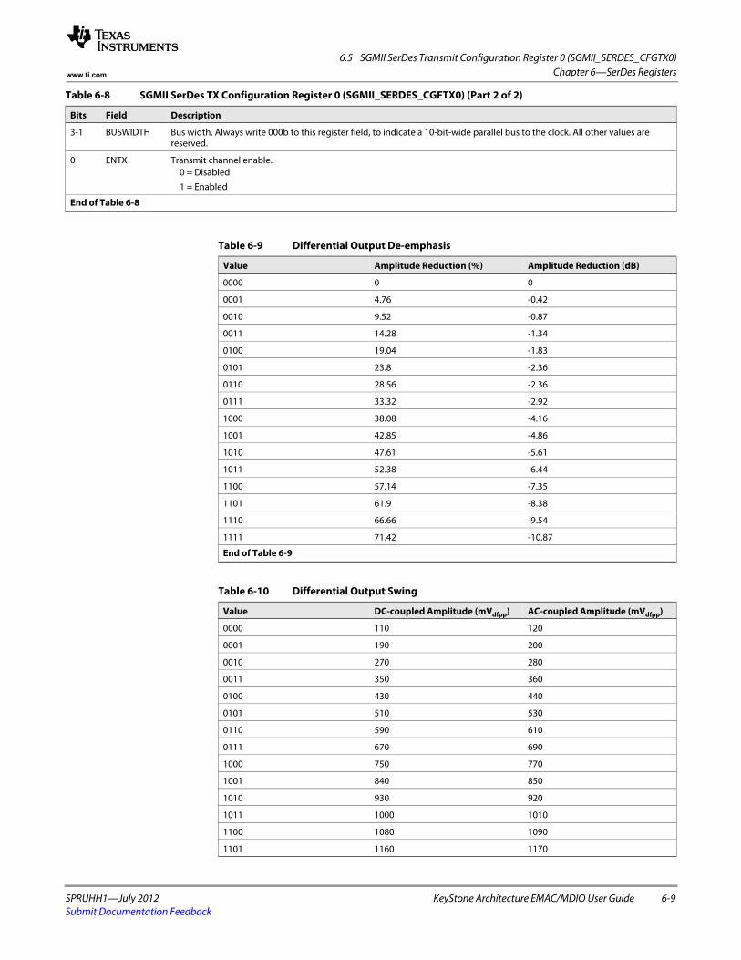
6.5 SGMII SerDes Transmit Configuration Register 0 (SGMII_SERDES_CFGTX0)
SPRUHH1—July 2012 KeyStone Architecture EMAC/MDIO User Guide 6-9Submit Documentation Feedback
Chapter 6—SerDes Registerswww.ti.com
3-1 BUSWIDTH Bus width. Always write 000b to this register field, to indicate a 10-bit-wide parallel bus to the clock. All other values are reserved.
0 ENTX Transmit channel enable. 0 = Disabled
1 = Enabled
End of Table 6-8
Table 6-8 SGMII SerDes TX Configuration Register 0 (SGMII_SERDES_CGFTX0) (Part 2 of 2)
Bits Field Description
Table 6-9 Differential Output De-emphasis
Value Amplitude Reduction (%) Amplitude Reduction (dB)
0000 0 0
0001 4.76 -0.42
0010 9.52 -0.87
0011 14.28 -1.34
0100 19.04 -1.83
0101 23.8 -2.36
0110 28.56 -2.36
0111 33.32 -2.92
1000 38.08 -4.16
1001 42.85 -4.86
1010 47.61 -5.61
1011 52.38 -6.44
1100 57.14 -7.35
1101 61.9 -8.38
1110 66.66 -9.54
1111 71.42 -10.87
End of Table 6-9
Table 6-10 Differential Output Swing
Value DC-coupled Amplitude (mVdfpp) AC-coupled Amplitude (mVdfpp)
0000 110 120
0001 190 200
0010 270 280
0011 350 360
0100 430 440
0101 510 530
0110 590 610
0111 670 690
1000 750 770
1001 840 850
1010 930 920
1011 1000 1010
1100 1080 1090
1101 1160 1170
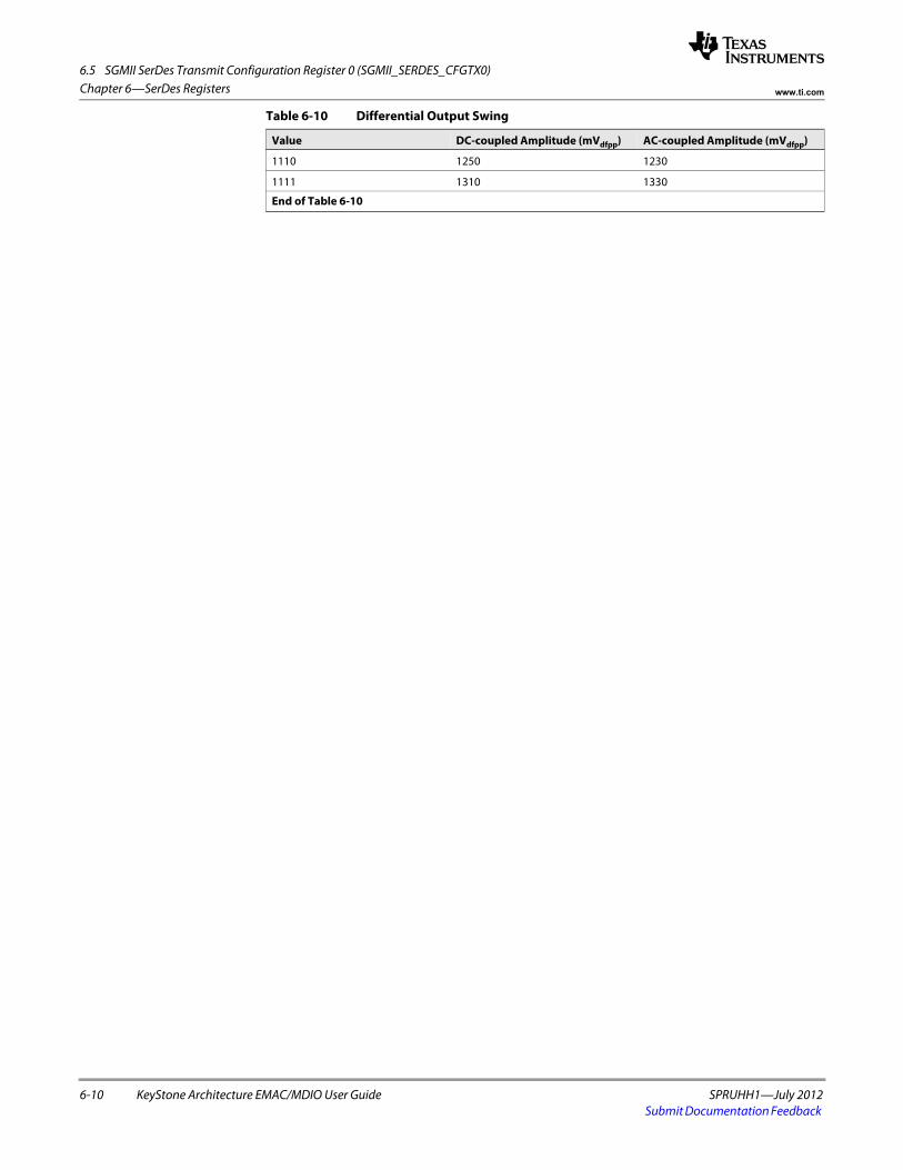
6.5 SGMII SerDes Transmit Configuration Register 0 (SGMII_SERDES_CFGTX0)
6-10 KeyStone Architecture EMAC/MDIO User Guide SPRUHH1—July 2012Submit Documentation Feedback
Chapter 6—SerDes Registers www.ti.com
1110 1250 1230
1111 1310 1330
End of Table 6-10
Table 6-10 Differential Output Swing
Value DC-coupled Amplitude (mVdfpp) AC-coupled Amplitude (mVdfpp)
SPRUHH1—July 2012 KeyStone Architecture EMAC/MDIO User Guide 7-1Submit Documentation Feedback
Chapter 7
SGMII Registers
7.1 "Introduction" on page 7-2 7.2 "Identification and Version Register (IDVER)" on page 7-3 7.3 "Software Reset Register (SOFT_RESET)" on page 7-4 7.4 "Control Register (CONTROL)" on page 7-5 7.5 "Status Register (STATUS)" on page 7-6 7.6 "Advertised Ability Register (MR_ADV_ABILITY)" on page 7-7 7.7 "Link Partner Advertised Ability Register (MR_LP_AD V_ABILITY)" on page 7-8
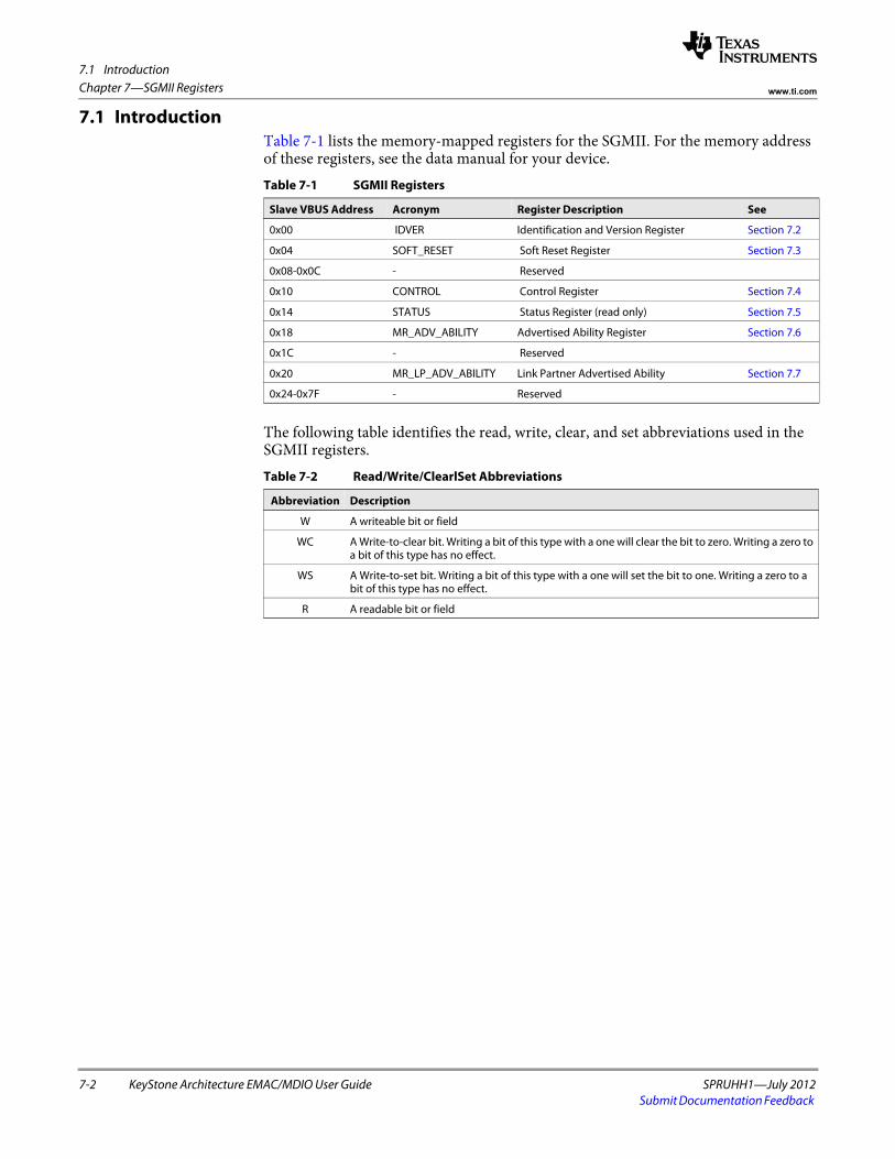
7.1 Introduction
7-2 KeyStone Architecture EMAC/MDIO User Guide SPRUHH1—July 2012Submit Documentation Feedback
Chapter 7—SGMII Registers www.ti.com
7.1 IntroductionTable 7-1 lists the memory-mapped registers for the SGMII. For the memory address of these registers, see the data manual for your device.
The following table identifies the read, write, clear, and set abbreviations used in the SGMII registers.
Table 7-1 SGMII Registers
Slave VBUS Address Acronym Register Description See
0x00 IDVER Identification and Version Register Section 7.2
0x04 SOFT_RESET Soft Reset Register Section 7.3
0x08-0x0C - Reserved
0x10 CONTROL Control Register Section 7.4
0x14 STATUS Status Register (read only) Section 7.5
0x18 MR_ADV_ABILITY Advertised Ability Register Section 7.6
0x1C - Reserved
0x20 MR_LP_ADV_ABILITY Link Partner Advertised Ability Section 7.7
0x24-0x7F - Reserved
Table 7-2 Read/Write/ClearlSet Abbreviations
Abbreviation Description
W A writeable bit or field
WC A Write-to-clear bit. Writing a bit of this type with a one will clear the bit to zero. Writing a zero to a bit of this type has no effect.
WS A Write-to-set bit. Writing a bit of this type with a one will set the bit to one. Writing a zero to a bit of this type has no effect.
R A readable bit or field
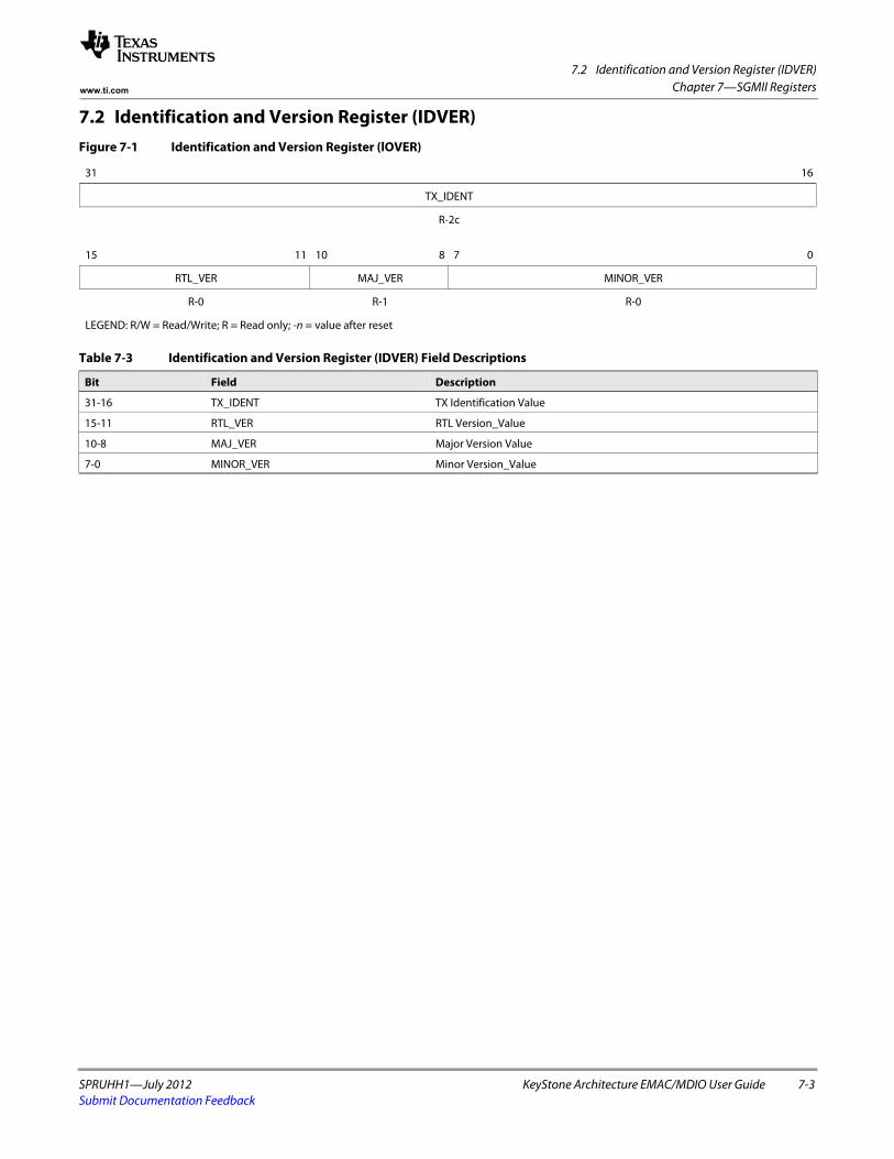
7.2 Identification and Version Register (IDVER)
SPRUHH1—July 2012 KeyStone Architecture EMAC/MDIO User Guide 7-3Submit Documentation Feedback
Chapter 7—SGMII Registerswww.ti.com
7.2 Identification and Version Register (IDVER)Figure 7-1 Identification and Version Register (lOVER)
31 16
TX_IDENT
R-2cspacer
15 11 10 8 7 0
RTL_VER MAJ_VER MINOR_VER
R-0 R-1 R-0
LEGEND: R/W = Read/Write; R = Read only; -n = value after reset
Table 7-3 Identification and Version Register (IDVER) Field Descriptions
Bit Field Description
31-16 TX_IDENT TX Identification Value
15-11 RTL_VER RTL Version_Value
10-8 MAJ_VER Major Version Value
7-0 MINOR_VER Minor Version_Value
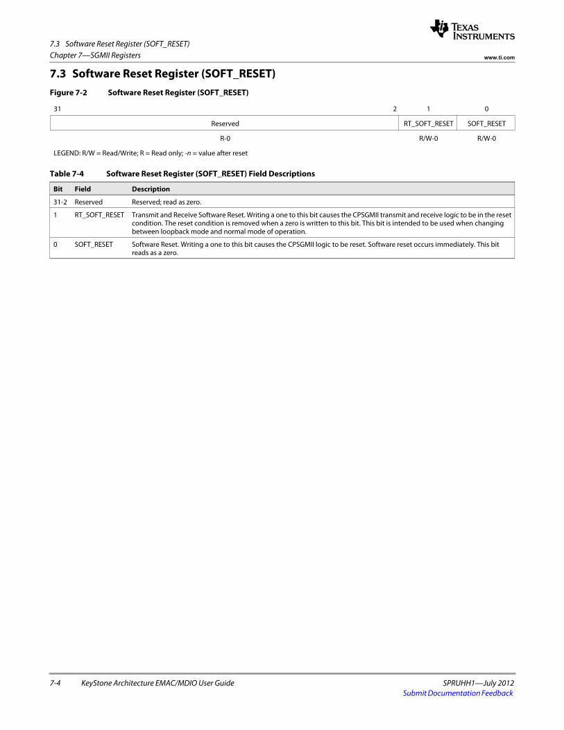
7.3 Software Reset Register (SOFT_RESET)
7-4 KeyStone Architecture EMAC/MDIO User Guide SPRUHH1—July 2012Submit Documentation Feedback
Chapter 7—SGMII Registers www.ti.com
7.3 Software Reset Register (SOFT_RESET)Figure 7-2 Software Reset Register (SOFT_RESET)
31 2 1 0
Reserved RT_SOFT_RESET SOFT_RESET
R-0 R/W-0 R/W-0
LEGEND: R/W = Read/Write; R = Read only; -n = value after reset
Table 7-4 Software Reset Register (SOFT_RESET) Field Descriptions
Bit Field Description
31-2 Reserved Reserved; read as zero.
1 RT_SOFT_RESET Transmit and Receive Software Reset. Writing a one to this bit causes the CPSGMII transmit and receive logic to be in the reset condition. The reset condition is removed when a zero is written to this bit. This bit is intended to be used when changing between loopback mode and normal mode of operation.
0 SOFT_RESET Software Reset. Writing a one to this bit causes the CPSGMII logic to be reset. Software reset occurs immediately. This bit reads as a zero.
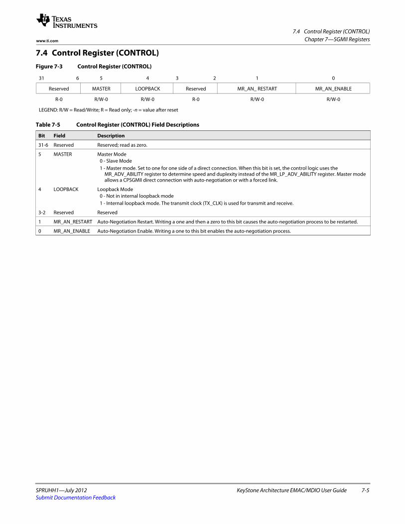
7.4 Control Register (CONTROL)
SPRUHH1—July 2012 KeyStone Architecture EMAC/MDIO User Guide 7-5Submit Documentation Feedback
Chapter 7—SGMII Registerswww.ti.com
7.4 Control Register (CONTROL)Figure 7-3 Control Register (CONTROL)
31 6 5 4 3 2 1 0
Reserved MASTER LOOPBACK Reserved MR_AN_ RESTART MR_AN_ENABLE
R-0 R/W-0 R/W-0 R-0 R/W-0 R/W-0
LEGEND: R/W = Read/Write; R = Read only; -n = value after reset
Table 7-5 Control Register (CONTROL) Field Descriptions
Bit Field Description
31-6 Reserved Reserved; read as zero.
5 MASTER Master Mode 0 - Slave Mode 1 - Master mode. Set to one for one side of a direct connection. When this bit is set, the control logic uses the
MR_ADV_ABILITY register to determine speed and duplexity instead of the MR_LP_ADV_ABILITY register. Master mode allows a CPSGMII direct connection with auto-negotiation or with a forced link.
4 LOOPBACK Loopback Mode 0 - Not in internal loopback mode 1 - Internal loopback mode. The transmit clock (TX_CLK) is used for transmit and receive.
3-2 Reserved Reserved
1 MR_AN_RESTART Auto-Negotiation Restart. Writing a one and then a zero to this bit causes the auto-negotiation process to be restarted.
0 MR_AN_ENABLE Auto-Negotiation Enable. Writing a one to this bit enables the auto-negotiation process.
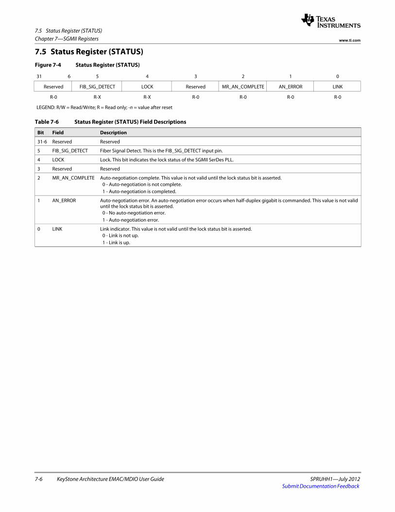
7.5 Status Register (STATUS)
7-6 KeyStone Architecture EMAC/MDIO User Guide SPRUHH1—July 2012Submit Documentation Feedback
Chapter 7—SGMII Registers www.ti.com
7.5 Status Register (STATUS)Figure 7-4 Status Register (STATUS)
31 6 5 4 3 2 1 0
Reserved FIB_SIG_DETECT LOCK Reserved MR_AN_COMPLETE AN_ERROR LINK
R-0 R-X R-X R-0 R-0 R-0 R-0
LEGEND: R/W = Read/Write; R = Read only; -n = value after reset
Table 7-6 Status Register (STATUS) Field Descriptions
Bit Field Description
31-6 Reserved Reserved
5 FIB_SIG_DETECT Fiber Signal Detect. This is the FIB_SIG_DETECT input pin.
4 LOCK Lock. This bit indicates the lock status of the SGMII SerDes PLL.
3 Reserved Reserved
2 MR_AN_COMPLETE Auto-negotiation complete. This value is not valid until the lock status bit is asserted. 0 - Auto-negotiation is not complete. 1 - Auto-negotiation is completed.
1 AN_ERROR Auto-negotiation error. An auto-negotiation error occurs when half-duplex gigabit is commanded. This value is not valid until the lock status bit is asserted.
0 - No auto-negotiation error. 1 - Auto-negotiation error.
0 LINK Link indicator. This value is not valid until the lock status bit is asserted. 0 - Link is not up. 1 - Link is up.
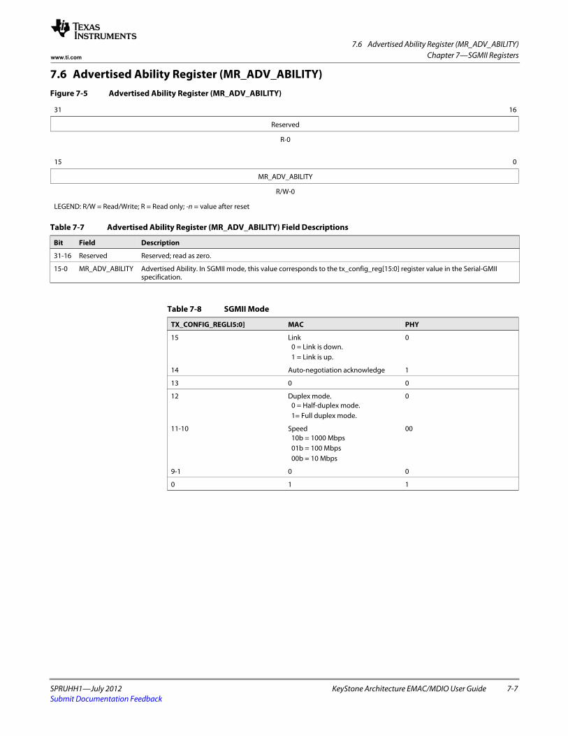
7.6 Advertised Ability Register (MR_ADV_ABILITY)
SPRUHH1—July 2012 KeyStone Architecture EMAC/MDIO User Guide 7-7Submit Documentation Feedback
Chapter 7—SGMII Registerswww.ti.com
7.6 Advertised Ability Register (MR_ADV_ABILITY)Figure 7-5 Advertised Ability Register (MR_ADV_ABILITY)
31 16
Reserved
R-0spacer
15 0
MR_ADV_ABILITY
R/W-0
LEGEND: R/W = Read/Write; R = Read only; -n = value after reset
Table 7-7 Advertised Ability Register (MR_ADV_ABILITY) Field Descriptions
Bit Field Description
31-16 Reserved Reserved; read as zero.
15-0 MR_ADV_ABILITY Advertised Ability. In SGMII mode, this value corresponds to the tx_config_reg[15:0] register value in the Serial-GMII specification.
Table 7-8 SGMII Mode
TX_CONFIG_REGLI5:0] MAC PHY
15 Link 0 = Link is down.1 = Link is up.
0
14 Auto-negotiation acknowledge 1
13 0 0
12 Duplex mode.0 = Half-duplex mode. 1= Full duplex mode.
0
11-10 Speed 10b = 1000 Mbps01b = 100 Mbps00b = 10 Mbps
00
9-1 0 0
0 1 1
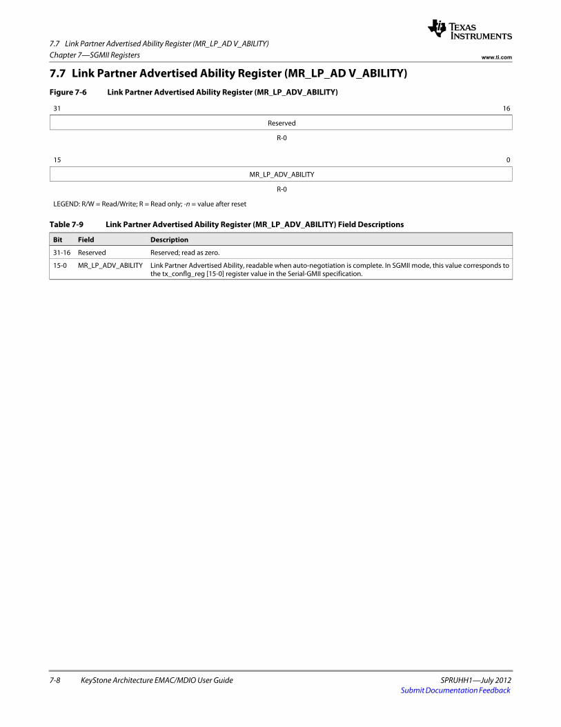
7.7 Link Partner Advertised Ability Register (MR_LP_AD V_ABILITY)
7-8 KeyStone Architecture EMAC/MDIO User Guide SPRUHH1—July 2012Submit Documentation Feedback
Chapter 7—SGMII Registers www.ti.com
7.7 Link Partner Advertised Ability Register (MR_LP_AD V_ABILITY)Figure 7-6 Link Partner Advertised Ability Register (MR_LP_ADV_ABILITY)
31 16
Reserved
R-0spacer
15 0
MR_LP_ADV_ABILITY
R-0
LEGEND: R/W = Read/Write; R = Read only; -n = value after reset
Table 7-9 Link Partner Advertised Ability Register (MR_LP_ADV_ABILITY) Field Descriptions
Bit Field Description
31-16 Reserved Reserved; read as zero.
15-0 MR_LP_ADV_ABILITY Link Partner Advertised Ability, readable when auto-negotiation is complete. In SGMII mode, this value corresponds to the tx_conflg_reg [15-0] register value in the Serial-GMII specification.
SPRUHH1—July 2012 KeyStone Architecture EMAC/MDIO User Guide 8-1Submit Documentation Feedback
Chapter 8
STATS Registers
This chapter describes the registers available in the Ethernet statistics modules.
8.1 "Introduction" on page 8-3 8.2 "Good Receive Frames Register (RXGOODFRAMES)" on page 8-5 8.3 "Broadcast Receive Frames Register (RXBROADCASTFRAMES)" on page 8-6 8.4 "Multicast Receive Frames Register (RXMULTICASTFRAMES)" on page 8-7 8.5 "Pause Receive Frames Register (RXPAUSEFRAMES)" on page 8-8 8.6 "Receive CRC Errors Register (RXCRCERRORS)" on page 8-9 8.7 "Receive Align/Code Errors Register (RXALIGNCODEERRORS)" on page 8-10 8.8 "Oversize Receive Frames Register (RXOVERSIZEDFRAMES)" on page 8-11 8.9 "Receive Jabber Frames Register (RXJABBERFRAMES)" on page 8-12
8.10 "Undersize (Short) Receive Frames Register (RXUNDERSIZEDFRAMES)" on page 8-13
8.11 "Receive Fragment Register (RXFRAGMENTS)" on page 8-14 8.12 "Filtered Receive Frames Register (RXFILTERED)" on page 8-15 8.13 "Receive QOS Filtered Register (RXQOSFILTERED)" on page 8-16 8.14 "Receive Octets Register (RXOCTETS)" on page 8-17 8.15 "Good Transmit Frames Register (TXGOODFRAMES)" on page 8-18 8.16 "Broadcast Transmit Frames Register (TXBROADCASTFRAMES)" on page 8-19 8.17 "Multicast Transmit Frames (TXMULTICASTFRAMES)" on page 8-20 8.18 "Pause Transmit Frames (TXPAUSEFRAMES)" on page 8-21 8.19 "Deferred Transmit Frames Register (TXDEFERREDFRAMES)" on page 8-22 8.20 "Transmit Frames Collision Register (TXCOLLISIONFRAMES)" on page 8-23 8.21 "Transmit Frames Single Collision Register (TXSINGLECOLLFRAMES)" on page 8-24 8.22 "Transmit Frames Multiple Collision Register (TXMULTCOLLFRAMES)" on
page 8-25 8.23 "Excessive Collision Register (TXEXCESSIVECOLLISIONS)" on page 8-26 8.24 "Late Collisions Register (TXLATECOLLISIONS)" on page 8-27 8.25 "Transmit Frames Underrun Register (TXUNDERRUN)" on page 8-28 8.26 "Carrier Sense Errors Register (TXCARRIERSENSEERRORS)" on page 8-29 8.27 "Transmit Octets Register (TXOCTETS)" on page 8-30
8-2 KeyStone Architecture EMAC/MDIO User Guide SPRUHH1—July 2012Submit Documentation Feedback
Chapter 8—STATS Registers www.ti.com
8.28 "Receive and Transmit 64 Octet Frames Register (64OCTETFRAMES)" on page 8-31 8.29 "Receive and Transmit 65-127 Octet Frames Register (65T127OCTETFRAMES)" on
page 8-32 8.30 "Receive and Transmit 128-255 Octet Frames Register (128T255OCTETFRAMES)" on
page 8-33 8.31 "Receive and Transmit 256-511 Octet Frames Register (256T511OCTETFRAMES)" on
page 8-34 8.32 "Receive and Transmit 512-1023 Octet Frames Register (512T1023OCTETFRAMES)"
on page 8-35 8.33 "Receive and Transmit 1024 and Up Octet Frames Register
(1024TUPOCTETFRAMES)" on page 8-36 8.34 "Net Octets Register (NETOCTETS)" on page 8-37 8.35 "Receive Start of Frame Overruns Register (RXSOFOVERRUNS)" on page 8-38 8.36 "Receive Middle of Frame Overruns Register (RXMOFOVERRUNS)" on page 8-39 8.37 "Receive DMA Overruns Register (RXDMAOVERRUNS)" on page 8-40
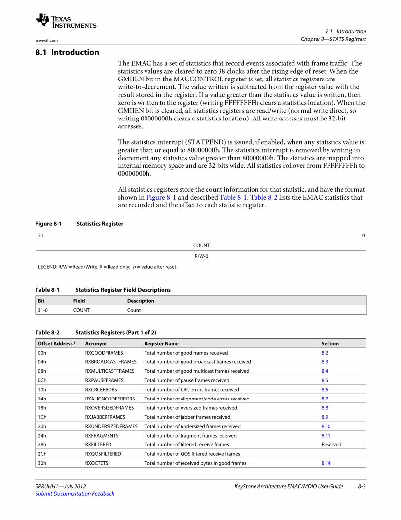
8.1 Introduction
SPRUHH1—July 2012 KeyStone Architecture EMAC/MDIO User Guide 8-3Submit Documentation Feedback
Chapter 8—STATS Registerswww.ti.com
8.1 IntroductionThe EMAC has a set of statistics that record events associated with frame traffic. The statistics values are cleared to zero 38 clocks after the rising edge of reset. When the GMIIEN bit in the MACCONTROL register is set, all statistics registers are write-to-decrement. The value written is subtracted from the register value with the result stored in the register. If a value greater than the statistics value is written, then zero is written to the register (writing FFFFFFFFh clears a statistics location). When the GMIIEN bit is cleared, all statistics registers are read/write (normal write direct, so writing 00000000h clears a statistics location). All write accesses must be 32-bit accesses.
The statistics interrupt (STATPEND) is issued, if enabled, when any statistics value is greater than or equal to 80000000h. The statistics interrupt is removed by writing to decrement any statistics value greater than 80000000h. The statistics are mapped into internal memory space and are 32-bits wide. All statistics rollover from FFFFFFFFh to 00000000h.
All statistics registers store the count information for that statistic, and have the format shown in Figure 8-1 and described Table 8-1. Table 8-2 lists the EMAC statistics that are recorded and the offset to each statistic register.
Figure 8-1 Statistics Register
31 0
COUNT
R/W-0
LEGEND: R/W = Read/Write; R = Read only; -n = value after reset
Table 8-1 Statistics Register Field Descriptions
Bit Field Description
31-0 COUNT Count
Table 8-2 Statistics Registers (Part 1 of 2)
Offset Address 1 Acronym Register Name Section
00h RXGOODFRAMES Total number of good frames received 8.2
04h RXBROADCASTFRAMES Total number of good broadcast frames received 8.3
08h RXMULTICASTFRAMES Total number of good multicast frames received 8.4
0Ch RXPAUSEFRAMES Total number of pause frames received 8.5
10h RXCRCERRORS Total number of CRC errors frames received 8.6
14h RXALIGNCODEERRORS Total number of alignment/code errors received 8.7
18h RXOVERSIZEDFRAMES Total number of oversized frames received 8.8
1Ch RXJABBERFRAMES Total number of jabber frames received 8.9
20h RXUNDERSIZEDFRAMES Total number of undersized frames received 8.10
24h RXFRAGMENTS Total number of fragment frames received 8.11
28h RXFILTERED Total number of filtered receive frames Reserved
2Ch RXQOSFILTERED Total number of QOS filtered receive frames
30h RXOCTETS Total number of received bytes in good frames 8.14
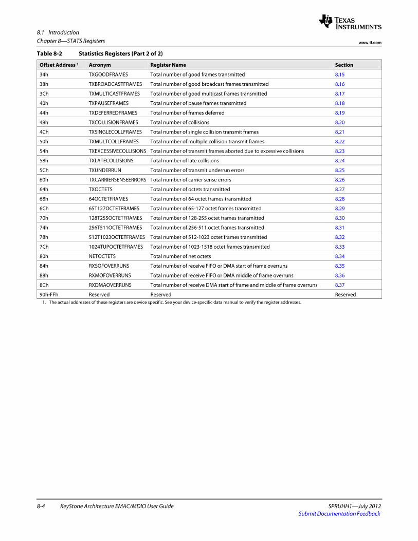
8.1 Introduction
8-4 KeyStone Architecture EMAC/MDIO User Guide SPRUHH1—July 2012Submit Documentation Feedback
Chapter 8—STATS Registers www.ti.com
34h TXGOODFRAMES Total number of good frames transmitted 8.15
38h TXBROADCASTFRAMES Total number of good broadcast frames transmitted 8.16
3Ch TXMULTICASTFRAMES Total number of good multicast frames transmitted 8.17
40h TXPAUSEFRAMES Total number of pause frames transmitted 8.18
44h TXDEFERREDFRAMES Total number of frames deferred 8.19
48h TXCOLLISIONFRAMES Total number of collisions 8.20
4Ch TXSINGLECOLLFRAMES Total number of single collision transmit frames 8.21
50h TXMULTCOLLFRAMES Total number of multiple collision transmit frames 8.22
54h TXEXCESSIVECOLLISIONS Total number of transmit frames aborted due to excessive collisions 8.23
58h TXLATECOLLISIONS Total number of late collisions 8.24
5Ch TXUNDERRUN Total number of transmit underrun errors 8.25
60h TXCARRIERSENSEERRORS Total number of carrier sense errors 8.26
64h TXOCTETS Total number of octets transmitted 8.27
68h 64OCTETFRAMES Total number of 64 octet frames transmitted 8.28
6Ch 65T127OCTETFRAMES Total number of 65-127 octet frames transmitted 8.29
70h 128T255OCTETFRAMES Total number of 128-255 octet frames transmitted 8.30
74h 256T511OCTETFRAMES Total number of 256-511 octet frames transmitted 8.31
78h 512T1023OCTETFRAMES Total number of 512-1023 octet frames transmitted 8.32
7Ch 1024TUPOCTETFRAMES Total number of 1023-1518 octet frames transmitted 8.33
80h NETOCTETS Total number of net octets 8.34
84h RXSOFOVERRUNS Total number of receive FIFO or DMA start of frame overruns 8.35
88h RXMOFOVERRUNS Total number of receive FIFO or DMA middle of frame overruns 8.36
8Ch RXDMAOVERRUNS Total number of receive DMA start of frame and middle of frame overruns 8.37
90h-FFh Reserved Reserved Reserved1. The actual addresses of these registers are device specific. See your device-specific data manual to verify the register addresses.
Table 8-2 Statistics Registers (Part 2 of 2)
Offset Address 1 Acronym Register Name Section
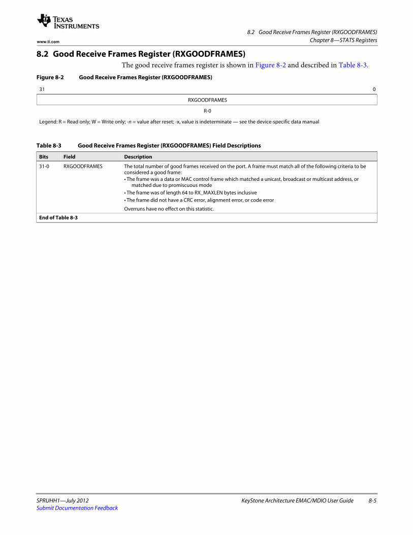
8.2 Good Receive Frames Register (RXGOODFRAMES)
SPRUHH1—July 2012 KeyStone Architecture EMAC/MDIO User Guide 8-5Submit Documentation Feedback
Chapter 8—STATS Registerswww.ti.com
8.2 Good Receive Frames Register (RXGOODFRAMES)The good receive frames register is shown in Figure 8-2 and described in Table 8-3.
Figure 8-2 Good Receive Frames Register (RXGOODFRAMES)
31 0
RXGOODFRAMES
R-0
Legend: R = Read only; W = Write only; -n = value after reset; -x, value is indeterminate — see the device-specific data manual
Table 8-3 Good Receive Frames Register (RXGOODFRAMES) Field Descriptions
Bits Field Description
31-0 RXGOODFRAMES The total number of good frames received on the port. A frame must match all of the following criteria to be considered a good frame:• The frame was a data or MAC control frame which matched a unicast, broadcast or multicast address, or
matched due to promiscuous mode• The frame was of length 64 to RX_MAXLEN bytes inclusive• The frame did not have a CRC error, alignment error, or code error
Overruns have no effect on this statistic.
End of Table 8-3
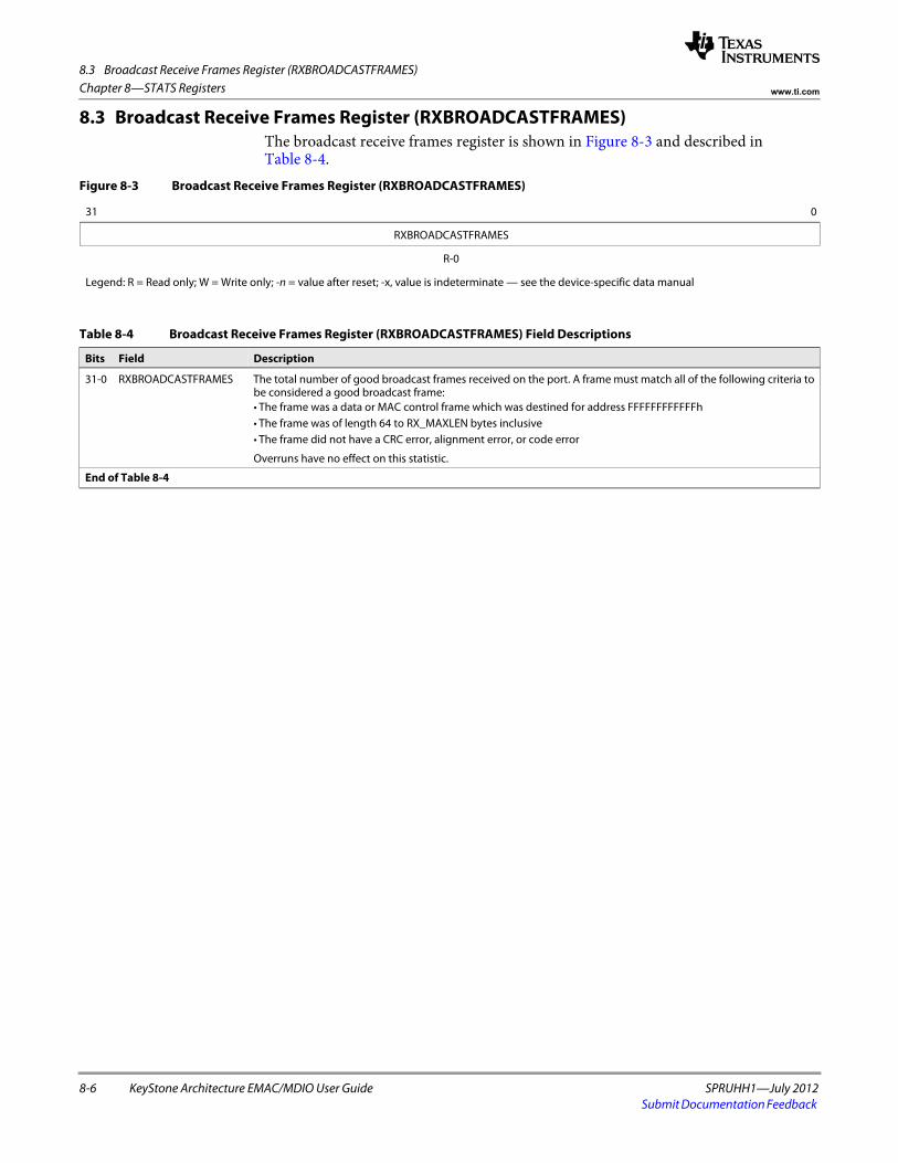
8.3 Broadcast Receive Frames Register (RXBROADCASTFRAMES)
8-6 KeyStone Architecture EMAC/MDIO User Guide SPRUHH1—July 2012Submit Documentation Feedback
Chapter 8—STATS Registers www.ti.com
8.3 Broadcast Receive Frames Register (RXBROADCASTFRAMES)The broadcast receive frames register is shown in Figure 8-3 and described in Table 8-4.
Figure 8-3 Broadcast Receive Frames Register (RXBROADCASTFRAMES)
31 0
RXBROADCASTFRAMES
R-0
Legend: R = Read only; W = Write only; -n = value after reset; -x, value is indeterminate — see the device-specific data manual
Table 8-4 Broadcast Receive Frames Register (RXBROADCASTFRAMES) Field Descriptions
Bits Field Description
31-0 RXBROADCASTFRAMES The total number of good broadcast frames received on the port. A frame must match all of the following criteria to be considered a good broadcast frame:• The frame was a data or MAC control frame which was destined for address FFFFFFFFFFFFh • The frame was of length 64 to RX_MAXLEN bytes inclusive• The frame did not have a CRC error, alignment error, or code error
Overruns have no effect on this statistic.
End of Table 8-4
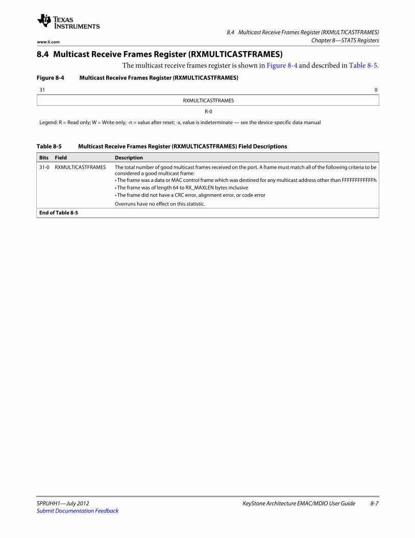
8.4 Multicast Receive Frames Register (RXMULTICASTFRAMES)
SPRUHH1—July 2012 KeyStone Architecture EMAC/MDIO User Guide 8-7Submit Documentation Feedback
Chapter 8—STATS Registerswww.ti.com
8.4 Multicast Receive Frames Register (RXMULTICASTFRAMES)The multicast receive frames register is shown in Figure 8-4 and described in Table 8-5.
Figure 8-4 Multicast Receive Frames Register (RXMULTICASTFRAMES)
31 0
RXMULTICASTFRAMES
R-0
Legend: R = Read only; W = Write only; -n = value after reset; -x, value is indeterminate — see the device-specific data manual
Table 8-5 Multicast Receive Frames Register (RXMULTICASTFRAMES) Field Descriptions
Bits Field Description
31-0 RXMULTICASTFRAMES The total number of good multicast frames received on the port. A frame must match all of the following criteria to be considered a good multicast frame:• The frame was a data or MAC control frame which was destined for any multicast address other than FFFFFFFFFFFFh • The frame was of length 64 to RX_MAXLEN bytes inclusive• The frame did not have a CRC error, alignment error, or code error
Overruns have no effect on this statistic.
End of Table 8-5
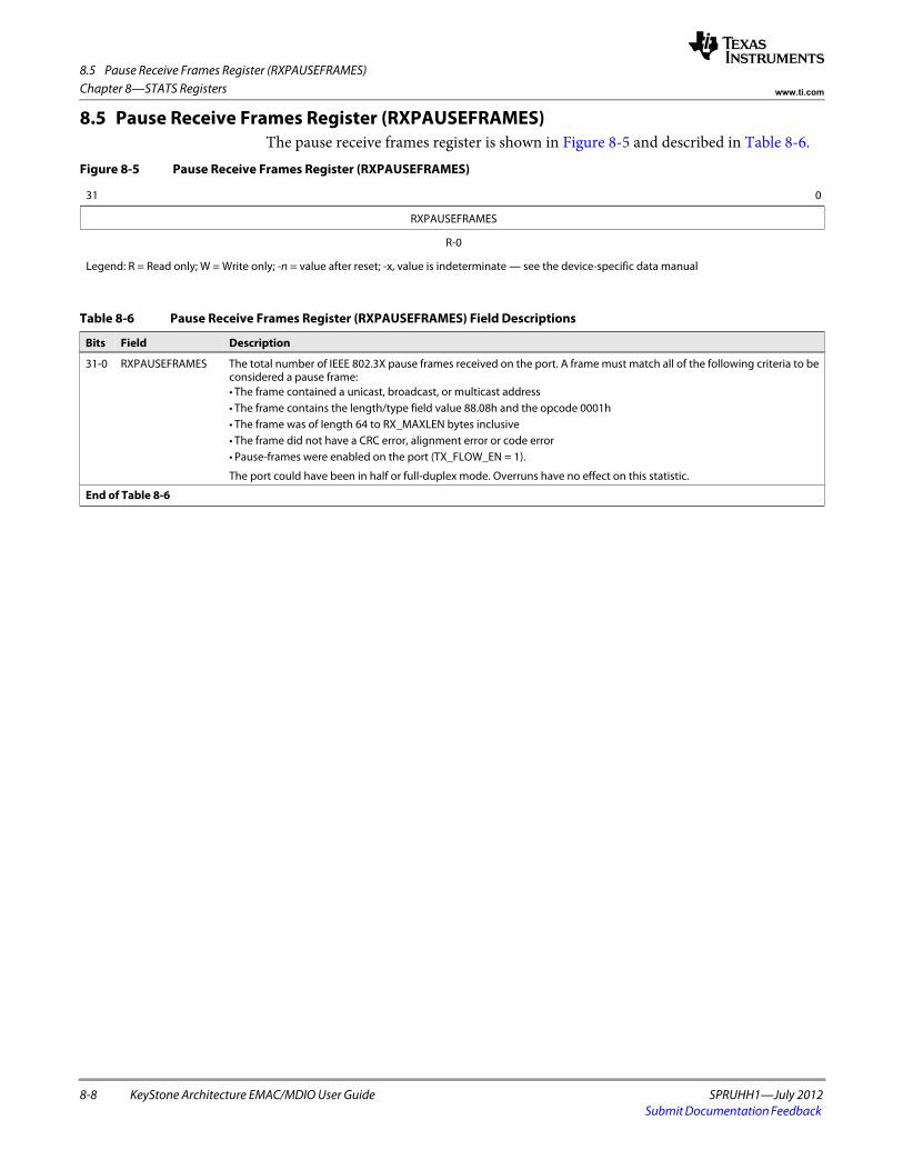
8.5 Pause Receive Frames Register (RXPAUSEFRAMES)
8-8 KeyStone Architecture EMAC/MDIO User Guide SPRUHH1—July 2012Submit Documentation Feedback
Chapter 8—STATS Registers www.ti.com
8.5 Pause Receive Frames Register (RXPAUSEFRAMES)The pause receive frames register is shown in Figure 8-5 and described in Table 8-6.
Figure 8-5 Pause Receive Frames Register (RXPAUSEFRAMES)
31 0
RXPAUSEFRAMES
R-0
Legend: R = Read only; W = Write only; -n = value after reset; -x, value is indeterminate — see the device-specific data manual
Table 8-6 Pause Receive Frames Register (RXPAUSEFRAMES) Field Descriptions
Bits Field Description
31-0 RXPAUSEFRAMES The total number of IEEE 802.3X pause frames received on the port. A frame must match all of the following criteria to be considered a pause frame:• The frame contained a unicast, broadcast, or multicast address• The frame contains the length/type field value 88.08h and the opcode 0001h• The frame was of length 64 to RX_MAXLEN bytes inclusive• The frame did not have a CRC error, alignment error or code error• Pause-frames were enabled on the port (TX_FLOW_EN = 1).
The port could have been in half or full-duplex mode. Overruns have no effect on this statistic.
End of Table 8-6
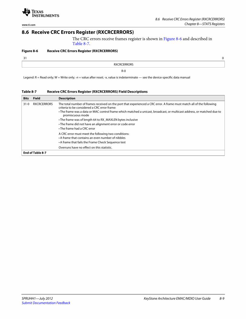
8.6 Receive CRC Errors Register (RXCRCERRORS)
SPRUHH1—July 2012 KeyStone Architecture EMAC/MDIO User Guide 8-9Submit Documentation Feedback
Chapter 8—STATS Registerswww.ti.com
8.6 Receive CRC Errors Register (RXCRCERRORS)The CRC errors receive frames register is shown in Figure 8-6 and described in Table 8-7.
Figure 8-6 Receive CRC Errors Register (RXCRCERRORS)
31 0
RXCRCERRORS
R-0
Legend: R = Read only; W = Write only; -n = value after reset; -x, value is indeterminate — see the device-specific data manual
Table 8-7 Receive CRC Errors Register (RXCRCERRORS) Field Descriptions
Bits Field Description
31-0 RXCRCERRORS The total number of frames received on the port that experienced a CRC error. A frame must match all of the following criteria to be considered a CRC error frame:• The frame was a data or MAC control frame which matched a unicast, broadcast, or multicast address, or matched due to
promiscuous mode• The frame was of length 64 to RX_MAXLEN bytes inclusive• The frame did not have an alignment error or code error• The frame had a CRC error
A CRC error must meet the following two conditions:• A frame that contains an even number of nibbles• A frame that fails the Frame Check Sequence test
Overruns have no effect on this statistic.
End of Table 8-7
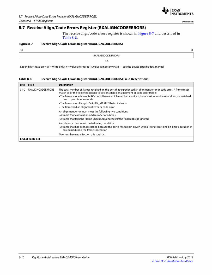
8.7 Receive Align/Code Errors Register (RXALIGNCODEERRORS)
8-10 KeyStone Architecture EMAC/MDIO User Guide SPRUHH1—July 2012Submit Documentation Feedback
Chapter 8—STATS Registers www.ti.com
8.7 Receive Align/Code Errors Register (RXALIGNCODEERRORS)The receive align/code errors register is shown in Figure 8-7 and described in Table 8-8.
Figure 8-7 Receive Align/Code Errors Register (RXALIGNCODEERRORS)
31 0
RXALIGNCODEERRORS
R-0
Legend: R = Read only; W = Write only; -n = value after reset; -x, value is indeterminate — see the device-specific data manual
Table 8-8 Receive Align/Code Errors Register (RXALIGNCODEERRORS) Field Descriptions
Bits Field Description
31-0 RXALIGNCODEERRORS The total number of frames received on the port that experienced an alignment error or code error. A frame must match all of the following criteria to be considered an alignment or code error frame:• The frame was a data or MAC control frame which matched a unicast, broadcast, or multicast address, or matched
due to promiscuous mode• The frame was of length 64 to RX_MAXLEN bytes inclusive• The frame had an alignment error or code error
An alignment error must meet the following two conditions:• A frame that contains an odd number of nibbles• A frame that fails the Frame Check Sequence test if the final nibble is ignored
A code error must meet the following condition:• A frame that has been discarded because the port’s MRXER pin driven with a 1 for at least one bit-time’s duration at
any point during the frame’s reception
Overruns have no effect on this statistic.
End of Table 8-8
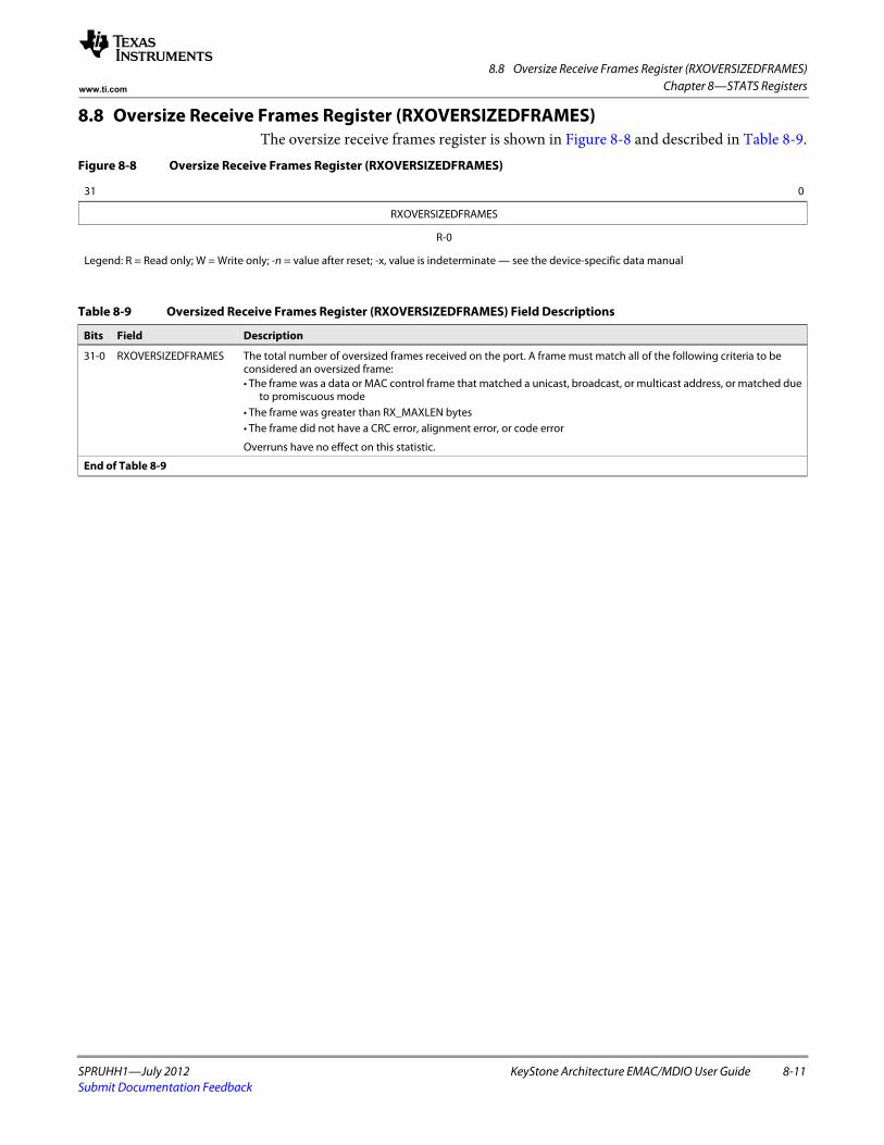
8.8 Oversize Receive Frames Register (RXOVERSIZEDFRAMES)
SPRUHH1—July 2012 KeyStone Architecture EMAC/MDIO User Guide 8-11Submit Documentation Feedback
Chapter 8—STATS Registerswww.ti.com
8.8 Oversize Receive Frames Register (RXOVERSIZEDFRAMES)The oversize receive frames register is shown in Figure 8-8 and described in Table 8-9.
Figure 8-8 Oversize Receive Frames Register (RXOVERSIZEDFRAMES)
31 0
RXOVERSIZEDFRAMES
R-0
Legend: R = Read only; W = Write only; -n = value after reset; -x, value is indeterminate — see the device-specific data manual
Table 8-9 Oversized Receive Frames Register (RXOVERSIZEDFRAMES) Field Descriptions
Bits Field Description
31-0 RXOVERSIZEDFRAMES The total number of oversized frames received on the port. A frame must match all of the following criteria to be considered an oversized frame:• The frame was a data or MAC control frame that matched a unicast, broadcast, or multicast address, or matched due
to promiscuous mode• The frame was greater than RX_MAXLEN bytes• The frame did not have a CRC error, alignment error, or code error
Overruns have no effect on this statistic.
End of Table 8-9
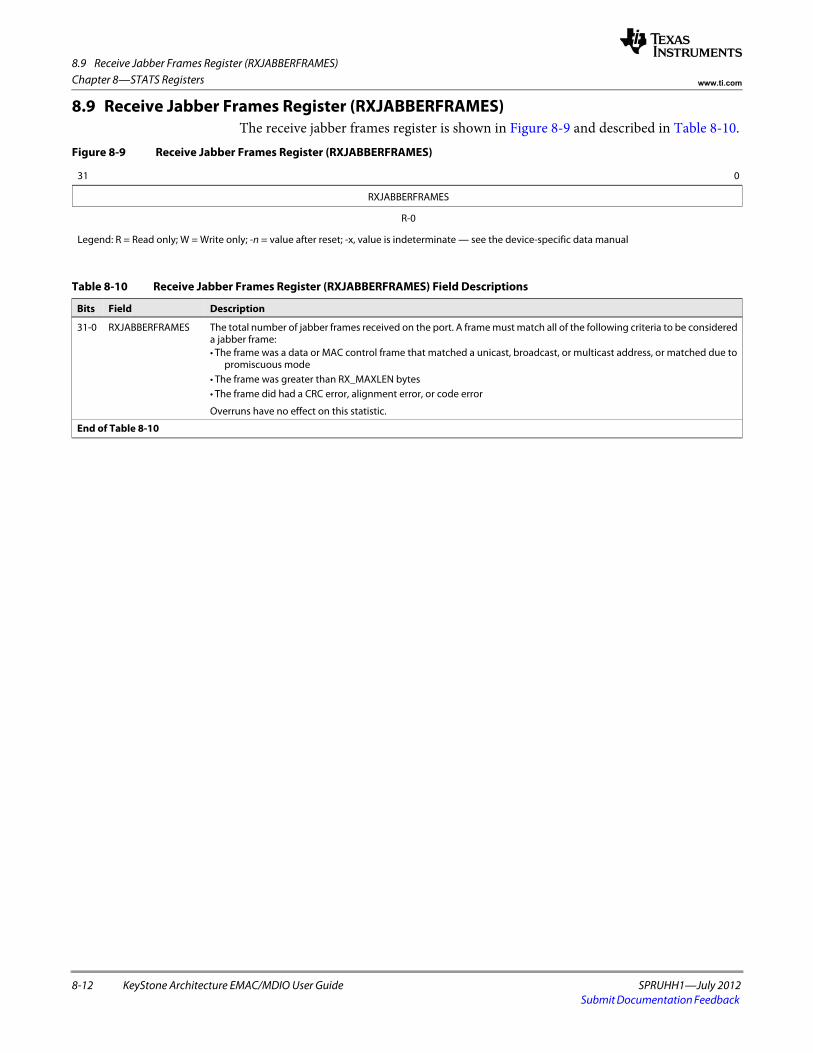
8.9 Receive Jabber Frames Register (RXJABBERFRAMES)
8-12 KeyStone Architecture EMAC/MDIO User Guide SPRUHH1—July 2012Submit Documentation Feedback
Chapter 8—STATS Registers www.ti.com
8.9 Receive Jabber Frames Register (RXJABBERFRAMES)The receive jabber frames register is shown in Figure 8-9 and described in Table 8-10.
Figure 8-9 Receive Jabber Frames Register (RXJABBERFRAMES)
31 0
RXJABBERFRAMES
R-0
Legend: R = Read only; W = Write only; -n = value after reset; -x, value is indeterminate — see the device-specific data manual
Table 8-10 Receive Jabber Frames Register (RXJABBERFRAMES) Field Descriptions
Bits Field Description
31-0 RXJABBERFRAMES The total number of jabber frames received on the port. A frame must match all of the following criteria to be considered a jabber frame:• The frame was a data or MAC control frame that matched a unicast, broadcast, or multicast address, or matched due to
promiscuous mode• The frame was greater than RX_MAXLEN bytes• The frame did had a CRC error, alignment error, or code error
Overruns have no effect on this statistic.
End of Table 8-10
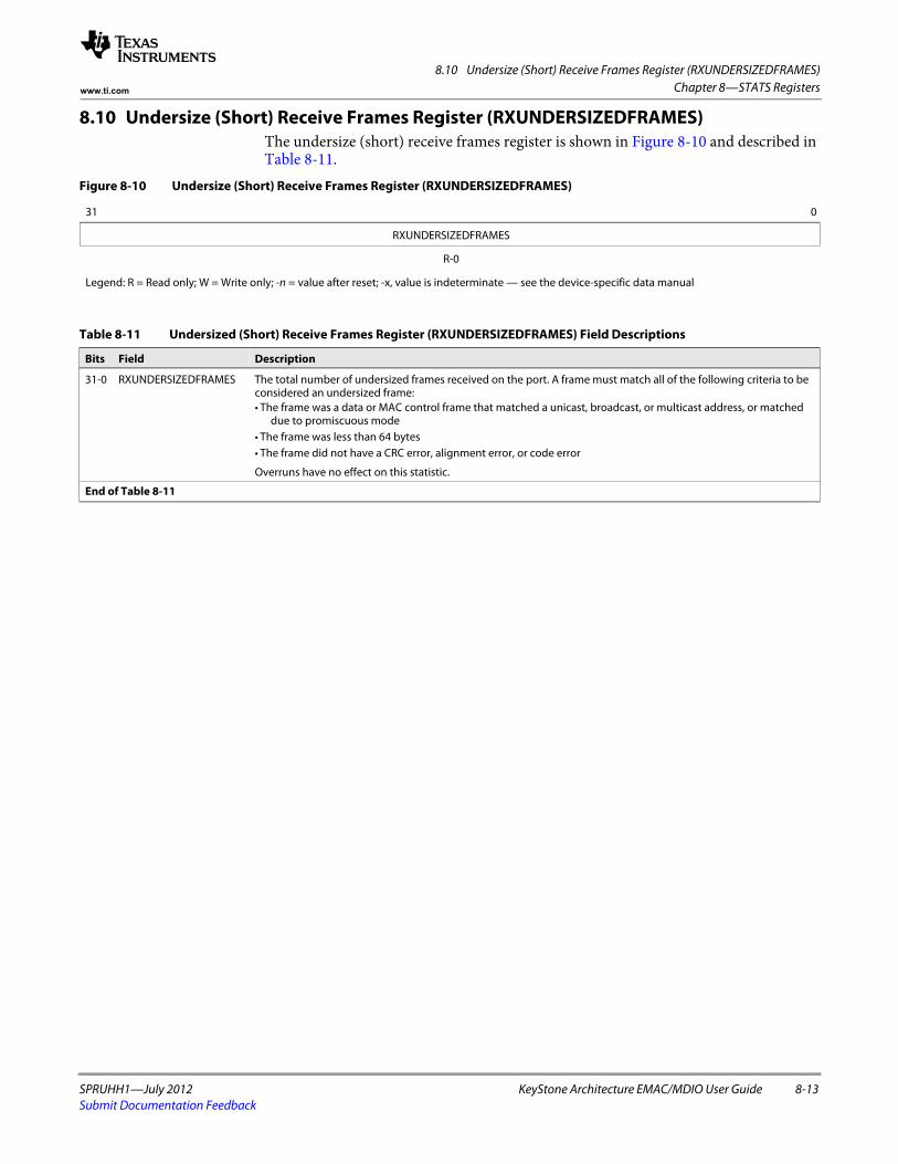
8.10 Undersize (Short) Receive Frames Register (RXUNDERSIZEDFRAMES)
SPRUHH1—July 2012 KeyStone Architecture EMAC/MDIO User Guide 8-13Submit Documentation Feedback
Chapter 8—STATS Registerswww.ti.com
8.10 Undersize (Short) Receive Frames Register (RXUNDERSIZEDFRAMES)The undersize (short) receive frames register is shown in Figure 8-10 and described in Table 8-11.
Figure 8-10 Undersize (Short) Receive Frames Register (RXUNDERSIZEDFRAMES)
31 0
RXUNDERSIZEDFRAMES
R-0
Legend: R = Read only; W = Write only; -n = value after reset; -x, value is indeterminate — see the device-specific data manual
Table 8-11 Undersized (Short) Receive Frames Register (RXUNDERSIZEDFRAMES) Field Descriptions
Bits Field Description
31-0 RXUNDERSIZEDFRAMES The total number of undersized frames received on the port. A frame must match all of the following criteria to be considered an undersized frame:• The frame was a data or MAC control frame that matched a unicast, broadcast, or multicast address, or matched
due to promiscuous mode• The frame was less than 64 bytes• The frame did not have a CRC error, alignment error, or code error
Overruns have no effect on this statistic.
End of Table 8-11
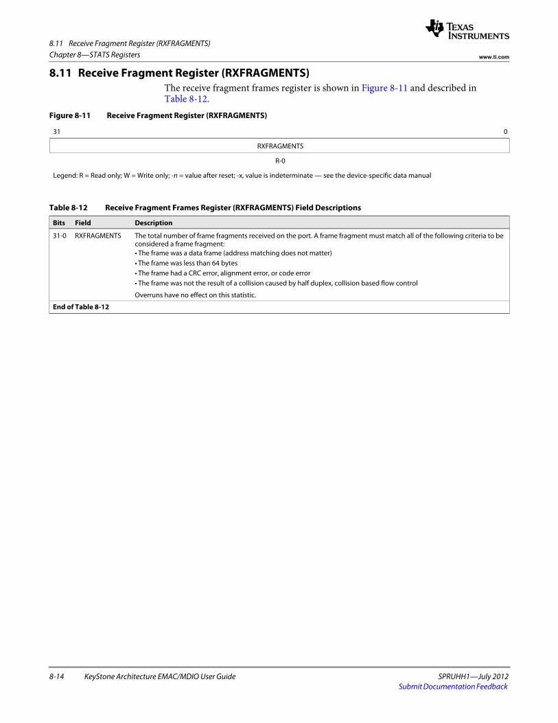
8.11 Receive Fragment Register (RXFRAGMENTS)
8-14 KeyStone Architecture EMAC/MDIO User Guide SPRUHH1—July 2012Submit Documentation Feedback
Chapter 8—STATS Registers www.ti.com
8.11 Receive Fragment Register (RXFRAGMENTS)The receive fragment frames register is shown in Figure 8-11 and described in Table 8-12.
Figure 8-11 Receive Fragment Register (RXFRAGMENTS)
31 0
RXFRAGMENTS
R-0
Legend: R = Read only; W = Write only; -n = value after reset; -x, value is indeterminate — see the device-specific data manual
Table 8-12 Receive Fragment Frames Register (RXFRAGMENTS) Field Descriptions
Bits Field Description
31-0 RXFRAGMENTS The total number of frame fragments received on the port. A frame fragment must match all of the following criteria to be considered a frame fragment:• The frame was a data frame (address matching does not matter)• The frame was less than 64 bytes• The frame had a CRC error, alignment error, or code error• The frame was not the result of a collision caused by half duplex, collision based flow control
Overruns have no effect on this statistic.
End of Table 8-12
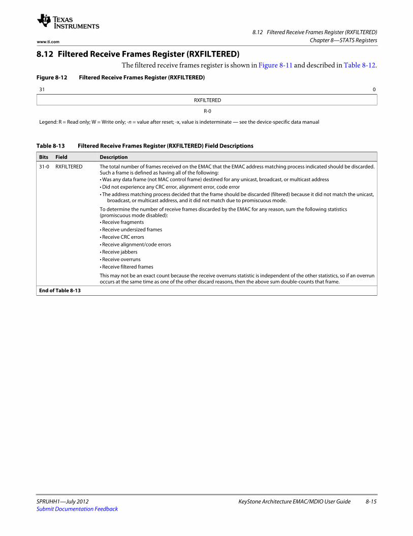
8.12 Filtered Receive Frames Register (RXFILTERED)
SPRUHH1—July 2012 KeyStone Architecture EMAC/MDIO User Guide 8-15Submit Documentation Feedback
Chapter 8—STATS Registerswww.ti.com
8.12 Filtered Receive Frames Register (RXFILTERED)The filtered receive frames register is shown in Figure 8-11 and described in Table 8-12.
Figure 8-12 Filtered Receive Frames Register (RXFILTERED)
31 0
RXFILTERED
R-0
Legend: R = Read only; W = Write only; -n = value after reset; -x, value is indeterminate — see the device-specific data manual
Table 8-13 Filtered Receive Frames Register (RXFILTERED) Field Descriptions
Bits Field Description
31-0 RXFILTERED The total number of frames received on the EMAC that the EMAC address matching process indicated should be discarded. Such a frame is defined as having all of the following:• Was any data frame (not MAC control frame) destined for any unicast, broadcast, or multicast address• Did not experience any CRC error, alignment error, code error• The address matching process decided that the frame should be discarded (filtered) because it did not match the unicast,
broadcast, or multicast address, and it did not match due to promiscuous mode.
To determine the number of receive frames discarded by the EMAC for any reason, sum the following statistics (promiscuous mode disabled):• Receive fragments• Receive undersized frames• Receive CRC errors• Receive alignment/code errors• Receive jabbers• Receive overruns• Receive filtered frames
This may not be an exact count because the receive overruns statistic is independent of the other statistics, so if an overrun occurs at the same time as one of the other discard reasons, then the above sum double-counts that frame.
End of Table 8-13
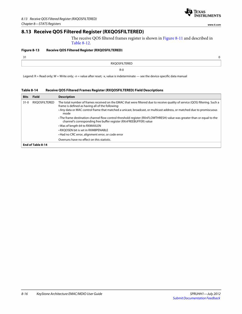
8.13 Receive QOS Filtered Register (RXQOSFILTERED)
8-16 KeyStone Architecture EMAC/MDIO User Guide SPRUHH1—July 2012Submit Documentation Feedback
Chapter 8—STATS Registers www.ti.com
8.13 Receive QOS Filtered Register (RXQOSFILTERED)The receive QOS filtered frames register is shown in Figure 8-11 and described in Table 8-12.
Figure 8-13 Receive QOS Filtered Register (RXQOSFILTERED)
31 0
RXQOSFILTERED
R-0
Legend: R = Read only; W = Write only; -n = value after reset; -x, value is indeterminate — see the device-specific data manual
Table 8-14 Receive QOS Filtered Frames Register (RXQOSFILTERED) Field Descriptions
Bits Field Description
31-0 RXQOSFILTERED The total number of frames received on the EMAC that were filtered due to receive quality of service (QOS) filtering. Such a frame is defined as having all of the following:• Any data or MAC control frame that matched a unicast, broadcast, or multicast address, or matched due to promiscuous
mode• The frame destination channel flow control threshold register (RXnFLOWTHRESH) value was greater than or equal to the
channel's corresponding free buffer register (RXnFREEBUFFER) value• Was of length 64 to RXMAXLEN• RXQOSEN bit is set in RXMBPENABLE• Had no CRC error, alignment error, or code error
Overruns have no effect on this statistic.
End of Table 8-14
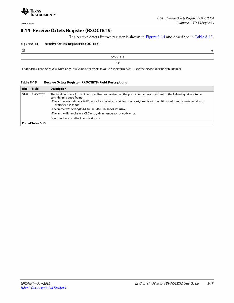
8.14 Receive Octets Register (RXOCTETS)
SPRUHH1—July 2012 KeyStone Architecture EMAC/MDIO User Guide 8-17Submit Documentation Feedback
Chapter 8—STATS Registerswww.ti.com
8.14 Receive Octets Register (RXOCTETS)The receive octets frames register is shown in Figure 8-14 and described in Table 8-15.
Figure 8-14 Receive Octets Register (RXOCTETS)
31 0
RXOCTETS
R-0
Legend: R = Read only; W = Write only; -n = value after reset; -x, value is indeterminate — see the device-specific data manual
Table 8-15 Receive Octets Register (RXOCTETS) Field Descriptions
Bits Field Description
31-0 RXOCTETS The total number of bytes in all good frames received on the port. A frame must match all of the following criteria to be considered a good frame:• The frame was a data or MAC control frame which matched a unicast, broadcast or multicast address, or matched due to
promiscuous mode• The frame was of length 64 to RX_MAXLEN bytes inclusive• The frame did not have a CRC error, alignment error, or code error
Overruns have no effect on this statistic.
End of Table 8-15
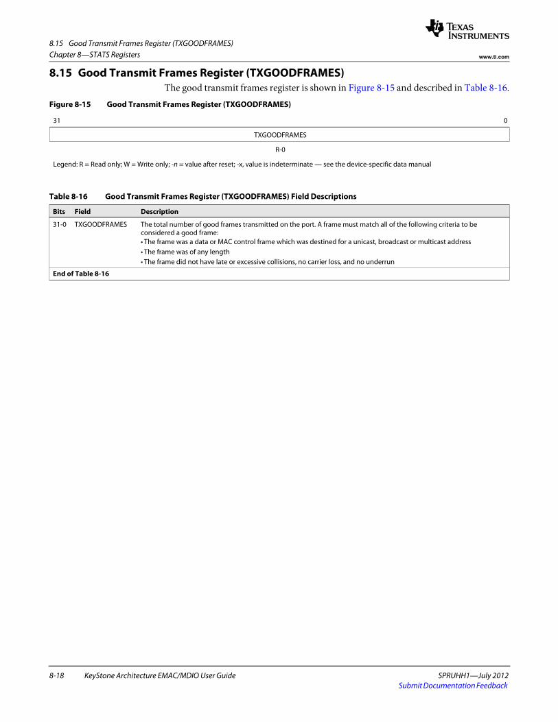
8.15 Good Transmit Frames Register (TXGOODFRAMES)
8-18 KeyStone Architecture EMAC/MDIO User Guide SPRUHH1—July 2012Submit Documentation Feedback
Chapter 8—STATS Registers www.ti.com
8.15 Good Transmit Frames Register (TXGOODFRAMES)The good transmit frames register is shown in Figure 8-15 and described in Table 8-16.
Figure 8-15 Good Transmit Frames Register (TXGOODFRAMES)
31 0
TXGOODFRAMES
R-0
Legend: R = Read only; W = Write only; -n = value after reset; -x, value is indeterminate — see the device-specific data manual
Table 8-16 Good Transmit Frames Register (TXGOODFRAMES) Field Descriptions
Bits Field Description
31-0 TXGOODFRAMES The total number of good frames transmitted on the port. A frame must match all of the following criteria to be considered a good frame:• The frame was a data or MAC control frame which was destined for a unicast, broadcast or multicast address• The frame was of any length• The frame did not have late or excessive collisions, no carrier loss, and no underrun
End of Table 8-16
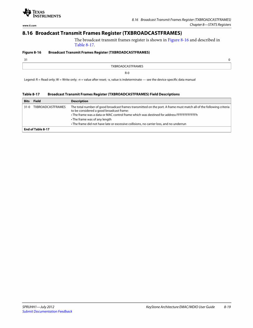
8.16 Broadcast Transmit Frames Register (TXBROADCASTFRAMES)
SPRUHH1—July 2012 KeyStone Architecture EMAC/MDIO User Guide 8-19Submit Documentation Feedback
Chapter 8—STATS Registerswww.ti.com
8.16 Broadcast Transmit Frames Register (TXBROADCASTFRAMES)The broadcast transmit frames register is shown in Figure 8-16 and described in Table 8-17.
Figure 8-16 Broadcast Transmit Frames Register (TXBROADCASTFRAMES)
31 0
TXBROADCASTFRAMES
R-0
Legend: R = Read only; W = Write only; -n = value after reset; -x, value is indeterminate — see the device-specific data manual
Table 8-17 Broadcast Transmit Frames Register (TXBROADCASTFRAMES) Field Descriptions
Bits Field Description
31-0 TXBROADCASTFRAMES The total number of good broadcast frames transmitted on the port. A frame must match all of the following criteria to be considered a good broadcast frame:• The frame was a data or MAC control frame which was destined for address FFFFFFFFFFFFh• The frame was of any length• The frame did not have late or excessive collisions, no carrier loss, and no underrun
End of Table 8-17
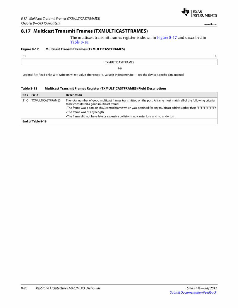
8.17 Multicast Transmit Frames (TXMULTICASTFRAMES)
8-20 KeyStone Architecture EMAC/MDIO User Guide SPRUHH1—July 2012Submit Documentation Feedback
Chapter 8—STATS Registers www.ti.com
8.17 Multicast Transmit Frames (TXMULTICASTFRAMES)The multicast transmit frames register is shown in Figure 8-17 and described in Table 8-18.
Figure 8-17 Multicast Transmit Frames (TXMULTICASTFRAMES)
31 0
TXMULTICASTFRAMES
R-0
Legend: R = Read only; W = Write only; -n = value after reset; -x, value is indeterminate — see the device-specific data manual
Table 8-18 Multicast Transmit Frames Register (TXMULTICASTFRAMES) Field Descriptions
Bits Field Description
31-0 TXMULTICASTFRAMES The total number of good multicast frames transmitted on the port. A frame must match all of the following criteria to be considered a good multicast frame:• The frame was a data or MAC control frame which was destined for any multicast address other than FFFFFFFFFFFFh• The frame was of any length• The frame did not have late or excessive collisions, no carrier loss, and no underrun
End of Table 8-18
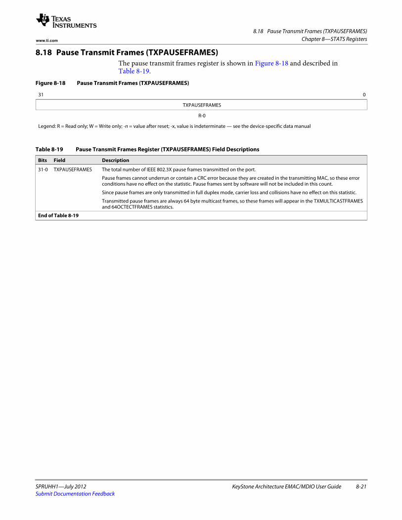
8.18 Pause Transmit Frames (TXPAUSEFRAMES)
SPRUHH1—July 2012 KeyStone Architecture EMAC/MDIO User Guide 8-21Submit Documentation Feedback
Chapter 8—STATS Registerswww.ti.com
8.18 Pause Transmit Frames (TXPAUSEFRAMES)The pause transmit frames register is shown in Figure 8-18 and described in Table 8-19.
Figure 8-18 Pause Transmit Frames (TXPAUSEFRAMES)
31 0
TXPAUSEFRAMES
R-0
Legend: R = Read only; W = Write only; -n = value after reset; -x, value is indeterminate — see the device-specific data manual
Table 8-19 Pause Transmit Frames Register (TXPAUSEFRAMES) Field Descriptions
Bits Field Description
31-0 TXPAUSEFRAMES The total number of IEEE 802.3X pause frames transmitted on the port.
Pause frames cannot underrun or contain a CRC error because they are created in the transmitting MAC, so these error conditions have no effect on the statistic. Pause frames sent by software will not be included in this count.
Since pause frames are only transmitted in full duplex mode, carrier loss and collisions have no effect on this statistic.
Transmitted pause frames are always 64 byte multicast frames, so these frames will appear in the TXMULTICASTFRAMES and 64OCTECTFRAMES statistics.
End of Table 8-19
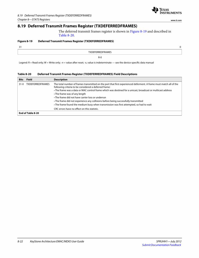
8.19 Deferred Transmit Frames Register (TXDEFERREDFRAMES)
8-22 KeyStone Architecture EMAC/MDIO User Guide SPRUHH1—July 2012Submit Documentation Feedback
Chapter 8—STATS Registers www.ti.com
8.19 Deferred Transmit Frames Register (TXDEFERREDFRAMES)The deferred transmit frames register is shown in Figure 8-19 and described in Table 8-20.
Figure 8-19 Deferred Transmit Frames Register (TXDEFERREDFRAMES)
31 0
TXDEFERREDFRAMES
R-0
Legend: R = Read only; W = Write only; -n = value after reset; -x, value is indeterminate — see the device-specific data manual
Table 8-20 Deferred Transmit Frames Register (TXDEFERREDFRAMES) Field Descriptions
Bits Field Description
31-0 TXDEFERREDFRAMES The total number of frames transmitted on the port that first experienced deferment. A frame must match all of the following criteria to be considered a deferred frame:• The frame was a data or MAC control frame which was destined for a unicast, broadcast or multicast address• The frame was of any length• The frame did not have carrier loss or underrun• The frame did not experience any collisions before being successfully transmitted• The frame found the medium busy when transmission was first attempted, so had to wait
CRC errors have no effect on this statistic.
End of Table 8-20
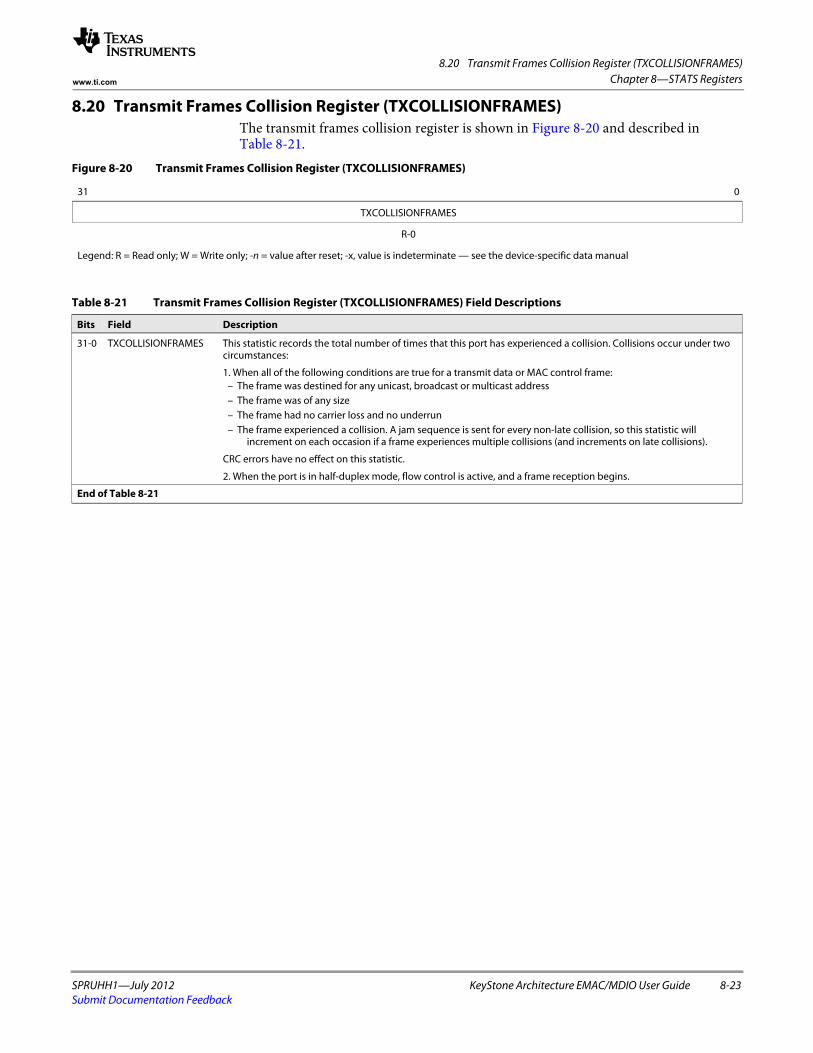
8.20 Transmit Frames Collision Register (TXCOLLISIONFRAMES)
SPRUHH1—July 2012 KeyStone Architecture EMAC/MDIO User Guide 8-23Submit Documentation Feedback
Chapter 8—STATS Registerswww.ti.com
8.20 Transmit Frames Collision Register (TXCOLLISIONFRAMES)The transmit frames collision register is shown in Figure 8-20 and described in Table 8-21.
Figure 8-20 Transmit Frames Collision Register (TXCOLLISIONFRAMES)
31 0
TXCOLLISIONFRAMES
R-0
Legend: R = Read only; W = Write only; -n = value after reset; -x, value is indeterminate — see the device-specific data manual
Table 8-21 Transmit Frames Collision Register (TXCOLLISIONFRAMES) Field Descriptions
Bits Field Description
31-0 TXCOLLISIONFRAMES This statistic records the total number of times that this port has experienced a collision. Collisions occur under two circumstances:
1. When all of the following conditions are true for a transmit data or MAC control frame:– The frame was destined for any unicast, broadcast or multicast address– The frame was of any size– The frame had no carrier loss and no underrun– The frame experienced a collision. A jam sequence is sent for every non-late collision, so this statistic will
increment on each occasion if a frame experiences multiple collisions (and increments on late collisions).
CRC errors have no effect on this statistic.
2. When the port is in half-duplex mode, flow control is active, and a frame reception begins.
End of Table 8-21
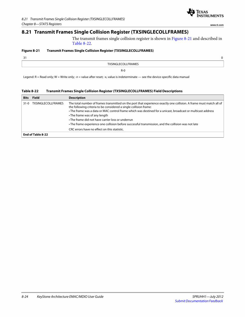
8.21 Transmit Frames Single Collision Register (TXSINGLECOLLFRAMES)
8-24 KeyStone Architecture EMAC/MDIO User Guide SPRUHH1—July 2012Submit Documentation Feedback
Chapter 8—STATS Registers www.ti.com
8.21 Transmit Frames Single Collision Register (TXSINGLECOLLFRAMES)The transmit frames single collision register is shown in Figure 8-21 and described in Table 8-22.
Figure 8-21 Transmit Frames Single Collision Register (TXSINGLECOLLFRAMES)
31 0
TXSINGLECOLLFRAMES
R-0
Legend: R = Read only; W = Write only; -n = value after reset; -x, value is indeterminate — see the device-specific data manual
Table 8-22 Transmit Frames Single Collision Register (TXSINGLECOLLFRAMES) Field Descriptions
Bits Field Description
31-0 TXSINGLECOLLFRAMES The total number of frames transmitted on the port that experience exactly one collision. A frame must match all of the following criteria to be considered a single collision frame:• The frame was a data or MAC control frame which was destined for a unicast, broadcast or multicast address• The frame was of any length• The frame did not have carrier loss or underrun• The frame experience one collision before successful transmission, and the collision was not late
CRC errors have no effect on this statistic.
End of Table 8-22
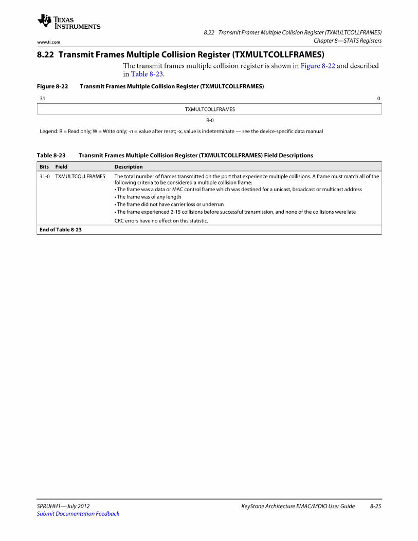
8.22 Transmit Frames Multiple Collision Register (TXMULTCOLLFRAMES)
SPRUHH1—July 2012 KeyStone Architecture EMAC/MDIO User Guide 8-25Submit Documentation Feedback
Chapter 8—STATS Registerswww.ti.com
8.22 Transmit Frames Multiple Collision Register (TXMULTCOLLFRAMES)The transmit frames multiple collision register is shown in Figure 8-22 and described in Table 8-23.
Figure 8-22 Transmit Frames Multiple Collision Register (TXMULTCOLLFRAMES)
31 0
TXMULTCOLLFRAMES
R-0
Legend: R = Read only; W = Write only; -n = value after reset; -x, value is indeterminate — see the device-specific data manual
Table 8-23 Transmit Frames Multiple Collision Register (TXMULTCOLLFRAMES) Field Descriptions
Bits Field Description
31-0 TXMULTCOLLFRAMES The total number of frames transmitted on the port that experience multiple collisions. A frame must match all of the following criteria to be considered a multiple collision frame:• The frame was a data or MAC control frame which was destined for a unicast, broadcast or multicast address• The frame was of any length• The frame did not have carrier loss or underrun• The frame experienced 2-15 collisions before successful transmission, and none of the collisions were late
CRC errors have no effect on this statistic.
End of Table 8-23
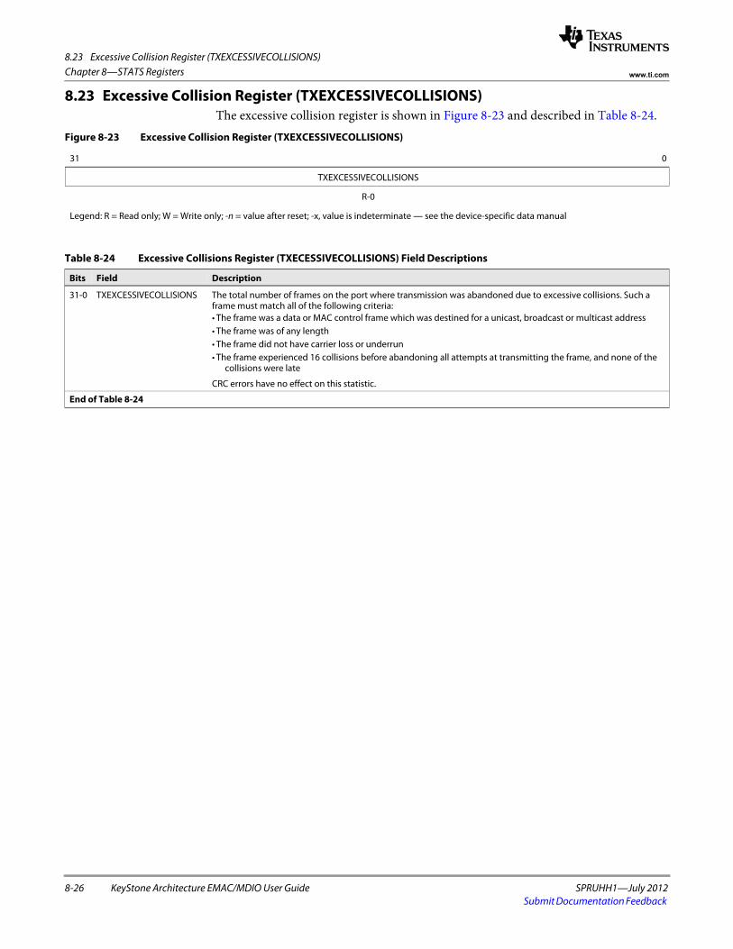
8.23 Excessive Collision Register (TXEXCESSIVECOLLISIONS)
8-26 KeyStone Architecture EMAC/MDIO User Guide SPRUHH1—July 2012Submit Documentation Feedback
Chapter 8—STATS Registers www.ti.com
8.23 Excessive Collision Register (TXEXCESSIVECOLLISIONS)The excessive collision register is shown in Figure 8-23 and described in Table 8-24.
Figure 8-23 Excessive Collision Register (TXEXCESSIVECOLLISIONS)
31 0
TXEXCESSIVECOLLISIONS
R-0
Legend: R = Read only; W = Write only; -n = value after reset; -x, value is indeterminate — see the device-specific data manual
Table 8-24 Excessive Collisions Register (TXECESSIVECOLLISIONS) Field Descriptions
Bits Field Description
31-0 TXEXCESSIVECOLLISIONS The total number of frames on the port where transmission was abandoned due to excessive collisions. Such a frame must match all of the following criteria:• The frame was a data or MAC control frame which was destined for a unicast, broadcast or multicast address• The frame was of any length• The frame did not have carrier loss or underrun• The frame experienced 16 collisions before abandoning all attempts at transmitting the frame, and none of the
collisions were late
CRC errors have no effect on this statistic.
End of Table 8-24
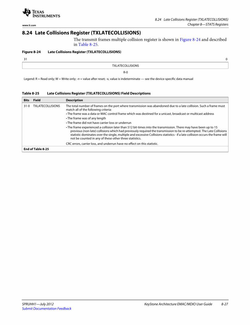
8.24 Late Collisions Register (TXLATECOLLISIONS)
SPRUHH1—July 2012 KeyStone Architecture EMAC/MDIO User Guide 8-27Submit Documentation Feedback
Chapter 8—STATS Registerswww.ti.com
8.24 Late Collisions Register (TXLATECOLLISIONS)The transmit frames multiple collision register is shown in Figure 8-24 and described in Table 8-25.
Figure 8-24 Late Collisions Register (TXLATECOLLISIONS)
31 0
TXLATECOLLISIONS
R-0
Legend: R = Read only; W = Write only; -n = value after reset; -x, value is indeterminate — see the device-specific data manual
Table 8-25 Late Collisions Register (TXLATECOLLISIONS) Field Descriptions
Bits Field Description
31-0 TXLATECOLLISIONS The total number of frames on the port where transmission was abandoned due to a late collision. Such a frame must match all of the following criteria:• The frame was a data or MAC control frame which was destined for a unicast, broadcast or multicast address• The frame was of any length• The frame did not have carrier loss or underrun• The frame experienced a collision later than 512 bit-times into the transmission. There may have been up to 15
previous (non-late) collisions which had previously required the transmission to be re-attempted. The Late Collisions statistic dominates over the single, multiple and excessive Collisions statistics - if a late collision occurs the frame will not be counted in any of these other three statistics.
CRC errors, carrier loss, and underrun have no effect on this statistic.
End of Table 8-25
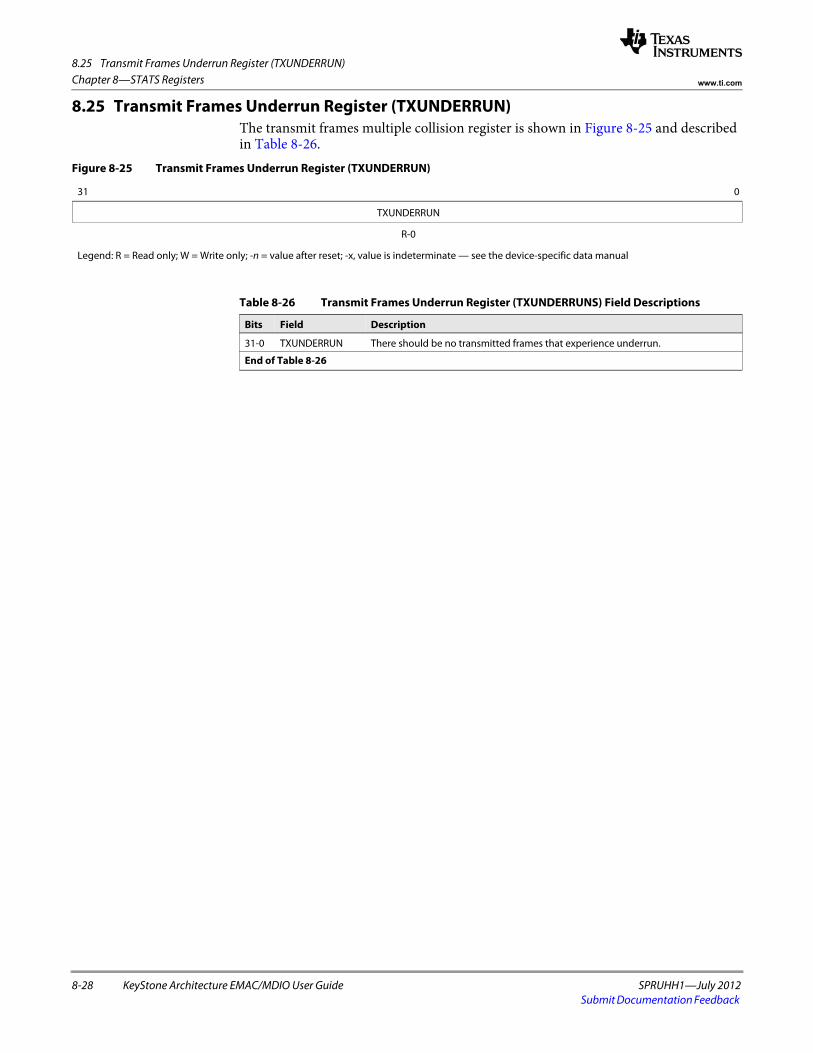
8.25 Transmit Frames Underrun Register (TXUNDERRUN)
8-28 KeyStone Architecture EMAC/MDIO User Guide SPRUHH1—July 2012Submit Documentation Feedback
Chapter 8—STATS Registers www.ti.com
8.25 Transmit Frames Underrun Register (TXUNDERRUN)The transmit frames multiple collision register is shown in Figure 8-25 and described in Table 8-26.
Figure 8-25 Transmit Frames Underrun Register (TXUNDERRUN)
31 0
TXUNDERRUN
R-0
Legend: R = Read only; W = Write only; -n = value after reset; -x, value is indeterminate — see the device-specific data manual
Table 8-26 Transmit Frames Underrun Register (TXUNDERRUNS) Field Descriptions
Bits Field Description
31-0 TXUNDERRUN There should be no transmitted frames that experience underrun.
End of Table 8-26
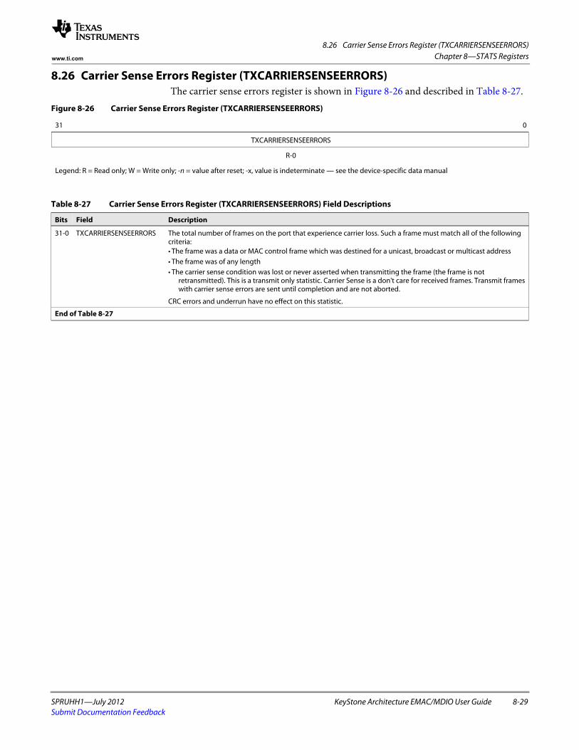
8.26 Carrier Sense Errors Register (TXCARRIERSENSEERRORS)
SPRUHH1—July 2012 KeyStone Architecture EMAC/MDIO User Guide 8-29Submit Documentation Feedback
Chapter 8—STATS Registerswww.ti.com
8.26 Carrier Sense Errors Register (TXCARRIERSENSEERRORS)The carrier sense errors register is shown in Figure 8-26 and described in Table 8-27.
Figure 8-26 Carrier Sense Errors Register (TXCARRIERSENSEERRORS)
31 0
TXCARRIERSENSEERRORS
R-0
Legend: R = Read only; W = Write only; -n = value after reset; -x, value is indeterminate — see the device-specific data manual
Table 8-27 Carrier Sense Errors Register (TXCARRIERSENSEERRORS) Field Descriptions
Bits Field Description
31-0 TXCARRIERSENSEERRORS The total number of frames on the port that experience carrier loss. Such a frame must match all of the following criteria:• The frame was a data or MAC control frame which was destined for a unicast, broadcast or multicast address• The frame was of any length• The carrier sense condition was lost or never asserted when transmitting the frame (the frame is not
retransmitted). This is a transmit only statistic. Carrier Sense is a don't care for received frames. Transmit frames with carrier sense errors are sent until completion and are not aborted.
CRC errors and underrun have no effect on this statistic.
End of Table 8-27
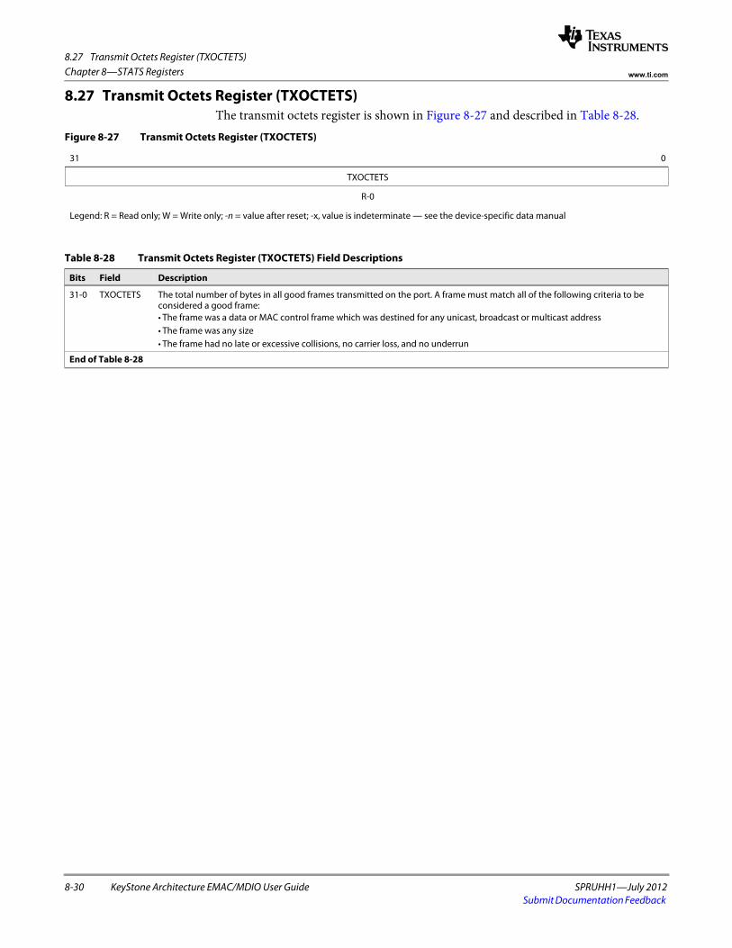
8.27 Transmit Octets Register (TXOCTETS)
8-30 KeyStone Architecture EMAC/MDIO User Guide SPRUHH1—July 2012Submit Documentation Feedback
Chapter 8—STATS Registers www.ti.com
8.27 Transmit Octets Register (TXOCTETS)The transmit octets register is shown in Figure 8-27 and described in Table 8-28.
Figure 8-27 Transmit Octets Register (TXOCTETS)
31 0
TXOCTETS
R-0
Legend: R = Read only; W = Write only; -n = value after reset; -x, value is indeterminate — see the device-specific data manual
Table 8-28 Transmit Octets Register (TXOCTETS) Field Descriptions
Bits Field Description
31-0 TXOCTETS The total number of bytes in all good frames transmitted on the port. A frame must match all of the following criteria to be considered a good frame:• The frame was a data or MAC control frame which was destined for any unicast, broadcast or multicast address• The frame was any size• The frame had no late or excessive collisions, no carrier loss, and no underrun
End of Table 8-28
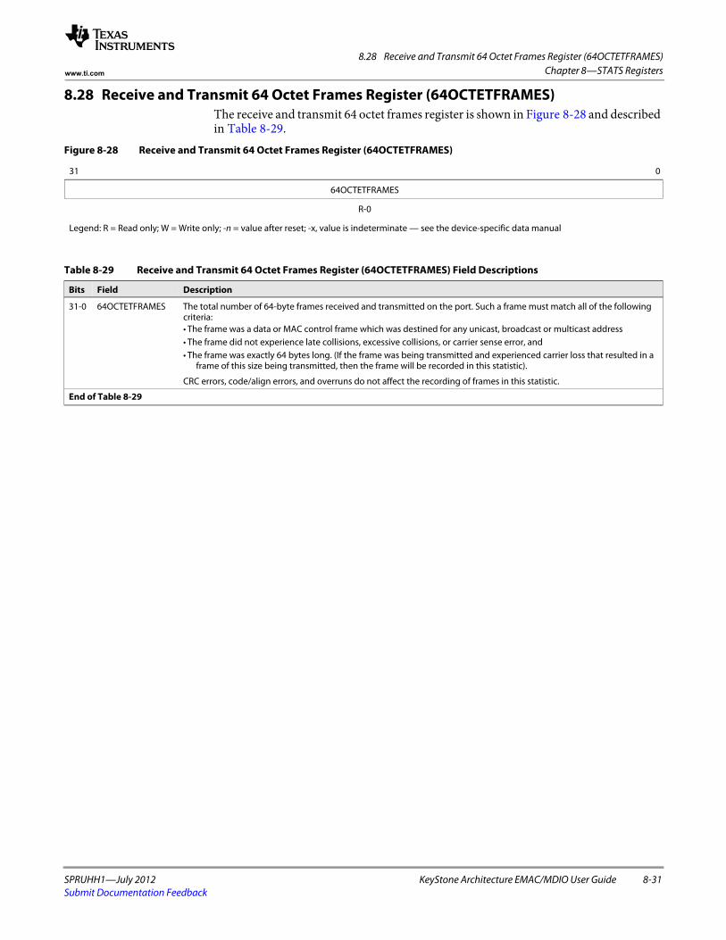
8.28 Receive and Transmit 64 Octet Frames Register (64OCTETFRAMES)
SPRUHH1—July 2012 KeyStone Architecture EMAC/MDIO User Guide 8-31Submit Documentation Feedback
Chapter 8—STATS Registerswww.ti.com
8.28 Receive and Transmit 64 Octet Frames Register (64OCTETFRAMES)The receive and transmit 64 octet frames register is shown in Figure 8-28 and described in Table 8-29.
Figure 8-28 Receive and Transmit 64 Octet Frames Register (64OCTETFRAMES)
31 0
64OCTETFRAMES
R-0
Legend: R = Read only; W = Write only; -n = value after reset; -x, value is indeterminate — see the device-specific data manual
Table 8-29 Receive and Transmit 64 Octet Frames Register (64OCTETFRAMES) Field Descriptions
Bits Field Description
31-0 64OCTETFRAMES The total number of 64-byte frames received and transmitted on the port. Such a frame must match all of the following criteria:• The frame was a data or MAC control frame which was destined for any unicast, broadcast or multicast address• The frame did not experience late collisions, excessive collisions, or carrier sense error, and• The frame was exactly 64 bytes long. (If the frame was being transmitted and experienced carrier loss that resulted in a
frame of this size being transmitted, then the frame will be recorded in this statistic).
CRC errors, code/align errors, and overruns do not affect the recording of frames in this statistic.
End of Table 8-29
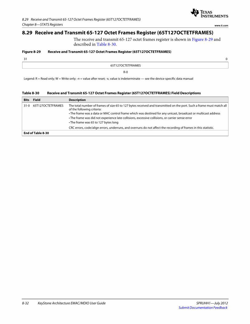
8.29 Receive and Transmit 65-127 Octet Frames Register (65T127OCTETFRAMES)
8-32 KeyStone Architecture EMAC/MDIO User Guide SPRUHH1—July 2012Submit Documentation Feedback
Chapter 8—STATS Registers www.ti.com
8.29 Receive and Transmit 65-127 Octet Frames Register (65T127OCTETFRAMES)The receive and transmit 65-127 octet frames register is shown in Figure 8-29 and described in Table 8-30.
Figure 8-29 Receive and Transmit 65-127 Octet Frames Register (65T127OCTETFRAMES)
31 0
65T127OCTETFRAMES
R-0
Legend: R = Read only; W = Write only; -n = value after reset; -x, value is indeterminate — see the device-specific data manual
Table 8-30 Receive and Transmit 65-127 Octet Frames Register (65T127OCTETFRAMES) Field Descriptions
Bits Field Description
31-0 65T127OCTETFRAMES The total number of frames of size 65 to 127 bytes received and transmitted on the port. Such a frame must match all of the following criteria:• The frame was a data or MAC control frame which was destined for any unicast, broadcast or multicast address• The frame was did not experience late collisions, excessive collisions, or carrier sense error• The frame was 65 to 127 bytes long
CRC errors, code/align errors, underruns, and overruns do not affect the recording of frames in this statistic.
End of Table 8-30
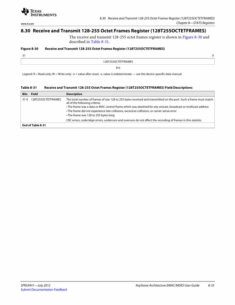
8.30 Receive and Transmit 128-255 Octet Frames Register (128T255OCTETFRAMES)
SPRUHH1—July 2012 KeyStone Architecture EMAC/MDIO User Guide 8-33Submit Documentation Feedback
Chapter 8—STATS Registerswww.ti.com
8.30 Receive and Transmit 128-255 Octet Frames Register (128T255OCTETFRAMES)The receive and transmit 128-255 octet frames register is shown in Figure 8-30 and described in Table 8-31.
Figure 8-30 Receive and Transmit 128-255 Octet Frames Register (128T255OCTETFRAMES)
31 0
128T255OCTETFRAMES
R-0
Legend: R = Read only; W = Write only; -n = value after reset; -x, value is indeterminate — see the device-specific data manual
Table 8-31 Receive and Transmit 128-255 Octet Frames Register (128T255OCTETFRAMES) Field Descriptions
Bits Field Description
31-0 128T255OCTETFRAMES The total number of frames of size 128 to 255 bytes received and transmitted on the port. Such a frame must match all of the following criteria:• The frame was a data or MAC control frame which was destined for any unicast, broadcast or multicast address• The frame did not experience late collisions, excessive collisions, or carrier sense error• The frame was 128 to 255 bytes long
CRC errors, code/align errors, underruns and overruns do not affect the recording of frames in this statistic.
End of Table 8-31

8.31 Receive and Transmit 256-511 Octet Frames Register (256T511OCTETFRAMES)
8-34 KeyStone Architecture EMAC/MDIO User Guide SPRUHH1—July 2012Submit Documentation Feedback
Chapter 8—STATS Registers www.ti.com
8.31 Receive and Transmit 256-511 Octet Frames Register (256T511OCTETFRAMES)The receive and transmit 256-511 octet frames register is shown in Figure 8-31 and described in Table 8-32.
Figure 8-31 Receive and Transmit 256-511 Octet Frames Register (256T511OCTETFRAMES)
31 0
256T511OCTETFRAMES
R-0
Legend: R = Read only; W = Write only; -n = value after reset; -x, value is indeterminate — see the device-specific data manual
Table 8-32 Receive and Transmit 256-511 Octet Frames Register (256T511OCTETFRAMES) Field Descriptions
Bits Field Description
31-0 256T511OCTETFRAMES The total number of frames of size 256 to 511 bytes received and transmitted on the port. Such a frame must match all of the following criteria:• The frame was a data or MAC control frame which was destined for any unicast, broadcast or multicast address• The frame did not experience late collisions, excessive collisions, or carrier sense error• The frame was 256 to 511 bytes long
CRC errors, code/align errors, underruns and overruns do not affect the recording of frames in this statistic.
End of Table 8-32
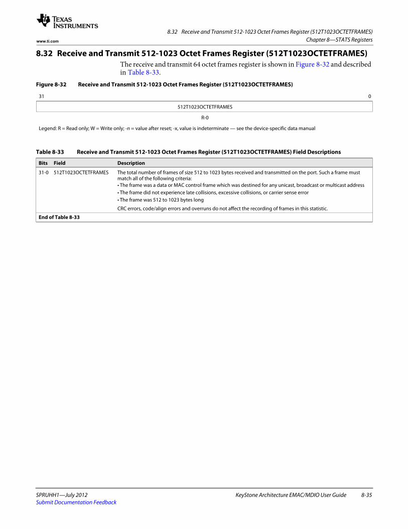
8.32 Receive and Transmit 512-1023 Octet Frames Register (512T1023OCTETFRAMES)
SPRUHH1—July 2012 KeyStone Architecture EMAC/MDIO User Guide 8-35Submit Documentation Feedback
Chapter 8—STATS Registerswww.ti.com
8.32 Receive and Transmit 512-1023 Octet Frames Register (512T1023OCTETFRAMES)The receive and transmit 64 octet frames register is shown in Figure 8-32 and described in Table 8-33.
Figure 8-32 Receive and Transmit 512-1023 Octet Frames Register (512T1023OCTETFRAMES)
31 0
512T1023OCTETFRAMES
R-0
Legend: R = Read only; W = Write only; -n = value after reset; -x, value is indeterminate — see the device-specific data manual
Table 8-33 Receive and Transmit 512-1023 Octet Frames Register (512T1023OCTETFRAMES) Field Descriptions
Bits Field Description
31-0 512T1023OCTETFRAMES The total number of frames of size 512 to 1023 bytes received and transmitted on the port. Such a frame must match all of the following criteria:• The frame was a data or MAC control frame which was destined for any unicast, broadcast or multicast address• The frame did not experience late collisions, excessive collisions, or carrier sense error• The frame was 512 to 1023 bytes long
CRC errors, code/align errors and overruns do not affect the recording of frames in this statistic.
End of Table 8-33
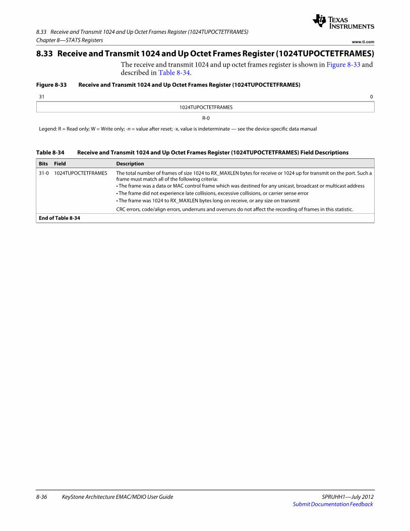
8.33 Receive and Transmit 1024 and Up Octet Frames Register (1024TUPOCTETFRAMES)
8-36 KeyStone Architecture EMAC/MDIO User Guide SPRUHH1—July 2012Submit Documentation Feedback
Chapter 8—STATS Registers www.ti.com
8.33 Receive and Transmit 1024 and Up Octet Frames Register (1024TUPOCTETFRAMES)The receive and transmit 1024 and up octet frames register is shown in Figure 8-33 and described in Table 8-34.
Figure 8-33 Receive and Transmit 1024 and Up Octet Frames Register (1024TUPOCTETFRAMES)
31 0
1024TUPOCTETFRAMES
R-0
Legend: R = Read only; W = Write only; -n = value after reset; -x, value is indeterminate — see the device-specific data manual
Table 8-34 Receive and Transmit 1024 and Up Octet Frames Register (1024TUPOCTETFRAMES) Field Descriptions
Bits Field Description
31-0 1024TUPOCTETFRAMES The total number of frames of size 1024 to RX_MAXLEN bytes for receive or 1024 up for transmit on the port. Such a frame must match all of the following criteria:• The frame was a data or MAC control frame which was destined for any unicast, broadcast or multicast address• The frame did not experience late collisions, excessive collisions, or carrier sense error• The frame was 1024 to RX_MAXLEN bytes long on receive, or any size on transmit
CRC errors, code/align errors, underruns and overruns do not affect the recording of frames in this statistic.
End of Table 8-34
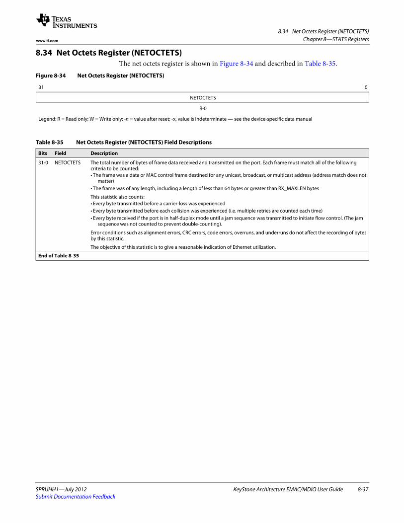
8.34 Net Octets Register (NETOCTETS)
SPRUHH1—July 2012 KeyStone Architecture EMAC/MDIO User Guide 8-37Submit Documentation Feedback
Chapter 8—STATS Registerswww.ti.com
8.34 Net Octets Register (NETOCTETS)The net octets register is shown in Figure 8-34 and described in Table 8-35.
Figure 8-34 Net Octets Register (NETOCTETS)
31 0
NETOCTETS
R-0
Legend: R = Read only; W = Write only; -n = value after reset; -x, value is indeterminate — see the device-specific data manual
Table 8-35 Net Octets Register (NETOCTETS) Field Descriptions
Bits Field Description
31-0 NETOCTETS The total number of bytes of frame data received and transmitted on the port. Each frame must match all of the following criteria to be counted:• The frame was a data or MAC control frame destined for any unicast, broadcast, or multicast address (address match does not
matter)• The frame was of any length, including a length of less than 64 bytes or greater than RX_MAXLEN bytes
This statistic also counts:• Every byte transmitted before a carrier-loss was experienced• Every byte transmitted before each collision was experienced (i.e. multiple retries are counted each time)• Every byte received if the port is in half-duplex mode until a jam sequence was transmitted to initiate flow control. (The jam
sequence was not counted to prevent double-counting).
Error conditions such as alignment errors, CRC errors, code errors, overruns, and underruns do not affect the recording of bytes by this statistic.
The objective of this statistic is to give a reasonable indication of Ethernet utilization.
End of Table 8-35
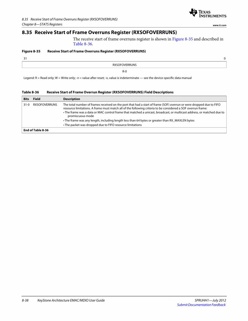
8.35 Receive Start of Frame Overruns Register (RXSOFOVERRUNS)
8-38 KeyStone Architecture EMAC/MDIO User Guide SPRUHH1—July 2012Submit Documentation Feedback
Chapter 8—STATS Registers www.ti.com
8.35 Receive Start of Frame Overruns Register (RXSOFOVERRUNS)The receive start of frame overruns register is shown in Figure 8-35 and described in Table 8-36.
Figure 8-35 Receive Start of Frame Overruns Register (RXSOFOVERRUNS)
31 0
RXSOFOVERRUNS
R-0
Legend: R = Read only; W = Write only; -n = value after reset; -x, value is indeterminate — see the device-specific data manual
Table 8-36 Receive Start of Frame Overrun Register (RXSOFOVERRUNS) Field Descriptions
Bits Field Description
31-0 RXSOFOVERRUNS The total number of frames received on the port that had a start of frame (SOF) overrun or were dropped due to FIFO resource limitations. A frame must match all of the following criteria to be considered a SOF overrun frame:• The frame was a data or MAC control frame that matched a unicast, broadcast, or multicast address, or matched due to
promiscuous mode• The frame was any length, including length less than 64 bytes or greater than RX_MAXLEN bytes• The packet was dropped due to FIFO resource limitations
End of Table 8-36
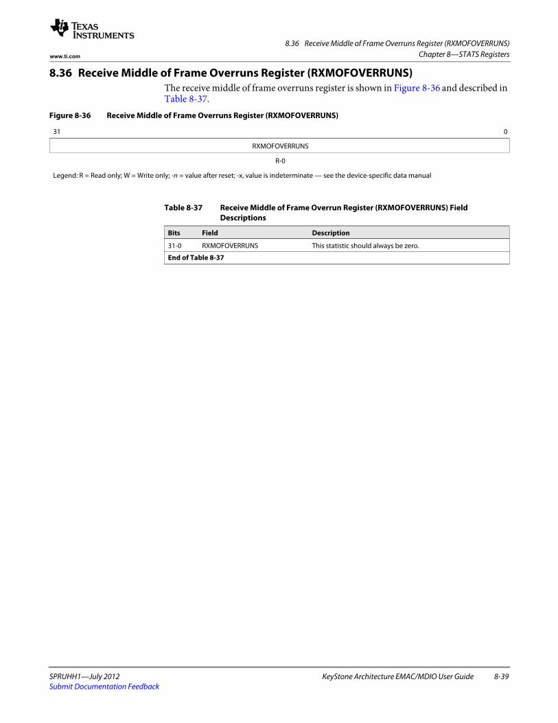
8.36 Receive Middle of Frame Overruns Register (RXMOFOVERRUNS)
SPRUHH1—July 2012 KeyStone Architecture EMAC/MDIO User Guide 8-39Submit Documentation Feedback
Chapter 8—STATS Registerswww.ti.com
8.36 Receive Middle of Frame Overruns Register (RXMOFOVERRUNS)The receive middle of frame overruns register is shown in Figure 8-36 and described in Table 8-37.
Figure 8-36 Receive Middle of Frame Overruns Register (RXMOFOVERRUNS)
31 0
RXMOFOVERRUNS
R-0
Legend: R = Read only; W = Write only; -n = value after reset; -x, value is indeterminate — see the device-specific data manual
Table 8-37 Receive Middle of Frame Overrun Register (RXMOFOVERRUNS) Field Descriptions
Bits Field Description
31-0 RXMOFOVERRUNS This statistic should always be zero.
End of Table 8-37
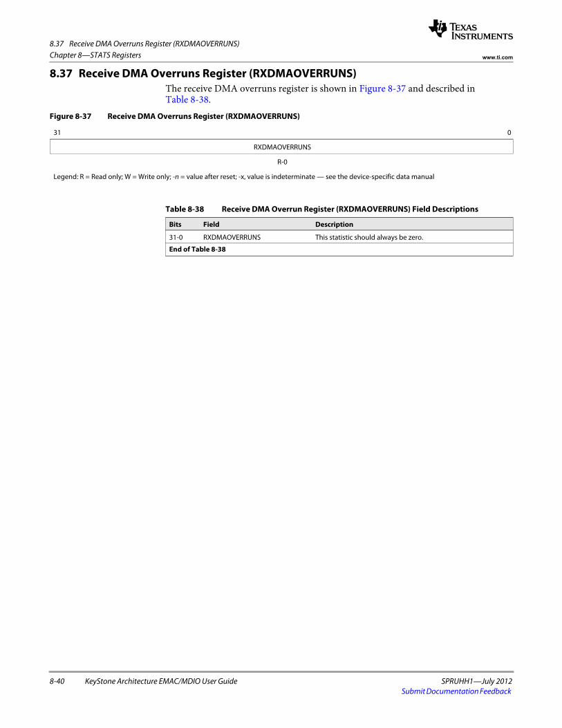
8.37 Receive DMA Overruns Register (RXDMAOVERRUNS)
8-40 KeyStone Architecture EMAC/MDIO User Guide SPRUHH1—July 2012Submit Documentation Feedback
Chapter 8—STATS Registers www.ti.com
8.37 Receive DMA Overruns Register (RXDMAOVERRUNS)The receive DMA overruns register is shown in Figure 8-37 and described in Table 8-38.
Figure 8-37 Receive DMA Overruns Register (RXDMAOVERRUNS)
31 0
RXDMAOVERRUNS
R-0
Legend: R = Read only; W = Write only; -n = value after reset; -x, value is indeterminate — see the device-specific data manual
Table 8-38 Receive DMA Overrun Register (RXDMAOVERRUNS) Field Descriptions
Bits Field Description
31-0 RXDMAOVERRUNS This statistic should always be zero.
End of Table 8-38

SPRUHH1—July 2012 KeyStone Architecture EMAC/MDIO User Guide A-1Submit Documentation Feedback
Appendix A
Glossary
Broadcast MAC Address — A special Ethernet MAC address used to send data to all Ethernet devices on the local network The broadcast address is FFh-FFh-FFh-FFh-FFh-FFh. The LSB of the first byte is odd, qualifying it as a group address; however, its value is reserved for broadcast. It is classified separately by the EMAC.
Descriptor (Packet Buffer Descriptor) —A small memory structure that describes a larger block of memory in terms of size, location, and state. Descriptors are used by the EMAC and application to describe the memory buffers that hold Ethernet data.
Device —In this document, device refers to the TMS320C6657 processor.
Ethernet MAC Address (MAC Address) —A unique 6-byte address that identifies an Ethernet device on the network. In an Ethernet packet, a MAC address is used twice, first to identify the packets destination, and second to identify the packets sender or source. An Ethernet MAC address is normally specified in hexadecimal, using dashes to separate bytes. For example, 08h-00h-28h-32h-1 7h-42h.
The first three bytes normally designate the manufacturer of the device. However, when the first byte of the address is odd (LSB is 1), the address is a group address (broadcast or multicast). The second bit specifies whether the address is globally or locally administrated (not considered in this document).
Ethernet Packet (Packet) —An Ethernet packet is the collection of bytes that represents the data portion of a single Ethernet frame on the wire.
Full Duplex —Full duplex operation allows simultaneous communication between a pair of stations using point-to-point media (dedicated channel). Full duplex operation does not require that transmitters defer, nor do they monitor or react to receive activity, as there is no contention for a shared medium in this mode. Full duplex mode can only be used when all of the following are true:
• The physical medium is capable of supporting simultaneous transmission and reception without interference.
• There are exactly two stations connected with a full duplex point-to-point link. As there is no contention for use of a shared medium, the multiple access (i.e., CSMA/CD) algorithms are unnecessary.
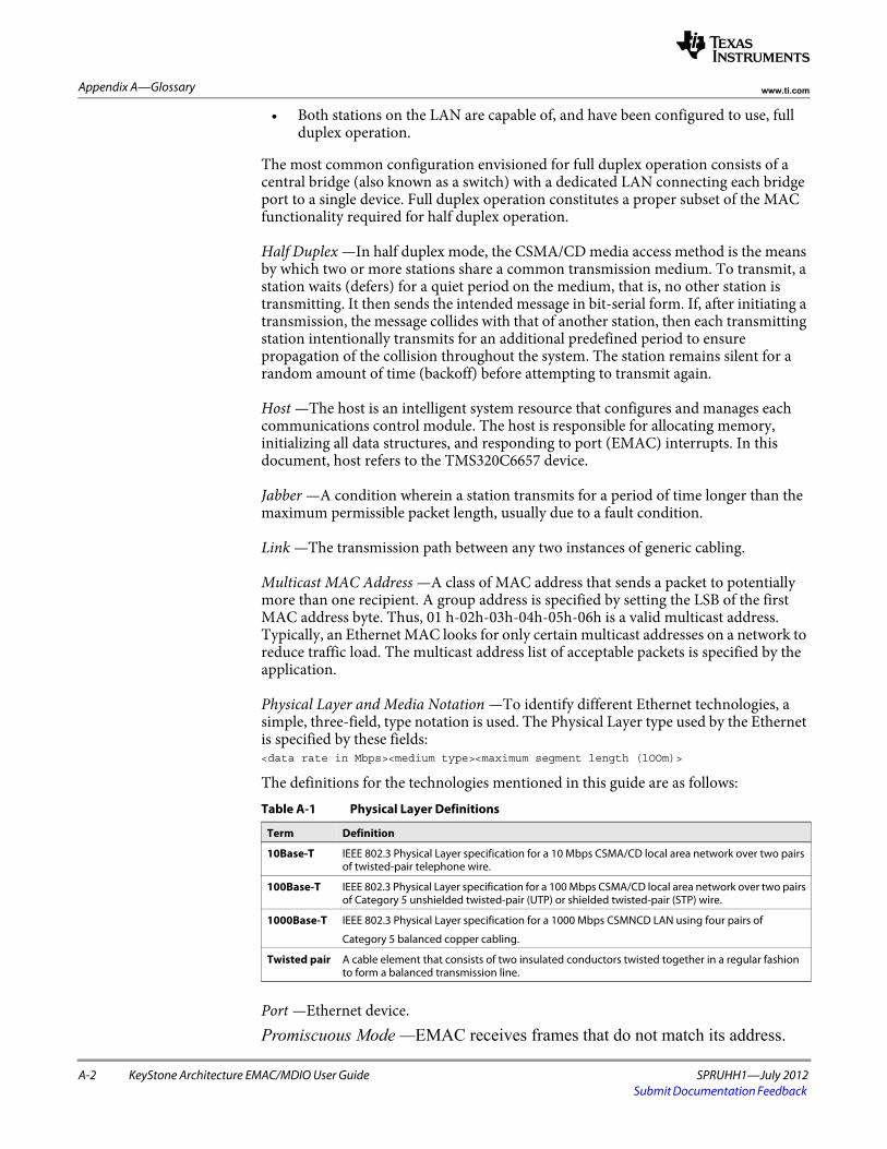
A-2 KeyStone Architecture EMAC/MDIO User Guide SPRUHH1—July 2012Submit Documentation Feedback
Appendix A—Glossary www.ti.com
• Both stations on the LAN are capable of, and have been configured to use, full duplex operation.
The most common configuration envisioned for full duplex operation consists of a central bridge (also known as a switch) with a dedicated LAN connecting each bridge port to a single device. Full duplex operation constitutes a proper subset of the MAC functionality required for half duplex operation.
Half Duplex —In half duplex mode, the CSMA/CD media access method is the means by which two or more stations share a common transmission medium. To transmit, a station waits (defers) for a quiet period on the medium, that is, no other station is transmitting. It then sends the intended message in bit-serial form. If, after initiating a transmission, the message collides with that of another station, then each transmitting station intentionally transmits for an additional predefined period to ensure propagation of the collision throughout the system. The station remains silent for a random amount of time (backoff) before attempting to transmit again.
Host —The host is an intelligent system resource that configures and manages each communications control module. The host is responsible for allocating memory, initializing all data structures, and responding to port (EMAC) interrupts. In this document, host refers to the TMS320C6657 device.
Jabber —A condition wherein a station transmits for a period of time longer than the maximum permissible packet length, usually due to a fault condition.
Link —The transmission path between any two instances of generic cabling.
Multicast MAC Address —A class of MAC address that sends a packet to potentially more than one recipient. A group address is specified by setting the LSB of the first MAC address byte. Thus, 01 h-02h-03h-04h-05h-06h is a valid multicast address. Typically, an Ethernet MAC looks for only certain multicast addresses on a network to reduce traffic load. The multicast address list of acceptable packets is specified by the application.
Physical Layer and Media Notation —To identify different Ethernet technologies, a simple, three-field, type notation is used. The Physical Layer type used by the Ethernet is specified by these fields: <data rate in Mbps><medium type><maximum segment length (lOOm)>
The definitions for the technologies mentioned in this guide are as follows:
Port —Ethernet device. Promiscuous Mode —EMAC receives frames that do not match its address.
Table A-1 Physical Layer Definitions
Term Definition
10Base-T IEEE 802.3 Physical Layer specification for a 10 Mbps CSMA/CD local area network over two pairs of twisted-pair telephone wire.
100Base-T IEEE 802.3 Physical Layer specification for a 100 Mbps CSMA/CD local area network over two pairs of Category 5 unshielded twisted-pair (UTP) or shielded twisted-pair (STP) wire.
1000Base-T IEEE 802.3 Physical Layer specification for a 1000 Mbps CSMNCD LAN using four pairs of
Category 5 balanced copper cabling.
Twisted pair A cable element that consists of two insulated conductors twisted together in a regular fashion to form a balanced transmission line.

IMPORTANT NOTICE
Texas Instruments Incorporated and its subsidiaries (TI) reserve the right to make corrections, modifications, enhancements, improvements,and other changes to its products and services at any time and to discontinue any product or service without notice. Customers shouldobtain the latest relevant information before placing orders and should verify that such information is current and complete. All products aresold subject to TI’s terms and conditions of sale supplied at the time of order acknowledgment.
TI warrants performance of its hardware products to the specifications applicable at the time of sale in accordance with TI’s standardwarranty. Testing and other quality control techniques are used to the extent TI deems necessary to support this warranty. Except wheremandated by government requirements, testing of all parameters of each product is not necessarily performed.
TI assumes no liability for applications assistance or customer product design. Customers are responsible for their products andapplications using TI components. To minimize the risks associated with customer products and applications, customers should provideadequate design and operating safeguards.
TI does not warrant or represent that any license, either express or implied, is granted under any TI patent right, copyright, mask work right,or other TI intellectual property right relating to any combination, machine, or process in which TI products or services are used. Informationpublished by TI regarding third-party products or services does not constitute a license from TI to use such products or services or awarranty or endorsement thereof. Use of such information may require a license from a third party under the patents or other intellectualproperty of the third party, or a license from TI under the patents or other intellectual property of TI.
Reproduction of TI information in TI data books or data sheets is permissible only if reproduction is without alteration and is accompaniedby all associated warranties, conditions, limitations, and notices. Reproduction of this information with alteration is an unfair and deceptivebusiness practice. TI is not responsible or liable for such altered documentation. Information of third parties may be subject to additionalrestrictions.
Resale of TI products or services with statements different from or beyond the parameters stated by TI for that product or service voids allexpress and any implied warranties for the associated TI product or service and is an unfair and deceptive business practice. TI is notresponsible or liable for any such statements.
TI products are not authorized for use in safety-critical applications (such as life support) where a failure of the TI product would reasonablybe expected to cause severe personal injury or death, unless officers of the parties have executed an agreement specifically governingsuch use. Buyers represent that they have all necessary expertise in the safety and regulatory ramifications of their applications, andacknowledge and agree that they are solely responsible for all legal, regulatory and safety-related requirements concerning their productsand any use of TI products in such safety-critical applications, notwithstanding any applications-related information or support that may beprovided by TI. Further, Buyers must fully indemnify TI and its representatives against any damages arising out of the use of TI products insuch safety-critical applications.
TI products are neither designed nor intended for use in military/aerospace applications or environments unless the TI products arespecifically designated by TI as military-grade or "enhanced plastic." Only products designated by TI as military-grade meet militaryspecifications. Buyers acknowledge and agree that any such use of TI products which TI has not designated as military-grade is solely atthe Buyer's risk, and that they are solely responsible for compliance with all legal and regulatory requirements in connection with such use.
TI products are neither designed nor intended for use in automotive applications or environments unless the specific TI products aredesignated by TI as compliant with ISO/TS 16949 requirements. Buyers acknowledge and agree that, if they use any non-designatedproducts in automotive applications, TI will not be responsible for any failure to meet such requirements.
Following are URLs where you can obtain information on other Texas Instruments products and application solutions:
Products Applications
Audio www.ti.com/audio Automotive and Transportation www.ti.com/automotive
Amplifiers amplifier.ti.com Communications and Telecom www.ti.com/communications
Data Converters dataconverter.ti.com Computers and Peripherals www.ti.com/computers
DLP® Products www.dlp.com Consumer Electronics www.ti.com/consumer-apps
DSP dsp.ti.com Energy and Lighting www.ti.com/energy
Clocks and Timers www.ti.com/clocks Industrial www.ti.com/industrial
Interface interface.ti.com Medical www.ti.com/medical
Logic logic.ti.com Security www.ti.com/security
Power Mgmt power.ti.com Space, Avionics and Defense www.ti.com/space-avionics-defense
Microcontrollers microcontroller.ti.com Video and Imaging www.ti.com/video
RFID www.ti-rfid.com
OMAP Mobile Processors www.ti.com/omap
Wireless Connectivity www.ti.com/wirelessconnectivity
TI E2E Community Home Page e2e.ti.com
Mailing Address: Texas Instruments, Post Office Box 655303, Dallas, Texas 75265Copyright © 2012, Texas Instruments Incorporated