etd 16/ t 1 6 - bisbis.org.in/sf/etd/etd16(6824)_13012016.pdf · etd 16/ t - 3- 1 - 6 å! Ð ! e +...
TRANSCRIPT

DRAFTS IN WIDE
CIRCULATION
Document Despatch Advice
TECHNICAL COMMITTEE ETD 16
-------------------------------------------------------------------------------------------------------------------
ADDRESSED TO:
1. All Members of Transformers Sectional Committee, ETD 16;
2. All Members of Electrotechnical Division Council; and
3. All other Interested.
Dear Sir(s),
Please find enclosed a copy each of the following draft Indian Standards:
DOC NO. TITLE
ETD 16(6824) Outdoor type, insula ted l iquid immersed distr ibut ion
transformers Upto and includ ing 2500 kva, 33 kv –
spec i fica t ion
(par t 2 : Ester fluid immersed )
Kindly examine the draft standards and forward your views stating any difficulties which you are likely to
experience in your business or profession, if these are finally adopted as Indian Standards.
Comments, if any, may please be made in the format given overleaf and mailed to the undersigned.
Last date for comments: 12-03-2016.
In case no comments are received or comments received are of editorial nature, you will kindly permit us to
presume your approval for the above document as finalized. However, in case of comments of technical in
nature are received then it may be finalized either in consultation with the Chairman, Sectional Committee or
referred to the Sectional Committee for further necessary action, if so desired by the Chairman, Sectional
Committee.
It may kindly be noted that the technical contents of the documents has not been enclosed as these are
identical with the corresponding IEC standards. For details, please refer to the corres ponding IEC
publication as mentioned in the respective National Forewords or kindly contact the undersigned.
Thanking you,
Yours faithfully
(D. Goswami)
Sc ‘F’ & Head (Electrotechnical)
Email: [email protected]
Encl: As above
REFERENCE Date
ETD 16/ T- 2 13-01-2016

या प चाला म म द
र खर षणदञा म
तपमीपीदम तत:ईटी 16
---------------------------------------------------------------------------
------------------------------------------------------------------
रषती :
1. ईटी 16 क सभी सद य
2. वियत तकनीकी विभाग परिषद क सभी सद य ताा
3. चि िखन िाल अ य सभी िनकाय
मह दय,
क या िन नलल खखत मस द की एक रित सल न ह :
रलख शीषषक
रलख शीषषक
ईटीडी16(6824) २५०० प वी ए, ३३ प वी तप प आउटडोा टाइ ,ववधयताोधी रवतम जित ववताण ादफा मा― ववमिटटभाग२:ईटाऑय मतम जित
क या न मस द का अिल कन कि औि अपनी स मितय यह ततात हए भ िक अतत: यिद यह मानक क प म रकालशत ह ाए त स पि अमल किन म आपक यिसाय अािा काि ताि म या किाना य आ सकती ह।
स मितय भ न की अितम तािीख 12-03-2016
स मितय यिद क ई ह त क या अगल प ा पि िदए प म अो ह ताीिी क रपरिललखखत पत पि भ द
यिद क ई स मित रा त नही ह ती अािा स मित म किल भाषा सतोी िट हई त रपि त रलख क यााित अितम प िदया ाएगा यिद क ई स मित तकनीकी रकित की हई त विषय सलमित क अ यी क पिामशष स अािा रनकी छा पि आग की कायषिाही क ललए विषय सलमित क भ ान क ताद रलख क अितम प द िदया ाएगा
कपया न ट कि िक मस द का तकनीकी विषय ि त सल नत नही िकया गया ह यिक य मस द आई. ई. सी. मानक क समप ह। वि तत य ि क ललए कपया सतचोत िा रीय रा कान म रिलखखत आई. ई. सी. रकाशन पढ अािा अो ह ताीरित क सपकष कि
ो यिाद,
भिदीय,
।डीगोवा ी।
वञातमपएफएवर ख (ववयततपमीपी)
सल न : रपरिललखखत
द भम ईटीडी द माप
ईटीडी16/ टी-2 13-01-2016

Date Document No. 13-01-2016 Doc: ET 16(6824)
Sl. No.
Name of the Organization
Clause/
Sub-clause
Paragraph/ Figure/Tabl
e
Type of Comment (General/
Technical/ Editorial
Comments Proposed
Change

0
Doc: ETD 16 (6824 )
Draft IS 1180 (Part 2) : 2016
Transformers Sectional Committee, ETD 16
FOREWORD
This Indian Standard, IS 1180 (Part 2): 2016 was adopted by the Bureau of Indian Standards, after
the draft finalised by the Transformers Sectional Committee, had been approved by the
Electrotechnical Division Council.
IS 1180 (Part 1): 2014 addresses specification of Mineral Oil immersed, Outdoor type distribution
Transformers up to 2500 kVA 33 kV.
A note under cl. 9.1 of the said standard allowed use of other insulating liquids namely natural
ester, synthetic organic ester subject to agreement between the user and the supplier.
As mineral oil is semi biodegradable, toxic in nature and is more prone to fire hazards having a
low fire point of the order of 150 °C, use of ester fluids, natural vegetable based esters as well as
synthetic organic esters with fire point above 300 °C in lieu of mineral fluid in several countries
has increased due to fire safety and environmental considerations.
A need was felt to have a separate standard on Distribution transformers filled with Ester fluids
and as decided in 15th
Sectional Committee meeting of ET 16 on 19th
Aug’14, this standard IS
1180 (Part 2) has been formulated.
All other specifications and parameters of these Distribution transformers filled with ester fluids
are same as mineral fluid filled transformers as per IS 1180 (Part 1): 2014 except type of cooling
and temperature rises.
Total losses according to three energy efficiency levels; level 1; level 2 and level 3 as applicable
for mineral oil immersed Distribution transformers as per IS 1180 (Part 1):2014 are also
maintained for ester filled Distribution transformers.
Being ‘K’ class fluid having fire point above 300 °C, the best advantage of the liquid is to work
on higher temperature rises with compatible high temperature material.
This standard explores such possibility based on IEC 60076-14 ‘Liquid-immersed power
transformers using high insulation materials’.
Of the several possibilities of using high temperature insulation system, the standard
recommends, to start with, a semi hybrid insulation system where thermally upgraded paper
(TUP) is used only for the conductor insulation to allow higher than conventional average
winding rises. Based on the availability 130 /140 temperature class of material can also be used.
In due course of time when sufficient experience builds using ester fluids, higher temperature
rises may be recommended using high temperature insulation systems.
Temperature rises as recommended for conventional insulation and mineral oil have also been
kept as an alternative and may be used for retro filling option.
Pad mounted distribution transformers are popular abroad. They are self-protected and obviate the
need of ring main unit as used in prefabricated compact substations up to 33 kV.

1
Such Pad mounted Distribution transformers are also suggested for use in the country up to 33 kV
filled with ester fluids. When sufficient experience builds, a separate standard in IS 1180 series
can be developed to address Pad mounted transformers.
There is no IEC standard on the subject of ester filled Distribution transformers. However,
considerable assistance has been taken while preparing this standard; from IEC 62770 “Unused natural esters for transformers and similar electrical equipment, IEC 61099 “Specification for unused synthetic organic esters for electrical purposes and IEC 60076-14 “Liquid immersed Power transformer using high-temperature insulation materials”.
IS 1180 (Part 1): 2014 is a necessary adjunct to this standard.
For the purpose of deciding whether a particular requirement of this standard is complied with,
the final value, observed or calculated, expressing the result of a test, shall be rounded off in
accordance with IS 2 : 1960 ‘Rules for rounding off numerical values (revised)’. The number of significant places retained in the rounded off value should be the same as that of the specified
value in this standard.
The Distribution Transformers covered by this standard may be marked with the “Standard
Mark”.
The use of the standard mark is governed by the provision of Bureau of Indian Standards Act
1986 and the rules and regulations made thereunder. The details of conditions under which the
license for the use of the standard mark may be granted to manufacturers or producers may be
obtained from the Bureau of Indian Standards.

2
BUREAU OF INDIAN STANDARD
DRAFT FOR COMMENTS ONLY
Doc: ET 16(6824)
Draft IS 1180 (Part 2): 2016
Draft Indian Standard
OUTDOOR TYPE, INSULATED LIQUID IMMERSED DISTRIBUTION
TRANSFORMERS
UPTO AND INCLUDING 2500 kVA, 33 kV – SPECIFICATION
(Part 2: ESTER FLUID IMMERSED)
Last date for comments: 12-03-2016
1. SCOPE
This standard specifies the requirements and tests including standard loss levels of ester oil-
immersed, natural air-cooled, outdoor type, double-wound distribution transformers for use
in Power distribution systems with nominal system voltages up to and including 33 kV and
of following types and ratings:
(a) Three phase ratings up to and including 200 kVA, non-sealed and sealed type.
(b) Three phase ratings higher than 200 kVA up to and including 2500 kVA both non-sealed
type and sealed type.
(c) Single phase ratings up to and including 25 kVA sealed type.
2 REFERENCES
The standards listed in Annex A contain provisions which, through reference in this text,
constitute provisions of this standard. All standards are subject to revision, and parties to
agreements based on this standard are encouraged to investigate the possibility of applying the
most recent editions of the standards listed in Annex A.
Bibliography at Annex E gives list of IEC, IEEE Standards, Cigre brochures etc. on Ester fluids.
3 TERMINOLOGY
For the purpose of this standard, the following terms and definitions shall apply in addition to
those given in IS 1885 (Part 38).
3.1Distribution Transformer
A Distribution Transformer is a transformer that provides the final voltage transformation in the
electric power distribution system, stepping down the voltage used in the distribution lines to the
level used by the customers.
NOTE
The distribution line voltages are 3.3 kV, 6.6 kV, 11 kV, 22 kV and 33 kV in the country. The domestic supply for the consumers is 415 volt, 3
Phase (240 volt, 1 phase), 50 Hz. Transformers with primary voltages of 3.3, 6.6, 11, 22 or 33 kV and secondary voltage of 433 volt, 3 Phase (and
250 volt single phase) are called Distribution Transformers. The maximum rating of these transformers for the purpose of this standard is
considered up to 2500 kVA, 3 Phase.
3.2 Non Sealed type Transformer

3
A transformer which has a conservator and a breather for breathing out and breathing in with
expansion and contraction of fluid with temperature. The transformer tank body and cover are
bolted / clamped / welded type. The tank can also be of corrugated construction.
3.3 Sealed type Transformer
A transformer which is non-breathing that is so sealed that normally there is no significant
interchange between its contents and the external atmosphere. No conservator is provided. Such a
transformer may or may not have a cushion of inert gas (for example; Nitrogen, IS 1747).
Sealed transformers fall in to two categories:
a) Transformers in which the total volume of oil together with inert gas / N2 or any
combination thereof, remains constant over the temperature range.
b) Transformers in which the total volume of fluid, inert gas / N2 or any combination thereof, varies over the temperature range and this variation is accommodated by a
sealed flexible container (corrugated tank) or a flexible membrane.
Sealed type transformers usually have a bolted / clamped / welded cover construction.
3.4 “K” class Insulating Liquids
According to IS 13503 “Classification of Insulating Liquids”, Fluids with fire point above 300 °C
are classified as K class liquids. Synthetic Ester, Natural Ester and Silicon liquids come under this
category. Percentage of biodegradability of silicone liquid is low (around 5 %). For the purpose of
this standard, only Synthetic esters and Natural Esters which are 80 to 100% biodegradable are
considered. Although “fluid” is more appropriate word we have used in the text more popular, “Ester oil” to represent such insulating fluids.
3.5.a. Natural Esters
Vegetable oils obtained from seed (such as soya, rapeseed, and sunflower) and fluids from other
suitable biological materials and comprised of triglycerides are called Natural esters. Suitable
chemical substances called “additives” are deliberately added to natural ester insulating fluids in order to improve certain characteristics, e.g. pour point, viscosity, foaming and oxidation stability.
Natural esters are suitable for sealed transformer and transformers equipped with airbags or
suitable fluid preservation system which prevents direct contact of oxygen with the fluid in the
conservator. Natural Esters are not recommended for free breathing type since oxygen from air
accelerates oxidation of natural esters and which increases the viscosity of the liquid.
3.5.b. Synthetic Esters
By definition an ester is a reaction product from the combination of an acid and an alcohol.
Synthetic esters are manufactured from carefully selected raw materials to give a product that is
tailored to specific application of transformers blended with additives to improve certain
characteristics, e.g. pour point, viscosity, foaming excellent oxidation stability making it suitable
for the breathing system where the fluid has free access to oxygen from air. Synthetic Esters are
suitable for non-sealed and sealed transformers without any preservation system.
3.6 Pad Mounted Transformer

4
An outdoor transformer utilized as part of underground distribution system with enclosed
compartment (s) for high voltage and low voltage cables entering from below and mounted on a
foundation pad.
The pad mounted transformer generally covers two bushing and terminal arrangements for radial
feed systems. It consists of a tank with high voltage and low voltage cable terminating
compartments separated by a barrier of metal or other rigid material. These compartments are
located side by side on one side of the transformer tank. The transformer shall be of sealed
construction.
4 SERVICE CONDITIONS
The provisions of IS 2026 (Part 1) shall apply.
5 GENERAL
Technical parameters including standard loss levels of three categories of Distribution
transformers are given in 6, 7&8.
Other requirements as described in 9 to 22 are applicable for all types and ratings of distribution
transformers.
6 TECHNICAL PARAMETERS OF THREE PHASE DISTRIBUTION
TRANSFORMERS UP TO AND INCLUDING 200 kVA (Non Sealed and Sealed Type)
6.1 Ratings
The standard ratings shall be as per Table 1.
Table 1 Standard ratings
(Clause6.1)
_______________________________________________________________________
Sl No. Nominal System Voltage Standard Ratings (kVA)
(1) (2) (3)
i Up to and including 11 kV *6.3,*10,16, *20,25, *40,63, 100,
160 and 200
ii Above 11 kV up to and including 22 kV 63, 100, 160 and 200
iii Above 22 kV up to and including 33 kV 100, 160 and 200
NOTE -* ratings are non-preferred
6.2 Rated Frequency
The rated frequency shall be 50 Hz.
6.3 Nominal System Voltage
Nominal system voltage shall be chosen from the following:
High Voltage (HV) - 3.3, 6.6, 11, 22 & 33 kV
Low Voltage (LV) - 415V
6.4 Basic Insulation Level (BIL).

5
Rated Basic Insulation Levels shall be as given in Table 2.
TABLE 2 RATED BIL
(Clause6.4)
Sl No. Nominal System Voltage (kV) Rated BIL (kVp)
(1) (2) (3)
i 3.3 40
ii 6.6 60
iii 11 75
iv 22 125
v 33 170
6.5 No-Load Voltage ratios
The no-load voltage ratios shall be as follows:
3 300/433-250, 6 600/433-250, 11 000/433-250, 22 000/433-250 and 33 000/433-250 V
NOTE ― Secondary voltage may be selected as 415-240 V, subject to agreement between User and Supplier
6.6 Winding Connections and Phase Displacement
The primary winding shall be connected in delta and the secondary winding in star [vector
symbol, Dyn 11 (see IS 2026 Part 1)], so as to produce, a positive phase displacement of 30o
from
the primary to the secondary vectors of the same phase. The neutral of the secondary winding
shall be brought out to a separate insulated terminal.
6.7 Tapping Range and Tapping Methods
6.7.1 No taps are normally required to be provided upto 100 kVA rating, unless specifically
specified by the user.
6.7.2 The standard tapping range, when taps are provided above 100 kVA rating shall be as
follows:
Winding tapped HV
Number of tap positions 4
Voltage variation +2 1/2 percent to -5 per cent of HV in steps of 2
1/2 percent
6.7.3 Off circuit Tap-changing arrangement shall be either by means of links or by means of an
externally-operated switch with mechanical locking device and a position indicator. Arrangement
for pad-locking shall be provided.
6.8 Losses and Impedance Values
6.8.1 Losses

6
6.8.1.1 For transformers of HV voltage up to 11 kV, the total losses (no-load + load losses at
750C) at 50 percent of rated load and total losses at 100 percent of rated load shall not exceed the
maximum total loss values given in Table 3:
Table 3 Maximum total losses up to 11kV class Transformers
(Clause6.8.1.1)
NOTE - For non – preferred ratings of Table 1, max losses are subject to agreement between User and Supplier.
6.8.1.2 For transformers having voltage class above 11kV and up to and including 22 kV, the
permissible total loss values shall not exceed by 5 percent of the maximum total loss values
mentioned in table 3.
6.8.1.3 For transformers having voltage class above 22 kV and up to and including 33 kV, the
permissible total loss values shall not exceed by 7 ½ percent of the maximum total loss values
mentioned in table 3.
6.8.2 Impedance
The recommended impedance at 75ºC for different ratings is as per Table 3.
6.9 Permissible Flux Density and over fluxing
6.9.1 The maximum flux density in any part of the core and yoke at rated voltage and frequency
shall be such that the flux density with + 12.5 percent combined voltage and frequency variation
from rated voltage and frequency shall not exceed 1.9 Tesla.
NOTE The design calculations in support of flux density shall be furnished by manufacturer.
6.9.2 No load current up to 200 kVA shall not exceed 3 percent of full load current and will be
measured by energizing the transformer at rated voltage and frequency. Increase of 12.5 percent
of rated voltage shall not increase the no load current by 6 percent maximum of full load current.
S.No Rating
(kVA)
Impedance
(percent)
Max. Total Loss (W)
Energy Efficiency
Level 1
Energy Efficiency
Level 2
Energy Efficiency
Level 3
50 %
Load
100 %
Load
50 %
Load
100 %
Load
50 %
Load
100 %
Load
i 16 4.5 150 480 135 440 120 400
ii 25 4.5 210 695 190 635 175 595
iii 63 4.5 380 1250 340 1140 300 1050
iv 100 4.5 520 1800 475 1650 435 1500
v 160 4.5 770 2200 670 1950 570 1700
vi 200 4.5 890 2700 780 2300 670 2100

7
6.10 Limits of Temperature-Rise
6.10.1 The type of cooling shall be type KNAN as per IS 2026 (Part 2).
6.10.2 The permissible temperature-rise shall not exceed the limits of 40oC (when measured by
resistance method) for transformer winding and 35oC (measured by thermometer) for top fluid
when tested in accordance with IS 2026 (Part 2) when conventional insulation system is used (as
for retro filling).The marginal increase in temperature rises by use of Ester fluids is ignored (since
this is compensated by slow ageing).
6.10.3 The permissible temperature rise will not exceed the limit of 55oC (when measured by
resistance method) for transformer winding and 50oC (measured by thermometer by oil when
tested in accordance with IS 2026 (Part 2) when semi hybrid high temperature insulation in
accordance with IEC 60076-14 (2013).
Note ― Semi hybrid insulation system consists of mainly high temperature solid insulation materials thermally upgraded paper (TUP) used for
windings alone.
During temperature rise test, total losses at 75 oC shall be fed.
7 TECHNICAL PARAMETERS OF THREE PHASE DISTRIBUTION
TRANSFORMERS HIGHER THAN 200 kVA UP TO AND INCLUDING 2500 kVA (NON
SEALED AND SEALED TYPE)
7.1 Ratings
The standard ratings shall be as per Table 4.
Table 4 Standard ratings
(Clause7.1)
Sl No. Nominal System Voltage Standard Ratings (kVA)
(1) (2) (3)
i Up to and including 11 kV 250, 315, 400, 500, 630, 1000,
1250, 1600, 2000 and 2500
ii Above 11 kV up to and including 22
kV
250, 315, 400, 500, 630, 1000,
1250, 1600, 2000 and 2500
iii Above 22 kV up to and including 33
kV
250, 315, 400, 500, 630, 1000,
1250, 1600, 2000 and 2500
____________________________________________________________________________
7.2 Rated Frequency
The rated frequency shall be 50 Hz.
7.3 Nominal System Voltage
Nominal system voltage shall be chosen from the following :
HV - 3.3, 6.6, 11, 22 & 33 kV
LV - 415V

8
7.4 Rated Basic Insulation Level (BIL)
The rated Basic Insulation Level (BIL) shall be as given in Table 5.
Table 5 Rated BIL
(Clause 7.4)
Sl No. Nominal System Voltage (kV) Rated BIL (kVp)
(1) (2) (3)
i 3.3 40
ii 6.6 60
iii 11 75
iv 22 125
v 33 170
______________________________________________________________________________
7.5 No-Load Voltage Ratios
The no-load voltage ratios shall be as follows:
3 300/433-250, 6 600/433-250, 11 000/433-250, 22 000/433-250 and
33 000/433-250 V
NOTE-Secondary voltage may be selected as 415-240 V, subject to agreement between User and Supplier
7.6 Winding connections and Phase Displacement
The primary winding shall be connected in delta and the secondary winding in star [vector
symbol, Dyn 11 (see IS 2026 Part 1)], so as to produce, a positive phase displacement of 30o
from
the primary to the secondary vectors of the same phase. The neutral of the secondary winding
shall be brought out to a separate insulated terminal.
Alternatively, [Dyn1 (see IS 2026 Part 1)] can also be specified. If system and application
requirements demand different vector groups, the same can also be adopted.
7.7 Tapping ranges and Tapping methods
7.7.1 The standard tapping ranges, when taps are provided, shall be as follows:
Winding tapped HV
Number of tap
positions 7
Voltage Variations + 5 percent to -10 percent in steps of 2.5 % for variation of HV
7.7.2 Off circuit Tap-changing arrangement shall be either by means of links or by means of an
externally-operated switch with mechanical locking device and a position indicator. Arrangement
for pad-locking shall be provided.

9
7.7.3 For ratings greater than 500 kVA, on load tap changers may be provided for variation of
HV voltage from + 5 percent to – 15 percent in steps of 2.5 percent.
7.8 Losses and Impedance Values
7.8.1 Losses
7.8.1.1 For transformers of HV voltage upto 11kV, the total losses (no-load + load losses at 75ºC)
at 50 percent of rated load and total losses at 100 percent of rated load shall not exceed the
maximum total loss values given in the following Table 6.
Table 6 Maximum total losses up to 11 kV class transformer
(Clause7.8.1.1)
7.8.1.2 For transformers having voltage class above 11 kV and up to and including 22kV, the permissible total loss values shall not exceed by 5 percent of the maximum total loss
values mentioned in Table 6.
7.8.1.3 For transformers having voltage class above 22 kV and up to and including 33kV, the permissible total loss values shall not exceed by 7 ½ percent of the maximum total loss
values mentioned in Table 6.
7.8.2 Impedance
The recommended percent impedance at 75oC for different ratings shall be as perTable 6.
7.9 Permissible Flux Density and Overfluxing
7.9.1 The maximum flux density in any part of the core and yoke at rated voltage and frequency
shall be such that the flux density with + 12.5 percent combined voltage and frequency
variation from rated voltage and frequency does not exceed 1.9 Tesla.
S. No.
Rating (KVA)
Impedance
(%)
Max. Total loss (W)
Energy Efficiency Level 1
Energy Efficiency Level 2
Energy Efficiency Level
3
50% Load 100% Load 50% Load 100% Load
50% Load 100% Load
i 250 4.50 1050 3150 980 2930 920 2700
ii 315 4.50 1100 3275 1025 3100 955 2750
iii 400 4.50 1300 3875 1225 3450 1150 3330
iv 500 4.50 1600 4750 1510 4300 1430 4100
v 630 4.50 2000 5855 1860 5300 1745 4850
vi 1000 5.00 3000 9000 2790 7700 2620 7000
vii 1250 5.00 3600 10750 3300 9200 3220 8400
viii 1600 6.25 4500 13500 4200 11800 3970 11300
ix 2000 6.25 5400 17000 5050 15000 4790 14100
x 2500 6.25 6500 20000 6150 18500 5900 17500

10
NOTE - The design calculations in support of flux density shall be furnished by the manufacturer.
7.9.2 No load current shall not exceed two percent of the full load current and shall be measured
by energizing the transformer at rated voltage and frequency. Increase of 12.5 percent of
rated voltage shall not increase the no load current by 5 percent of full load current.
7.10 Limits of Temperature Rise
7.10.1 The type of cooling shall be KNAN as per IS 2026 (Part 2).
7.10.2 The permissible temperature-rise shall not exceed the limits of 45C (when measured by
resistance method) for transformer winding and 40C (measured by thermometer) for top
oil when tested in accordance with IS 2026 (Part 2) when conventional insulation system
is used (as for retro filling). The marginal increase in temperature rises by use of Ester
fluids is ignored (since this is compensated by slow ageing).
7.10.3 The permissible temperature rise will not exceed the limit of 60oC (when measured by
resistance method) for transformer winding and 55oC (measured by thermometer) for top
oil when tested in accordance with IS 2026 (Part 2) when semihybrid high temperature
insulation (thermally upgraded paper TUP) is used in windings in accordance with IEC
60076-14: (2013).
During heat run test losses computed at 75oC shall be fed.
8 TECHNICAL PARAMETERS OF SINGLE PHASE DISTRIBUTION
TRANSFORMERS UP TO AND INCLUDING 25 kVA (SEALED TYPE)
8.1 Ratings
The standard ratings shall be as per Table 7:
Table 7: Standard ratings
(Clause8.1)
8.2Rated Frequency
The rated frequency shall be 50 Hz.
8.3Nominal System Voltage
Nominal system voltage shall be chosen from the following :
HV 11, 22 and 33 kV
LV 415V (240 V, 1 Phase)
8.4Rated Basic Insulation Level (BIL)
Rated Basic Insulation level shall be as given in Table 8.
Nominal system voltage Standard ratings(kVA)
11 kV 5,10,16 & 25
22 kV 10,16 & 25
33 kV 16 & 25

11
Table 8: Rated BIL
(Clause8.4)
Nominal System Voltage (kV) Rated BIL (kVp)
11 75
22 125
33 170
8.5No Load Voltage Ratio
The No load voltage ratios shall be as follows:
11000/ √3 / 250 V , 11000 / 250 V
22000/ √3 / 250 V , 22000 / 250 V
33000/ √3 / 250 V , 33000 / 250 V
NOTE - Secondary voltage may be selected as 415-240 V, subject to agreement between User and Supplier
8.6No of Phases and Polarity:
No of phases shall be one (Single Phase).
Polarity: Additive or Subtractive
8.7Tap changing arrangement
Taps are not required.
8.8Losses and Impedance values
8.8.1 Losses
8.8.1.1 For transformer of HV voltage 11 kV, the total losses (no load + load losses at 75 C) at
the 50 percent of rated load and total losses at 100 percent of rated load shall not exceed
the maximum total loss values given in Table 9.
Table 9 Maximum total losses of single phase transformers upto 11 kV
(Clause 8.8.1.1)
S. No. Rating (KVA
Impedance (%)
Max. Total loss (W)
Energy Efficiency
Level 1
Energy Efficiency
Level 2
Energy Efficiency
Level 3
50% Load
100% Load
50% Load
100% Load
50% Load 100% Load
i 5 2.5 40 115
35 95 30 75
ii 10 4.00 70 190
60 170 55 150
iii 16 4.00 95 265
82 224 63 190
iv 25 4.00 125 340
110 300 95 260

12
8.8.1.2 For transformers having voltage class above 11 kV and up to and including 22 kV, the
permissible total loss values shall not exceed by 7 ½ percent of the maximum total loss
values mentioned in table 9.
8.8.1.3 For transformers having voltage class above 22 kV and up to and including 33 kV, the
permissible total loss values shall not exceed by 10 percent of the maximum total loss
values mentioned in table 9.
8.8.2 Impedance
The recommended percent impedance at 75C for different ratings shall be as per Table 9.
8.9 Permissible Flux Density and Over fluxing
8.9.1 The maximum flux density in any part of the core and yoke at rated voltage and frequency
shall be such that the flux density with + 12.5 percent combined voltage and frequency
variation from rated voltage and frequency does not exceed 1.9 Tesla.
NOTE - The design calculations in support of flux density shall be furnished by the manufacturer.
8.9.2 No load current shall not exceed 3 percent of full load current and will be measured by
energizing the transformer at rated voltage and frequency. Increase of 12.5% of rated
voltage shall not increase the no-load current by 6 percent maximum of full load current.
8.10 Limits of Temperature Rise
8.10.1 The type of cooling shall be KNAN as per IS 2026 (Part 2).
8.10.2 The permissible temperature-rise shall not exceed the limits of 40 C when measured by
resistance method for transformer winding and 35 C measured by thermometer for top oil
when tested in accordance with IS 2026 (Part 2). The marginal increase in temperature
rises by use of Ester fluids is ignored (since this is compensated by slow ageing).
8.10.3 The permissible temperature rise will not exceed the limit of 55oC (when measured by
resistance method) for transformer winding and 50oC (measured by thermometer) by oil
when tested in accordance with IS: 2026 (Part 2) when semi hybrid high temperature
insulation, thermally upgraded paper (TUP) is used for windings alone in accordance with
IEC 60076-14 (2013).
During heat run test load losses at 75oC shall be fed.
9 STANDARD MATERIALS

13
9.1 Major material used in the transformer shall conform to the following Indian Standards:
i) Cold Rolled Grain Oriented electrical steel – IS 3024
ii) Amorphous core material – (IS under preparation)
iii) Copper/Aluminum conductor – IS 191, IS 1897, IS 7404, IS 12444,IS 13730/IS 6162
series as given in Annex A.
iv) Kraft paper –IS 9335 series as given in Annex A.
v) Press Board – IS 1576
vi) Synthetic Ester – IS 16081
vii) Natural Ester – (Is under preparation)
10. TERMINAL ARRANGEMENT
10.1 For Three Phase transformers:
10.1.1 The transformers shall be fitted on high voltage and low voltage sides with outdoor type
bushings of appropriate voltage and current ratings. The high voltage bushings (3 Nos.)
shall conform to IS 2099. The low voltage bushings (4 Nos.) shall conform to IS 7421.
Alternatively, the low voltage side may be made suitable for adoption of PVC / XLPE
cables of suitable size.
10.1.2 If required by the user, a suitable cable-end box may be provided on the high voltage and
or low voltage side.
10.1.3 In case of sealed type transformer, the terminal arrangements shall be such that it shall be
possible to replace the bushings (external) without opening the cover and also without
affecting the sealing of the transformer. The arrangement shall meet the following
requirements:
HV & LV Bushings:
The bushing shall be made in two parts. The outer bushing shall be of porcelain. The
dimensions of the outer bushing shall conform to relevant part /Section No. of IS 3347
depending on the voltage class. The internal bushing shall be of either porcelain or tough
insulating material, like epoxy and shall have embedded stem. Metal portion of the
internal HV and LV bushing inside the tank shall remain dipped in oil in all operating
conditions.
NOTE - Any other suitable arrangement can be used subject to agreement between User and Supplier.
10.1.4 The dimensions of bushings of the following voltage classes shall conform to the
following Indian Standards mentioned against them:
Voltage Class For Porcelain Parts
For Metal Parts
Up to 1.0 kV
bushings
IS 3347 (Part1/Sec 1) IS 3347 (Part1/Sec2)
3.6 kV bushings IS 3347 (Part 2/Sec 1) IS 347 (Part 2/Sec 2)
12 kV bushings
24 kV bushings
IS 3347 (Part 3/Sec 1)
IS 3347 (Part4/Sec 1)
IS 3347 (Part 3/Sec 2)
IS 3347 (Part 4/sec 2)
14
36 kV bushings IS 3347 (Part 5/Sec.1) IS 3347 (Part 5/Sec.2)
10.2 For Single Phase Transformers
For 11/√3, 22/√3, and 33/√3 transformers, neutral end of the HV winding shall be brought out to Neutral through 1.1 kV bushing. Neutral terminal shall be connected to tank by a
tinned copper strip of adequate size.
For 11, 22, 33 kV transformers, two HV bushings shall be used for termination of both
ends of HV winding.
The HV bushings shall be fixed to the top cover and the LV bushings of 1.1 kV class shall
be fixed to the transformer tank on sides.
10.3 Marking and relative positions of terminals
Appropriate characters in accordance with IS 2026 (Part 1) shall be indelibly marked
upon or adjacent to terminals.
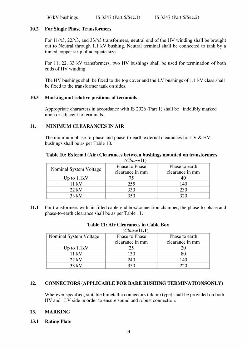
11. MINIMUM CLEARANCES IN AIR
The minimum phase-to-phase and phase-to-earth external clearances for LV & HV
bushings shall be as per Table 10.
Table 10: External (Air) Clearances between bushings mounted on transformers
(Clause11)
Nominal System Voltage Phase to Phase
clearance in mm
Phase to earth
clearance in mm
Up to 1.1kV 75 40
11 kV 255 140
22 kV 330 230
33 kV 350 320
11.1 For transformers with air filled cable-end box/connection chamber, the phase-to-phase and
phase-to-earth clearance shall be as per Table 11.
Table 11: Air Clearances in Cable Box
(Clause11.1)
Nominal System Voltage Phase to Phase
clearance in mm
Phase to earth
clearance in mm
Up to 1.1kV 25 20
11 kV 130 80
22 kV 240 140
33 kV 350 220
12. CONNECTORS (APPLICABLE FOR BARE BUSHING TERMINATIONSONLY)
Wherever specified, suitable bimetallic connectors (clamp type) shall be provided on both
HV and LV side in order to ensure sound and robust connection.
13. MARKING
13.1 Rating Plate

15
Each transformer shall be provided with rating plate made of Anodized Aluminium /
Stainless Steel material securely fixed on the outer body, easily accessible, showing the
information given in Fig. 1 for 3 phase transformers and Fig. 2 for single phase
transformers. The entries on the rating plate shall be indelibly marked for example, by
etching, engraving or stamping.
Fig. 1 Rating plate for 3 phase transformers

16
Fig.2 Rating plate for Single Phase Transformers
13.2 Terminal Marking Plate
Each transformer shall be provided with a terminal marking plate in accordance with Fig.
3 to 5 whichever is applicable.
All dimensions in mm
Fig. 3 Terminal Marking Plate for 3 Phase Transformers without Taps

17
All dimensions in mm
Fig. 4 Terminal Marking Plate for 3 Phase Transformers with Taps
.
Fig. 5 Terminal Marking Plate for Single Phase Transformers
13.3 The rating and terminal marking plates may be combined into one plate at the option of
the manufacturer.

18
13.4 The Distribution Transformer may also be marked with the Standard Mark.
13.4.1 The use of the Standard Mark is governed by the provisions of the Bureau of Indian
Standards Act, 1986 and the Rules and Regulations made thereunder. The details of conditions
under which the licence for the use of the Standard Mark may be granted to manufacturers or
producers may be obtained from the Bureau of Indian Standards.
14 MOUNTING ARRANGEMENT
14.1 The under-base of all three phase transformers upto 200kVA ratings shall be provided
with two 75 x 40 mm channels 460 mm long as shown in Fig. 6 to make them suitable for
fixing to a platform or plinth.
Fig. 6: Mounting Dimension of Transformers up to 200 kVA
14.2 The under-base of all transformers beyond 200 kVA shall be as per Fig. 7 to make them
suitable for mounting on rollers.
Fig. 7 Mounting Dimensions of Transformers beyond 200kVA
NOTE - Bidirectional rollers can also be used as per mutual agreement between User and Supplier.
14.3 Suitable Pole mounting arrangement may be alternatively provided for 3 phase
transformers upto 500 kVA, subject to agreement between User and Supplier.
All dimensions in mm
All dimensions in mm

19
14.4 Single phase transformers are pole mounted type and shall be provided with two mounting
lugs suitable for fixing the transformer to a single pole by means of two bolts of 20 mm
diameter.
Both mounting lugs are made with steel of minimum 5 mm thickness.
14.5 For pad mounted transformers other constructional features and fixing details shall be
subject to agreement between user and supplier.
15 TRANSFORMER TANK
15.1 Construction
15.1.1 For non-sealed or sealed type transformer, Transformer tank can be of plain tank
configuration with/without radiator fins or cooling tubes. The tank can also be made of
corrugated panels of adequate thickness, also used for cooling. The transformer tank
covers shall be bolted/clamped alternatively welded with tank rim so as to make a leak
proof joint. The curb design in case of welded construction shall be such that it is possible
to remove the weld and reweld the tank at least two times.
15.1.2 The transformer tank shall be of adequate mechanical strength to withstand positive and
negative pressures built up inside the tank while the transformer is in operation.
15.1.3 All welding operations shall be carried out by qualified welders.
15.1.4 The tank design shall be such that the core and windings can be lifted freely.
15.1.5 For single phase sealed type transformers, the circular base plate edges of the tank shall
be folded upward for at least 25 mm, to have sufficient overlap with vertical sidewall of
the transformer.
15.2 Pressure and Vacuum Requirements
15.2.1 In case of transformers up to 200 kVA, plain tank shall be capable of withstanding a
pressure of 80 kPa and a vacuum of 250 mm of mercury. Limiting values of the
deflections are specified in Cl. 21.5.1.
For transformers above 200 kVA plain tank shall be capable of withstanding a pressure of
80 kPa and a vacuum of 500 mm of mercury. Limiting values of the deflections are
specified in Cl. 21.5.2.
For single phase transformers up to 25 kVA, the transformer tank shall be of robust
construction round in shape and shall be capable of withstanding a pressure of 100kPa
and a vacuum of 760 mm of mercury.
15.2.2 For three phase transformers up to 2500 kVA, transformer tanks with corrugations shall
be designed for a pressure of 15 kPa measured at the top of the tank with no leakage.
15.2.3 For three phase sealed type transformers with cover welded to the curb of the tank shall
be of sound and robust construction so as to withstand pressure of 80 kPa without any
deformation.
15.2.4 For single phase transformers of sealed type construction, when the space on the top oil is
filled with inert gas, the inert gas plus oil volume inside the tank shall be such that even

20
under extreme operating conditions, the pressure generated inside the tank does not
exceed 0.4 kg/cm2
positive or negative.
15.3 All bolts/nuts/washers exposed to atmosphere shall be as follows.
a) Size 12 mm or below – stainless steel.
b) Above 12 mm – steel with suitable finish like electro 20alvanized with passivation or
hot dip galvanized.
15.4 Gaskets wherever used shall conform to Type III as per IS 11149 / Type C as per IS
4253 (Part 2).
15.5 Inside of tank shall be painted with varnish or oil resistant paint. For external surfaces one coat of thermo setting powder paint or one coat of epoxy primer followed by two coats
of polyurethane base paint shall be used. Table 12 shall be referred to for paint thickness
for normal to medium corrosive atmosphere. For highly polluted atmosphere and special
application external paint work shall be subject to agreement between the user and the
transformer manufacturer.
Table 12 Paint scheme for Distribution Transformers (Clause15.5)
Note: It is recommended to choose paint shade of the transformer as green 218
following IS 5.
16 CONSERVATOR FOR NON SEALED TYPE TRANSFORMERS
16.1 Transformers of ratings 63 kVA and above with plain tank construction, the provision of
conservator is mandatory .For corrugated tank and sealed type transformers with or
without N2 cushion, conservator is not required.
16.2 When a conservator is provided, oil gauge and the plain or dehydrating breathing device
shall be fixed to the conservator which shall also be provided with a drain plug and a
filling hole (1¼” normal size thread) with cover. The capacity of a conservator tank shall
be designed keeping in view the total quantity of oil and its contraction and expansion due
to temperature variations. In addition, the cover of main tank shall be provided with an
air release plug to enable air trapped within to be released, unless the conservator is so
located as to eliminate the possibility of air being trapped within the main tank.
16.3 The inside diameter of the pipe connecting the conservator to the main tank should be 25
to 50 mm and it should be projected into the conservator so that its end is at least 20 mm
above the bottom of the conservator so as to create a sump for collection of impurities.
The minimum oil level corresponding to -5°C should be above the sump level.
S.No Paint Type Area to be
Painted
No. of
coats
Total dry film
thickness
(min.) (microns)
1. Thermo setting powder paint Inside
Outside
01
01
30
60
2. Liquid Paint
22) Epoxy (primer)
b) Polyurethane (Finish coat)
c) Hot oil resistant paint / Varnish
outside
outside
inside
01
02
01
30
25 each
35 / 10

21
17 ABILITY OF TRANSFORMERS TO WITHSTAND EXTERNAL SHORT CIRCUIT
The performance of transformer under external short-circuit conditions shall be in
accordance with IS 2026 (Part 5).
18 EFFICIENCY AND REGULATION
When statements of efficiency and regulations are required they shall be based on
specified loading at the rated kVA and unity power factor and computed in accordance
with Annex B and C respectively.
NOTE Efficiency and regulations at other power factors as agreed between the user and supplier shall also be computed.
19 TOLERANCES
The tolerance on electrical performance excluding losses shall be as given in IS 2026
(Part 1).
20 FITTINGS
20.1 Standard Fittings
The following standard fittings shall be provided:
a) Two earthing terminals with the earthing symbol ╧; b) Oil level gauge indicating oil level at minimum, 30°C and maximum operating
Temperature; NOTES
1) Minimum and maximum positions correspond to the operating temperature of -5°C and 90°C respectively (for Non-
sealed type Transformer).
2) Minimum position corresponds to the operating temperature of 30°C (for sealed type transformers)
c) Air release device (for Non-sealed type Transformers)
d) Rating and terminal marking plates;
e) Above 200 kVA transformers Dehydrating breather shall be provided for
transformers filled with synthetic ester. For transformers filled with Natural esters,
an air cell should be provided in the conservator.
f) Drain cum sampling valve (¾” nominal size thread, IS 554 )preferably steel with
plug for three phase transformers;
g) Thermometer pocket with cap
h) Oil filling holes having (1 ¼ ‘’ nominal size thread) with cover (for sealed type
transformers without conservator).
j) An extended pipe connection on upper end with welded cover for sealed type
transformers. The pipe should be suitably threaded over a sufficient length to
enable use of a refilling/siphon connection after removing the welded cover or any
other similar arrangement capable of reuse. NOTE – The bottom drain valve and filling hole may also be used for filtration purpose.
k) Lifting lugs for the complete transformer as well as for core and winding
assembly.
l) Nitrogen/air filling device/pipe with welded cover capable of reuse (for sealed type
transformer).
m) Pressure relief device or explosion vent above 200 kVA.
n) One filter valve on the upper side of the tank (for transformers above 200 kVA).
o) Unidirectional flat rollers (for transformers above 200 kVA).
p) Inspection hole (for transformers above 200 kVA).

22
q) Pressure gauge for sealed transformers with radiators and nitrogen cushion (above
200 kVA)
r) HV side neutral grounding strip (where one of the HV bushing terminal is
connected to earth).
s) LV earthing arrangement for single phase transformers.
t) Buchholz relay for transformers above 1000 kVA
20.2 Optional Fittings
The following shall be available as additional fittings at the option of the user wherever
specified:
a) Dehydrating breather in lieu of plain breathing device for transformers up to 200
kVA.
b) Filter valve (1¼” nominal size thread, ) for transformers up to 200 kVA.
c) Arcing horns or suitable rating lightning arrestors for HT side – 3 Nos for
transformers up to 200 kVA.
f) Bird Guard
g) Terminal connectors
h) Oil temperature indicator and winding temperature indicators for transformers
above 200 kVA.
j) Jacking pads (for transformer above 1600 kVA)
k) Buchholz relay (for transformers above 200 kVA)
l) Magnetic oil level gauge (for transformer above 1600 kVA) with low oil level
alarm contact.
m) Non return valve (for conducting pressure test).
n) Pressure relief device or explosion vent (up to 200 kVA).
o) Protection relay for sealed type transformers for internal parameters i.e. pressure,
temperature, oil level and gas detection (above 1000 kVA)
p) 4 No’s Anti-Theft stainless steel Fasteners with breakaway nut shall be provided at
top cover (up to 200 kVA)
NOTE IS 3639 describes some of the fittings and accessories
21. TESTS
21.1 General All routine, type and special tests as described in Cl 21.2 to 21.4 shall be
performed as per relevant parts of IS 2026. Pressure and oil leakage test shall be
conducted as per Cl 21.5.
21.2 Routine Tests (to be conducted on all units)
The following shall constitute the routine tests:
a) Measurement of winding resistance (IS 2026 Part 1)
b) Measurement of voltage ratio and check of phase displacement (IS 2026 Part 1 )
c) Measurement of short-circuit impedance (principal tapping, when applicable) and
load loss at 50% and 100% load (IS 2026 Part 1 )
d) Measurement of no-load loss and current (IS 2026 Part 1 )

23
e) Measurement of insulation resistance (IS 2026 Part 1 )
f) Induced over-voltage withstand test (IS 2026 Part 3 )
g) Separate-source voltage withstand test (IS 2026 Part 3)
h) Pressure test (see 21.5)
i) Oil leakage test (see 21.5)
21.3 Type Tests (to be conducted on one unit)
The following shall constitute the type tests:
a) Lightning impulse test (IS 2026: Part 3)
b) Temperature-rise test (IS 2026: Part 2)
NOTE – Maximum measured total loss (No load at rated excitation + load loss at maximum current tap converted to 75 ºC
reference temperature) at 100 percent loading shall be supplied during temperature rise test.
c) Short-circuit withstand test (IS 2026 :Part 5) (up to 200 kVA)
NOTE – Routine tests before and after short circuit test shall be conducted as per IS 2026 (Part 1)
d) Pressure test (see 21.5)
21.4 Special Tests (to be conducted on one unit)
The following shall constitute the special tests which shall be carried out by mutual
agreement between the User and Supplier.
a) Determination of sound levels (IS 2026: Part 10)
b) Short-circuit withstand test (IS 2026: Part 5) (above 200 kVA)
NOTE – Routine tests before and after short circuit test shall be conducted as per IS 2026 (Part 1)
c) No load current at 112.5% voltage (see 5.9.3)
d) Paint adhesion test
The test is performed as per ASTM D3359 (Standard Test Methods for measuring
adhesion by Tape test).
e) BDV and Moisture content of fluid in the transformer IS 16099 and IEEE
C57.147
NOTE Tests at d) and e) may be carried out on more than one unit subject to agreement between user and supplier
21.5 Pressure and Oil leakage Test
21.5.1 For Transformers up to 200 kVA.

24
21.5.1.1 Pressure test (type test)
For sealed type transformers, the transformer tank shall be subjected to air pressure of 80
kPa for 30 minutes and vacuum of 250 mm of Mercury for 30 minutes.
The permanent deflection of flat plates, after pressure / vacuum has been released, shall
not exceed the values given below.
Length of Plate Deflection
Up to 750 mm
5 mm
751 to 1250 mm 6.5 mm
21.5.1.2 Pressure (routine test)
a) Corrugated tanks
The corrugated transformer tank shall be tested for air pressure of 15 kPa above
atmosphere pressure maintained inside the tank for 10 minutes. There should be no
leakage at any point.
b) Sealed type transformers
The transformer with welded cover shall be tested at an air pressure of 80 kPa above
atmosphere pressure maintained inside the tank for 10 minutes.
There should be no leakage at any point.
21.5.1.3 Oil leakage test (routine test)
The assembled transformer with all fittings including bushings in position, shall be
tested at a pressure equivalent to twice the normal head measured at the base of the tank
for 8 Hrs. There should be no leakage at any point. Tank with corrugations shall be
tested for oil leakage test a pressure of 15 kPa measured at the top of the tank for 6
Hrs. There should be no leakage at any point.
21.5.2 For Transformers above 200 kVA and up to including 2500 kVA.
21.5.2.1 Pressure test (Type test)
For non-sealed and sealed type transformers, the transformer tank subjected to air
pressure of 80 kPa for 30 minutes and vacuum of 500 mm of Mercury for 30 minutes.
The permanent deflection of flat plate, after pressure / vacuum has been released, shall
not exceed the values given below.
Length of Plate Deflection
Up to 750 mm
5.0 mm
751 mm to 1250 mm
1251 mm to 1750 mm
Above 1751 mm
6.5 mm
8.0 mm
9.0 mm

25
21.5.2.2Pressure test (routine test)
a)Plain tanks
The transformer tank with welded / bolted cover shall be tested at a pressure of 35 kPa
above atmosphere pressure maintained inside the tank for 10 minutes. There should be
no leakage at any point.
b)Corrugated tanks
The corrugated transformer tank shall be tested for air pressure of 15 kPa above
atmosphere pressure maintained inside the tank for 10 minutes. There should be no
leakage at any point.
21.5.2.3 Oil leakage test (routine test)
The assembled transformer for non-sealed and sealed type with all fittings including
bushing in position shall be tested at a pressure equivalent to twice the normal head
measured at the base of the tank for 8 Hrs. There should be no leakage at any point.
Tank with corrugations shall be tested for oil leakage test a pressure of 15 kPa
measured at the top of the tank for 6 Hrs. There should be no leakage at any point.
21.5.3 For Single Phase Distribution Transformers up to including 25 kVA.
21.5.3.1 Pressure test (type test)
The tank shall be subjected to air pressure of 100 kPa above atmospheric pressure for
30 minutes. There should be no leakage at any point and there is no deformation
of tank.
21.5.3.2 Pressure (routine test)
The transformer tank shall be tested at a pressure of 35 kPa above atmosphere pressure
maintained inside the tank for 10 minutes. There should be no leakage at any point.
21.5.3.3 Oil leakage test (routine test)
The assembled transformer for non-sealed and sealed type with all fittings including
bushings in position, shall be tested at a pressure equivalent to twice the normal head
measured at the base of the tank for 6 Hrs. There should be no leakage at any point.
Tank with corrugations shall be tested for oil leakage test a pressure of 15 kPa
measured at the top of the tank for 6 Hrs. There should be no leakage at any point.
22. INFORMATION REQUIRED WITH ENQUIRY AND ORDER
22.1 The information to be supplied by the manufacturer with enquiry and order to the
purchaser shall be in accordance with Annex D.
ANNEX A
(Clause 2)

26
LIST OF REFERRED INDIAN STANDARDS
IS No. Title
IS 191: 2007 Copper
IS 554 : 1999 Dimensions for pipe threads where pressure tight joints are required on
the threads
IS 1576 : 1992 Solid pressboard for electrical purpose
IS 1608 : 2005 Mechanical testing of metals – Tensile Testing
IS 1747 : 1972 Nitrogen
IS 1885 (Part 38) :
1993
Electrotechnical vocabulary- Part 38: Power Transformers and Reactors
IS 1897 : 2008
Copper strip for electrical purpose
IS 2026 Power transformers
(Part 1) : 2011 General
(Part 2) : 2010 Temperature rise
(Part 3) : 1962 Insulation levels, Dielectric tests and External Clearances in Air
(Part 5) : 2011 Ability to Withstand Short Circuit
(Part 8) : 2009 Application Guide
(Part 10) : 2009 Determination of sound levels
IS 2099 : 1986 Bushings for alternative voltages above 1 000 volts
IS 3024 : 2006 Grain oriented electrical steel sheets and strips
IS 3347 Dimensions for porcelain transformer bushings for use in lightly
Polluted Atmospheres
(Part 1/Sec 1) : 1979 Part 1: Up to and including 1 kV – Section 1 : Porcelain Parts
(Part 1/Sec 2) : 1979 Part 1: Up to and including 1 kV – Section 2 : Metal Parts
(Part 2/Sec 1) : 1979 Part 2: 3.6 kV Bushings – Section 1 : Porcelain Parts
(Part 2/Sec 2) : 1979 Part 2 : 3.6 kV Bushings- Section 2 : Metal Parts
(Part 3/Sec 1) : 1988 Part 3 : 17.5 kV Bushings- Section 1 : Porcelain Parts
(Part 3/Sec 2) : 1988 Part 3 : 17.5 kV Bushings- Section 2 : Metal Parts
(Part 4/Sec 1) : 1988 Part 4 : 24 kV Bushings- Section1 : Porcelain parts
(Part 4/Sec 2) : 1982 Part 4 : 24 kV Bushings- Section 2 : Metal parts

27
(Part 5/Sec 1) : 1979 Part 5 : 36 kV Bushings- Section 1 : Porcelain parts
(Part 5/Sec 2) : 1979 Part 5 : 36 kV Bushings- Section 2 : Metal Parts
IS 3639 : 1966 Fittings and accessories for Power Transformers (under revision)
IS 4253 (Part 2) : 2008 Cork Composition Sheet-Part 2-Cork & Rubber
IS 6162 (Part 1) : 1971 Paper-Covered Aluminum Conductors – Part 1: Round Conductors
IS 6162 (Part 2) : 1971 Paper-covered Aluminum Conductors – Part 2: Rectangular Conductors
IS 7404(Part1) : 1991 Paper Covered Copper Conductors – Part 1 Round Conductors
IS 7421 : 1988 Porcelain bushings for alternating voltages up to and including 1000 V
IS 8999 : 2003 Gauging practice for pipe threads where pressure tight joints are
required on the threads
IS 9335 (Part1) : 1979 Cellulosic papers for electrical purposes: Part 1 Definitions and general
requirements
(Part 2) : 1998 Cellulosic Papers for Electrical Purposes : Part 2 : Methods of test
(Part 3/Sec 1) : 1984 Cellulosic papers for electrical purposes: Part 3 Specifications for
individual materials, Section 1 General purposes electrical paper
( Part 3/ Sec 3) : 1984 Cellulosic papers for electrical purposes: Part 3 Specifications for
individual materials, Section 3 Crepe paper
( Part 3/ Sec 5) :1985 Cellulosic papers for electrical purposes: Part 3 Specifications for
individual materials, Section 5 Special papers
IS 11149 : 1984 Specification for Rubber Gaskets
IS 12444 : 1988 Continuously cast and rolled electrolytic copper wire rods for electrical
Conductors
IS 13730(Part 0/Sec 3)
: 2012
Specification for Particular Types of Winding Wires – Part 0:General
Requirements Sections 1: Enameled Round Copper Wire
( Part 17) : 1996 Particular Types of Winding Wires : Part 17 Polyvinyl acetal enameled
rectangular copper wire, Class 105
(Part 27) : 1996 Specification for Particular Type of Winding Wires – Part 27 : Paper
Covered Rectangular Copper Wire
IS Thermally Upgraded Paper (TUP)
IS 16081 : 2013 Insulating Liquids - Specification for Unused Synthetic Organic Esters
for Electrical Purposes
IS Insulating Liquids – Specification for unused synthetic Natural Esters
for Electrical purposes
IS 13503 Classification of Insulating liquids
IS 16099 Synthetic organic esters for electrical purposes – Guide for maintenance
of transformer

28
ANNEX B
(Clause 18)
METHOD OF DECLARING EFFICIENCY
B-1 EFFICIENCY
B-1.1 The efficiency to be declared is the ratio of the output in kW to the input in kW and calculated
as under.
Total losses comprise:
a) No-load loss, which is considered to be constant at all loads : and
b) Load loss, which varies with load.
The total loss, on load is the sum of (a) and (b).

29
( )
ANNEX C
(Clause 18)
CALCULATION OF INHERENT VOLTAGE REGULATION
C-1INHERENT VOLTAGE REGULATION
C-1.1 The inherent voltage regulation from no-load to a load of any assumed value and power
factor may be computed from the impedance voltage and corresponding load loss measured with
rated current in the winding (see also IS 2026 : Part 8)
Let
I = rated current in winding excited;
E = rated voltage of winding excited;
ISC = current measured in winding excited
EZSC = voltage measured across winding excited (impedance voltage);
PSC = watts measured across winding excited
EXSC = reactance voltage = E2ZSC – PSC
2
ISC
P = Psc corrected to 75oC, and from current Isc to I;
Ex = EXSC x I
ISC
Er = P
I
C-1.2 For rated load at unity power factor, the percentage regulation is approximately equal to
Er% + (Ex%)2
200
Ex% = 100 Ex/E;
Er% = 100 Er/E
n = Ia/I; and
Ia = current in the winding excited during the short circuit tests
corressponding to that obtained when laoding at the assumed load on
the output side and with rated voltage on the input side.
C-1.3 For rated load any power factor cos , the percentage regulation is approximately equal to:
Er% cos + Ex % sin +
(Ex% cos - Er% sin )2
200
C-1.4 For any assumed load other than rated load and unity power factor, the percentage
regulation is approximately equal to;
n.Er% + (n. Ex%)2
200
C-1.5 For any assumed load other than rated load and at any power factor cos , the percentage
regulation is approximately equal to:
n.Er% cos + n. Ex% sin +
(n. Ex% cos - n. Er% sin)2
200
C-1.6 The above formulae are sufficiently accurate for transformers covered by this
specification.
______________

30
ANNEX D
(clause 22.1)
INFORMATION REQUIRED WITH ENQUIRY AND ORDER
A) Normal Information
The following information should be given in all cases:
a) Particulars of the specification to be complied with;
b) Application of Transformer e.g. normal Distribution Transformer, Solar duty, wind
application, Motor starting etc.
c) Single or three phase unit;
d) Number of phases in system;
e) Frequency;
f) Indoor or outdoor type;
g) Type of cooling (KNAN);
h) Rated power (in kVA)
j) Rated voltages (for each winding);
k) State if tappings are required and if on-load or off-circuit tap-changers, or links are
required.
l) Highest voltage for equipment (for each winding);
m) Method of system earthing (for each winding);
n) Insulation level (for each winding), power frequency test level/impulse level;
o) Connection symbol;
p) Neutral terminals, if required (for each winding) and their insulation level to earth;
q) Special requirements of installation, assembly, transport and handling;
r) Fittings required and an indication of the side from which meters, rating plates, oil-level
indicator, etc. may be readable.
s) Natural ester fluid or Synthetic ester fluid
B) Special Information
The following additional information may be required to be given:
a) If a lightning impulse voltage test is required, whether or not the test is to include chopped
waves [see IS 2026 (Part 3)].
b) Impedance voltage at rated current, if specific value is required;
c) Altitude above mean sea-level, if in excess of 1 000 m;
d) Whether transformers will be subjected to frequent overcurrent, for example, furnace
transformers and traction feeding transformers;
e) Any other exceptional service conditions;
f) Whether noise level measurement is to be carried out;
g) Vacuum withstand of the transformer tank, if a specific value is required;
h) Type of Tap-changer controls required (if OLTC is provided);
j) Type of mounting for example pole mounted, ground mounted etc.
k) Any other appropriate information, including reference to any special tests not referred to
above which may be required.

31
ANNEX E
(clause 2.0)
BIBLIOGRAPHY
1. IEC 61039 Edition 2.0 2008, Classification of insulating liquids.
2. IEC 62770 Edition 1.0, 2013, Fluids for electro technical applications – Unused
natural esters and similar electrical equipment
3. IEC 61099 (2010), Insulating liquids – Specifications for unused synthetic organic
esters for electrical purpose
4. IEC 61203 (1992), Synthetic organic esters for electrical purposes – Guide for
maintenance of transformer esters in equipment
5. IEEE Std. C57.147 – 2008, IEEE Guide for acceptance and maintenance of Natural
Ester fluids in Transformers
6. Cigre Brochure 443(Working Group D1.32), DGA in Non-Mineral oil and Load Tap
changers and improved DGA diagnosis criteria
7. Cigre Brochure 436, WG A2.35, October 2010, Experiences in service with new
insulating liquids.
8. IEC 60074-14 (2013), Power Transformers – Part 14: Liquid immersed power
transformers using high-temperature insulation materials.
9. ASTM D 6871-03, Standard specification for natural (vegetable oil) ester fluids in
electrical apparatus
10. ANSI C57.12.22 – 1989, Pad-mounted, Compartmental type self-cooled Three-
phase Distribution Transformers with High-Voltage Bushings, 2500 kVA and
smaller
11. IEEE Std. C57.12.28, IEEE standard for Pad-mounted Equipment – Enclosure
integrity
12. IEEE Std. C57.12.29: 2005, IEEE standard for Pad – Mounted Equipment –
Enclosure integrity for Coastal Environment.
13. IEEE Std. C57.155:2014, IEEE guide for interpretation of gases generated in Natural
Esters and Synthetic Esters immersed transformers.

32
-------------------------